
Abstract
The joint module of collaborative robots must simultaneously guarantee accurate trajectory tracking and strict joint-limit compliance during human–robot interaction. Its nonlinear, strongly coupled and time-varying dynamics, however, amplify the influence of parametric uncertainty, external disturbances, and model errors, causing large tracking deviations. We present a robust, model-based PD controller that explicitly enforces state inequality constraints on joint displacement. A diffeomorphic transformation converts the constrained dynamics into an unconstrained equivalent, allowing standard robust-synthesis tools to be applied while preserving the original limits. Uniform ultimate boundedness of the closed-loop error is proven under lumped uncertainties. Experiments on a 1-DoF joint prototype yield a steady-state tracking error within ±0.1° without violating the prescribed angular bounds, outperforming both unconstrained
1. Introduction
The manufacturing industry is shifting toward human–robot coexistence, where safety and flexibility take precedence over pure operational speed Zhang et al. (2021); Zhu et al. (2023). Collaborative service robots operating in human-populated environments, such as airport VIP lounges (see Figure 1), must therefore achieve accurate trajectory tracking and strict joint-limit compliance simultaneously under significant parametric uncertainties, external disturbances, and unmodeled dynamics. Unlike traditional industrial machines confined to safety cages, these service-oriented robots demand intrinsic compliance and real-time collision detection capabilities Xian et al. (2024); Wang et al. (2022a). Collaborative service robot in an airport VIP lounge.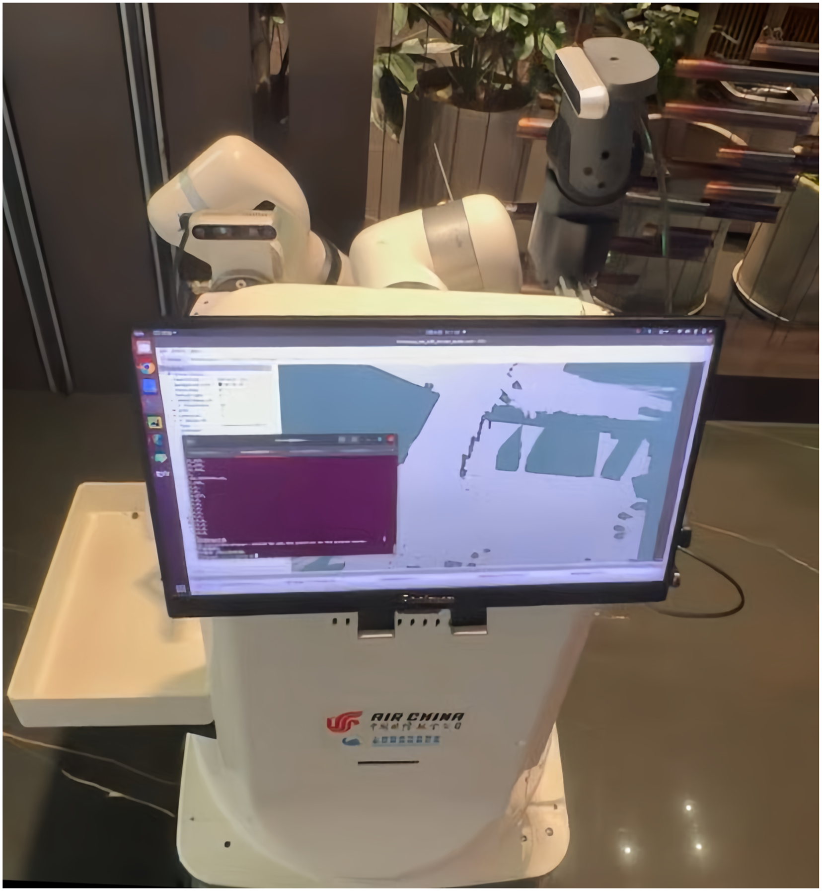
This scenario entails specific joint-level challenges: frequent start-stop operations, varying payloads (e.g., beverage trays of different weights), and the need for smooth motion to ensure guest comfort and safety.
These requirements place stringent demands on the underlying joint modules—integrated electromechanical units comprising servo motors, harmonic reducers, and torque sensors Wang et al. (2024); Chen et al. (2020). As fundamental actuation elements, joint modules serve as the critical interface between high-level motion planning and low-level physical execution.
The performance of robotic joint modules is susceptible to uncertainties including moment of inertia inaccuracies, gear backlash, unmodeled dynamics, and electromagnetic interference Wang et al. (2024). These time-varying, nonlinearly coupled factors complicate precise motion control Ma et al. (2022), necessitating advanced control methodologies that ensure robust tracking performance and disturbance rejection.
Numerous control strategies have been proposed for joint motion control, yet each exhibits distinct limitations. PID control remains widely adopted due to its structural simplicity Shao et al. (2021, 2022), but its fixed linear structure struggles with pronounced nonlinearities in harmonic drive systems, including velocity-dependent friction and position-dependent stiffness. Furthermore, standard PID lacks inherent mechanisms for enforcing physical constraints, typically relying on ad hoc anti-windup techniques that prove inadequate under significant disturbances.
Adaptive control adjusts parameters in response to changing conditions Chen and Hua (2022); Huang et al. (2021); Liu et al. (2021), but requires persistent excitation and substantial computational resources. Neural network controllers provide powerful approximation capabilities Udwadia (2003); Wang et al. (2023a), yet require extensive offline pre-training and lack transparency for safety-critical applications. Fuzzy control offers intuitive rule-based frameworks Zhu et al. (2023), but lacks systematic design procedures and analytical stability guarantees. Model-based robust PD strategies improve tracking through nominal model feedforward Chen (2011), yet primarily focus on asymptotic convergence without explicitly enforcing hard constraints on joint displacement and velocity.
Recent approaches such as sliding mode control and nonlinear model predictive control handle state constraints Zhang et al. (2023a). Sliding mode control confines states within prescribed bounds but inherently induces chattering. Nonlinear model predictive control accounts for constraints through online optimization, but its computational intensity renders it impractical for real-time embedded controllers.
Modern robust control techniques provide a structured framework for managing disturbances, uncertainties, and unmodeled dynamics while maintaining stability guarantees Hale (1969); Sun et al. (2020). These methods offer a promising foundation for achieving precise motion tracking, explicit constraint enforcement, and computational tractability—essential capabilities for safe deployment in demanding service environments.
Safety remains paramount in collaborative robotics. During operation, joint outputs may exceed predefined limits due to unexpected disturbances, leading to potential mechanical damage or human injury. Ensuring that joint angular displacement and velocity remain within strictly defined safe operating ranges constitutes an essential prerequisite for deployment in human-populated environments.
This paper proposes a robust constraint-following control approach based on inequality constraints. The method employs a diffeomorphism transformation to map original state variables into a new coordinate system where they become inherently bounded by construction. This geometric transformation embeds hard constraints into the system dynamics, eliminating the need for explicit constraint checking. Combined with a robust control design compensating for uncertainties characterized by a bounded function ψ, the proposed controller guarantees strict confinement of joint displacement within specified limits. Lyapunov-based analysis demonstrates uniform boundedness and uniform ultimate boundedness Sun et al. (2022).
The main contributions are summarized as follows: (1) A diffeomorphism-based state transformation to convert joint displacement into an inherently bounded variable space. (2) A model-based robust PD control strategy ensuring accurate position tracking under uncertainties while respecting displacement constraints. (3) Comprehensive simulations and hardware-in-the-loop experiments demonstrating steady-state tracking errors within ±0.1° with strict constraint enforcement, outperforming standard robust controllers and PID baselines.
The remainder is organized as follows. Section 2 presents dynamic modeling of the robotic joint module. Section 3 describes the diffeomorphism-based state transformation. Section 4 details the robust controller design and stability analysis. Section 5 presents simulations and experiments. Section 6 concludes with future directions.
2. Dynamic modeling
The joint module of a collaborative robot comprises two primary electromechanical components: a permanent magnet synchronous motor (PMSM) Zhang et al. (2024); Liu et al. (2019) and a harmonic drive reducer Yang et al. (2022a); Qin et al. (2022). The PMSM serves as the primary actuation source, supplying driving torque through precise electromagnetic conversion, while the harmonic reducer introduces notable nonlinearities that significantly complicate transmission characteristics. These nonlinearities include friction torque with strong hysteresis effects—rendering torque transmission direction-dependent and history-dependent—as well as structural compliance originating primarily from flexspline elasticity, which contributes to joint torsional stiffness k. Furthermore, the harmonic drive exhibits kinematic errors due to manufacturing imperfections and assembly misalignments, introducing additional periodic disturbances at the wave generator rotation frequency. These coupled factors, particularly the joint flexibility-induced position error between motor-side and load-side encoders and the hysteresis-related dynamic lag in torque transmission, substantially elevate both modeling complexity and control challenges, necessitating careful consideration of two-inertia resonant dynamics in controller design. The system structure is illustrated in Figure 2. The composition of the joint module system.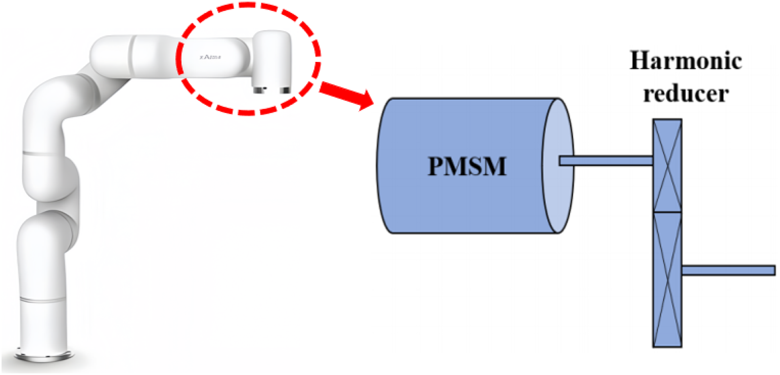
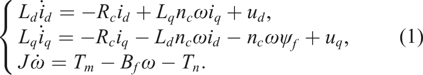
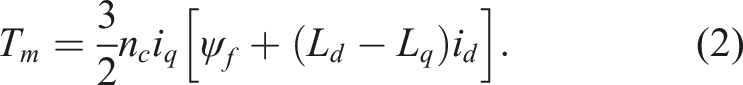
The dynamic characteristics of the PMSM are captured by
Here, i
d
, i
q
, u
d
, u
q
, L
d
, and L
q
denote the stator currents, voltages, and inductances on the d and q axes, respectively; n
c
is the pole-pair count; ω is the rotor angular velocity; ψ
f
is the permanent magnet flux linkage; R
c
is the stator resistance; J is the rotor inertia; B
f
is the viscous-friction coefficient Zhang et al. (2023b); T
m
is the electromagnetic torque; and T
n
is the load torque. The electromagnetic torque is given by
PMSMs are classified into surface-mounted and interior types based on permanent magnet placement. This paper adopts the surface-mounted PMSM (Wang et al., 2022b), where L
d
= L
q
= L. According to the field-oriented control (FOC) principle (Zhao et al., 2022), the d-axis current is regulated to zero (i
d
= 0), yielding i
q
= i
s
(the stator current magnitude). This enables direct torque control through i
q
regulation. Under these conditions, the system dynamics simplify to
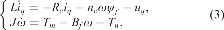
The electromagnetic torque for the surface-mounted PMSM becomes

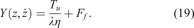
The harmonic reducer transmits torque from the motor to the load. Let T
u
denote the output torque at the reducer, λ the speed reduction ratio, and η the transmission efficiency. The torque relationship is

Let θ
m
denote the motor rotor angular displacement, where

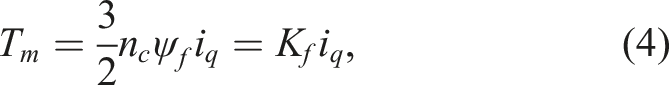
Substituting (6) into (7) to eliminate T
n
gives
Friction significantly influences the stability and tracking accuracy of robotic joints (Hu et al., 2022), particularly in high-precision positioning tasks where stick-slip phenomena degrade performance. Various friction models have been developed, ranging from simple static descriptions to dynamic formulations such as the LuGre and Dahl models that capture hysteresis and rate-dependent behaviors (Wang et al., 2023b). For moderate velocity operation, this paper employs the Coulomb–viscous friction model, which provides a balance between fidelity and implementation simplicity. The friction torque F
f
comprises Coulomb friction (constant at zero velocity) and viscous friction (proportional to velocity):

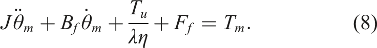
3. State transformation
The joint module dynamics derived in the preceding section are governed by
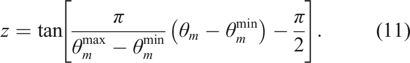
The desired trajectory in the transformed coordinate is
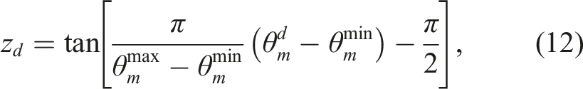
This transformation ensures that
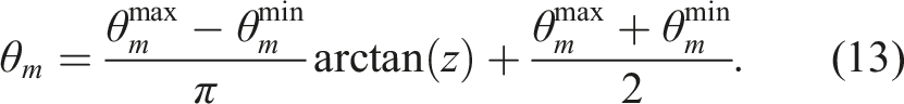
Differentiating (13) with respect to time yields
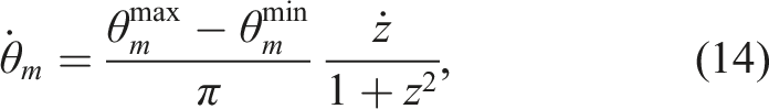
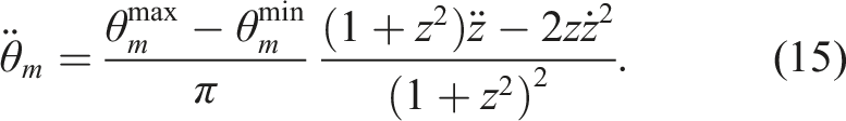
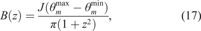
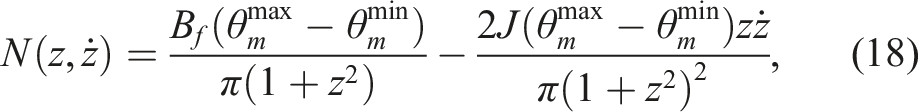
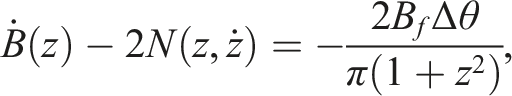
Substituting (14) and (15) into (10) and rearranging terms gives the transformed dynamics:

Here, z ∈ (−∞, + ∞) is the transformed state derived from θ m . The detailed algebraic derivation can be found in our previous work Zhang et al. (2023c). This diffeomorphism maps the constrained physical variable into an unconstrained coordinate while preserving the topological properties of the dynamics, enabling control design without explicit constraint handling.
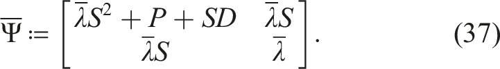
On the compact operating region of interest—where θ is strictly confined within (θmin, θmax) and consequently z remains bounded—the inertia term B(z) in (17) is uniformly positive definite. That is, there exist constants

Extension to multi-joint robots: For multi-joint robots, the proposed method applies naturally to each joint independently. Specifically, for joint i with physical limits
4. Robust control
4.1. Robust controller design
Let the desired trajectory be z
d
(t), with desired velocity

The error derivatives satisfy

Define the error state vector

The control objective is to ensure that
The dynamics (16) can be rewritten in terms of the error dynamics as
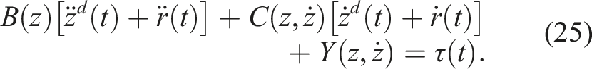
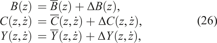
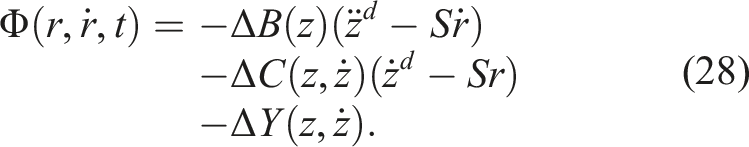
To address system uncertainties, the dynamics are decomposed into nominal and uncertain components:
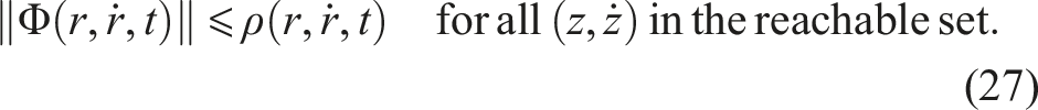
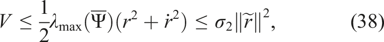
For a given positive constant S, the scalar ρ is chosen as the upper bound of the lumped uncertainty function Φ on the reachable set of the system. Since the diffeomorphic transformation (11) guarantees that z remains bounded for all constraint-satisfying trajectories (as discussed in Assumption 1), the reachable set of
Here
The proposed robust controller is designed as
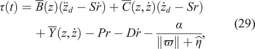


The robust term
The scalars γ and ρ are positive design parameters. The last term in (29) serves as the robust compensation for system uncertainties.
The schematic diagram in Figure 3 illustrates the proposed control structure. Robust control block diagram.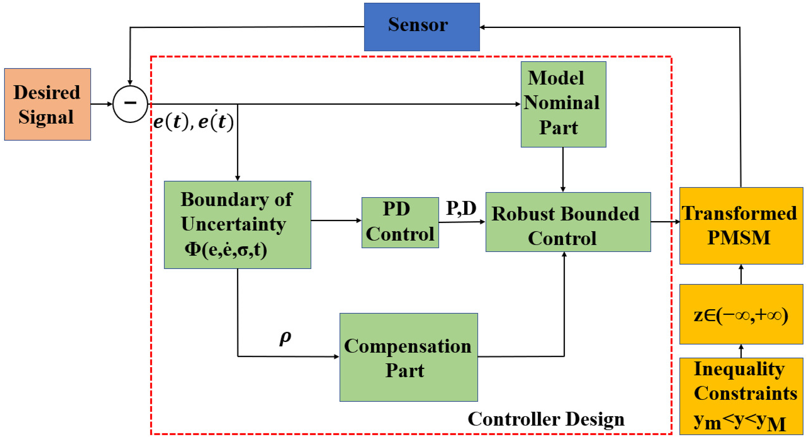
Practical estimation of ρ: In practical implementations, the uncertainty bound ρ is rarely known exactly. The theoretical analysis in Section 4.2 gin Section 4.2 guarantees that uniform boundedness and uniform ultimate boundedness are preserved as long as ρ is chosen conservatively, that is, as an overestimate rather than an underestimate of the true uncertainty magnitude. If the actual uncertainty momentarily exceeds the preset ρ, the Lyapunov derivative
For the joint module considered in this paper, a practical way to estimate ρ is to combine physical reasoning with worst-case experimental observations. The main sources of uncertainty include parameter variations (ΔB, ΔC), unmodeled friction dynamics, and external load disturbances. A straightforward method is to record the tracking error under nominal operation, identify the maximum deviation, and then multiply that value by a safety factor (typically between 1.5 and 2.0) to obtain ρ. Overestimation does not harm stability—it only increases control effort because the robust term becomes more aggressive. This trade-off is discussed in Section 4.3, where we note that larger γ improves precision at the cost of higher energy consumption and potential actuator saturation. Thus, ρ and γ can be tuned jointly to balance robustness against practical constraints such as torque limits and noise sensitivity.
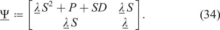
4.2. Theoretical analysis
The stability is analyzed using the Lyapunov method. Select the Lyapunov function candidate
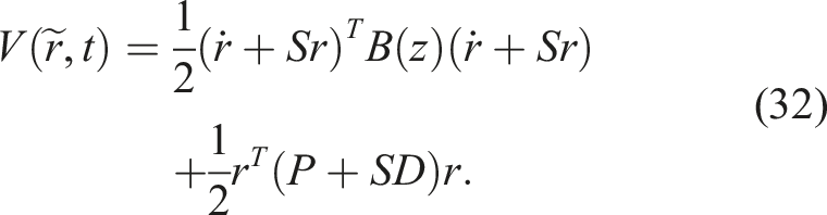
By (20), B(z) is bounded, yielding
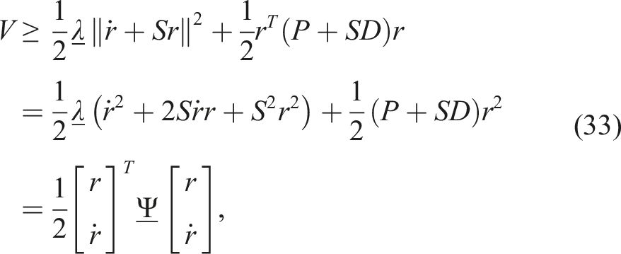
Since
Similarly, by the upper bound of B(z) in (20)
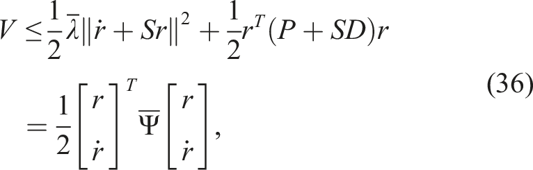
Thus,
Differentiating V with respect to time yields
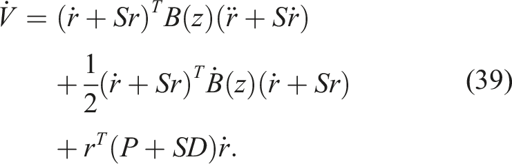
Substituting the error dynamics into the first two terms, denoted as
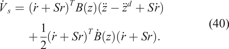
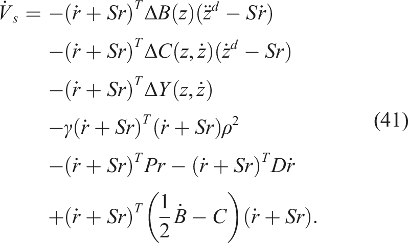
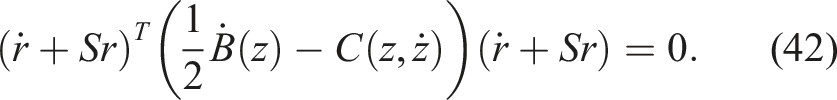
By (21), the skew-symmetry property gives
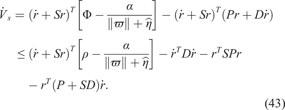
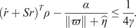
To clarify how the robust term leads to the constant 1/(4γ), we expand the treatment of the inequality involving ρ and α. From the definitions (30) and (31), we have
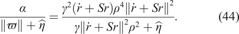
Consider the function
Setting f′(ξ) = 0 yields a maximum at
Then
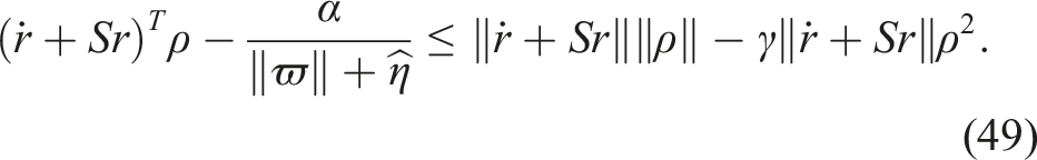
Substituting the bound (50) into (43) and then into (39) yields
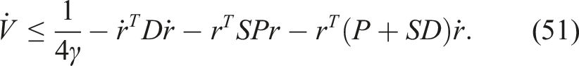
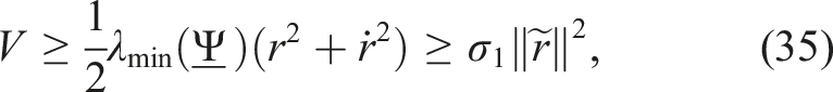
The last three terms can be combined into a quadratic form in

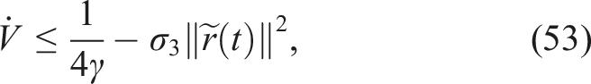
The uniform boundedness is established as follows. For any a > 0 with
This ensures
Furthermore, the uniform ultimate boundedness holds with
4.3. Parameters selection
Control parameter selection determines the trade-off between tracking performance and implementation constraints Li et al. (2022); Ma et al. (2023). Based on the stability analysis, guidelines for tuning the key parameters are as follows.
5. Simulation and experimental
5.1. Numerical simulations
In the following figures, x denotes the joint angular displacement θ and e denotes the tracking error (An et al., 2023). In this section, sinusoidal and step signals were chosen to verify the controller with inequality constraint (MPDW) and without inequality constraint (MPDN) Yu et al. (2024) and PID controller, respectively.

Joint-module parameters.
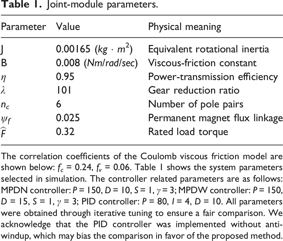
The correlation coefficients of the Coulomb viscous friction model are shown below: f c = 0.24, f v = 0.06. Table 1 shows the system parameters selected in simulation. The controller related parameters are as follows: MPDN controller: P = 150, D = 10, S = 1, γ = 3; MPDW controller: P = 150, D = 15, S = 1, γ = 3; PID controller: P = 80, I = 4, D = 10. All parameters were obtained through iterative tuning to ensure a fair comparison. We acknowledge that the PID controller was implemented without anti-windup, which may bias the comparison in favor of the proposed method.
5.1.1. Step response
For the step signal, set the desired signal amplitude to 135° and set the upper and lower boundaries of the angular displacement to 135.9° and −135.9°, respectively. The simulation results are presented in Figure 4. Under the inequality constraint, the response trajectory more closely follows the reference signal compared with the MPDN and PID controllers, while also exhibiting faster transient response. In addition, the output angle remains strictly bounded within the prescribed upper limit of 135.9° without compromising tracking accuracy. In contrast, both the MPDN and PID controllers exceed this limit during the response process. Simulation results under step signal.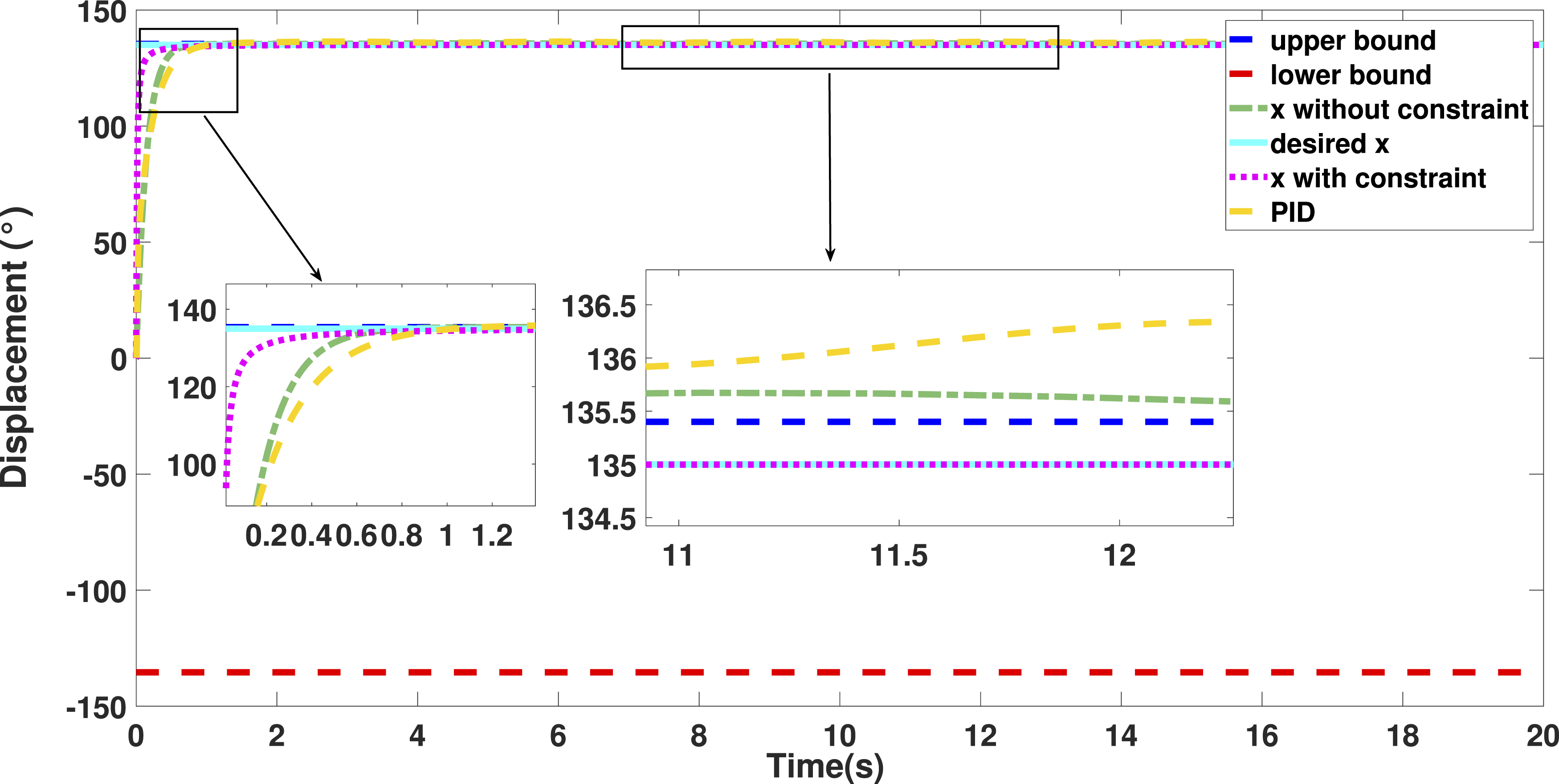
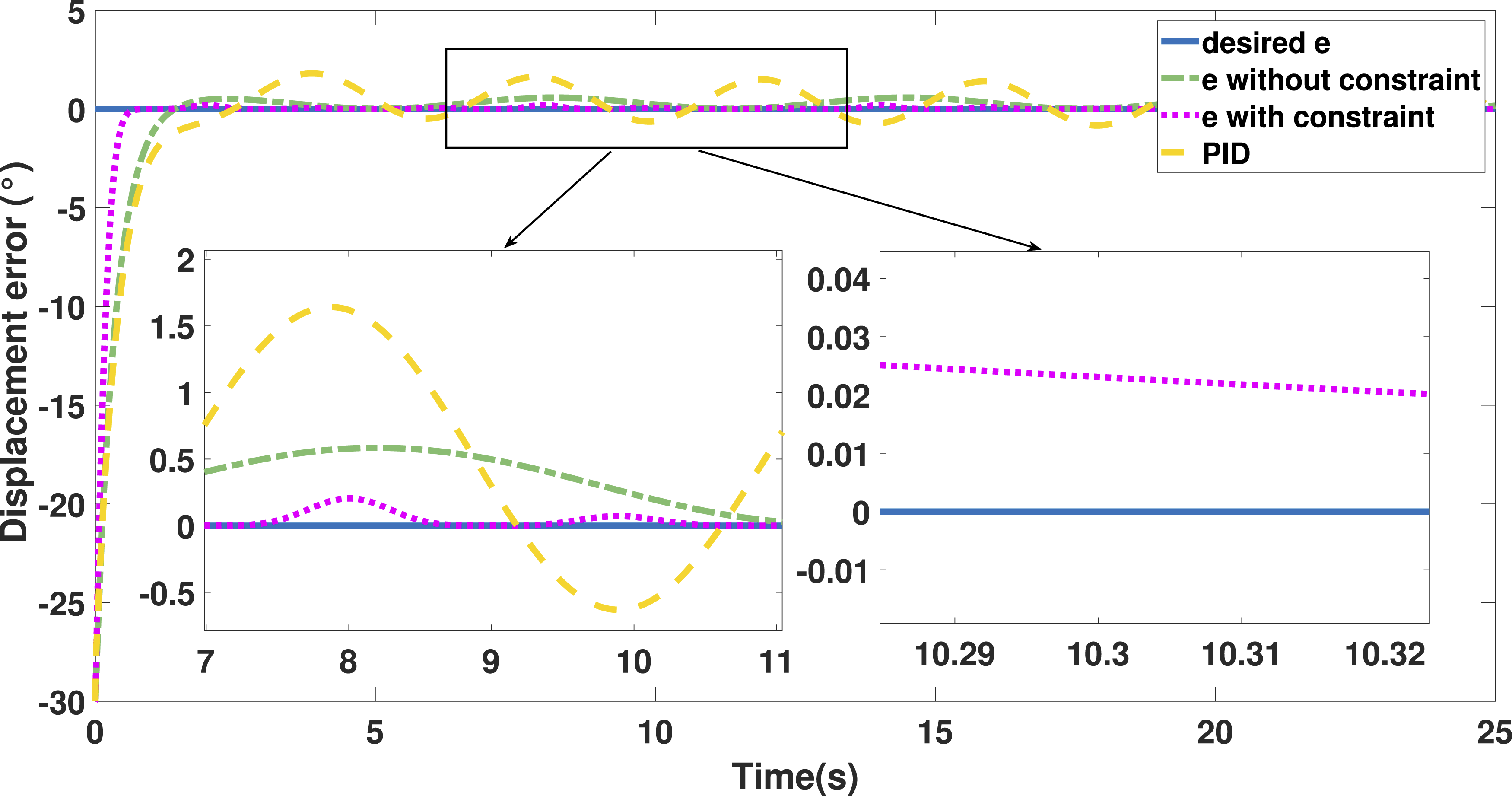
5.1.2. Tracking a sinusoid signal
For the sine signal, the amplitude is 90° and the frequency is 0.2 Hz. Set the upper and lower boundaries of the angular displacement to 91.2° and −91.2°, respectively. The sinusoidal tracking curve and the corresponding steady-state error of the angular displacement of the robotic joint module are illustrated in Figures 5 and 6, respectively. As shown in these figures, the controller with inequality constraints achieves faster dynamic response and more accurate sinusoidal tracking. Moreover, the output trajectory remains strictly confined within the prescribed upper and lower bounds throughout the tracking process, demonstrating effective constraint enforcement capability. When the system is stable, MPDW controller exhibits smaller steady-state error compared to MPDN controller and PID controller. The controller with inequality constraints maintains a steady-state error within 0.03°, whereas the controller without inequality constraints exceeds a steady-state error of 0.5°. The steady-state error for a PID controller exceeds 1.5°. Based on the simulation results, the MPDW controller demonstrates superior dynamic performance. Simulation results under sinusoidal signal. Sinusoidal-tracking error response under simulation conditions.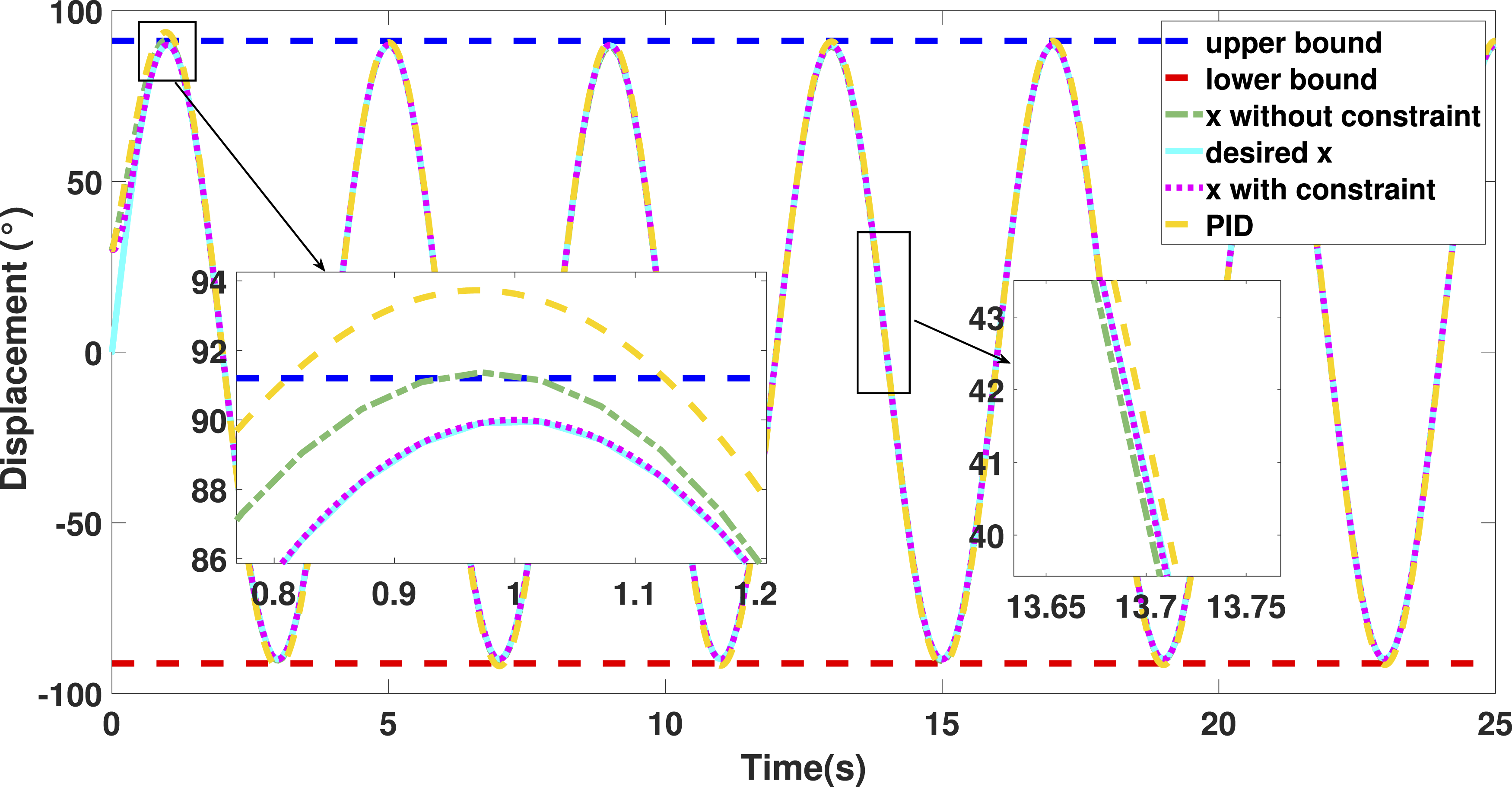
5.2. Experimental platform and experiment results
Figure 7 presents the experimental apparatus employed in this work. The configuration integrates a host computer running MATLAB/Simulink, a joint actuator, the CSPACE real-time control board, a rotary encoder, and a magnetic-particle brake. The implementation of our control algorithm on this experimental platform is mainly divided into the following steps: Collaborative robot joint modular experimental platform.
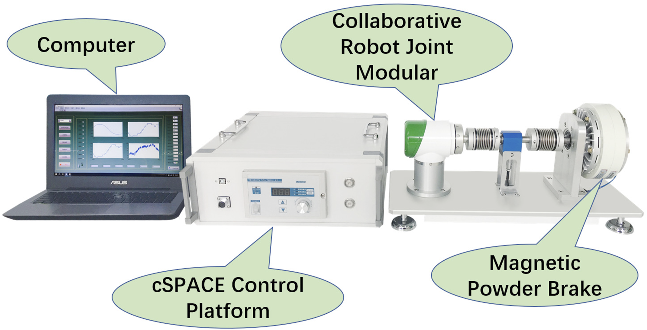
In order to further verify the effectiveness of the proposed control algorithm, sinusoidal and step signals are used as input signals, and the comparison experiment of different algorithms is completed on the robotic joint module platform. In the experimental results, x represents the angular displacement of the robotic joint module and e represents the angular displacement error.
5.2.1. Step response
As in the numerical simulation, set the desired signal amplitude to 135° and set the upper and lower boundaries of the angular displacement to 135.9° and −135.9°, respectively. The experimental results can be seen in Figure 8. Figure 8 demonstrates that the controller with inequality constraints achieves a faster transient response and maintains the output strictly within the prescribed bounds. In contrast, both the MPDN and PID controllers exceed the predefined limits. Moreover, the proposed method exhibits reduced overshoot and improved steady-state convergence characteristics, indicating enhanced constraint-handling capability and robustness. Experimental results under step signal.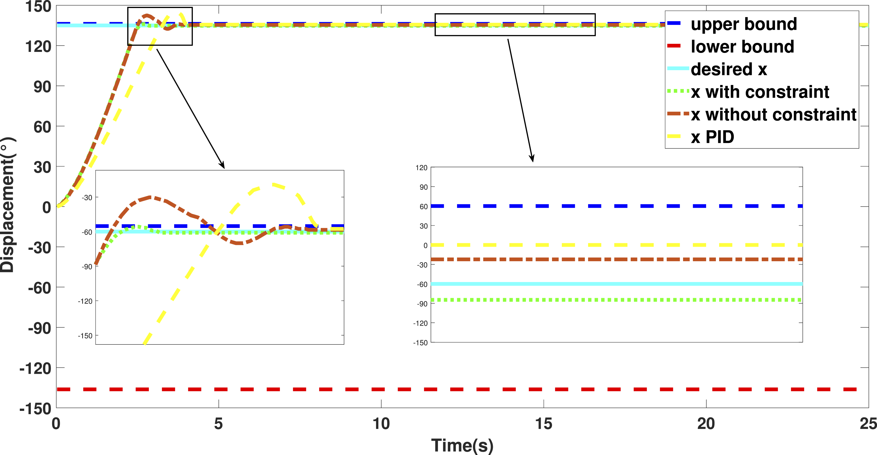
5.2.2. Tracking a sinusoid signal
The same amplitude, frequency and upper and lower bounds are used here as in the numerical simulation. The experimental results are presented in Figures 9 and 10. Figure 9 illustrates the sinusoidal position tracking performance, while Figure 10 depicts the corresponding tracking error curves. As shown in Figure 9, the controller with inequality constraints achieves more accurate sinusoidal tracking and faster dynamic response compared with both the controller without inequality constraints and the PID controller. Moreover, the output trajectory remains strictly confined within the predefined upper and lower bounds throughout the entire motion cycle, demonstrating effective constraint enforcement capability. Figure 10 further indicates that the steady-state tracking error under inequality constraints is stabilized within ±0.08°, whereas the steady-state errors of the controller without inequality constraints and the PID controller are approximately ±0.15° and ±0.2°, respectively. Experimental results under sinusoidal signal. Experimental results of the error tracking under sinusoidal signal.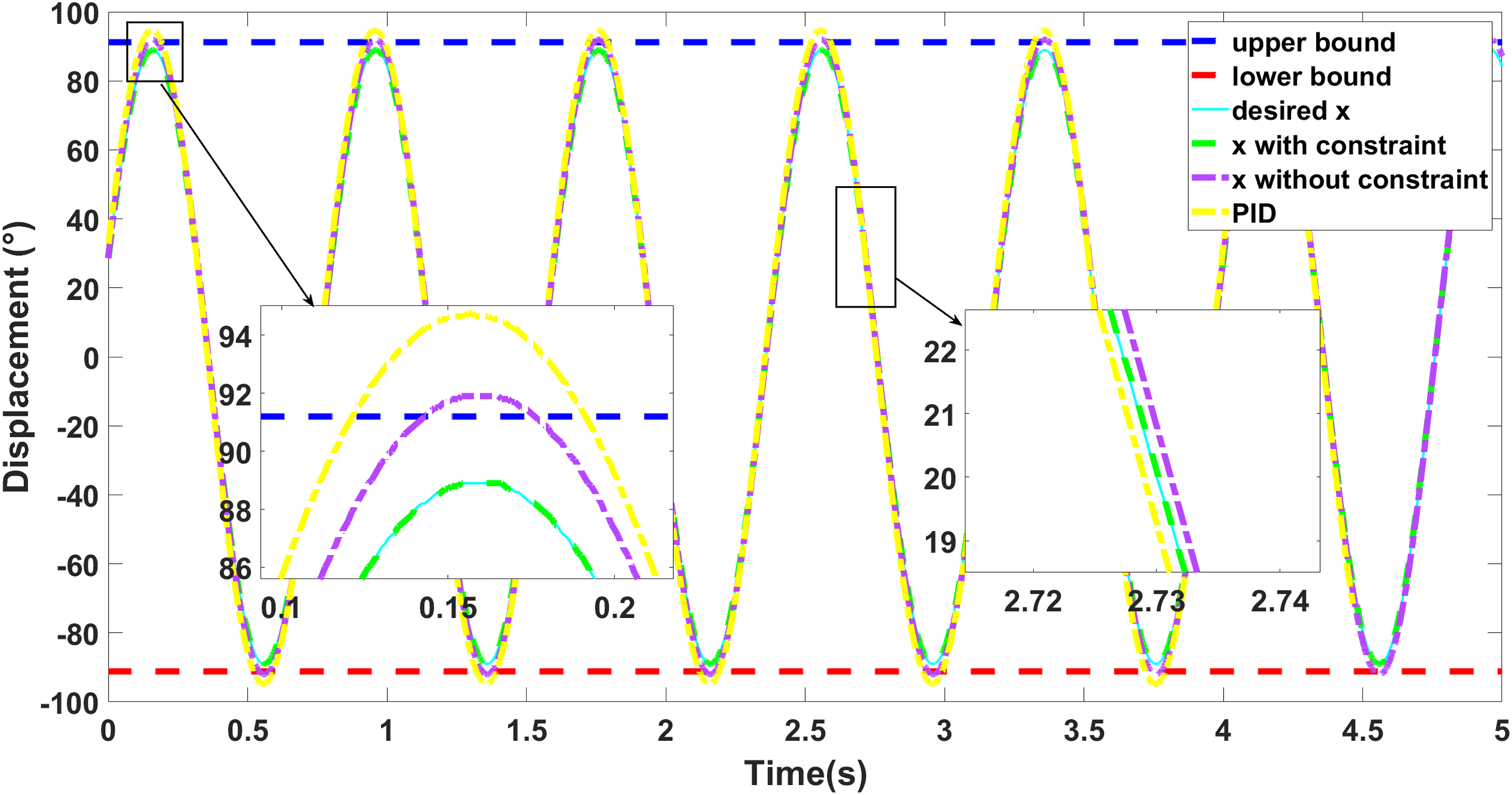
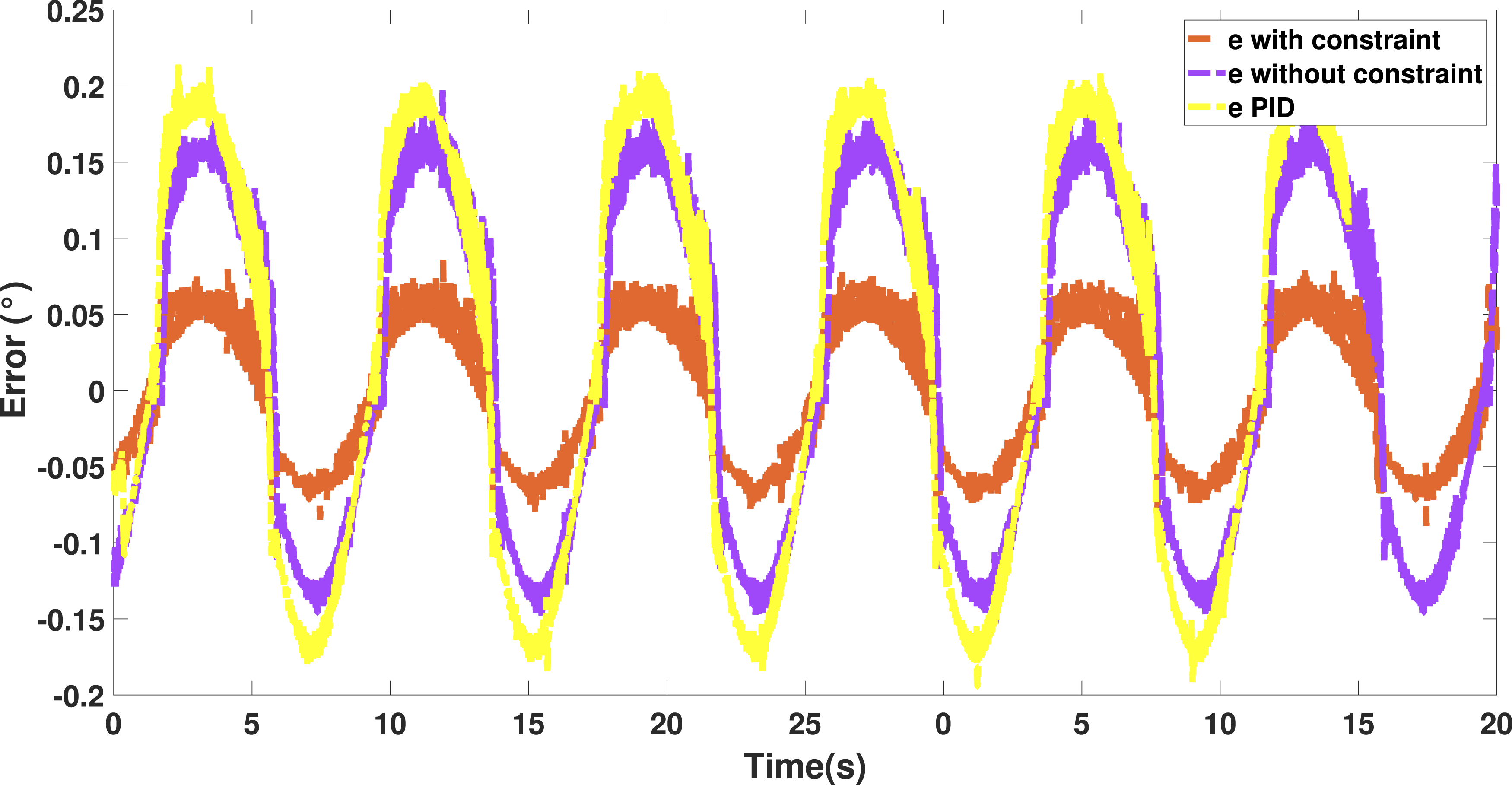
Experiments show that MPDW controller can not only control the angular displacement within the upper and lower bounds, but also reduce the steady-state error and improve the dynamic performance of the system. The experimental results are consistent with the numerical simulations, confirming the validity and practical applicability of the proposed control framework.
6. Conclusions
This work addresses robust control of an uncertain robotic joint module. The scheme integrates a PD core with a robust layer that upper-bounds all parametric uncertainties and external disturbances. By employing the Lyapunov approach, the algorithm’s uniform boundedness and uniform ultimate boundedness are demonstrated. We transform the state of the desired signal to confine the output within the predetermined boundary, as uncertainties in structural deformation, friction, and external load impact the tracking performance of the output angular displacement in the robotic joint module. Finally, experimental evaluations were conducted on a robotic joint module platform, providing a detailed comparison of the results between three distinct algorithms. The results demonstrate that the proposed robust control strategy with inequality constraints not only enhances transient response characteristics but also guarantees bounded steady-state tracking performance under parameter uncertainties and external disturbances. This confirms the effectiveness of integrating inequality-constrained output shaping within a robust control framework. The control algorithm with inequality constraints can effectively limit the output amplitude to a set upper and lower limit without compromising stability and tracking accuracy. Moreover, the robust control algorithm with inequality constraints can address the stability issue of nonlinear multivariable systems of the same type. In future work, we will extend the proposed controller to multi-joint collaborative robots and validate it on an actual service robot in real-world VIP lounge environments under unpredictable human disturbances and varying service loads.
Footnotes
Funding
The authors received no financial support for the research, authorship, and/or publication of this article.
Declaration of conflicting interests
The authors declared no potential conflicts of interest with respect to the research, authorship, and/or publication of this article.