
Abstract
Electronically controlled suspension (ECS) and road noise cancellation (RNC) technologies are widely used in modern vehicles to improve ride comfort and in-cabin acoustic performance. Recent studies indicate that rapidly varying suspension control signals may induce additional high-frequency vibrations and structure-borne noise. However, most ECS studies mainly focus on vehicle dynamics below 20 Hz, while high-frequency vibration behavior remains insufficiently investigated. To address this issue, this study develops a quarter-vehicle model with a rigid-ring tire and a strut-mount bushing to investigate ECS characteristics over the 0–500 Hz range. A frequency-banded evaluation framework is established to analyze both low-frequency suspension performance (0–20 Hz) and high-frequency structure-borne vibration behavior (20–500 Hz). Experimental measurements are conducted to validate the proposed model. Simulation results show that, compared with the conventional quarter-vehicle model, the rigid-ring tire significantly strengthens vibration coupling within the 50–500 Hz band, increasing body vertical acceleration by 174.4%. In contrast, the strut-mount bushing reduces the vibration level by 14.0%. In addition, Linear Quadratic Regulator (LQR) control further amplifies rigid-ring-induced high-frequency vibrations. The influence of control frequency is also investigated, showing that insufficient control frequency may excite structural resonances within the 50–500 Hz range. The proposed model and evaluation framework provide a basis for full-band ECS analysis and improve understanding of the interactions among suspension structure, control strategy, and high-frequency vibration behavior.
Keywords
1. Introduction
Electronically controlled suspension (ECS) systems have become important technologies for improving vehicle ride comfort and driving safety. In parallel, road noise cancellation (RNC) systems have attracted increasing attention because of their ability to suppress structure-borne interior noise below 500 Hz (Yin et al., 2023). As demands for vibration and acoustic comfort continue to increase (Cheer and Elliott, 2015), ECS and RNC are being widely adopted in modern vehicles (P. et al., 2016). Therefore, understanding the frequency-dependent characteristics of ECS-induced structural vibrations is important for future investigations of structure-borne vibration behavior within frequency ranges relevant to RNC systems. However, current studies mainly investigate ECS and RNC independently, and a systematic framework for analyzing ECS-induced high-frequency structural vibrations has not yet been established.
Road surface irregularities are transmitted to the vehicle body through the tire-suspension path, generating both structural vibrations and structure-borne noise. Vibrations below 50 Hz mainly influence ride comfort and tire-road contact, whereas vibrations within 20–500 Hz significantly affect in-cabin acoustic comfort (Guastadisegni et al., 2024). Previous studies showed that suspension nonlinearities can reduce the coherence between wheel vibrations and interior noise, thereby degrading RNC performance (De Brett et al., 2022, 2023). Compared with passive suspension systems, ECS exhibits stronger nonlinearity and time-varying behavior, which may further affect structure-borne vibration transmission. In particular, rapidly varying actuator commands may introduce additional high-frequency structural excitations that propagate through the tire-suspension-body path (Collette and Preumont, 2010). Nevertheless, most existing studies investigate ECS and RNC separately and rarely consider ECS-induced vibrations within the structure-borne noise frequency range (Masri et al., 2024b).
Existing studies indicate that ECS algorithms, including semi-active skyhook control (Collette and Preumont, 2010), active sliding-mode control (H. et al., 2020), and robust control (Guo and Zhang, 2012), may generate rapid control switching and abrupt force variations at high frequencies, thereby introducing additional structural vibrations. When these vibrations couple with tire structural modes (Molisani et al., 2003), they may further influence structure-borne vibration behavior within frequency ranges relevant to RNC systems. To alleviate these high-frequency effects, several approaches have been proposed. Hu et al. (2017) reduced rapid switching in semi-active control by modifying the switching logic of the skyhook strategy. Shen, Li and Huang et al. (2025) improved vibration suppression performance through a fractional-order skyhook-groundhook hybrid control strategy. Shaer et al. (2016) developed a chattering-free fuzzy hybrid sliding-mode controller for electrohydraulic active suspensions, in which low-pass filters with variable gains smooth transitions between the position and force controllers. Similarly, H. et al. (2015) proposed a second-order sliding-mode algorithm that smooths the switching law and eliminates singularities by avoiding fractional-power derivatives in the control input. However, these studies mainly focus on suppressing high-frequency control-induced excitations through algorithmic modifications, while lacking a systematic modeling and frequency-domain analysis framework for investigating the interaction between ECS control actions and suspension structural dynamics within the structure-borne vibration frequency range.
Most ECS studies still rely on simplified linear time-invariant (LTI) suspension models (H. et al., 2023; Theunissen et al., 2021; G. et al., 2024; Shen, Li and Tian et al., 2025; Bajrami et al., 2025), where tire dynamics are represented by equivalent stiffness and the elastic coupling at the strut top is neglected. These models, typically valid below 20 Hz (J. et al., 2020), are effective for controller design but insufficient for capturing high-frequency vibrations within the structure-borne noise frequency range. To overcome these limitations, recent studies have extended quarter-vehicle models by incorporating high-frequency structural dynamics. In tire modeling, the first-order radial structural mode of a tire, usually located around 88–106 Hz (Molisani et al., 2003), dominates its vertical vibration behavior. Below this frequency range, the tire belt behaves approximately as a closed ring, making ring-based tire models widely used in high-frequency dynamic analysis. Min and Wei (2024) proposed a hybrid rigid-flexible ring model to improve tire dynamic modeling accuracy for semi-active suspension control. In this model, the flexible ring was used to calculate tire-road contact forces, while the rigid-ring dynamics were used to determine wheel-center motion. Dwivedi and Wahi (2022) investigated the influence of top-mount bushing flexibility on ride comfort in a quarter-vehicle model and showed that accurate bushing modeling is important for suspension performance analysis. Qing et al. (2011) further developed a rigid-flexible coupled quarter-vehicle model based on Euler–Bernoulli beam theory to improve vibration isolation performance during vehicle transport. These studies demonstrate the importance of incorporating high-frequency structural dynamics into suspension modeling. However, they mainly focus on passive or quasi-passive systems and do not investigate the interaction between ECS control actions and structural vibrations within the structure-borne noise frequency range.
To address these limitations, this study develops a quarter-vehicle model incorporating a rigid-ring tire and a strut-mount bushing to investigate ECS characteristics over the 0–500 Hz range. A frequency-banded evaluation framework is further established to analyze ECS behavior in the ride comfort, vibration-acoustic transition, and structure-borne noise frequency bands. In addition, the influences of ECS control actions and control frequency on high-frequency structural vibrations are systematically investigated. The main contributions are summarized as follows: (1) A dual-effect quarter-vehicle model incorporating rigid-ring tire resonance and top-mount rubber bushing dynamics is developed to investigate ECS behavior over the 0–500 Hz frequency range. The proposed model captures both low-frequency suspension dynamics and high-frequency structure-borne vibration characteristics. (2) A 0–500 Hz frequency-banded evaluation framework is established to systematically analyze ECS behavior across low-frequency, vibration-acoustic transition, and structure-borne noise bands, providing a systematic basis for investigating ECS-induced high-frequency structural vibration behavior. (3) The interaction between suspension structural dynamics and ECS control actions is quantitatively investigated in the mid-to-high-frequency range. Using LQR control as a representative example, the study identifies control-induced structural excitations that cannot be captured by conventional low-frequency models. (4) The influence of control frequency on the overall 0–500 Hz response is analyzed, providing guidance for control update rate selection and actuator bandwidth design to avoid unintended structural excitation.
2. Methodology
An extended quarter-vehicle model is developed by incorporating a rigid-ring tire and a top-mount rubber bushing into the conventional linear time-invariant (LTI) framework, as shown in Figure 1. The conventional low-frequency quarter-vehicle model is used as the baseline (Figure 1(a)). A rigid-ring tire is then introduced to describe the structural dynamics of the tire-wheel assembly (Figure 1(b)), while a top-mount rubber bushing is added to represent the compliance and damping effects in the suspension transmission path (Figure 1(c)). Equivalent quarter-vehicle models: (a) LFM, low-frequency model; (b) HFM-RT, model with a rigid-ring tire; (c) HFM-RB, model with a rigid-ring tire and rubber bushing.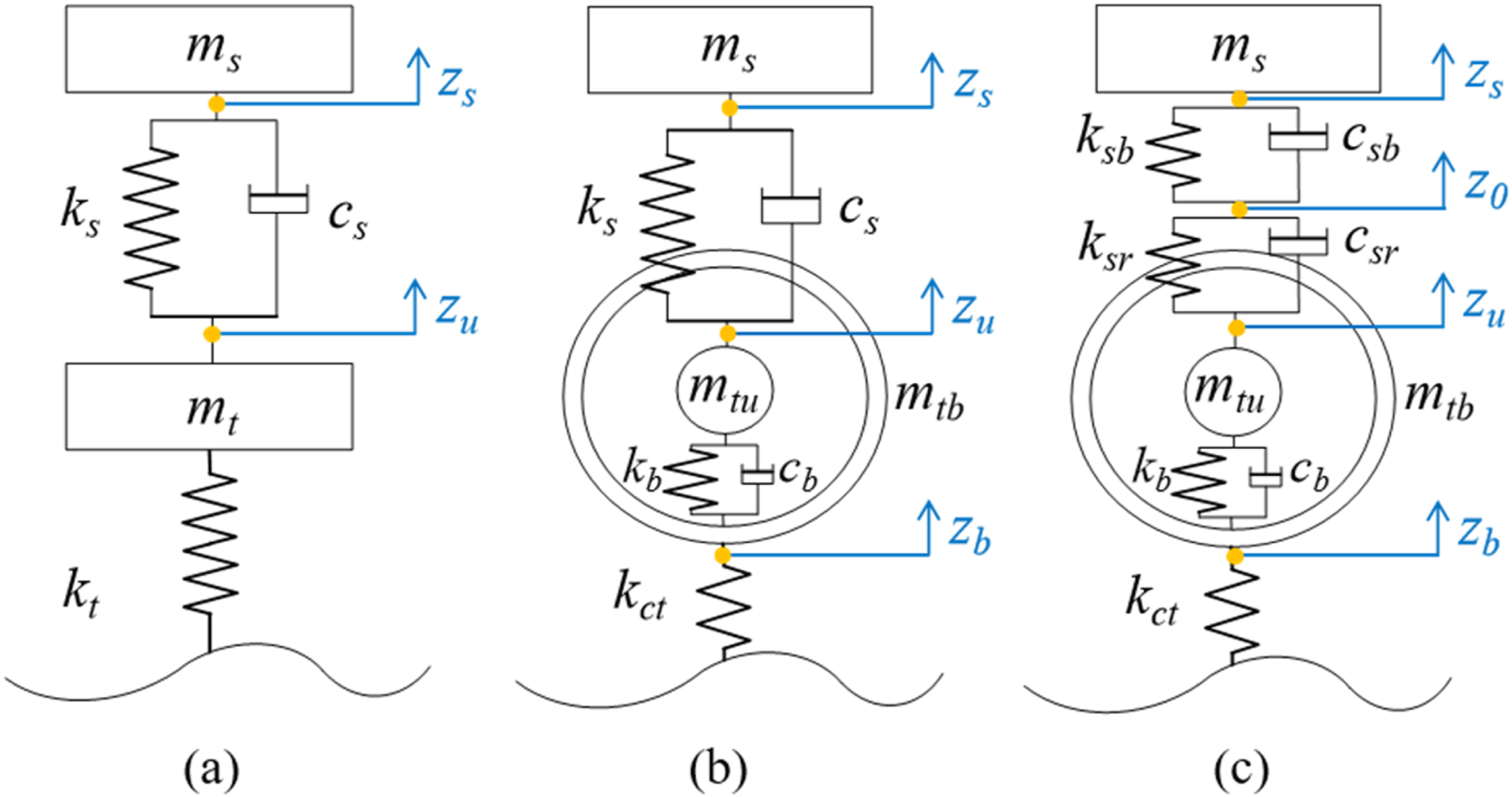
The modeling process is based on the following assumptions: (1) the sprung mass undergoes only vertical motion; (2) continuous tire-road contact is maintained; and (3) the spring and damper behave linearly within their operating ranges.
2.1 Low-frequency LTI quarter-vehicle model (LFM)
The conventional low-frequency quarter-vehicle model consists of a sprung mass, an unsprung mass, a suspension spring-damper system, and tire stiffness, as illustrated in Figure 1(a). The corresponding equations of motion are given in equation (1):
2.2 High-frequency LTI quarter-vehicle model (HFM)
2.2.1 Rigid-ring model
Modal analysis and experimental measurements indicate that the in-plane rigid-body motion of passenger vehicle tires dominates below 100 Hz, where the first radial mode becomes the dominant vibration mode (Zöller et al., 2019). Therefore, the rigid-ring tire model shown in Figure 1(b) is used to capture the dominant tire resonance behavior below 100 Hz. The corresponding equations of motion are given in equation (2):
2.2.2 Rubber bushing model
In the LFM, the suspension is typically assumed to be rigidly connected to the vehicle body. In real vehicles, however, the damper strut is usually connected to the body through a rubber bushing, which introduces additional compliance. As shown in Figure 1(c), the bushing is represented by a Kelvin–Voigt model (KVM) connected in series with the suspension system. Since the bushing mass is much smaller than the sprung mass, only its stiffness and damping effects are considered. The corresponding equation of motion is given in equation (3):
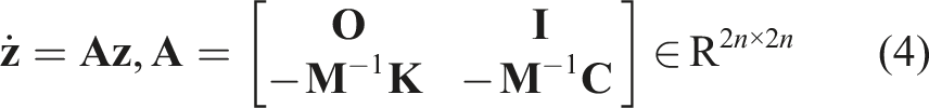
2.3 Complex modal analysis
Complex modal analysis is performed to obtain the natural frequencies and damping ratios of the LFM, HFM-RT, and HFM-RB models. Under free vibration, the governing equations are rewritten in state-space form by introducing the state vector

The model parameters are selected to preserve the low-frequency characteristics of the conventional quarter-vehicle model while introducing representative structural dynamics from the rigid-ring tire and rubber bushing. The extended models are therefore calibrated to match the baseline LTI model below 20 Hz. The LFM parameters follow commonly reported values for C-class passenger vehicles. In the HFM-RT and HFM-RB models, the unsprung mass is divided into a rigid-ring tire mass and a remaining wheel-hub mass. The rigid-ring tire and bushing parameters are adopted from experimentally validated suspension and tire models reported in Qing et al. (2011) The residual suspension stiffness and damping are adjusted to maintain the dominant low-frequency body and unsprung-mass modes across the three model configurations. In addition, the rigid-ring stiffness and contact stiffness satisfy: 1/kb+1/kct = 1/kt. where kt is the equivalent tire vertical stiffness in the LFM.
The parameters used in the following analysis are listed as follows: Sprung mass m s = 300 kg, unsprung mass m t = 36.9 kg, rigid-ring mass m tb = 6.9 kg, and residual mass m ta = 30 kg. Suspension stiffness and damping are k s = 20,000 N/m, c s = 1500 Ns/m; tire stiffness is k t = 244,000 N/m. Rigid-ring stiffness and damping are k b = 1,804,000 N/m, c b = 324 Ns/m, and the contact stiffness is k ct = 282,160 N/m. The bushing is modeled with stiffness k sb = 750,000 N/m and damping c sb = 6000 Ns/m. To maintain equivalent low-frequency dynamics, the residual suspension stiffness and damping are adjusted to k sr = 20,548 N/m and c sr = 2000 Ns/m, respectively.
The mid-to-high-frequency responses are mainly governed by the structural components introduced in the HFM. The rigid-ring parameters, including m tb , k b , and k ct , determine the resonance and vibration transmissibility near the rigid-ring mode at approximately 94.6 Hz. Changes in tire belt mass or sidewall stiffness may shift this resonance and alter the corresponding vibration amplification. The bushing parameters k sb and c sb mainly influence the vibration attenuation characteristics above 50 Hz. A lower bushing stiffness generally improves high-frequency vibration isolation and reduces the vertical body acceleration response in the high-frequency range, whereas higher damping helps suppress resonance peaks in the mid-to-high-frequency range. Therefore, the selected parameters preserve the low-frequency suspension behavior while capturing the relative mid-to-high-frequency vibration trends induced by the added structural components.
Modal characteristics of LFM, HFM-RT, and HFM-RB.
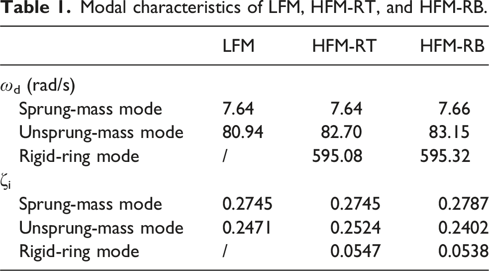
In this table, ωd denotes the damped natural frequency, and ζ i denotes the modal damping ratio of the i-th mode. The comparison shows that the deviations in low-frequency natural frequencies and damping ratios among the three models remain below 3%. This confirms their low-frequency equivalence. Meanwhile, the HFM-RT and HFM-RB models additionally capture the rigid-ring and bushing-related effects in the 20–500 Hz range.
2.4 Transfer function analysis
The transfer function from road input velocity to body acceleration is analyzed in the frequency domain using white-noise road excitation (Collette and Preumont, 2010). The transfer function is expressed in equation (6), and the corresponding Bode plots are shown in Figure 2. Bode plot of the transfer function from 
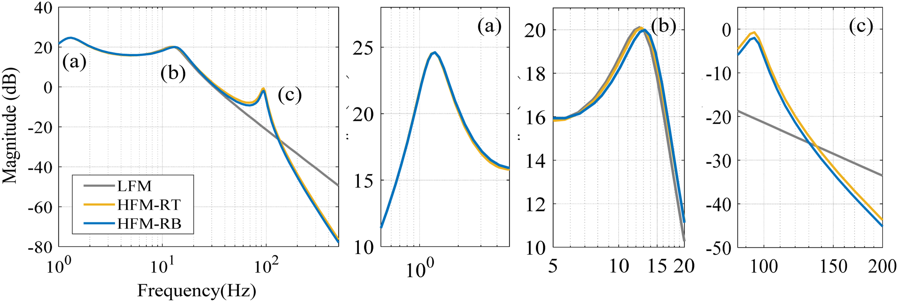
Figure 2 shows that the three models exhibit similar frequency responses near the sprung-mass natural frequency (1.32 Hz), confirming their equivalence in the low-frequency range. Slight differences appear near the unsprung-mass natural frequency (12.7 Hz). Modal analysis further indicates that the deviations in natural frequency and damping ratio remain below 3%, supporting the validity of the proposed models for ECS analysis below 20 Hz. In the mid-to-high-frequency range, the rigid-ring tire model introduces a distinct resonance peak near 94.6 Hz, reflecting the structural dynamics of the tire. In contrast, the rubber bushing significantly reduces vibration transmissibility above 50 Hz because of its isolation effect in the suspension transmission path. These results demonstrate that the proposed model can capture the main vibration characteristics within the 20–500 Hz range.
2.5 Experimental validation
To validate the proposed high-frequency quarter-vehicle model, experimental measurements are conducted. The measured responses are compared with simulation results in the frequency domain, particularly near the dominant resonance regions. Figure 3 shows the test vehicle, road condition, and sensor layout used in the experiments. Road test configuration. (a) Test vehicle and coarse asphalt road surface within the campus; (b) Wheel acceleration sensor layout; (c) Body acceleration sensor layout.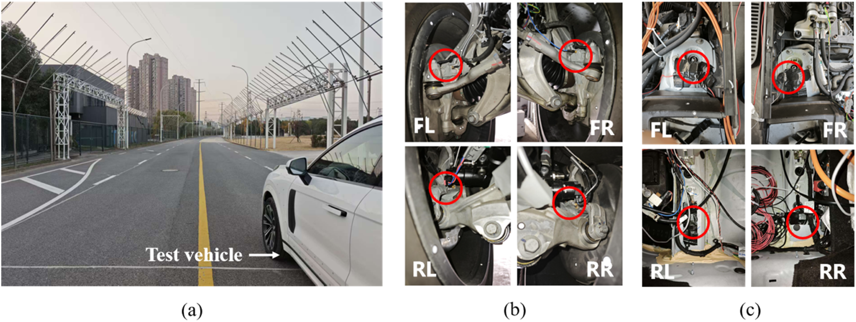
The equivalent quarter-vehicle parameters used in both the experiments and simulations correspond to the front axle configuration, including a sprung mass of 559 kg, an unsprung mass of 72.6 kg, a suspension stiffness of 36 N/mm, and a tire vertical stiffness of 307 N/mm. The corresponding static wheel load is 6.20 kN. Vertical accelerations of the sprung and unsprung masses are measured using single-axis MEMS accelerometers. Different sensor ranges are selected to accommodate the vibration characteristics of the vehicle body and wheel assembly. The sprung-mass acceleration is measured using a ±30 g accelerometer with a resolution of 1.47 mgrms, whereas the unsprung-mass acceleration is measured using a ±200 g accelerometer with a resolution of 9.8 mgrms.
The vehicle is driven on a coarse asphalt road surface at a constant speed of 30 km/h. Acceleration signals are measured near the tire center and above the damper mount on the vehicle body. The measured signals are resampled to 1024 Hz for subsequent analysis. In the simulations, a random road profile with an equivalent roughness level is applied using a sampling frequency of 10 kHz. The simulated signals are also resampled to 1024 Hz for consistency. Figure 4 compares the power spectral density (PSD) of the simulated and measured acceleration responses. Comparison of the power spectral density (PSD) of the acceleration responses between simulation and experiment: (a) Wheel; (b) Body.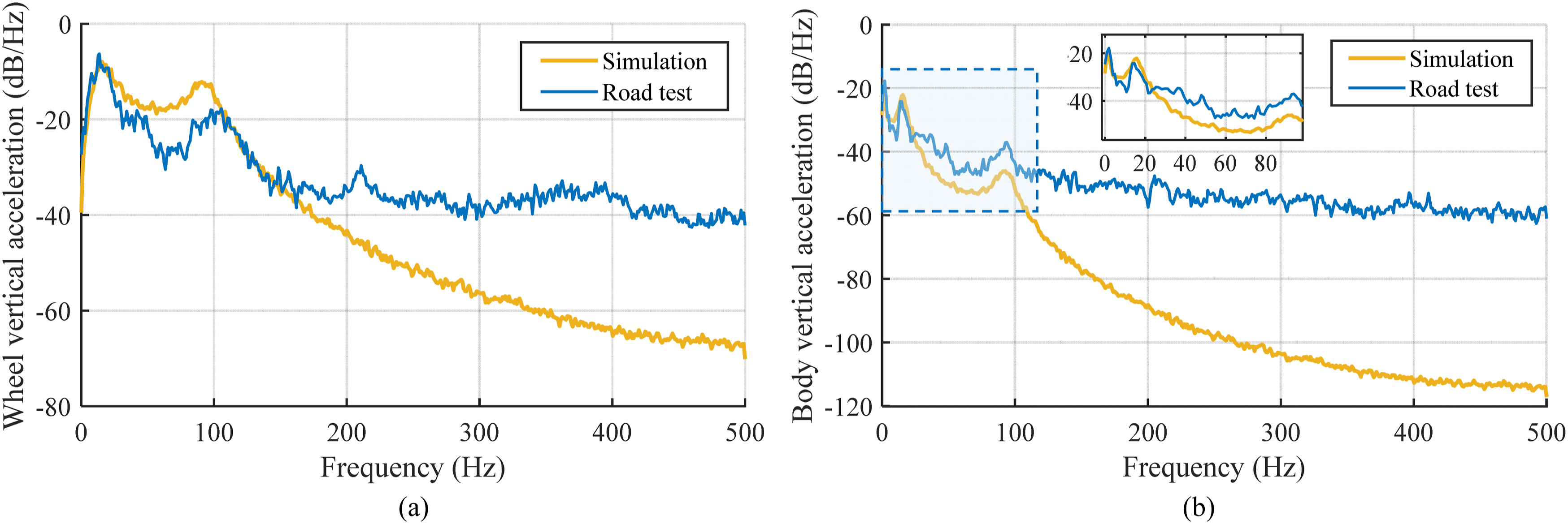
The simulation results agree well with the experimental measurements below 100 Hz and successfully capture the primary rigid-body resonance modes. However, noticeable discrepancies appear above 100 Hz. These discrepancies mainly arise from the simplifying assumptions adopted in the present reduced-order framework. The model considers only vertical linear dynamics and is intended to capture the dominant vibration transmission characteristics of the suspension system. Consequently, several complex mechanisms in practical vehicles are not fully represented, including multi-directional structural coupling, suspension nonlinearities, higher-order tire modes, and structural-acoustic interactions. In addition, vibration responses above 100 Hz are influenced by several unmodeled mechanisms, including tangential-force-induced tire vibration (350–500 Hz), radial-force-induced tire cavity resonance (190–250 Hz), and the intricate global (50–100 Hz) and local (120–350 Hz) structural-acoustic coupling modes of the vehicle body panels and cabin structures. These effects are not fully represented in the present reduced-order model, which may lead to under-representation of certain high-frequency vibration and noise amplification phenomena observed in practical vehicles. Consequently, the predictive accuracy gradually decreases above 100 Hz.
Nevertheless, the model still captures the dominant vibration trends within the investigated frequency range. Based on this bounded validation, the proposed model is subsequently used to investigate the full-band (0–500 Hz) vibration behavior of the ECS across different frequency regions.
3. Control strategy
Figure 5 illustrates the quarter-vehicle models with active suspension control, where F
a
denotes the control force generated by the actuator. Quarter car model with active suspension: (a) LFM; (b) HFM-RT; (c) HFM-RB.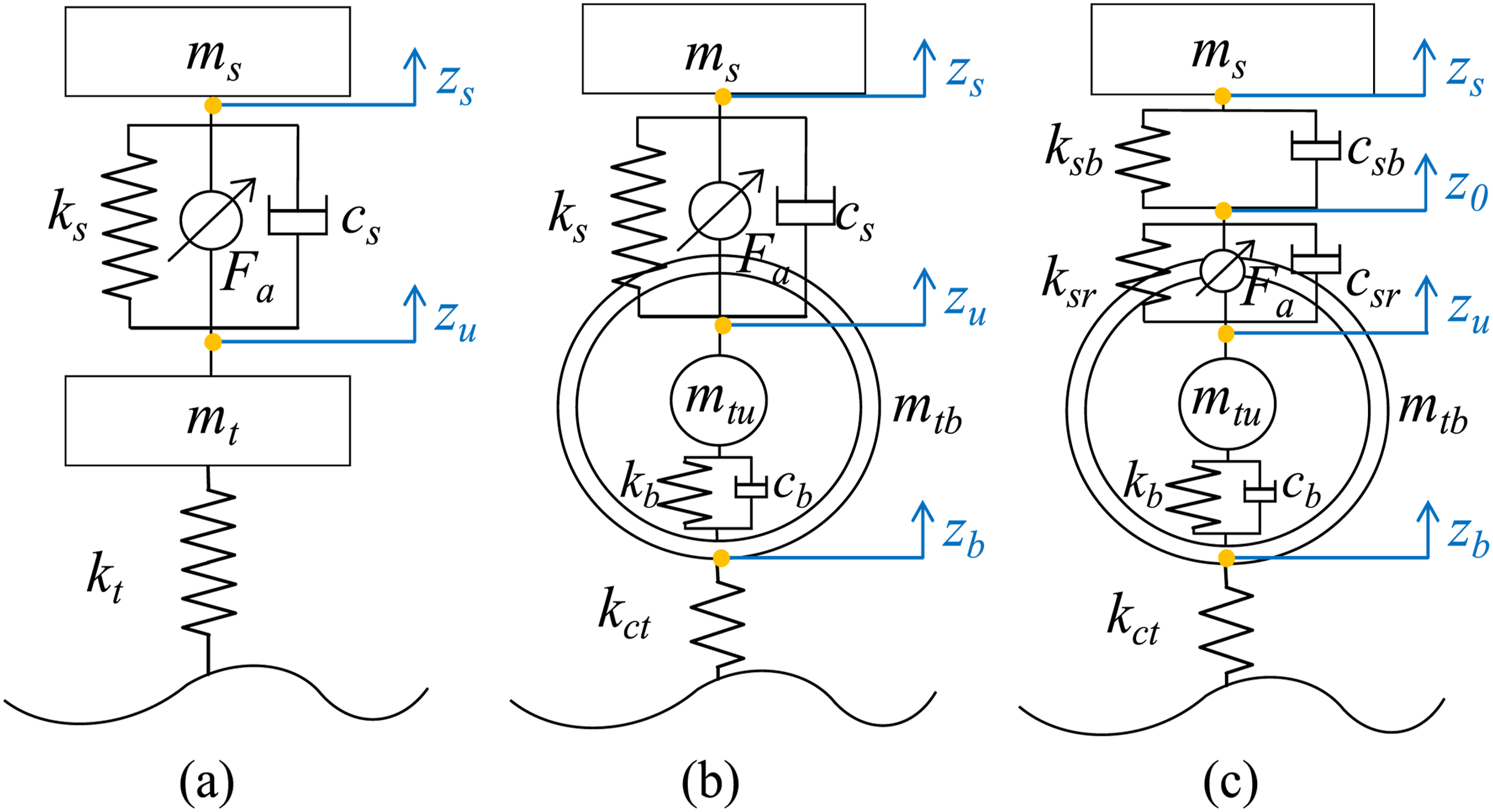
The state-space form of the system is expressed as equation (7):
Taking the LFM as an example, the control objective and state variables are defined as follows (the corresponding definitions for the other models are provided in Appendix A):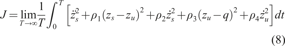

The unified control objective is written as equation (9):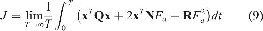

To ensure consistent control objectives among the three models and facilitate comparison of the rigid-ring tire and rubber bushing effects under active control, the same weighting parameters are adopted: ρ1 = 40, ρ2 = 100, ρ3 = 40, and ρ4 = 16 (Butsuen, 1989). A relatively larger value is assigned to ρ2 because the corresponding state
In the HFM-RB model, the suspension deflection is redefined from z s -z u , as used in the LFM and HFM-RT models, to z0-z u , where z0 represents the displacement at the connection point between the bushing and the vehicle body, as illustrated in Figure 5(c). This modification allows the influence of sensor location and bushing compliance on control performance to be further investigated. In addition, it improves consistency between the theoretical model and practical sensor layouts in real vehicles, thereby facilitating experimental validation.
4. Results and discussion
The control system adopts a hierarchical structure in which the outer loop computes the desired suspension force, while the inner loop generates the corresponding actuator commands. As illustrated in Figure 6, the vehicle states are discretely sampled and processed by the controller. The control signals then pass through a delay block and are converted into continuous signals using a zero-order hold (ZOH) before being applied to the actuator. The simulation step size is set to 0.0001 s to capture the continuous vehicle dynamics, while the signals used for analysis are sampled at 1000 Hz. Quarter car active suspension control circuit.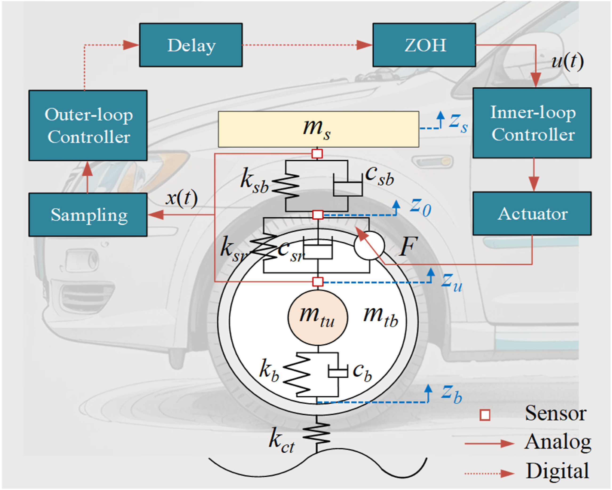
4.1 Evaluation framework
An evaluation framework is established based on the dominant frequency characteristics of the suspension system and structure-borne vibration behavior inside the cabin. The frequency range is divided into three regions. (1) 0–20 Hz: Suspension vibration dominant frequency band
This frequency range is mainly associated with the vehicle’s vertical, pitch, and roll motions and directly affects ride comfort. Ride comfort can be divided into primary (0–5 Hz) and secondary (5–20 Hz) regions (Eichberger and Hofmann, 2007). Primary ride comfort is related to the body bounce, pitch, and roll modes near their natural frequencies, whereas secondary ride comfort is mainly influenced by the unsprung-mass vertical modes (10–16 Hz) and powertrain modes (7–18 Hz).
To evaluate the suspension performance in this frequency range, the following indicators are adopted to assess ride comfort and driving safety: (2) 20–50 Hz: Vibration-acoustic transition frequency band
Above 20 Hz, while human sensitivity to whole-body vertical vibration declines (Standard, 1997), localized vibrations at the seat, steering wheel, and floor remain perceptible. This frequency band mainly reflects the mid-frequency structural dynamics of the suspension system and local body modes, including the unsprung-mass longitudinal mode (20–23 Hz), the first bending mode (∼21 Hz), and the torsional mode (∼25 Hz) (Masri et al., 2024). Strong road excitation may also induce structural resonance and vibration amplification within the 30–50 Hz range (Oh et al., 2018).
The evaluation indicator used in this frequency band is defined as equation (15): (3) 50–500 Hz: In-cabin structure-borne noise dominant frequency band
The 50–500 Hz frequency range characterizes the interior structure-borne noise response, predominantly influenced by tire-road interaction and structural vibration transmission. Key noise sources include tangential-force-induced tire noise (350–500 Hz), radial-force-induced cavity resonance (190–250 Hz), and structure–acoustic coupling of the body panels and cabin, both globally (50–100 Hz) and locally (120–350 Hz). Since structural vibrations can propagate into the cabin through the body structure, the RMS value of body vertical acceleration is adopted to evaluate the corresponding vibration response:
The rigid-ring tire model adopted in this study is physically applicable mainly below 100 Hz. Therefore, although the analysis extends to 500 Hz, the results above 100 Hz should be interpreted mainly as comparative trends rather than precise quantitative predictions.
4.2 Impact of high-frequency suspension components
The LFM, HFM-RT, and HFM-RB models under passive and active control conditions are simulated using an ISO 8608 Class C random road input. The results are analyzed based on the evaluation metrics defined in Section 4.1.
4.2.1 Passive model comparison
Evaluation results of P-LFM, P-HFM-RT, and P-HFM-RB.
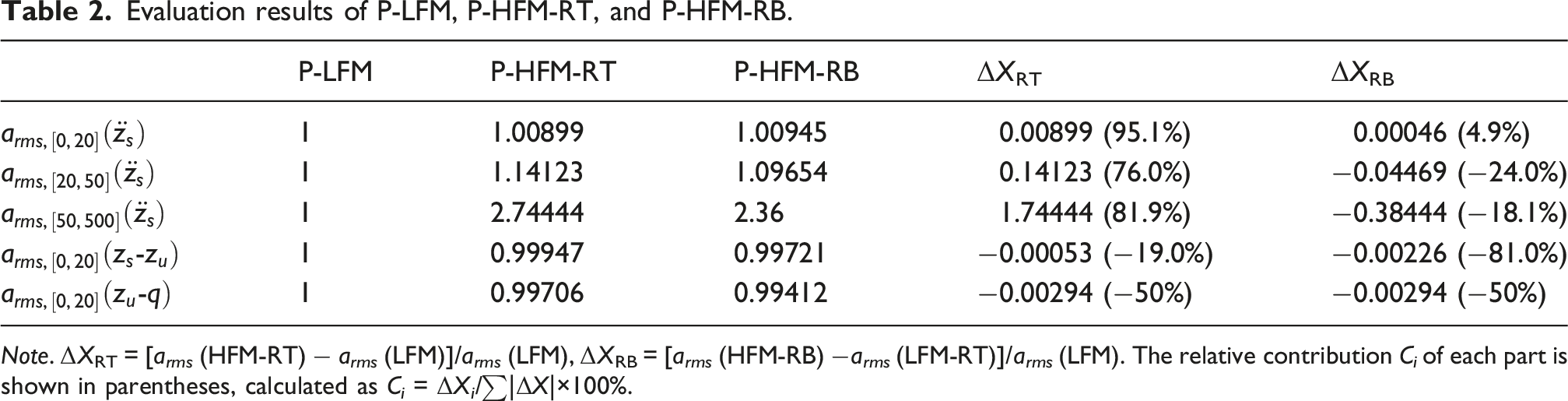
Note. ΔXRT = [a rms (HFM-RT) − a rms (LFM)]/a rms (LFM), ΔXRB = [a rms (HFM-RB) −a rms (LFM-RT)]/a rms (LFM). The relative contribution C i of each part is shown in parentheses, calculated as C i = ΔX i /∑|ΔX|×100%.
The results in Table 2 are further illustrated in the radar chart shown in Figure 7. Evaluation results of P-LFM, P-HFM-RT, and P-HFM-RB.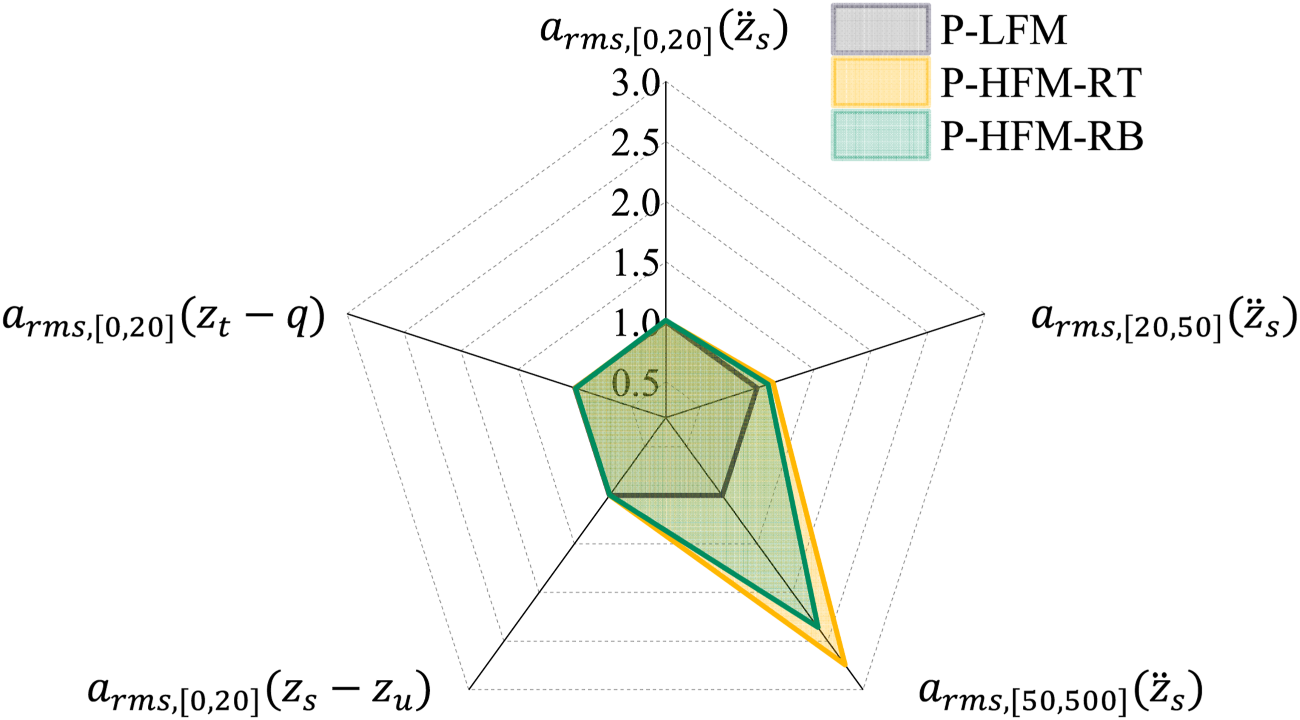
According to Table 2 and Figure 7, the rigid-ring tire and rubber bushing have little influence on suspension behavior within the 0–20 Hz range, where the variations in performance indicators remain below 1%. However, their effects become significantly different in the 20–500 Hz range. The rigid-ring tire increases performance indicators by 14.1% in the 20–50 Hz range and by 174.4% above 50 Hz. This amplification trend is consistent with the frequency response characteristics shown in Figure 2(c), indicating that the rigid-ring mode enhances the transmission of mid-to-high-frequency vibrations. In contrast, the rubber bushing reduces the corresponding indicators by 3.8% within the 20–50 Hz range and by 14.0% above 50 Hz because of its vibration isolation effect. However, it should be emphasized that the “rigid” assumption may no longer fully represent the real tire dynamics above 100 Hz. In this range, flexible belt deformation and circumferential wave propagation become dominant excitation sources, which the current model approximates only qualitatively.
4.2.2 Active model comparison
Active control simulations are conducted using a first-order actuator model to represent practical actuator dynamics. The actuator transfer function is defined as G = 300/(s + 300), corresponding to a response time of approximately 10 ms. Model A-HFM-RB-AD1 represents systems with first-order actuator dynamics. The A-HFM-RB-AD1 model additionally includes the first-order actuator dynamics.
Control gains for different models.
As shown in Table 3, the HFM-RT and HFM-RB models introduce additional rigid-ring and bushing states, resulting in expanded feedback gain vectors compared with the conventional LFM. These gains are obtained through the LQR optimization process and indicate the relative contribution of different vibration states to the control objective.
Evaluation results of LFM, HFM-RT, HFM-RB, and HFM-RB-AD1.
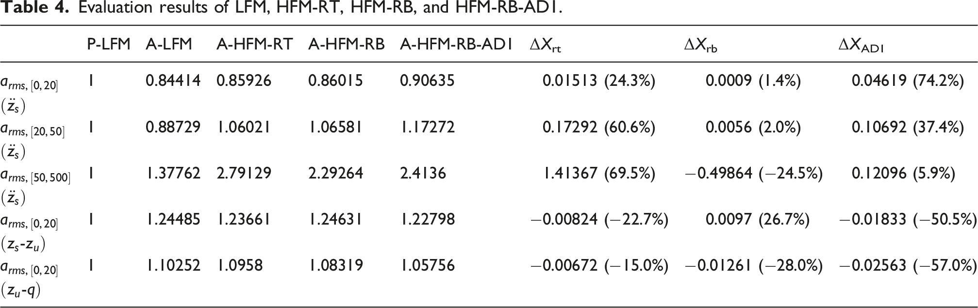
Evaluation results of LFM, HFM-RT, HFM-RB, and HFM-RB-AD1.
It should be clarified that the 0–500 Hz range considered in this study represents the vibration evaluation range rather than the actuator force-tracking bandwidth. The first-order actuator model is introduced to represent the finite dynamic response of practical active suspension actuators instead of accurately tracking force commands over the entire frequency range. The corresponding bandwidth is approximately 47 Hz, with a response time of 10 ms. These values are representative of high-response hydraulic servo actuators (Shen and Peng, 2004) and electromechanical active suspension actuators (Van der Sande et al., 2013) used in advanced chassis control applications. As shown in Table 4, although actuator dynamics introduce noticeable degradation in the low- and mid-frequency control performance, the A-HFM-RB-AD1 model still maintains effective vibration reduction capability under practical actuator response limitations.
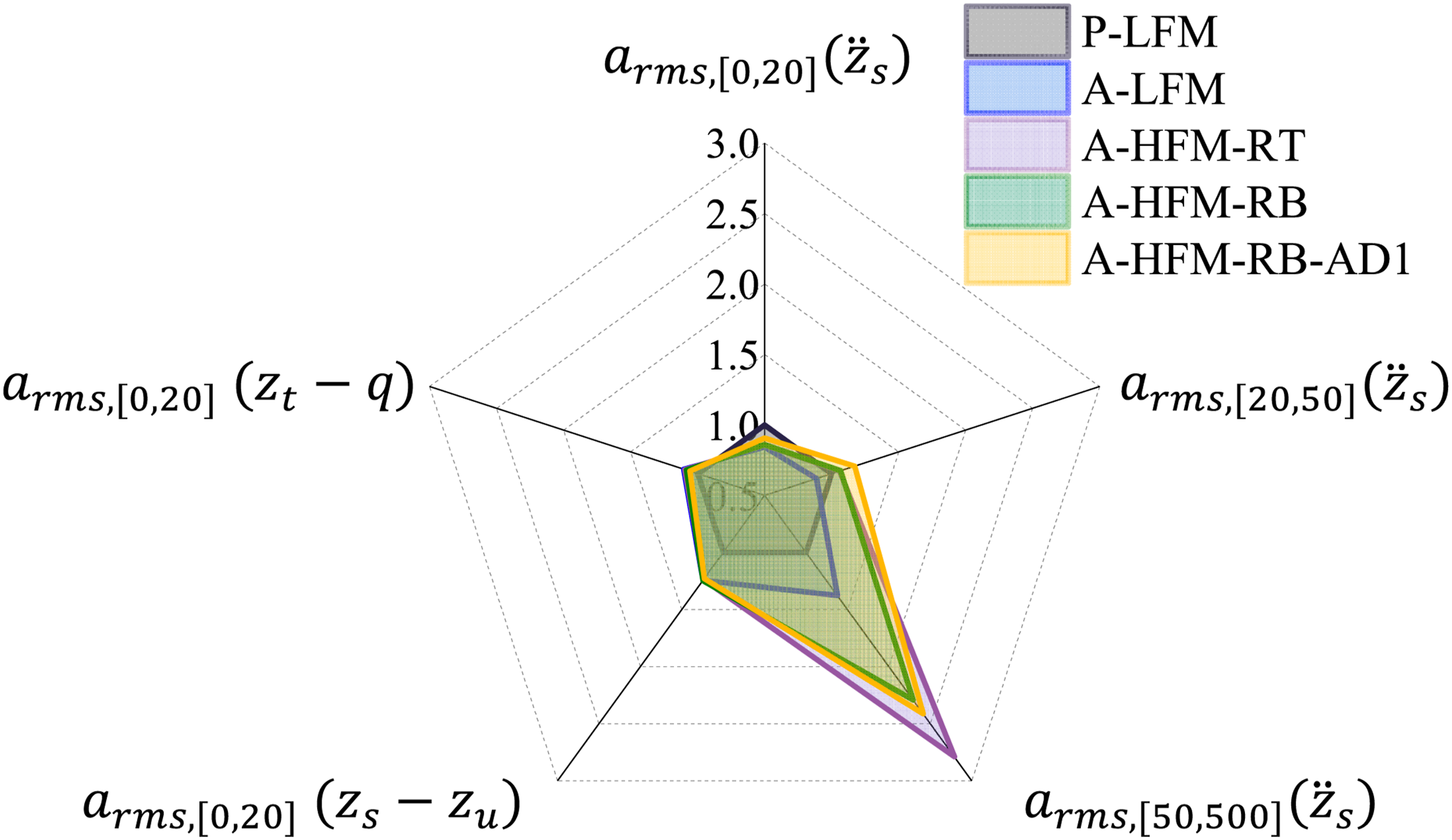
Figure 8 shows that active control significantly improves ride comfort in the 0–20 Hz band. It also slightly increases performance indices in higher-frequency bands due to variations in the control force. Incorporating a rigid ring has little impact on the 0–20 Hz band (<1.5%) but amplifies the 20–50 Hz and 50–500 Hz bands by 6.0% and 179.1%, respectively. Under active control, the amplification in the 20–50 Hz range decreases compared with the passive case, whereas the response above 50 Hz increases slightly. In contrast, the rubber bushing reduces the vibration response above 50 Hz by 17.8% because of its isolation effect. When actuator dynamics are included, vibration levels increase across all frequency ranges, particularly above 50 Hz.
Relocating the measured suspension deflection from z s −z u to z 0 −z u shifts the sensing location from the body side to the active side of the rubber bushing. Since z 0 is closer to the tire-suspension excitation source, this measurement contains stronger mid- and high-frequency vibration components, making the controller more sensitive to these structural vibrations. This explains the slight increase in the mid-frequency body acceleration response and suspension deformation (<1%). However, the rubber bushing still acts as a passive isolation element between z 0 and z s , attenuating the transmission of high-frequency vibration to the vehicle body. Consequently, the 50–500 Hz body acceleration response is reduced (−17.8%) despite the increased high-frequency content observed at the active side.
Figure 9 presents the PSD of vertical body acceleration. PSD results of body vertical acceleration for LFM, HFM-RT, HFM-RB, and HFM-RB-AD1.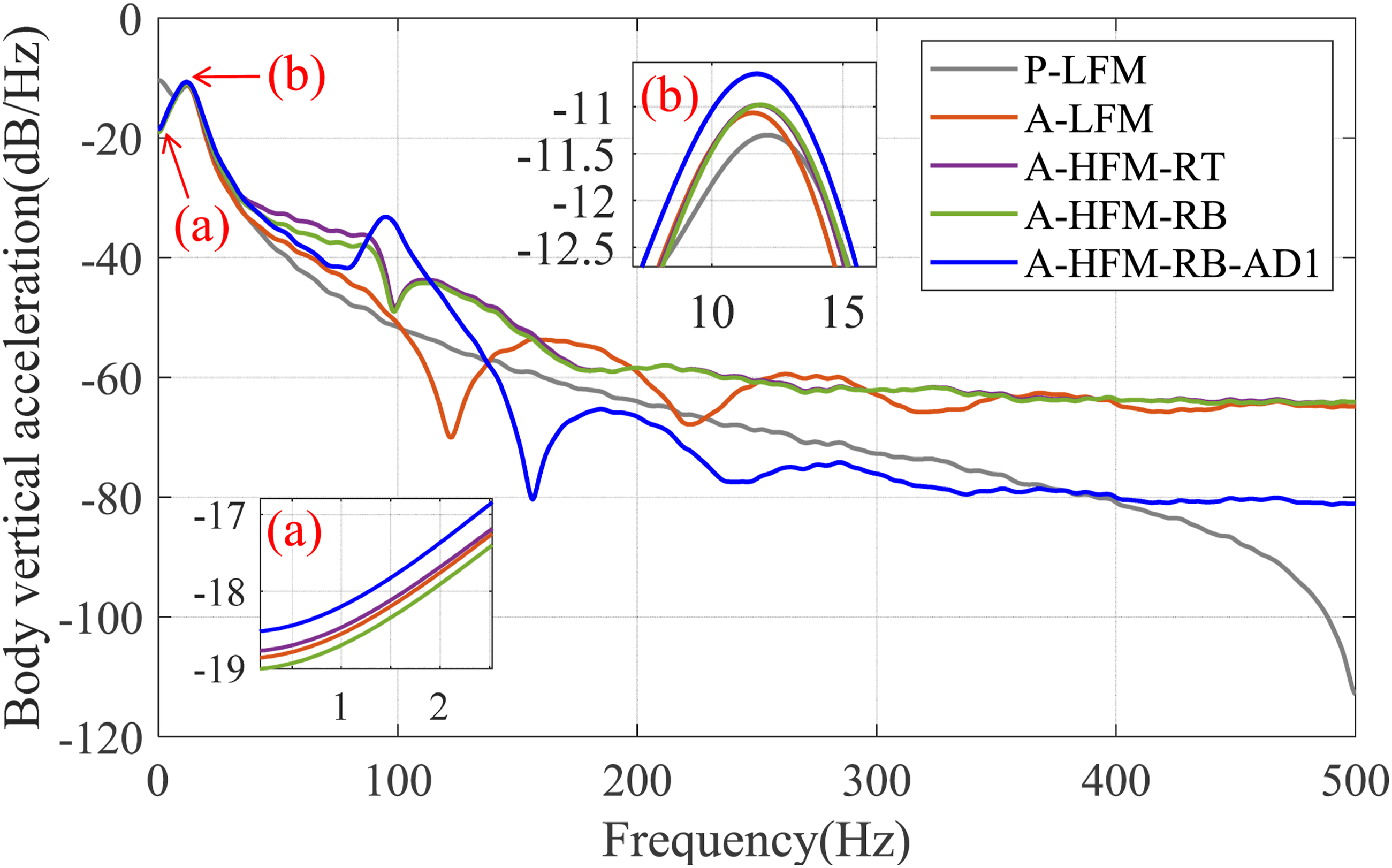
Figure 9(a) shows that the HFM-RB model achieves the best vibration suppression near the body natural frequency. After including first-order actuator dynamics, the HFM-RB-AD1 model exhibits degraded performance because of actuator response lag. Similar degradation is also observed near the unsprung-mass natural frequency in Figure 9(b). In the higher-frequency range, the HFM-RB-AD1 model shows a pronounced resonance peak near the rigid-ring mode, followed by rapid attenuation above 130 Hz. This behavior reflects the low-pass filtering effect introduced by the actuator dynamics, which suppresses vibration transmission at higher frequencies while reducing control effectiveness in lower frequency regions. Such behavior aligns with the approach in Collette and Preumont (2010), which utilized a pre-controller low-pass filter to mitigate high-frequency issues in semi-active systems.
The time-domain active control force is illustrated in Figure 10. Active control force of LFM, HFM-RT, HFM-RB, and HRM-RR-AD1.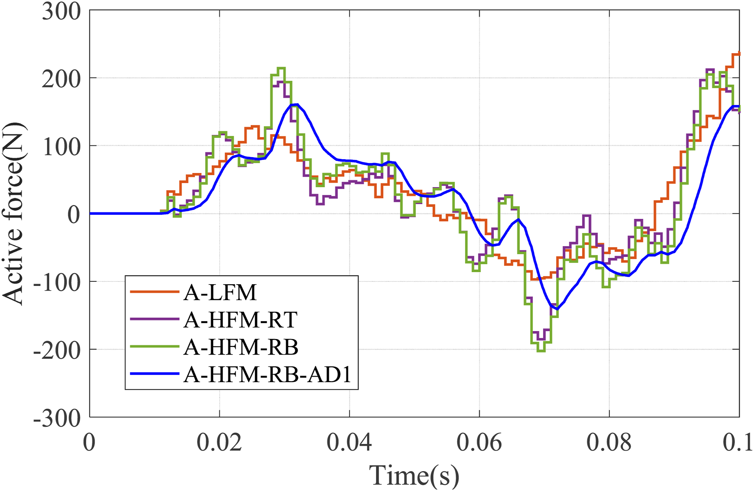
As depicted in Figure 10, the actuator output (in blue) exhibits a continuous force profile within the illustrated local time window. The actuator response delay contributes to the reappearance of the resonance peak associated with the rigid-ring mode observed in Figure 9. This delay also shifts the spectral fluctuations toward higher frequencies compared with other models.
Control effort and RMS force comparison.
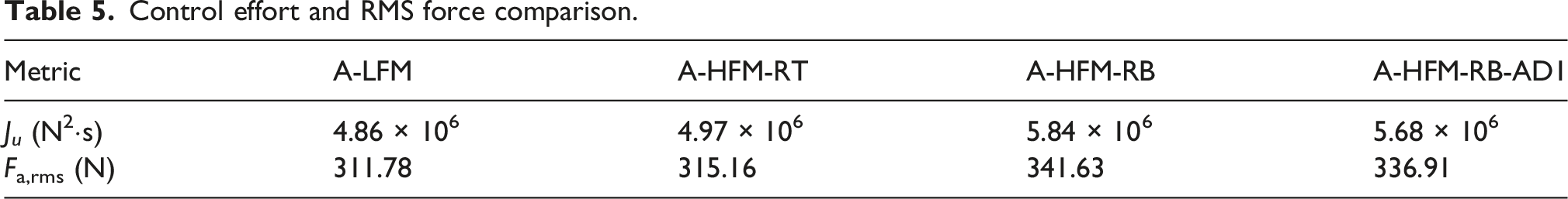
Compared with A-LFM, the HFM-RT model shows only a slight increase in control effort, whereas the HFM-RB model requires higher control effort because of the additional vibration transmission characteristics introduced by the rubber bushing. After including actuator dynamics, the A-HFM-RB-AD1 model exhibits a slightly lower J u than A-HFM-RB, indicating that the actuator dynamics attenuate part of the high-frequency control demand while introducing response lag. Moreover, the required active force remains within approximately ±1500 N throughout the simulation, with RMS force levels between 312 N and 342 N. These force levels remain within the typical operating range of automotive active suspension actuators and do not require unrealistically large actuator outputs.
4.2.3 Verification using an alternative controller
Comparison of vibration performance and control effort under different control frameworks.
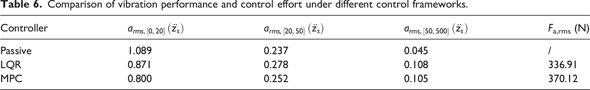
As shown in Table 6, both LQR and MPC significantly reduce vibration within the 0–20 Hz range compared with the passive suspension system. However, both controllers also increase the vibration response within the 20–50 Hz and 50–500 Hz ranges. Although MPC achieves slightly better low-frequency vibration suppression with a higher RMS control force, the amplification phenomenon in the higher-frequency ranges remains evident and exhibits a trend similar to that observed under LQR control. These results indicate that the high-frequency vibration characteristics discussed in this study mainly originate from the structural dynamics and finite actuator response of the suspension system rather than from a specific control strategy.
4.3 Influence of control frequency
As illustrated in Figure 6, the controller output is first subject to a system delay, then undergoes a discrete-to-continuous signal conversion before being transmitted to the actuator. Due to computational latency, the control signal may not be applied within the designated sampling period. Figure 11 presents the PSD of body vertical acceleration for a controller output frequency of 100 Hz. PSD results of body vertical acceleration for HFM-RB and HFM-RB-AD1 under different control frequencies.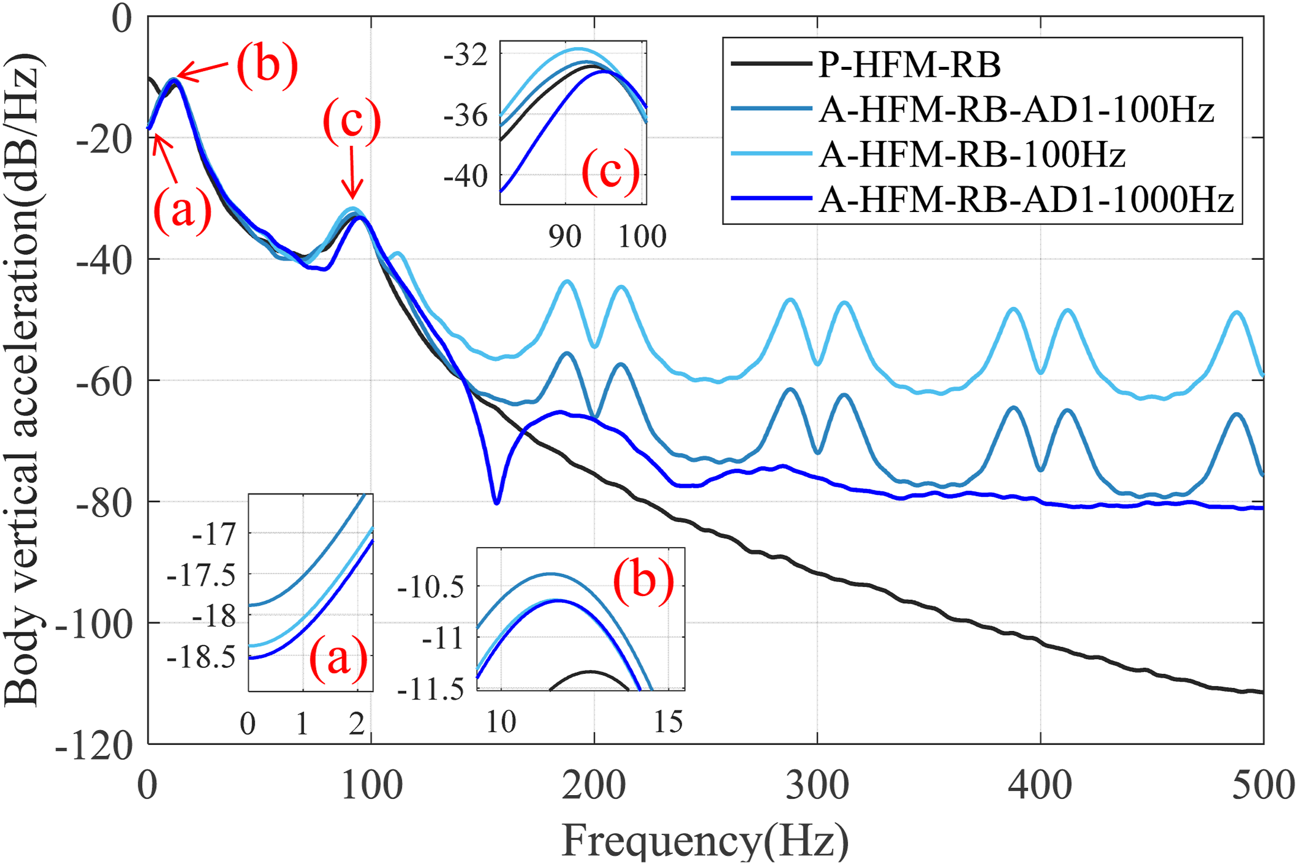
As demonstrated in Figure 11(a), as the control frequency decreases, the body comfort decreases. In sub-Figure 11(b), the main control signal frequency of 100 Hz resonates with the rigid-ring’s natural frequency, resulting in modal coupling at the non-sprung mass natural frequency. Consequently, the A-HFM-RB-AD1-100 Hz model exhibits the largest vibration response near the rigid-ring resonance compared with A-HFM-RB-AD1-1000 Hz. Similarly, in Figure 11(c), the control signal’s frequency resonates with the non-sprung mass’s natural frequency, leading to modal coupling at the rigid-ring’s mode. Multiple resonance peaks appear above 100 Hz, and their frequencies can be expressed as
These results indicate that the control frequency affects the vibration performance within the 0–20 Hz range and also induces additional structural vibration within the higher-frequency range. Such resonance behavior may further influence vibration transmission associated with structure-borne noise. It should also be noted that the resonance peaks above 100 Hz are obtained without considering higher-order tire elastic modes, such as the tire acoustic cavity mode around 200–230 Hz. Coupling between these tire modes and the structural resonances identified in this study may further increase vibration amplification in the higher-frequency range.
To reduce such coupling effects, the control frequency should avoid integer multiples of the dominant structural modes, including the rigid-ring and unsprung-mass modes considered in the present model. In addition, when the control frequency approaches the structural response range, modulation effects between the control signal and structural modes may generate unintended resonance peaks. Therefore, the control frequency should be set sufficiently away from the dominant modal frequencies or significantly higher than the highest frequency of interest.
5. Conclusion and future work
This study developed a dual-effect quarter-vehicle suspension model incorporating a rigid-ring tire and a strut-mount bushing to investigate the high-frequency structural vibration behavior of electronically controlled suspension (ECS) systems. The proposed model extends the conventional low-frequency quarter-vehicle framework to the 0–500 Hz range and is validated through road test measurements. In addition, a frequency-banded evaluation framework was established to analyze ECS behavior across the ride comfort, vibration-acoustic transition, and structure-borne noise frequency bands. Based on this framework, the influences of high-frequency structural components and control frequency were systematically investigated.
The results lead to several main conclusions. (1) The inclusion of rigid-ring tire and bushing dynamics significantly affects the high-frequency response of the suspension system, enabling the model to capture the transition from ride-comfort behavior to structure-borne vibration characteristics. The model also provides trend-level prediction capability for coupling effects above 100 Hz. (2) Comfort-oriented control strategies may unintentionally excite structural modes within the 50–500 Hz range due to step-like variations in control signals. Therefore, control frequencies should avoid structural modal frequencies or be selected sufficiently above the target frequency range. Overall, the proposed framework provides a reduced-order approach for analyzing ECS-induced structural vibration behavior across low- and high-frequency regions.
Despite its effectiveness, the current framework still has several limitations. The suspension system is modeled using linear spring-damper characteristics, and the tire is simplified using a rigid-ring representation. Future work will therefore focus on incorporating nonlinear suspension dynamics, flexible tire-rim interactions, and coupled structural-acoustic models to improve high-frequency modeling capability. Further experimental validation will also be conducted to support future investigations of ECS-related vibration and acoustic behavior.
Supplemental material
Supplemental material - A dual-effect quarter-vehicle model for structural-acoustic frequency band analysis of electronically controlled suspension
Supplemental material for A dual-effect quarter-vehicle model for structural-acoustic frequency band analysis of electronically controlled suspension by Zhehui Zhu, Lijun Zhang, Dejian Meng, and Siqi Chen in Journal of Vibration and Control
Footnotes
Funding
The authors disclosed receipt of the following financial support for the research, authorship, and/or publication of this article: This work was supported by National Natural Science Foundation of China (NSFC, Grant number: 52472415).
Declaration of conflicting interests
The authors declared no potential conflicts of interest with respect to the research, authorship, and/or publication of this article.
Supplemental material
Supplemental material for this article is available online.
References
Supplementary Material
Please find the following supplemental material available below.
For Open Access articles published under a Creative Commons License, all supplemental material carries the same license as the article it is associated with.
For non-Open Access articles published, all supplemental material carries a non-exclusive license, and permission requests for re-use of supplemental material or any part of supplemental material shall be sent directly to the copyright owner as specified in the copyright notice associated with the article.