
Abstract
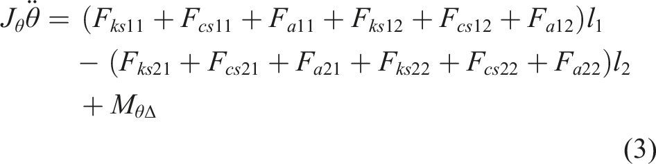
This article proposes a robust nonlinear control strategy for a full-vehicle active suspension system equipped with hydraulic actuators to improve ride comfort and enhance vehicle body stability under road disturbances, model nonlinearities, and lumped uncertainties. A seven-degree-of-freedom full-vehicle model is established, including heave, roll, and pitch motions of the sprung mass, vertical dynamics of the four unsprung masses, and hydraulic actuator dynamics, while nonlinear spring and damping characteristics are explicitly considered. To simultaneously guarantee heave, roll, and pitch stability with minimum actuator effort, an optimal active force allocation method based on the Moore–Penrose pseudo-inverse is introduced to distribute the generalized control forces among four independent hydraulic actuators. A cascade control structure is then developed, in which adaptive fixed-time sliding mode control (AFxTSMC), integrated with active disturbance rejection control (ADRC), is employed in the outer loop to generate the desired control force. At the same time, an inner-loop proportional–integral–derivative (PID) controller regulates the hydraulic servo valve for accurate force tracking. Lyapunov stability analysis is performed to verify the boundedness of all closed-loop signals and the fixed-time convergence of the tracking errors. Comparative simulations under sinusoidal and random road excitations are conducted against PID-ACO, ADRC, and SM-DRC methods. Under sinusoidal excitation, the proposed controller achieves the lowest root mean square (RMS) vertical body acceleration of 0.014 m/s2, corresponding to reductions of approximately 17.6%, 26.3%, and 75.0% compared with SM-DRC, ADRC, and PID-ACO, respectively. Under random road excitation, the vibration dose value (VDV) decreases to 0.506 m/s1.75, representing improvements of 35.5%, 39.9%, and 85.2% over SM-DRC, ADRC, and PID-ACO, respectively. Furthermore, the roll and pitch angles are effectively constrained to 0.012° and 0.003°, demonstrating the robustness of the proposed control strategy under complex operating conditions.
Keywords
1. Introduction
The suspension system plays a crucial role in automotive engineering by improving ride comfort, maintaining tire–road contact, and enhancing vehicle handling stability. With the continuous development of intelligent transportation and modern vehicle dynamics control, suspension systems have gradually evolved from conventional passive structures to advanced semi-active and fully active control configurations. A conventional suspension system consists of elastic elements (such as coil springs, leaf springs, or torsion bars), damping elements, and guiding mechanisms (such as upper and lower control arms or multi-link bars), commonly referred to as a passive suspension system. Since passive suspension systems cannot generate active control forces to suppress vehicle body vibrations, their performance is inherently limited under varying driving conditions.
Nowadays, many suspension systems are integrated with actuators capable of automatic control. Typical examples include air suspension systems, where air springs replace conventional metal springs (Tan et al., 2024), semi-active suspension systems employing magnetorheological dampers (Gad et al., 2024), and hybrid suspension configurations combining air suspension with semi-active damping mechanisms (Xiao et al., 2018). However, these advanced suspension systems still face limitations in control performance, adaptability, and investment cost. Active suspension systems equipped with independent actuators to actively suppress vehicle body vibrations are considered a promising solution for improving ride comfort (Kumar and Rana, 2023). These systems may employ hydraulic actuators (Nguyen, 2025) or electromagnetic actuators based on linear motors (Zhao S et al., 2023a), which can be arranged separately alongside conventional springs and dampers or integrated with in-wheel motors in modern electric vehicles (Jin et al., 2023).
In addition to vibration suppression for ride comfort improvement, active suspension systems also provide significant benefits in maintaining vehicle stability. Yao et al. (2020) investigated an active suspension control strategy to reduce the roll angle during J-turn steering maneuvers. Chen et al. (2023) introduced a controllable suspension system capable of generating the desired anti-roll moment to enhance roll stability. An application of active suspension for improving both vertical and pitch stability was presented in Pang et al. (2018). Besides ride comfort enhancement, the criteria of road holding and vehicle handling must also be guaranteed, as emphasized by Flayyih et al. (2023). However, achieving a balance among these performance objectives is not straightforward, and in many cases, trade-offs are unavoidable to optimize specific criteria (Nguyen, 2023). Therefore, most existing studies on suspension control focus primarily on quarter-car or half-car models (heave–pitch or heave–roll) with relatively simple active force allocation strategies.
Proportional–integral–derivative (PID) control is a classical control method for simple linear systems with a single-input single-output (SISO) structure. Nguyen (2021a) designed a dual-control mechanism using two PID controllers, one for vertical displacement regulation and the other for vertical acceleration control. The calculation results showed that a signal oscillation occurred due to the interaction between the two controllers. Mahmoodabadi and Nejadkourki (2020) developed an adaptive PID controller by tuning the control parameters using a fuzzy rule optimized by particle swarm optimization (PSO), which demonstrated improved chassis acceleration compared with several conventional control methods. A cascade PID control structure with multiple loops for four independent actuators was proposed in Dahunsi et al. (2019), where the controller parameters were optimally determined using Global and Evolutionary techniques. However, their work did not discuss the problem of optimal active force distribution among the individual actuators. Gampa et al. (2022) developed a Grasshopper Optimization Algorithm based on the Pareto-optimal technique to determine optimal PID control parameters. Their results showed that the proposed method converged faster than the conventional genetic algorithm (GA). A parameter-optimization approach based on a back propagation neural network (BPNN) integrated with the sparrow search algorithm (SSA) was presented in Li et al. (2024) to enhance the tuning capability of PID controllers across different operating conditions. In addition, Li and Shi (2024) introduced an adaptive endocrine PID controller based on reinforcement learning to overcome the limitations of conventional tuning methods. Several applications of GA and adaptive fuzzy logic for tuning the parameters of fractional-order PID (FOPID) controllers were also discussed in Swethamarai and Lakshmi (2020) and Yin et al. (2024), showing noticeable improvements in suspension performance. Although the structures of PID and FOPID controllers are relatively simple and easy to implement, they are generally unsuitable for multi-input multi-output (MIMO) systems. Moreover, these control approaches are mainly effective for simple linear systems. They are not sufficiently robust when adverse factors such as road disturbances, lumped uncertainties, and model nonlinearities are considered.
Control methods based on the linear quadratic regulator (LQR) theory provide strong potential for application in MIMO suspension systems (Nguyen and Iqbal, 2025). Nagarkar et al. (2018) developed an LQR controller whose parameters were optimized using a GA across multiple performance criteria, including root mean square (RMS) acceleration, vibration dose value (VDV), and RMS suspension travel. However, this approach can be considered an indirect control strategy, as the influence of actuator dynamics was not explicitly accounted for. Zhao and Gu (2023) employed a hybrid PSO-GA technique to optimize the weighting matrices
Several robust control strategies have also been developed for active suspension systems. Wang et al. (2015) designed a robust fault-tolerant control scheme based on the H∞ framework for an active suspension model with finite-frequency constraints. However, their study mainly focused on the comparison between active and passive suspension systems, while comparisons with other advanced control strategies were not extensively discussed. An application of robust finite-frequency H∞ control for suspension systems was presented in Jing et al. (2018), where the influence of uncertainties was considered, and vibration performance was evaluated within the frequency range of 4–8 Hz. Chen et al. (2018) developed a robust H∞ control strategy for a nonlinear suspension model. Their results mainly emphasized frequency-domain evaluation, while the time-domain dynamic responses could be further discussed to provide a more comprehensive performance assessment. Afshar et al. (2023) proposed an H2/H∞ controller considering external disturbances and parametric uncertainties, combined with Lyapunov stability analysis and Linear Matrix Inequality techniques. Although ride comfort, suspension travel limits, and road-holding capacity were considered in the controller design, the influence of hydraulic actuator dynamics was not discussed in detail. Several other applications of robust H∞ control have also demonstrated certain effectiveness in suspension regulation (Afshar et al., 2018; Li et al., 2019; Shi et al., 2023). In general, however, H∞-based methods still face challenges related to conservative controller design, complex parameter tuning, and limited adaptability when dealing with strong nonlinearities, actuator dynamics, and rapidly varying uncertainties in practical suspension systems.
Sliding mode control (SMC) provides strong robustness against disturbances and system uncertainties, making it a promising approach for active suspension applications. Nguyen (2021b) developed a conventional SMC strategy for an active suspension model with a linearized hydraulic actuator, showing improvements in ride comfort; however, the unsprung mass displacement and acceleration remained relatively large. Bai and Wang (2021) combined SMC with LQR to handle parametric uncertainties and external disturbances, although the reduction in vehicle body acceleration was only moderate compared with the conventional LQR method. Wang et al. (2020) integrated Terminal Sliding Mode Control with an adaptive disturbance observer to address the nonlinear suspension dynamics by designing a fast-converging sliding surface. Liu and Pan (2020) combined a barrier function with the SMC law to guarantee finite-time convergence without requiring prior knowledge of uncertainty bounds. Their results showed clear performance improvement and strong practical applicability, although the chattering effect remained. A control algorithm combining backstepping and SMC for quarter-car suspension dynamics with actuator delay was presented in Gu et al. (2022), demonstrating better convergence performance than the conventional H∞ method. However, the resulting control force remained relatively small, which may limit its effectiveness under severe practical operating conditions. Several other applications of SMC for improving ride comfort and ensuring road holding were discussed in Nguyen (2024) and Wijaya et al. (2024), indicating its potential under specific operating scenarios. In addition, several cascade or multi-layer control structures have been developed to enhance suspension performance further. For instance, LQR has been used to generate the reference signal for an inner-loop SMC controller (Zhao Z et al., 2023b). In another approach, SMC was employed to generate the desired reference signal to improve vehicle stability, and an adaptive PID controller was subsequently used to produce the actual control input for the hydraulic suspension actuator (Moradi and Fekih, 2013). Similarly, a fuzzy super-twisting sliding mode control (STSMC) strategy was designed to generate the reference signal based on vehicle dynamic performance improvement, and the resulting signal was then supplied to a PID controller whose parameters were optimally tuned using Ant Colony Optimization for actuator control in the suspension system (Zahra and Abdalla, 2020). In general, SMC offers significant advantages in robustness, fast convergence, and strong disturbance rejection. However, it still faces several limitations, particularly chattering, sensitivity to parameter selection, and difficulty maintaining high control performance when actuator dynamics, strong nonlinearities, and multiple coupled suspension objectives must be considered simultaneously.
Recent studies have reported significant advances in robust control techniques for uncertain nonlinear systems. Fixed-time equivalent-input-disturbance estimation methods have been developed to enhance disturbance rejection performance by enabling fast disturbance reconstruction and compensation, thereby improving robustness against lumped uncertainties and external disturbances (Lu et al., 2024). In addition, adaptive gain-scheduled STSMC approaches integrated with ESOs have been proposed to compensate for disturbances and unmodeled dynamics while reducing chattering through online gain adaptation (Wang et al., 2025). For vehicle suspension applications, robust fuzzy SMC frameworks have also been investigated for nonlinear full-vehicle systems under parameter variations and lumped uncertainties, demonstrating improved ride comfort and road-holding performance (Emami et al., 2025). These studies highlight the effectiveness of combining disturbance estimation, adaptive gain tuning, and robust SMC for complex, uncertain systems.
Recent advances in SMC have focused on improving robustness, reducing computational burden, and enhancing implementation efficiency. For instance, a data-driven, adaptive event-triggered terminal SMC combined with prescribed performance functions has been proposed to achieve finite-time bounded tracking while reducing unnecessary control updates (Echreshavi et al., 2025). Observer-based and disturbance-observer-assisted integral SMC strategies have also been developed to improve disturbance rejection and reduce chattering effects under event-triggered implementations (Echreshavi et al., 2023). Furthermore, fuzzy event-triggered integral SMC approaches have been investigated for nonlinear systems with external disturbances, providing robustness while reducing communication and computation requirements (Echreshavi et al., 2021). To address practical implementation constraints, dynamic-observer-based fuzzy-integral SMC schemes incorporating input magnitude and rate limitations have also been reported (Echreshavi et al., 2020). Although these studies have demonstrated promising performance in their respective applications, the combined integration of adaptive finite-time sliding mode control, ADRC-based disturbance estimation, hydraulic actuator dynamics, and optimal force allocation for nonlinear full-vehicle active suspension systems remains relatively underexplored.
1.1. Research gaps and key contributions
Despite considerable progress in active suspension control research, several important limitations remain in existing literature. First, most suspension studies are based on quarter- or half-car models, which are relatively simple and cannot fully represent the coupled dynamic behavior of a full-vehicle system, especially the simultaneous interactions among heave, roll, and pitch motions. As a result, the overall vehicle stability under complex road excitations cannot be comprehensively evaluated.
Second, the dynamics of hydraulic actuators and the nonlinear characteristics of the suspension system are often simplified or only partially considered. In many practical applications, actuator dynamics, fluid compressibility, valve flow characteristics, and suspension nonlinearities significantly affect control performance and cannot be neglected. Third, the influence of parameter uncertainties and external disturbances is often ignored or insufficiently addressed, which may reduce the controller’s robustness and reliability under real operating conditions.
In addition, although several studies have considered full-vehicle suspension models, the problem of optimal active force distribution among multiple independent actuators has not been clearly discussed. In many cases, the generalized control forces are assigned directly without a systematic allocation strategy, which may result in unnecessary actuator overload and reduced control efficiency. Furthermore, conventional control algorithms such as PID, LQR, H∞, and standard SMC still suffer from limitations related to weak robustness against strong nonlinearities, difficulty in handling multiple coupled objectives, conservative parameter tuning, or chattering effects.
To address these research gaps, this paper proposes a robust nonlinear control framework for a full-vehicle active suspension system with hydraulic actuators. The main contributions of this study are summarized as follows: • First, a full-vehicle dynamic model is established to comprehensively describe the heave, roll, and pitch motions of the sprung mass, together with the vertical dynamics of the four unsprung masses. The nonlinear characteristics of the suspension system are explicitly considered, including nonlinear spring stiffness, nonlinear damping behavior, and the complete hydraulic actuator dynamics. • Second, both road disturbances and lumped uncertainties are fully incorporated into the mathematical model and controller design. This allows the proposed method to represent practical operating conditions better and improves the robustness of the suspension control system against modeling errors and external excitations. • Third, an optimal active force allocation strategy based on the Moore–Penrose pseudo-inverse is proposed to distribute the generalized control forces among the four hydraulic actuators. This method minimizes overall actuator effort while ensuring effective heave, roll, and pitch stability. • Finally, a cascade control structure is developed in which the outer-loop controller employs adaptive fixed-time sliding mode control (AFxTSMC) combined with active disturbance rejection control (ADRC) to generate the desired generalized control forces and reference actuator signals. In contrast, the inner-loop PID controller regulates the hydraulic servo valve to ensure accurate force tracking of the actuator system. This integrated strategy improves convergence speed, disturbance rejection capability, and practical implementation performance for full-vehicle active suspension control.
The remainder of this article is organized as follows. Section 2 presents the mathematical modeling of the full-vehicle active suspension system, including suspension dynamics, a hydraulic actuator model, an optimal active force allocation strategy, controller design, and stability analysis. Section 3 provides the simulation studies and discusses the comparative results under sinusoidal and random road excitation conditions. Finally, Section 4 summarizes the main conclusions of this work and outlines potential directions for future research.
2. Mathematical model and control design
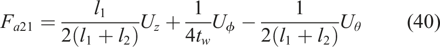
This section presents the dynamic modeling of the full-vehicle active suspension system, including the vertical, roll, and pitch motions of the sprung mass, as well as the dynamics of the hydraulic actuators. Based on the developed mathematical model, an optimal force-allocation strategy is introduced to distribute the generalized control forces among the four suspension actuators. Finally, the proposed AFxTSMC–ADRC control scheme is designed to improve ride comfort and enhance vehicle body stability under various road disturbances and system uncertainties.
2.1. Full-vehicle suspension model
A full-vehicle suspension model with seven degrees of freedom is illustrated in Figure 1. The dynamic equation of the sprung mass in the vertical (heave) direction is expressed in (1) as follows: Vehicle dynamics model.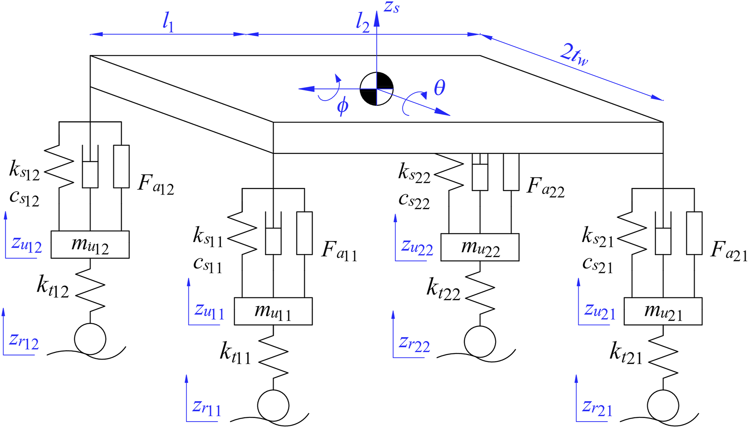
The roll and pitch dynamic behaviors of the sprung mass are described by (2) and (3), respectively,
The dynamic behaviors of the unsprung masses are described by (4)–(7) as follows:


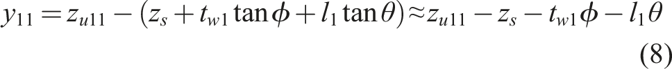
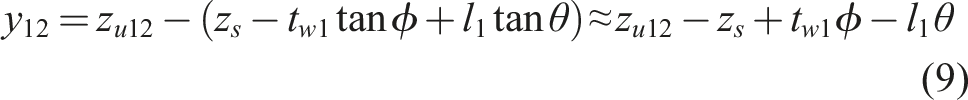
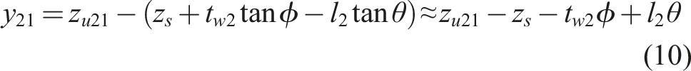
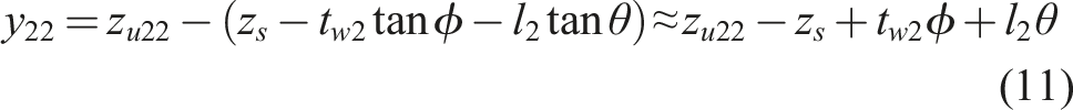
The suspension travel (y) is defined by (8)–(11). The approximation expressions are obtained under the assumption that the roll and pitch angles are sufficiently small.


Similarly, the suspension damping force (F
cs
) is determined by (16)–(19),


The tire spring force (F
kt
) is determined by the tire stiffness (k
t
) and the road excitation (z
r
), as described in (20)–(23). The tire force is modeled as a linear elastic force proportional to the relative displacement between the road profile and the unsprung mass displacement. In this study, tire damping is neglected in the tire dynamics model.


The active control force is generated by the pressure difference between the two chambers of the hydraulic actuator, as described by (24),

The fluid dynamics inside the hydraulic cylinder are represented by (25) and (26). Equation (25) describes the load pressure dynamics, which are governed by hydraulic flow rate, fluid compressibility, actuator motion, and internal leakage. Equation (26) represents the servo valve flow equation, where the valve spool displacement and the pressure difference across the valve orifice determine the flow rate.
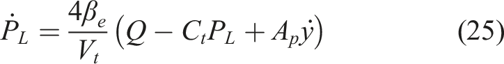

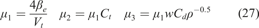
By defining the auxiliary parameters in (27) and substituting (26) and (27) into (25), the load pressure dynamics can be rewritten in the simplified form shown in (28).

The spool valve dynamics are modeled as a first-order system, as presented in (29), where τ denotes the servo valve time constant, k
v
is the valve gain coefficient, and u represents the control voltage input applied to the servo valve.

2.2. Optimal active force allocation
To generate the desired generalized control forces for the heave, roll, and pitch motions while minimizing the overall actuator effort, an optimal force allocation strategy based on the minimum-norm criterion is employed.
The actuator force vector is defined as in (30):

The generalized control inputs associated with the heave, roll, and pitch motions are expressed by (31).


Equations (32)–(34) can be reformulated into the following compact matrix form:
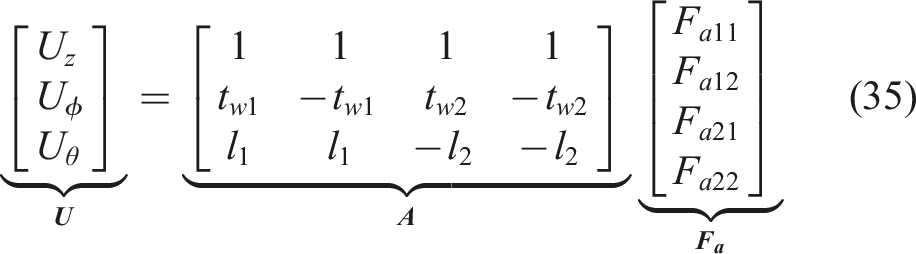
Since the system contains four active forces but only three generalized control objectives, the force allocation problem is underdetermined and admits infinitely many feasible solutions. Therefore, the minimum-norm optimization criterion is adopted to determine the unique optimal solution with minimum total actuator effort by minimizing (36) subject to the equality constraint in (35).

The optimal solution is obtained using the Moore–Penrose pseudo-inverse as in (37).

After substitution and simplification, the optimal actuator forces are derived by equations (38) to (41).
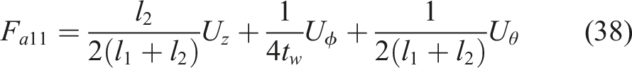
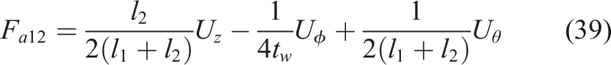
It can be verified that the obtained forces satisfy all three generalized control requirements exactly while ensuring minimum total actuator energy. This allocation strategy guarantees balanced force distribution among the four suspension actuators and avoids unnecessary excessive control effort, thereby improving both control efficiency and actuator durability.
The Moore–Penrose pseudo-inverse provides a computationally efficient minimum-norm solution for real-time force allocation among the four suspension actuators. It should be noted that the current allocation scheme assumes full actuator availability and does not explicitly account for actuator saturation or faults. Under severe actuator constraints, the allocation performance may degrade because the pseudo-inverse solution does not enforce input bounds. Nevertheless, the proposed framework can be extended in future studies by incorporating constrained optimization or fault-tolerant allocation strategies to account for actuator limitations and failures explicitly.
2.3. Control design
In this article, a robust nonlinear control scheme integrating AFxTSMC and ADRC is developed to improve the control performance of the full-vehicle suspension system, accounting for the effects of hydraulic actuator dynamics. The overall structure of the proposed control system is illustrated in Figure 2. Proposed control system.
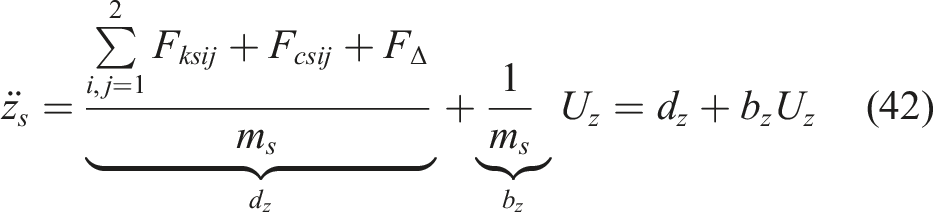
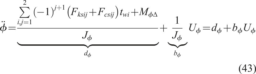
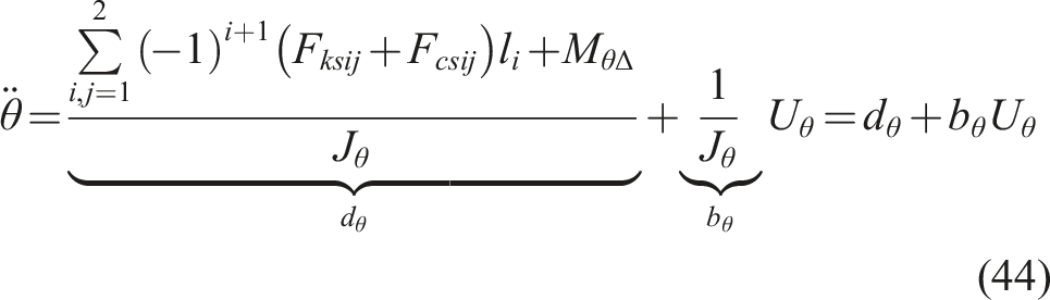
By substituting (32), (33), and (34) into (1), (2), and (3), respectively, the heave, roll, and pitch dynamic equations can be rewritten as (42), (43), and (44).
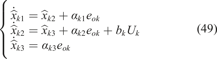
The system’s dynamic states are estimated using an extended state observer (ESO), a key component of the ADRC structure, rather than being directly measured by physical sensors. The state variables of the heave, roll, and pitch subsystems are arranged in the order of appearance as defined in (45), (46), and (47), respectively.


Let e
ok
denote the observation error, which is defined by (48), where the subscript k represents z (heave), ϕ (roll), and θ (pitch), respectively.

The observer dynamics are described by (49),
The tracking error (e
k
) is defined in (50). Taking the second derivative of the tracking error yields (51).


The disturbance rejection control rule is proposed as in (52),
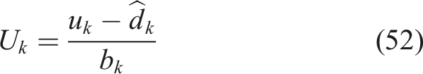
By substituting (52) into (51), (53) is obtained.

A terminal sliding surface (s
k
) is defined as in (54),

Taking the time derivative of the sliding surface and combining it with (53) yields (55).
The fixed-time sliding mode control law is proposed by (56),
By substituting (56) into (55), (57) is obtained.
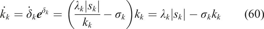
An adaptive law automatically tunes the control gain (k
k
) in the proposed fixed-time sliding mode controller, enabling the controller to adjust its control effort in response to variations in the system state and disturbances. This mechanism improves robustness while avoiding excessive control input due to overly high fixed gains. The structure of the proposed adaptive law is presented in (58) and (59).

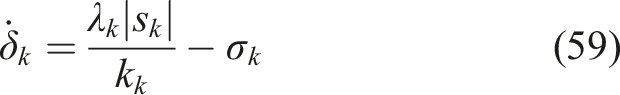
Taking the derivative of (58) and combining it with (59) yields (60).
2.4. Stability analysis
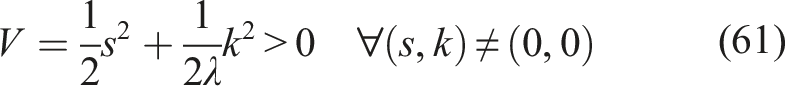
In this study, the stability of the proposed control system is analyzed using Lyapunov stability theory to guarantee the boundedness of all closed-loop signals and to ensure the convergence of the tracking errors within a fixed time. By accounting for model uncertainties, external disturbances, and hydraulic actuator dynamics, the stability proof shows that the proposed AFxTSMC–ADRC scheme maintains robust performance under practical operating conditions.
The Lyapunov candidate function V is selected by (61).
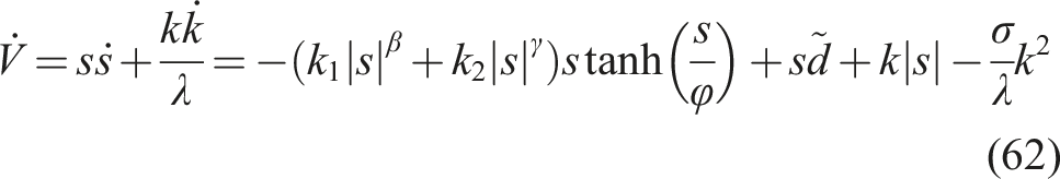
The time derivative of V in (62) is obtained by combining the derivative of (61) with (57) and (60).
To facilitate the stability analysis, the following properties of the hyperbolic tangent function are employed as in (63).
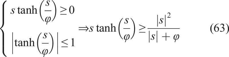

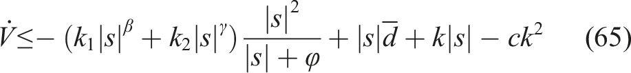
By substituting the conditions in (63) and (64) into (62), the inequality (65) can be obtained,
Applying Young’s inequality to the term k|s|, the following relation is obtained,
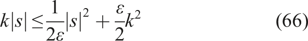
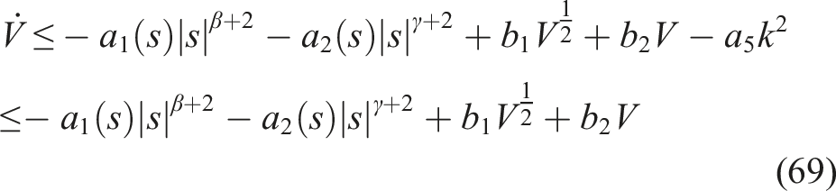
Substituting (66) into (65) yields (67). To ensure a5 > 0, ε should be selected such that ε < 2c.
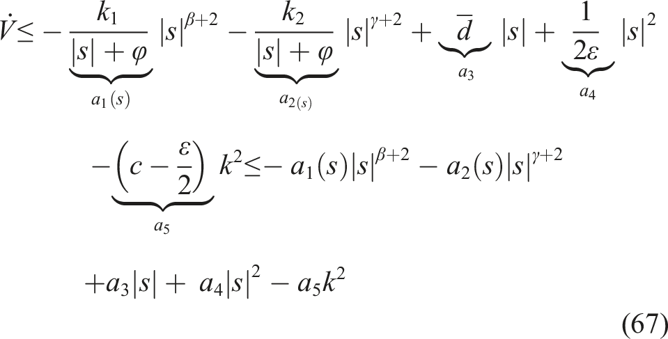
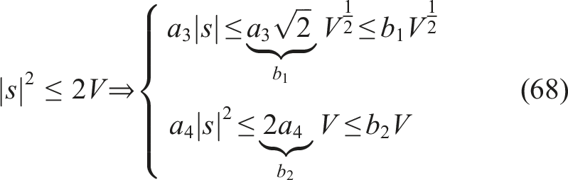
From the Lyapunov function in (61), it follows that |s|2 ≤ 2V. Based on this relation, the disturbance-related term and the quadratic state term can be further bounded as shown in (67). These inequalities are introduced to transform the derivative of the Lyapunov function into a standard form suitable for fixed-time stability analysis.
The controller parameters were selected according to the stability requirements of the proposed AFxTSMC framework and subsequently refined through iterative simulation studies. Specifically, the coefficients ck1 and ck2 were employed to shape the sliding surface dynamics and regulate the convergence behavior of the tracking error. The observer gain (α k ) was selected to ensure satisfactory disturbance estimation performance, whereas the exponent (β k ) determined the nonlinear characteristics of the sliding surface. The control exponent (γ k ) was introduced to enhance the finite-time convergence properties of the control law. The boundary layer parameter (φ k ) was chosen to mitigate chattering while preserving tracking accuracy. In addition, the adaptive coefficients (λ k ) and (σ k ) in the adaptive laws (59) and (60) were adjusted to achieve a suitable balance between adaptation speed and control smoothness. The final parameter values were selected to simultaneously improve ride comfort, suppress vehicle body motions, and maintain reasonable control effort. Moderate parameter perturbations mainly influenced the convergence speed and control activity, while the overall closed-loop stability and tracking performance remained preserved under the considered operating conditions.
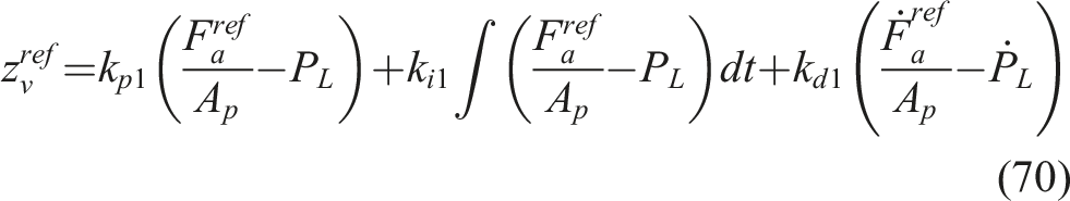
To ensure that the hydraulic actuator accurately tracks the desired control force generated by the outer-loop controller, a cascade control structure is introduced. In this configuration, the force-tracking objective is first transformed into a reference signal for the servo valve spool displacement. Specifically, the desired spool valve displacement is generated by a PID-based force-tracking controller, as formulated in (70), which regulates the pressure-related force error to achieve the desired actuator force. This stage establishes the connection between the generalized control force command and the internal hydraulic pressure dynamics.
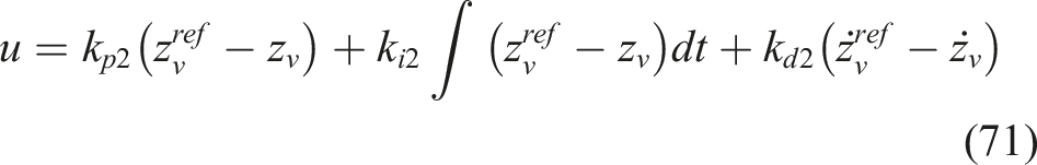
Subsequently, an inner-loop PID controller is employed to force the actual spool valve displacement to follow the reference signal, as described in (71). This inner-loop control improves the dynamic response of the hydraulic actuator and enhances tracking accuracy under nonlinear hydraulic effects and parameter uncertainties,
The cascade control architecture was designed according to a time-scale separation principle. Specifically, the inner-loop PID controllers responsible for force tracking and valve regulation were tuned to exhibit significantly faster dynamics than the outer-loop AFxTSMC–ADRC controller. Consequently, the hydraulic actuator subsystem can be approximated as a stable, fast inner process from the perspective of the outer-loop suspension controller. It should be noted that the stability analysis presented in this study primarily focuses on the AFxTSMC–ADRC outer-loop dynamics, while the hydraulic actuator and PID controllers are treated as stable inner-loop subsystems operating under the time-scale separation assumption. This bandwidth separation helps reduce loop interaction and contributes to stable cascade operation under the considered road excitation conditions. A more detailed frequency-domain analysis of the overall cascade architecture, including robustness margins under high-frequency excitations, is recognized as an important topic and will be further investigated in future studies.
Based on the proposed mathematical model, control strategy, and stability analysis presented above, simulation studies are conducted in the next section to evaluate the effectiveness and robustness of the proposed AFxTSMC–ADRC suspension control scheme under various road excitation conditions.
3. Simulation results
Numerical simulations are conducted to evaluate the performance of the proposed control strategy and compare it with several existing methods, including PID-ACO, ADRC, and SM-DRC. Two simulation scenarios are considered based on the road excitation profiles shown in Figure 3(a): a sinusoidal road excitation for the first case and a random road excitation corresponding to the ISO 8608 D-class road profile for the second case. The vehicle speed is set to v = 36 km/h. Simulation conditions. (a) Road disturbances; (b) lumped heave uncertainty; (c) lumped roll uncertainty; (d) lumped pitch uncertainty.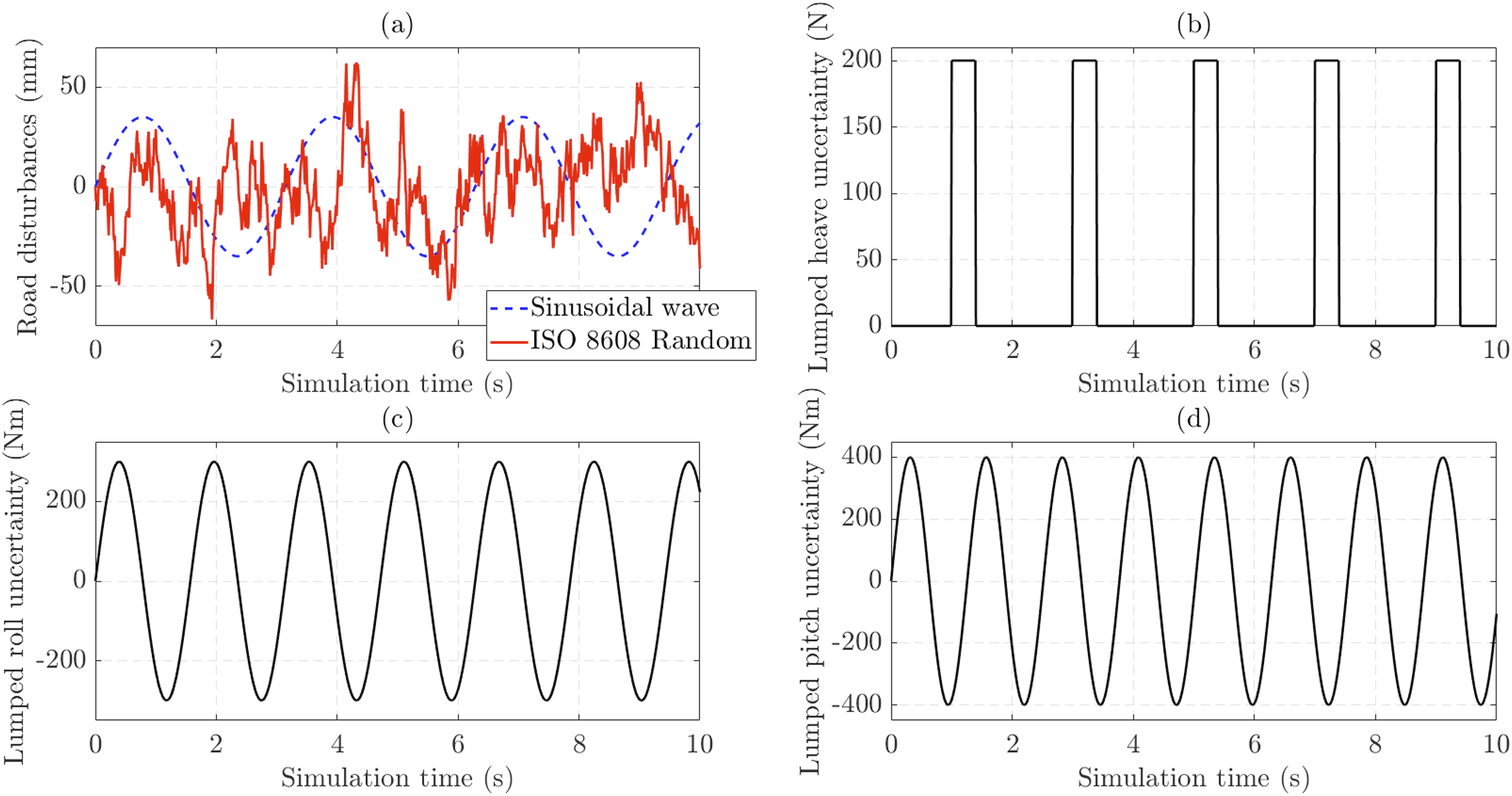
In the simulation, the road disturbance is first applied to the front-left wheel (zr11) and then transmitted to the rear-left wheel (zr21) based on the vehicle’s longitudinal delay due to the wheelbase and traveling speed. This time-delay relationship is expressed by (72).
The lumped heave uncertainty is modeled as sudden external disturbances in the form of rectangular pulse excitations, as illustrated in Figure 3(b). Meanwhile, the effects of the lumped roll and pitch uncertainties are represented by sinusoidal disturbances with different amplitudes and frequencies, as shown in Figures 3(c) and (d), respectively. These uncertainties are accounted for in both simulation scenarios to assess the robustness of the proposed control strategy under practical operating conditions.
The adopted lumped uncertainty profiles were selected to emulate several practical sources of modeling errors and external disturbances encountered in vehicle suspension systems. Specifically, the rectangular uncertainty acting on the heave dynamics can be interpreted as representing abrupt payload variations, road-induced load transfers, or changes in vehicle operating conditions. In contrast, the sinusoidal uncertainties introduced in the roll and pitch channels are intended to approximate persistent disturbances associated with tire wear, suspension component aging, parameter variations, and other slowly varying effects. Although simplified, these uncertainty profiles provide a practical framework for evaluating the robustness of the proposed controller against both transient and persistent disturbances. Related studies have also investigated adaptive prescribed-time control strategies under non-vanishing uncertainties, highlighting the importance of maintaining satisfactory tracking performance in the presence of persistent uncertainty bounds (Luo et al., 2024).
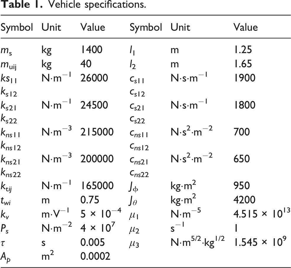
Vehicle specifications.
3.1. Performance under sinusoidal road excitation
The heave dynamic behaviors under sinusoidal road excitation are presented in Figure 4. As shown in Figure 4(a), the largest vehicle body displacement is observed with the PID-ACO controller, reaching 0.694 mm, which is significantly higher than those obtained with the SM-DRC (0.455 mm) and ADRC (0.365 mm) controllers. In terms of RMS performance, the sprung mass displacement achieved by PID-ACO, SM-DRC, and ADRC are 0.394 mm, 0.291 mm, and 0.171 mm, respectively. Heave dynamics behaviors (sinusoidal wave road excitation). (a) Vehicle body motion; (b) vehicle body acceleration.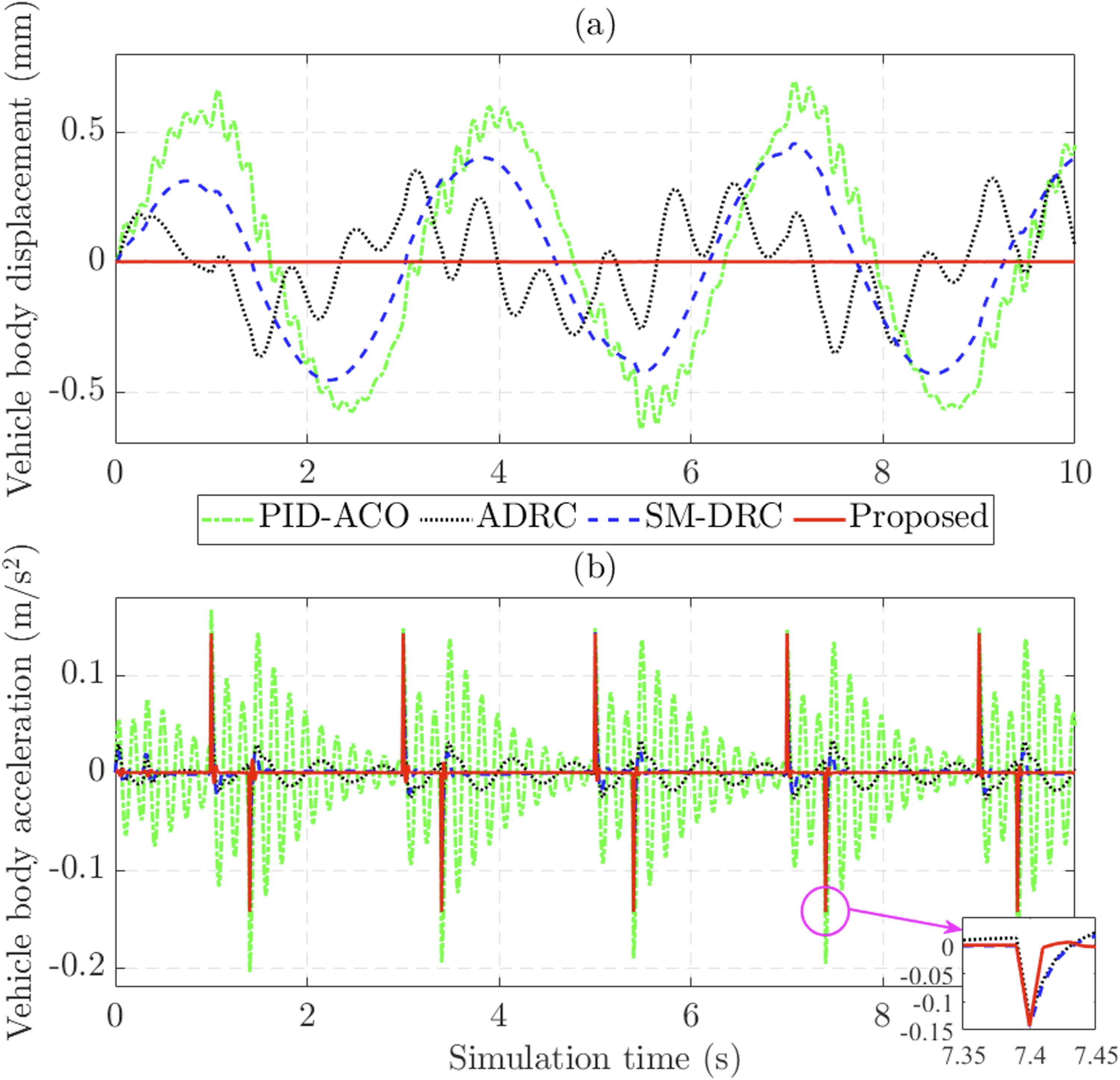
The proposed control strategy demonstrates a remarkable improvement over conventional control methods. The maximum vehicle body displacement is reduced to only approximately 0.002 mm, while the RMS value is around 0.0002 mm. In addition, the influence of the lumped heave uncertainty is almost eliminated under the proposed controller, whereas its effect remains clearly visible in the responses of PID-ACO and ADRC.
Ride comfort is further evaluated through the variation of vertical body acceleration. The results in Figure 4(b) show that the largest body acceleration occurs when the suspension system is controlled by the PID-ACO method, with a peak value of 0.205 m/s2 and an RMS value of 0.056 m/s2. Owing to the integration of the active disturbance rejection mechanism, SM-DRC, ADRC, and the proposed controller all contribute to reducing the effects of uncertainties and external disturbances, leading to a significant decrease in body acceleration. Among the compared methods, the proposed controller achieves the lowest RMS vertical body acceleration of 0.014 m/s2, while the corresponding values for SM-DRC and ADRC are 0.017 m/s2 and 0.019 m/s2, respectively.
Under the adverse influence of the lumped roll uncertainty, the roll dynamic responses exhibit significant variations. The simulation results in Figure 5(a) show that the peak roll angle reaches 0.029° for PID-ACO, 0.032° for SM-DRC, and 0.021° for ADRC. In contrast, it is reduced to only approximately 0.0001° when the suspension system is controlled by the proposed method. In terms of RMS performance, SM-DRC produces the largest value of 0.019°, slightly higher than PID-ACO (0.018°) and ADRC (0.010°), while the proposed controller yields a nearly zero value. These results clearly indicate that the proposed approach provides superior performance in suppressing roll dynamic behaviors. Roll dynamics behaviors (sinusoidal wave road excitation). (a) Roll angle; (b) roll acceleration.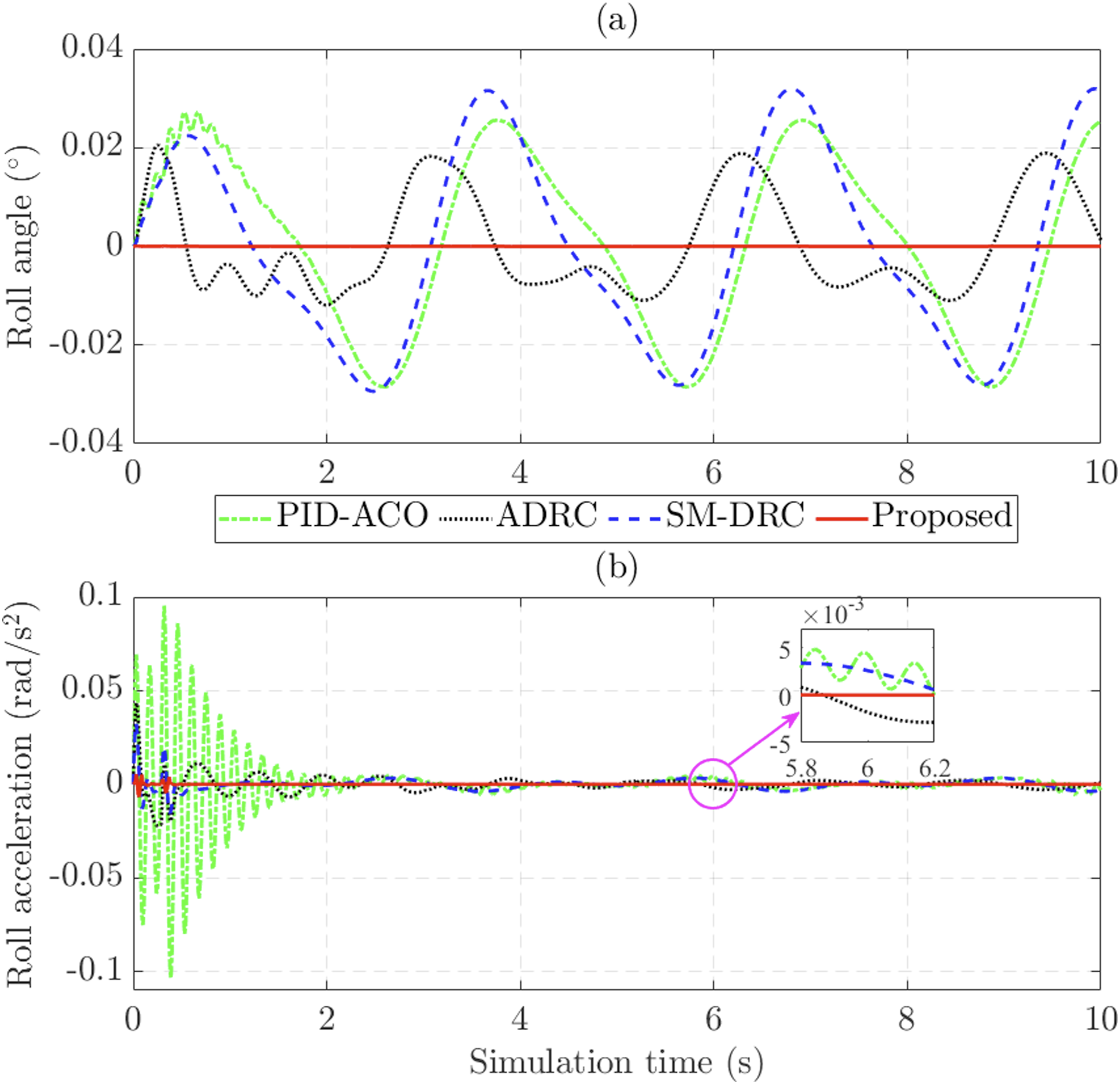
In this simulation scenario, the PID-ACO controller increases the roll acceleration to 0.103 rad/s2, which is significantly higher than that achieved by SM-DRC (0.033 rad/s2), ADRC (0.044 rad/s2), and the proposed control (0.007 rad/s2). The enlarged view in Figure 5(b) further shows that the response obtained by the proposed controller remains stable and smooth. In contrast, the signal generated by PID-ACO is highly sensitive to uncertainties and external disturbances.
Under the influence of adverse factors, including model nonlinearities, road disturbances, and lumped uncertainties, the PID-ACO controller exhibits poor suspension regulation performance, resulting in a pitch angle increasing to 0.023° and oscillating continuously over a wide range. Owing to their disturbance rejection capability, SM-DRC and ADRC significantly reduce the pitch angle to no more than 0.006° and 0.012°, respectively. In contrast, the proposed control strategy provides a substantial improvement in pitch stability by reducing the pitch angle to only 0.00002°, as shown in Figure 6(a). Pitch dynamics behaviors (sinusoidal wave road excitation). (a) Pitch angle; (b) pitch acceleration.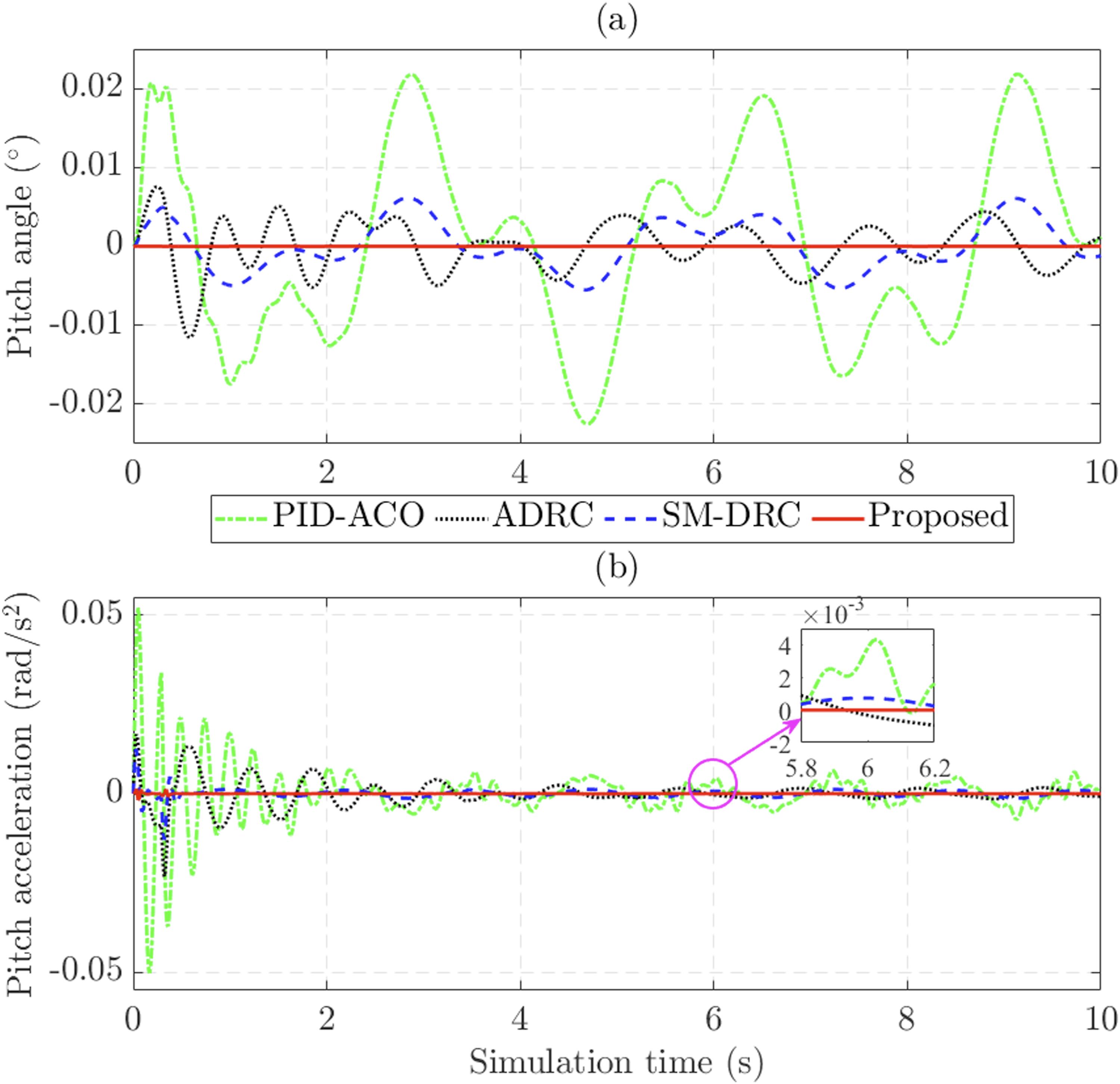
In this simulation case, the pitch acceleration also exhibits significant variation due to the strong influence of the lumped pitch uncertainty on the suspension system. The calculated results show that the maximum pitch acceleration reaches 0.052 rad/s2 for PID-ACO, 0.013 rad/s2 for SM-DRC, and 0.023 rad/s2 for ADRC, whereas it is reduced to only 0.002 rad/s2 under the proposed controller. The enlarged view in Figure 6(b) further confirms that the response obtained by the proposed method is significantly more stable than those of PID-ACO and ADRC.
Actuator performance is evaluated by the active forces generated by the hydraulic actuators. The simulation results in Figure 7 show that Fa11 and Fa21 exhibit greater variations than the other active forces. This is mainly because only one side of the vehicle is directly subjected to road excitation, requiring larger control efforts at the corresponding suspension corners. Actuator performance (sinusoidal wave road excitation). (a) Fa11; (b) Fa12; (c) Fa21; (d) Fa22.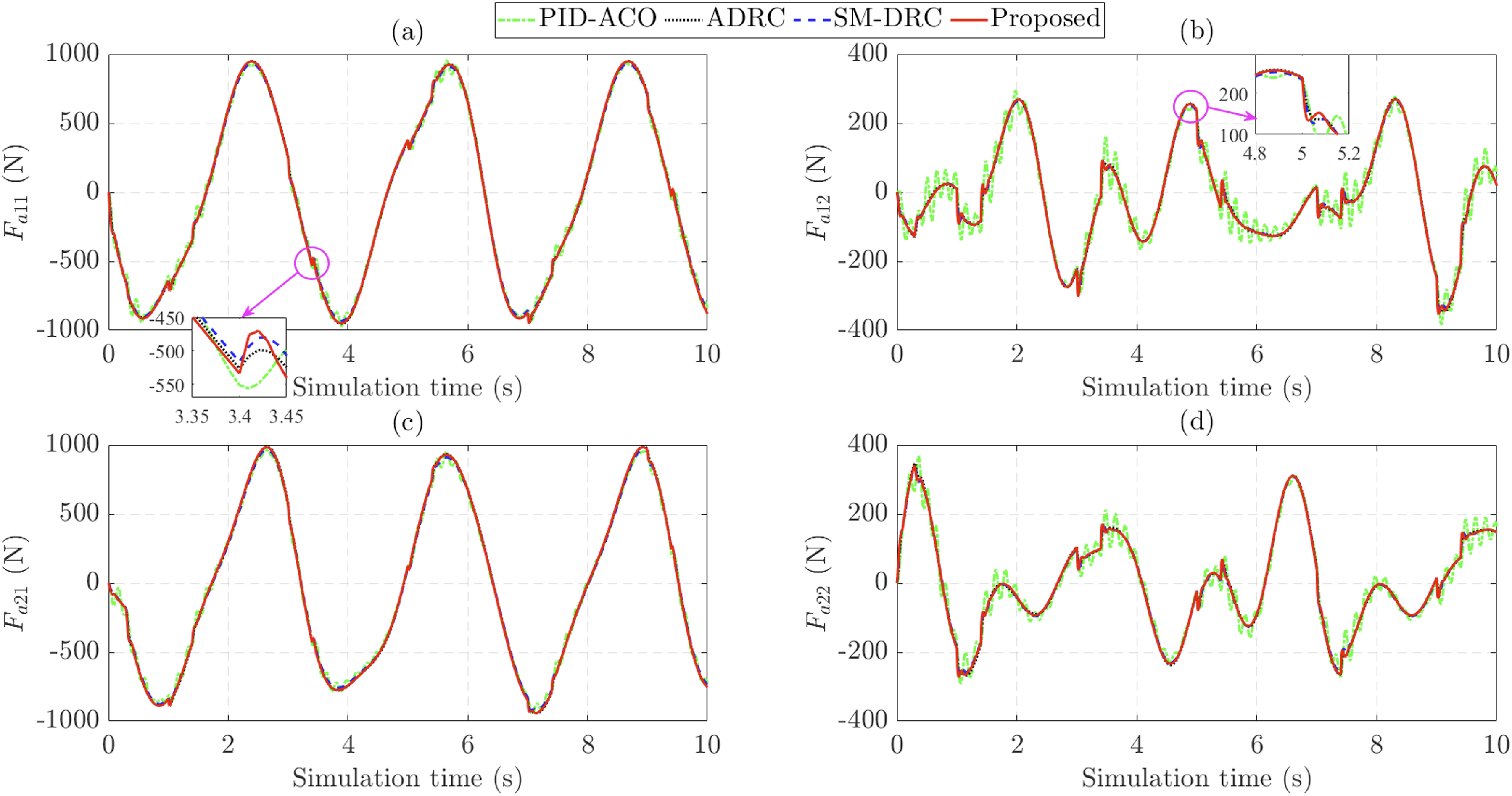
The enlarged view in Figure 7(a) shows that, at several time instants, the generated force exhibits slight fluctuations and small discontinuities. This behavior is mainly caused by the rectangular pulse characteristic of the lumped heave uncertainty, which introduces sudden disturbance changes into the hydraulic actuator response. However, these fluctuations do not have a noticeable negative effect on the vehicle’s ride comfort.
Simulation results (sinusoidal wave road excitation).
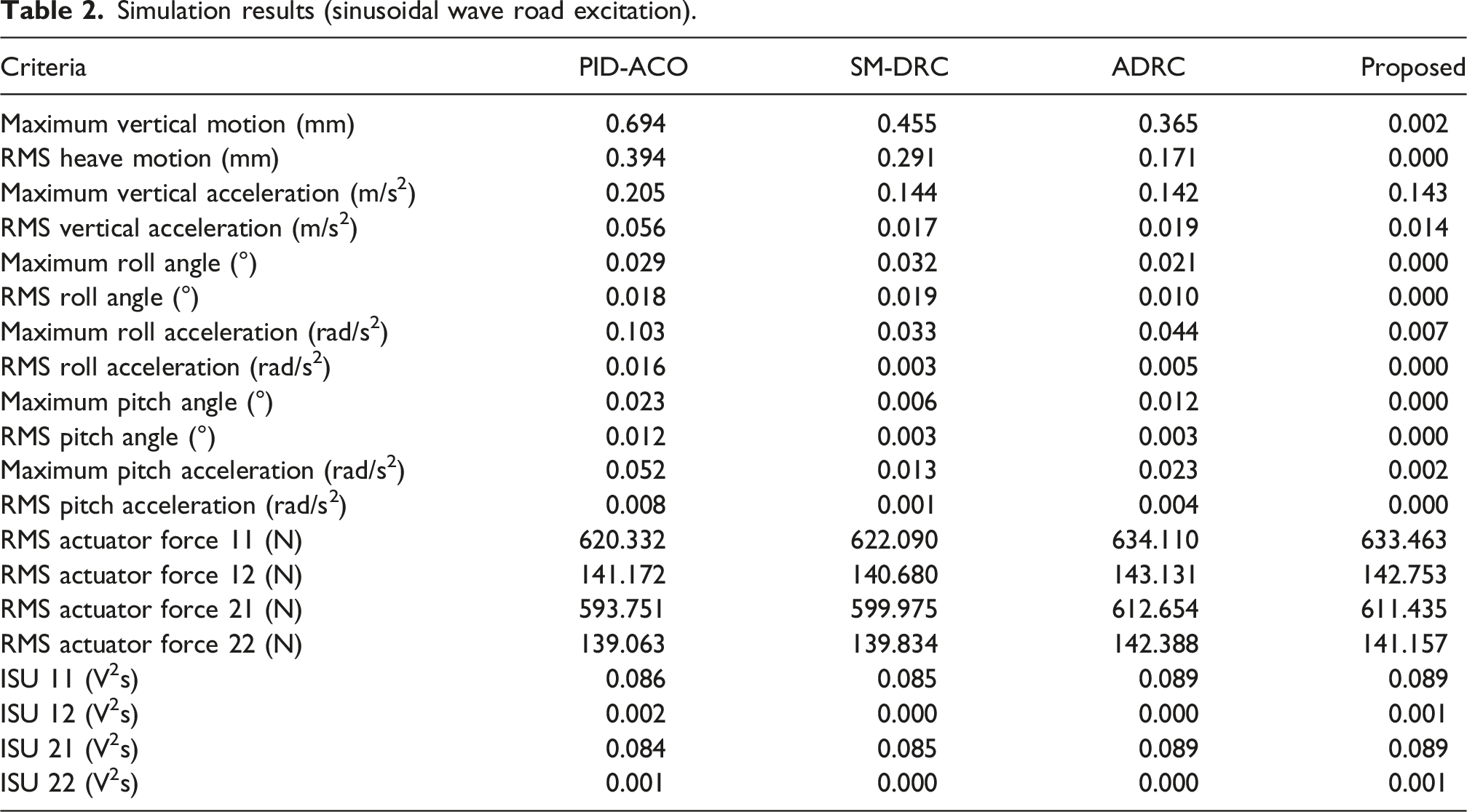
In this simulation scenario, the electrical energy consumption of all controllers remains relatively low. The integrated square control input (ISU), illustrated in Figure 8(a), shows only small differences among the compared methods, with specific values of 0.086 V2s for PID-ACO, 0.085 V2s for SM-DRC, 0.089 V2s for ADRC, and 0.089 V2s for the proposed control. Control inputs (sinusoidal wave road excitation). The simulation results for the first investigation scenario are summarized in Table 2. (a) u11; (b) u12; (c) u21; (d) u22.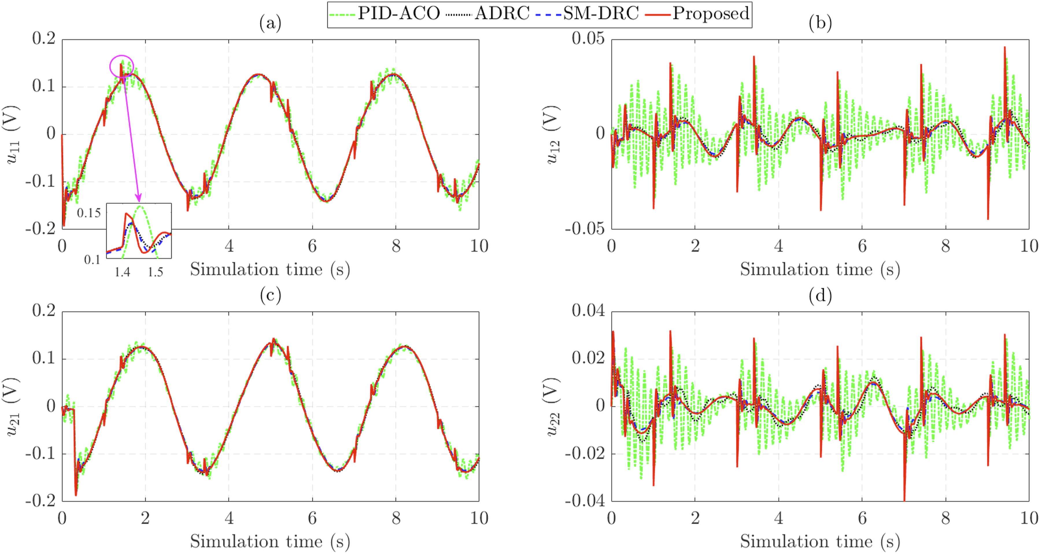
Overall, the proposed controller provides superior performance in improving ride comfort and roll and pitch stability, while maintaining energy consumption comparable to that of the other control methods. This demonstrates that the improvement in suspension performance is achieved without requiring additional control energy.
3.2. Performance under random road excitation
In the second simulation scenario, a white-noise road excitation, following the ISO 8608 D-class standard, is used as the road disturbance input. Lumped uncertainties are still accounted for throughout the simulation to evaluate the robustness of the proposed control strategy under more severe operating conditions.
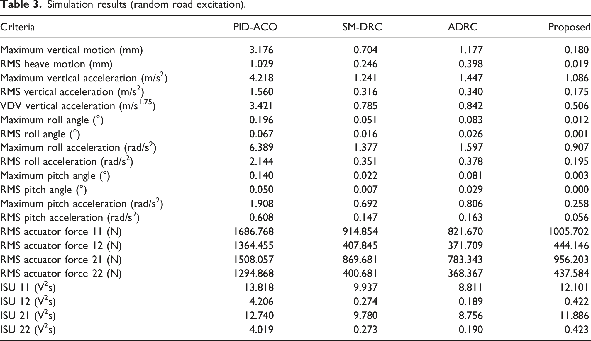
Under strong random road excitation, the heave dynamic behaviors exhibit significant variations. According to the simulation results shown in Figure 9(a), the sprung mass displacement increases to 3.176 mm when the suspension system is controlled by the PID-ACO method. The peak values are reduced to 0.704 mm, 1.177 mm, and 0.180 mm when PID-ACO is replaced by SM-DRC, ADRC, and the proposed control, respectively. In terms of RMS performance, the proposed controller achieves the lowest value of only 0.019 mm, which is significantly lower than those obtained by ADRC (0.398 mm), SM-DRC (0.246 mm), and PID-ACO (1.029 mm). Heave dynamics behaviors (random road excitation). (a) Vehicle body motion; (b) vehicle body acceleration.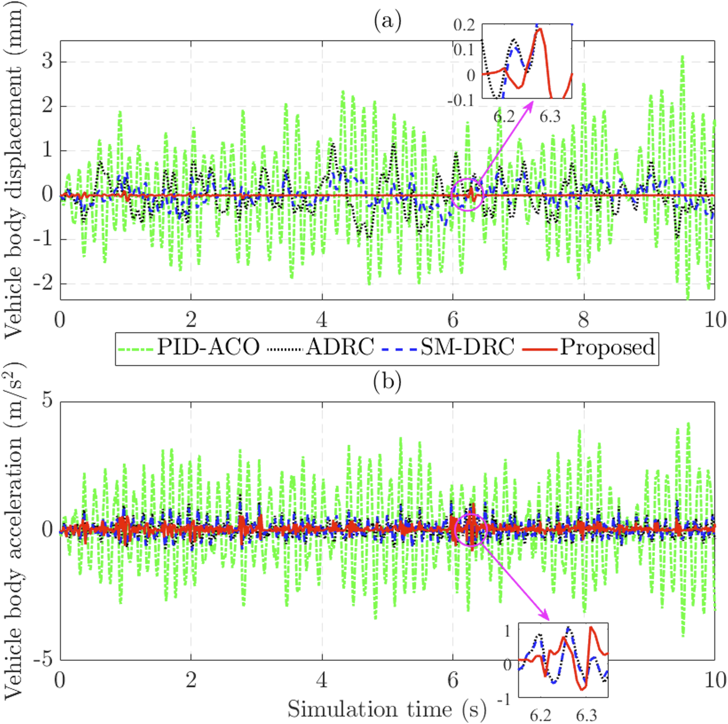
In this simulation scenario, the maximum vertical body acceleration increases to 4.218 m/s2 when PID-ACO controls the suspension system. Owing to their effective disturbance rejection capability, SM-DRC and ADRC reduce the peak acceleration to no more than 1.241 m/s2 and 1.447 m/s2, respectively. The proposed control strategy achieves a significant improvement, further reducing the vehicle body acceleration to 1.086 m/s2. According to the VDV criterion, the acceleration value obtained by the proposed controller is only 0.506 m/s1.75, which is significantly lower than those achieved by ADRC (0.842 m/s1.75), SM-DRC (0.785 m/s1.75), and PID-ACO (3.421 m/s1.75). These results confirm that the proposed control strategy, combined with the optimal force allocation method, significantly improves ride comfort even when the suspension system is strongly affected by adverse factors, including road disturbances, model nonlinearities, and lumped uncertainties.
To provide a more standardized ride comfort assessment, the frequency-weighted RMS acceleration defined in ISO 2631 was also evaluated using the vertical vibration weighting filter (W k ). The weighted RMS accelerations were 1.6111 m/s2, 0.3039 m/s2, 0.2795 m/s2, and 0.0978 m/s2 for the PID-ACO, ADRC, SM-DRC, and proposed AFxTSMC–ADRC controllers, respectively. Compared with PID-ACO, ADRC, and SM-DRC, the proposed controller reduced the weighted RMS acceleration by 93.9%, 67.8%, and 65.0%, respectively. These results further demonstrate that the proposed control strategy effectively suppresses vibration components within the frequency range most relevant to human ride comfort, thereby providing superior comfort performance under random road excitation.
The simulation results in Figure 10(a) illustrate the variation of the roll angle. A closer observation shows that the roll angle increases significantly to 0.196° when the suspension system is controlled by the conventional PID-ACO method. In contrast, disturbance-rejection-based controllers reduce the influence of adverse factors, resulting in lower roll angles of 0.051° for SM-DRC and 0.083° for ADRC. The proposed control strategy achieves a remarkable improvement, limiting the roll angle to 0.012° or less. Roll dynamics behaviors (random road excitation). (a) Roll angle; (b) roll acceleration.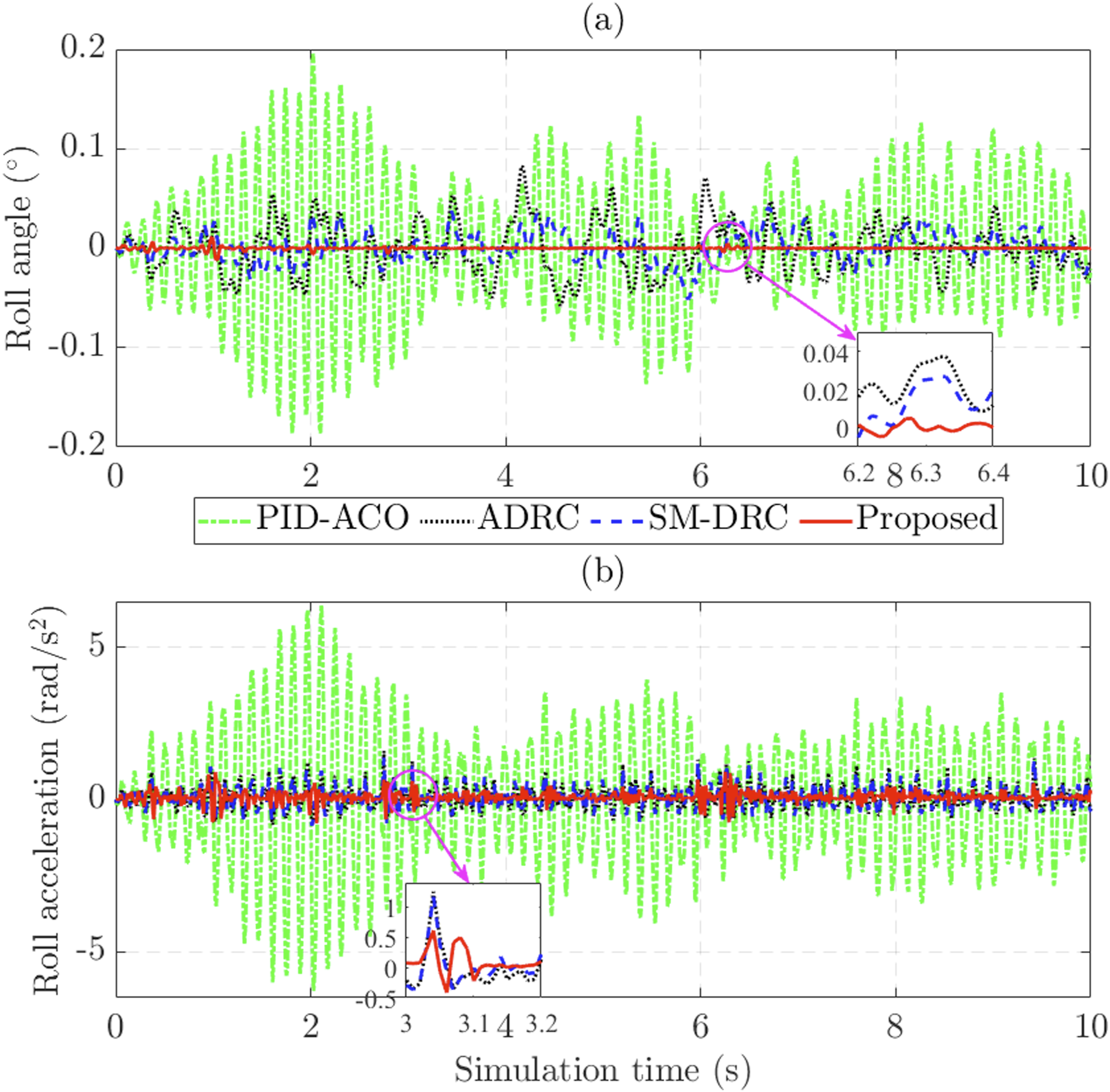
Roll stability is further evaluated by examining variations in roll acceleration. The simulation results in Figure 10(b) indicate that the maximum and RMS roll accelerations obtained by PID-ACO are 6.389 rad/s2 and 2.144 rad/s2, respectively. For SM-DRC, these values are reduced to 1.377 rad/s2 and 0.351 rad/s2, while ADRC produces 1.597 rad/s2 and 0.378 rad/s2. Owing to its superior control performance, the proposed controller significantly improves roll stability by reducing the peak roll acceleration to 0.907 rad/s2 and the RMS value to 0.195 rad/s2. Overall, even when the system is strongly affected by lumped roll uncertainty, the proposed control strategy maintains roll stability effectively.
Pitch instability is clearly observed when the suspension system is controlled by conventional methods such as PID-ACO. Even with ADRC’s disturbance rejection capability, the pitch angle still varies over a relatively wide range. The simulation results in Figure 11(a) show that the proposed control strategy significantly suppresses pitch dynamic behaviors, limiting the pitch angle to no more than 0.003°, which is substantially lower than those obtained by ADRC (0.081°), SM-DRC (0.022°), and PID-ACO (0.140°). Pitch dynamics behaviors (random road excitation). (a) Pitch angle; (b) pitch acceleration.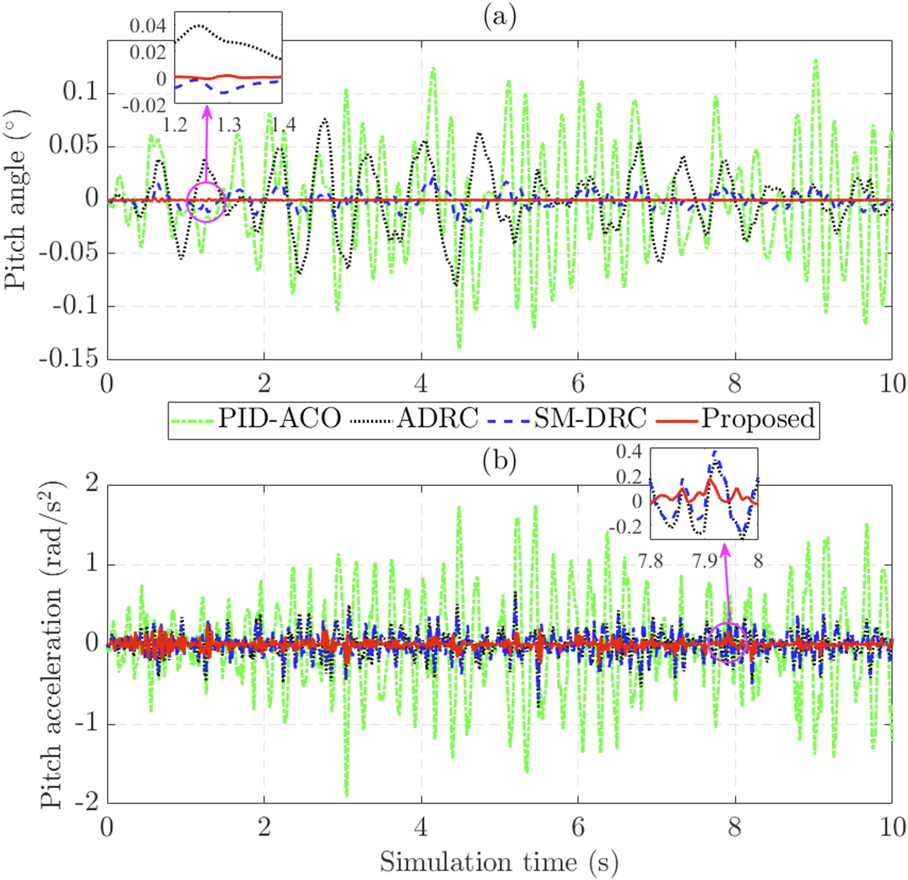
In this simulation scenario, the pitch acceleration also exhibits significant variation, as shown in Figure 11(b). Specifically, the RMS value of pitch acceleration is 0.608 rad/s2 for PID-ACO, 0.147 rad/s2 for SM-DRC, and 0.163 rad/s2 for ADRC, whereas the proposed controller yields only 0.056 rad/s2. These results confirm that the proposed control strategy effectively improves pitch stability even when the suspension system is strongly affected by lumped pitch uncertainty.
The calculation results in Figure 12 show that the proposed controller generates slightly larger active forces than ADRC and SM-DRC, which are sufficient to effectively suppress the vibrations transmitted from the road surface to the vehicle body. In contrast, the active forces produced by PID-ACO are excessively large, while the corresponding improvement in suspension performance remains limited. This indicates that the proposed control strategy achieves a more reasonable balance between control effort and vibration suppression performance. Although the actuator output is only moderately higher than that of ADRC and SM-DRC, the significant improvements in ride comfort and roll and pitch stability clearly demonstrate the effectiveness of the proposed method under severe random road excitation conditions. Actuator performance (random wave road excitation). (a) Fa11; (b) Fa12; (c) Fa21; (d) Fa22.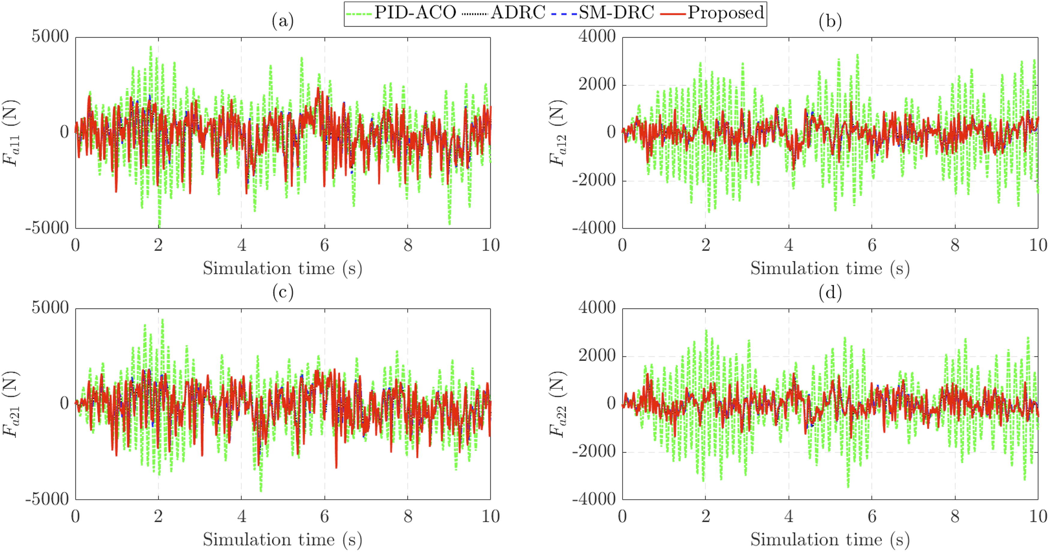
Even under severe road excitation, the controller requires only moderate energy to generate the necessary active forces. The results in Figure 13(a) show that the ISU of the proposed control is 12.101 V2s, which is slightly higher than that of SM-DRC (9.937 V2s) and lower than that of PID-ACO (13.818 V2s). Overall, the performance improvement achieved by the proposed controller is significant, providing substantial enhancements in ride comfort and roll and pitch stability while maintaining a relatively low level of electrical energy consumption. This demonstrates that the proposed strategy can effectively balance suspension performance and control energy requirements under strong random road disturbances. Control inputs (random wave road excitation). (a) u11; (b) u12; (c) u21; (d) u22.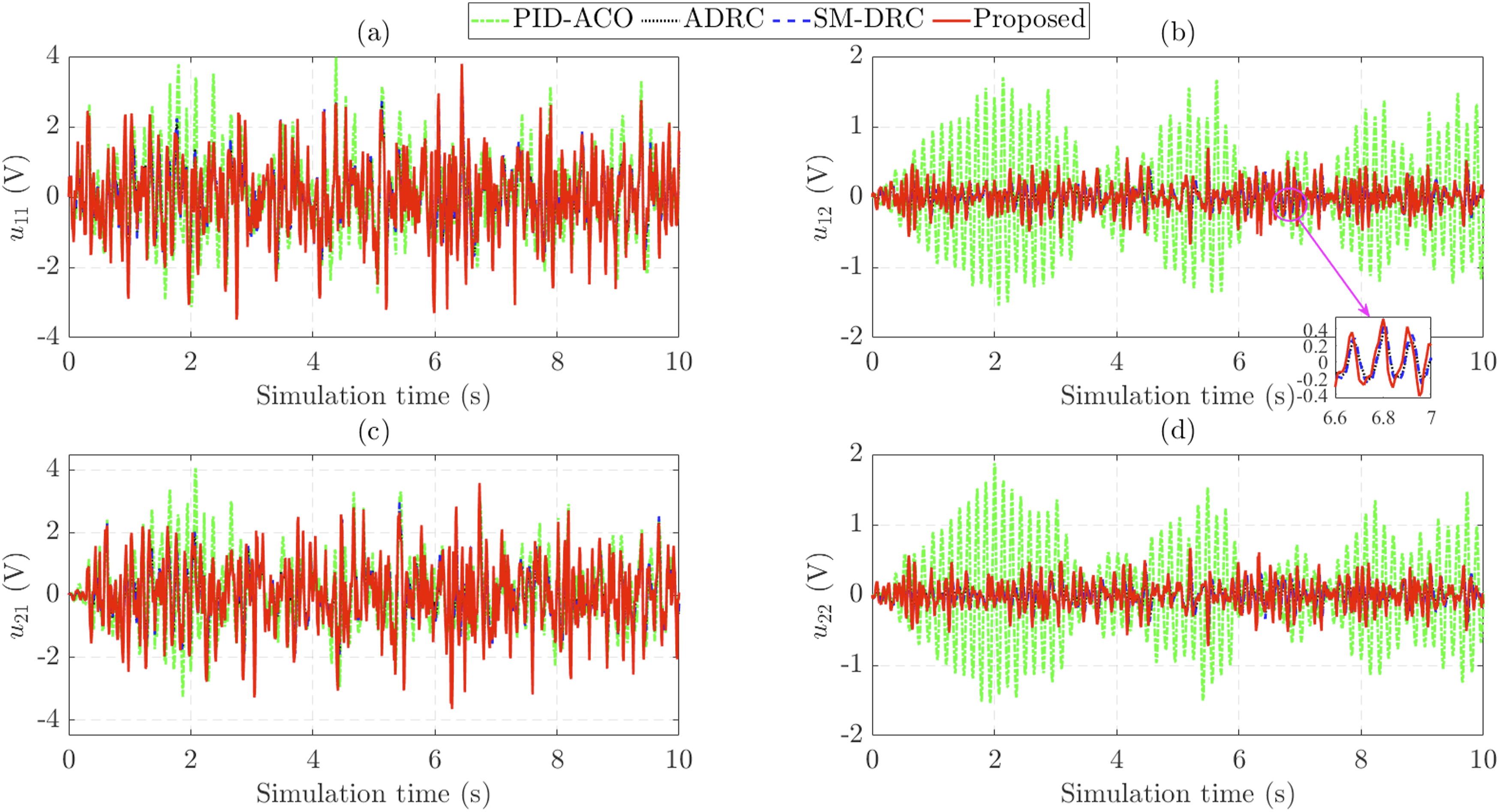
The ISU metric was used to quantify the control effort required for each suspension control strategy. The simulation results indicate that the proposed controller achieves noticeable improvements in ride comfort and vehicle body motion suppression while maintaining a reasonable level of control effort. This suggests that performance enhancement is not solely due to excessive actuator activity, but rather to a more effective use of the available control input. Nevertheless, the balance between vibration attenuation and energy consumption remains an important consideration in active suspension design and warrants further attention in subsequent investigations.
Simulation results (random road excitation).
3.3. Discussion
The simulation results obtained under both sinusoidal and random road excitations clearly demonstrate the effectiveness of the proposed control strategy for the full-vehicle active suspension system with hydraulic actuators. Compared with PID-ACO, ADRC, and SM-DRC, the proposed method provides significant improvements in ride comfort, heave suppression, and roll–pitch stability, while maintaining a reasonable level of actuator effort and electrical energy consumption.
Under sinusoidal road excitation, the proposed controller almost eliminates the influence of lumped heave uncertainty and significantly reduces sprung mass displacement and vertical body acceleration. Similar improvements are observed in roll and pitch dynamics, where both angular displacement and angular acceleration are substantially suppressed. These results indicate that integrating the fixed-time sliding mode structure with active disturbance rejection improves disturbance attenuation and enhances transient response.
Under the more severe random road excitation condition based on the ISO 8608 D-class profile, the superiority of the proposed method becomes more evident. Even in the presence of strong road disturbances, model nonlinearities, and lumped uncertainties, the controller maintains low vehicle body displacement, reduced acceleration responses, and stable roll and pitch motions. This confirms the robustness of the proposed strategy and its suitability for practical suspension applications where uncertainties cannot be neglected.
Another important advantage of the proposed approach is the use of the optimal force allocation strategy that distributes the generalized control forces among the four hydraulic actuators according to the minimum-norm criterion. This helps avoid unnecessary actuator overload and improves the coordination of suspension forces. In addition, the cascade PID structure in the hydraulic actuator subsystem enhances force-tracking accuracy. It ensures that the actuator can effectively realize the desired control force generated by the outer-loop controller.
Although the proposed controller generates slightly larger active forces than ADRC and SM-DRC in some operating conditions, the corresponding improvement in suspension performance is significantly greater. More importantly, the electrical energy consumption remains at an acceptable level and is still lower than that of PID-ACO under strong random road excitation. This demonstrates that performance enhancement is achieved without excessive control energy.
However, several limitations remain in this study. First, the validation is currently based only on numerical simulation results, while experimental verification on a real hydraulic suspension test rig has not yet been conducted. Second, the hydraulic actuator model is simplified by neglecting practical factors such as valve dead zone, friction effects, fluid temperature variation, and parameter aging, which may influence real-world performance. Third, road excitation is applied primarily to one side of the vehicle to emphasize asymmetric suspension behavior. At the same time, more complex driving conditions, such as steering maneuvers, braking, and cornering, have not been considered.
From an implementation perspective, the proposed AFxTSMC–ADRC algorithm mainly consists of algebraic operations, observer updates, and adaptive-law calculations, making it suitable for real-time execution on modern automotive embedded controllers. Nevertheless, practical deployment may be affected by sensor noise, sampling delays, quantization effects, and actuator nonlinearities such as dead zones and saturation. Although these factors were not explicitly considered in the present study, the observer-based structure and boundary-layer design are expected to provide some robustness against measurement imperfections. A more comprehensive investigation of real-time implementation issues will be considered in following study.
Future work will focus on hardware-in-the-loop experiments and real-vehicle validation to further verify the practical applicability of the proposed method. In addition, more comprehensive actuator nonlinearities and multi-objective optimization strategies for ride comfort, handling stability, and energy efficiency will be considered to improve suspension control performance further.
4. Conclusion
This article proposed a robust nonlinear control strategy for a full-vehicle active suspension system with hydraulic actuators to improve ride comfort and enhance vehicle body stability under road disturbances, model nonlinearities, and lumped uncertainties. A full-vehicle model was established that explicitly accounts for suspension nonlinearities and hydraulic actuator dynamics.
An optimal active force allocation method based on the Moore–Penrose pseudo-inverse was introduced to distribute the generalized control forces among the four actuators while ensuring heave, roll, and pitch stability. In addition, the cascade control structure combining AFxTSMC, ADRC, and the inner-loop PID controller was developed to improve disturbance rejection and actuator force-tracking performance.
Simulation results under sinusoidal and random road excitations confirmed that the proposed method significantly improves ride comfort, suppresses heave, roll, and pitch vibrations, and maintains good vehicle stability with reasonable control effort and energy consumption. Future work will focus on experimental validation using a hydraulic suspension test rig and on the inclusion of additional practical actuator nonlinearities to further improve real-world applicability.
Footnotes
Acknowledgments
The author acknowledges the use of ChatGPT and Grammarly applications for grammar checking and language polishing to enhance the clarity and readability of the manuscript.
Funding
This study received no specific grant from any funding agency in the public, commercial, or not-for-profit sectors.
Declaration of conflicting interests
The author declared no potential conflicts of interest with respect to the research, authorship, and/or publication of this article.
Data Availability Statement
The data that support the findings of this study are included in the article.