
Abstract
This paper proposes an inerter negative-stiffness tuned mass damper (INTMD), which aims to enhance the vibration control performance of structures under harmonic, pedestrian-induced and wind-induced excitations. The motion equation of a single degree of freedom with INTMD is derived, and the expressions of the dynamic amplification factor and the closed-form solution of the stability condition for the SDOF-INTMD system are obtained. The closed-form optimal parameters for the INTMD under harmonic excitations are derived based on the H∞ criterion. Parameter analyses are performed on the INTMD system. The results demonstrated that the vibration reduction effect is highly sensitive to the stiffness and inerter. Additionally, the inerter stiffness and negative stiffness complement each other functionally. Finally, the vibration control performance of the optimally configured INTMD is quantitatively evaluated under harmonic and wind-induced excitations. The results show that the INTMD achieves significantly better vibration control effectiveness than both the conventional TMD and the Maxwell TMD for the same mass ratio.
Keywords
1. Introduction
In the field of vibration control, the use of tuned mass dampers (TMDs) has always been a popular research topic. With advancements in technology and improvements in construction requirements, there is an urgent need to explore new vibration control mechanisms to achieve effective reductions in structural vibration responses. Among these novel methods, the technical scheme of integrating inerter elements and negative stiffness elements into Tuned Mass Dampers (TMDs) has shown significant application prospects.
The inerter is a mechanical component related to acceleration, and its essence is an inertial force amplification device (Ma et al., 2021). In 2002, Smith (2002) formally named this “inerter” by leveraging the force-current analogy (analogous to capacitance) between mechanical and electrical networks and applying for a patent for it. Chen et al. (2014) studied the influence of inerters on the natural frequency of vibration systems. Through algebraic derivation and sensitivity analysis of the natural frequencies of single-degree-of-freedom (SDOF) systems and multi degree of freedom (MDOF) systems, they proved that inerters can effectively reduce the natural frequency of the system. In the civil engineering field, researchers are committed to developing passive control systems based on inerters, which are used to reduce vibrations caused by human-induced loads, vehicle loads, wind loads and seismic loads (De Angelis et al., 2021).
In 2014, Marian and Giaralis (2014) proposed the Tuned Mass Damper Inerter (TMDI), which utilizes the “mass amplification effect” of the inerter to supplement the mass effect of the mass block, thus exhibiting superior performance compared with classical TMDs. In 2015, Ruiz et al. (2018) introduced the concept of the Inerter-based Dynamic Vibration Absorber (IDVA), which replaces the damper element in the TMD with different configurations of inerter masses, dampers, and springs connected in series or parallel. Pietrosanti et al. (2017) explored the optimal design and performance of TMDIs in vibration reduction. Based on the white noise excitation model, three different optimal design methods were adopted for TMDI, namely, the displacement minimization method, the acceleration minimization method, and the method of maximizing the ratio of energy dissipated by the secondary system to the total input energy. The results show that for the same mass ratio, the TMDI is more effective than the TMD. Zhou et al. (2022) conducted an H∞ study on the TMDI for an SDOF structure under harmonic excitation with stiffness uncertainty. Dai et al. (2019) investigated the effect of the position of an inerter on the control performance of the Tuned Mass Damper Inerter (TMDI) for mitigating wind-induced vibrations in flexible structures. Bai et al. (2025) proposed a TMDI-TIBD enhanced by a tuned inerter damper, which achieves superior vibration mitigation performance, stronger robustness, and lower tuning mass requirements compared to conventional TMD and TMDI through triple tuning and inerter mass amplification effects; Zeng et al. (2026) targeting low-frequency vertical-bending vortex-induced vibrations in long-span bridges, developed a rapid design method for the TMDI inertance-to-mass ratio and revealed that increasing the spring index effectively lowers the lower-bound frequency and the required inertance-to-mass ratio, thereby enhancing vibration mitigation performance. De Domenico et al. (2020) utilized the characteristics of the Tuned Mass Damper Inerter (TMDI) to improve the seismic performance of substructure systems and further optimized and designed the application of TMDIs in high-rise buildings.
Negative stiffness mechanical devices can significantly improve vibration isolation performance by counteracting the stiffness of spring suspensions, with particularly prominent effects in the low-frequency range (Zhao et al.,2025, 2026). In 1957, Molyneaux (1957) first proposed the concept of negative stiffness and investigated its characteristics. Platus (1992) utilized the negative stiffness mechanism to eliminate the stiffness of the spring suspension. The reduction in stiffness amplifies the inherent damping of the system, thereby significantly enhancing the performance of the new vibration isolation system. As early as the late 1990s, Alabuzhev (1989) proposed a vibration isolation system with negative stiffness and introduced its principles and practical applications. Gao et al. (2026) proposed a new vibration reduction system formed by paralleling positive stiffness elements with negative stiffness elements. Research has shown that this system has a relatively significant vibration reduction effect. Since then, negative stiffness technology has been widely used in the field of civil engineering.
On the basis of inerter, negative stiffness, and mass tuning technology, Wang et al. (2022) conducted an optimization design via H∞ theory. Gao et al. (2022) subsequently proposed a Tuned Mass Damper Inerter with negative stiffness element (TMDI-NSD), derived its dynamic amplification factor, optimized its parameters based on the H∞ norm, H2 norm, and stability maximization criterion, and compared its performance advantages with those of the Tuned Inerter Damper (TID) and Tuned Inerter Damper with Negative Stiffness Device (TIDNSD). Tai et al. (2025) conducted an in-depth study on the vibration isolation control performance of the Tuned Mass-Negative Stiffness Inerter Damper (TMNID), derived the absolute transmissibility of the SDOF TMNID, obtained the analytical solutions for the optimal parameters of the TMNID based on H∞ norm optimization and H2 norm optimization, and performed a sensitivity analysis. Based on the research findings of Tai et al., this paper proposes a novel inerter negative stiffness tuned mass damper (INTMD), which has excellent application potential in vibration reduction.
The structure of this paper is as follows: Section 2 derives the motion equation, dynamic amplification factor, and stability condition of the INTMD system. Section 3 deduces the optimal parameter expressions based on the H∞ norms. Section 4 analyses the parameter variation laws. The vibration reduction performance of the INTMD is evaluated in Section 5. Finally, Section 6 presents the concluding remarks.
2. Mathematical model of SDOF-INTMD
2.1. Dynamic amplification factor
The mechanical model of an SDOF system with an Inerter Negative Stiffness Tuned Mass Damper (INTMD) is shown in Figure 1. The red dashed box encloses the vibration absorber, namely, the INTMD. m1, c1 and k1 denote the mass, damping, and stiffness of the controlled structure, respectively. m
b
, b and c
b
are the additional mass, inertance, and damping of the INTMD, respectively. kb1 and kb2 denote the two positive stiffnesses of the INTMD, and k
ns
is the negative stiffness. x1 and x
b
are the displacement of the controlled structure relative to the ground and the displacement of the INTMD relative to the controlled structure, respectively. On the basis of Lagrange’s equations, the kinetic energy T, potential energy V, and damping energy dissipation D of this coupled system can be obtained as shown in equation (1). The mechanical model of SDOF-INTMD.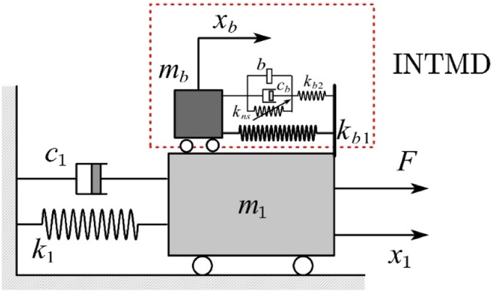
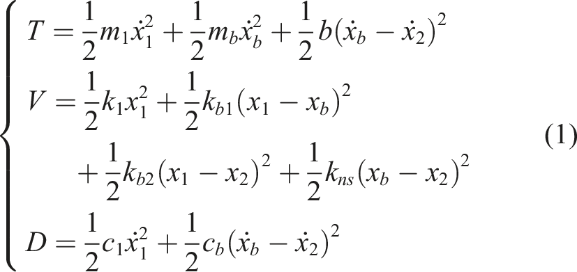
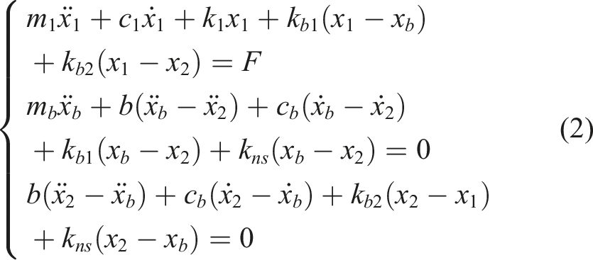
From equation (1), the motion equation for this coupled system can be derived as shown in equation (2).
For the controlled structure, the applied harmonic excitation force can be expressed as shown in equaiton (3), where F0 is the force amplitude, i denotes the imaginary number, ω and t are the excitation frequency and time, respectively.

The displacements, velocities, and accelerations of the controlled structure, inerter, and mass block are shown in equation (4), where X1, X2 and X
b
are the amplitudes of x1, x2 and x
b
, respectively.

Substituting equations (3) and (4) into equation (2) and eliminating e
iωt
from both sides of the equations yields equation (5).
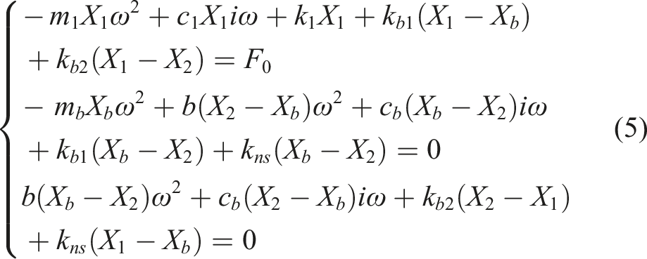
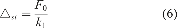
The static displacement of the controlled structure under the force amplitude F0 is shown in equation (6).
Dividing both sides of equation (5) by
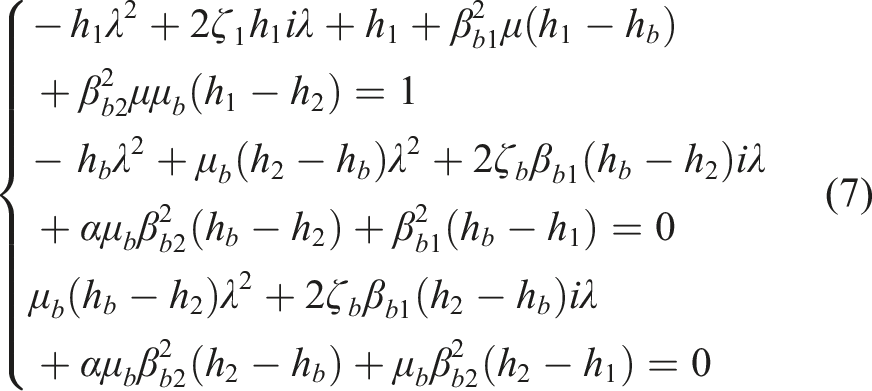
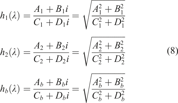
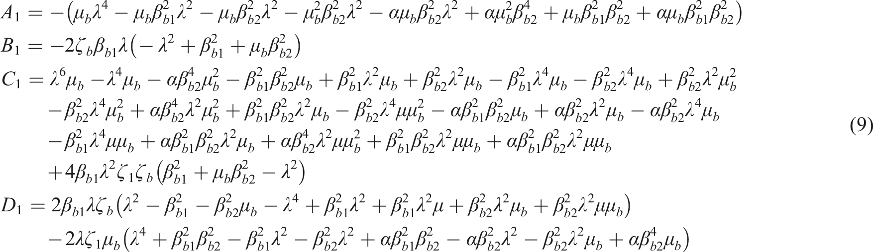
From equation (7), the dynamic amplification factors of the controlled structure, inerter, and mass block can be derived as h1(λ), h2(λ) and hb(λ), respectively, with the details shown in equation (8).
2.2. Stability conditions
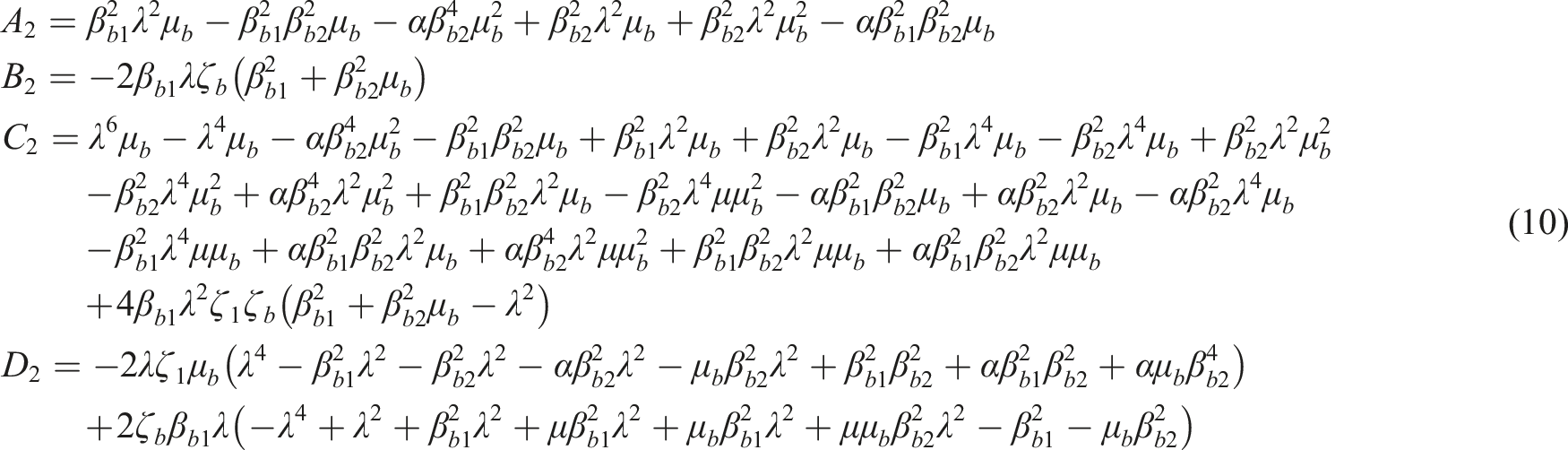
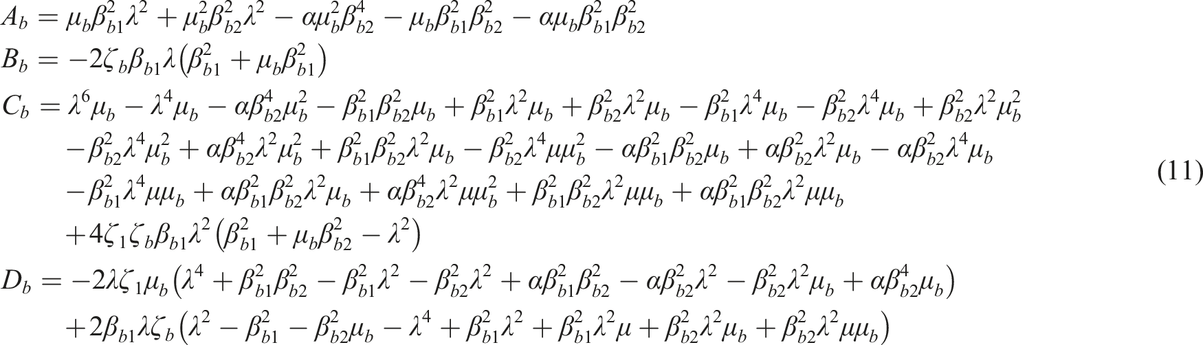
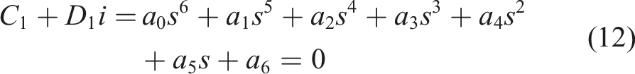
The integration of a negative stiffness element into the INTMD can give rise to the instability phenomenon of the controlled system. It is necessary to determine the stability conditions of the INTMD system before conducting parameter optimization and numerical analysis. To ensure the stable operation of the INTMD system and clarify the parameter range of the negative stiffness element, this paper introduces the Routh–Hurwitz criterion (Hurwitz, 1963) for quantitative analysis. s = iλ is substituted into the characteristic equation of the SDOF-INTMD system to obtain the expression shown in equation (12),
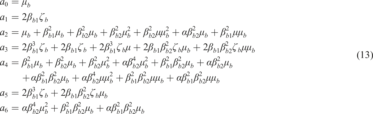
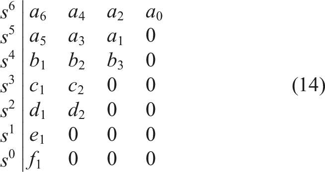
This derivation is based on the Routh criterion, and its Routh array is shown in equation (14).
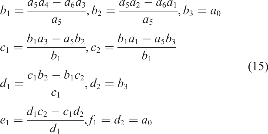
Based on the condition that each coefficient needs to be satisfied in the Routh–Hurwitz stability criterion, the following inequalities can be obtained:
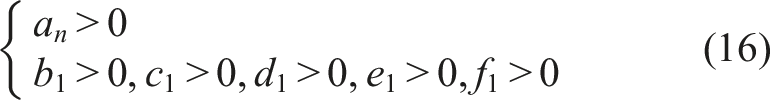
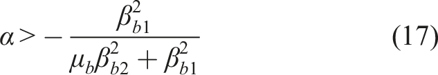
According to inequality (16), the limiting condition of the negative stiffness ratio α can be obtained, as shown in equation (17).
3. Parameter optimization of INTMD
The parameter optimization of vibration control systems can be categorized into two types: numerical optimization and analytical optimization. Among them, analytical optimization is applicable to solving the optimal parameters of linear systems under harmonic excitation and stationary excitation, and it can derive universal closed-form analytical solutions. In contrast, numerical optimization is more suitable for addressing parameter optimization problems in complex nonlinear systems or under non-stationary random excitation. In this paper, H∞ optimization adopts the analytical optimization method.
The extended fixed-point theory (Den Hartog, 1985), which is a combination of the classical fixed-point theory and the pole method, was first proposed by Den Hartog. In this section, extended fixed-point theory is used to obtain the optimal tuning frequency ratio, the optimal mass ratio, and the optimal negative stiffness coefficient. In addition, the optimal damping ratio is obtained via Krenk’s theory (Steen et al., 2016). The damping ratio ζ1 of the controlled structure is set to 0, and different dynamic amplification factor curves can be obtained by varying ζ
b
, as shown in Figure 2, where μ = 0.1, μ
b
= 0.05, βb1 = 0.8, βb2 = 1.2, α = −0.2 and ζ
b
values of 0, 0.05, 0.1, 0.15 and 0.2 are examined. Effect of the INTMD damping ratio on the dynamic amplification factor of the controlled structure.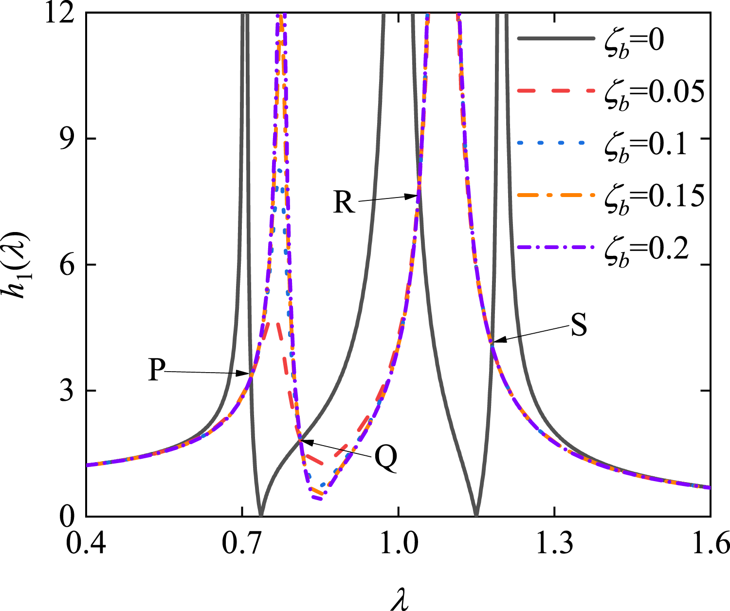
Analysis of the above different values of ζ b reveals that the dynamic amplification factor curves always pass through four fixed points, that is, P, Q, R and S, indicating that the positions of these four points are independent of the damping ratio ζ b of the INTMD.
3.1. Optimal solutions for βb1, βb2, μb and α
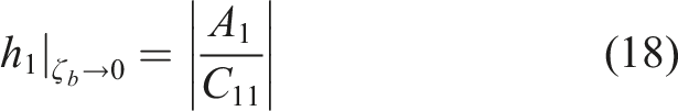
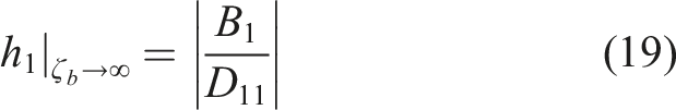
Since the damping ratio ζ
b
of the Inerter Tuned Mass Damper (INTMD) exerts no significant effect on the dynamic amplification factor at the fixed point of the system, ζ
b
→0 and ζ
b
→∞ are substituted into the dynamic amplification factor h1(λ) of the controlled structure. Thus, h1(λ) of the controlled structure is shown in equations (18) and (19).
At the fixed point, equating equation (18) to equation (19) yields equation (20).
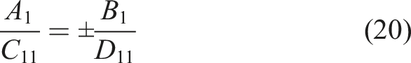
The adoption of the positive sign on the right-hand side of equation (20) could lead to the condition of λ = 0. In contrast, the employment of the negative sign gives rise to the following result:

Moreover, if the amplitude of the fixed-point displacement is denoted as h, that is, h1│ζb→∞ =

By applying Vieta’s theory to equations (21) and (23), two sets of equations can be obtained, as shown in equations (25) and (26), respectively.
By equating the corresponding equations in equation (25) and equation (26), equation (27) can be obtained.
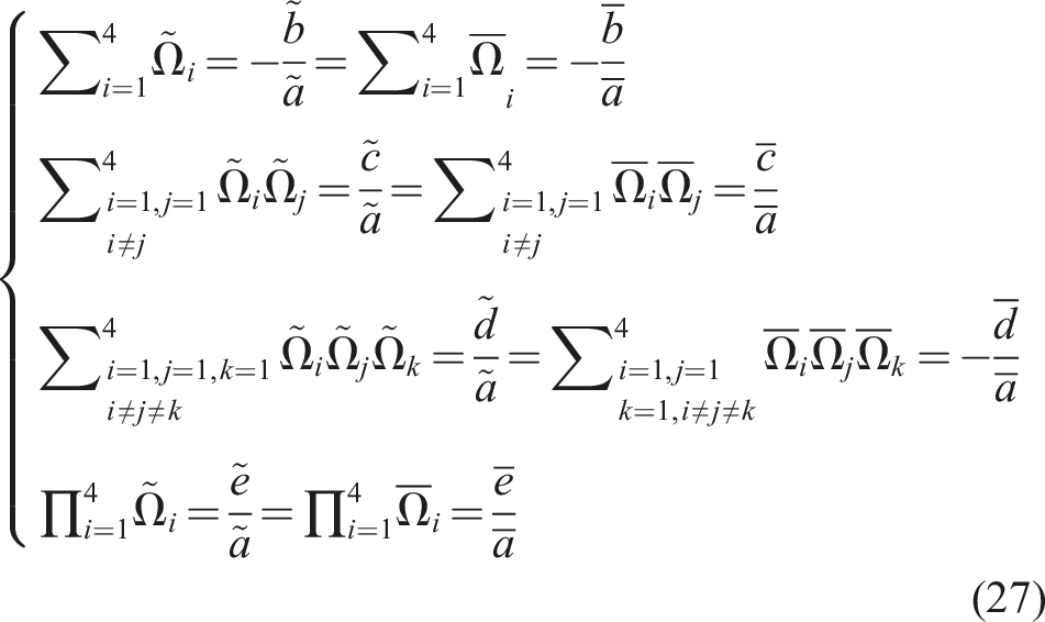
Rearranging equation (27) yields equation (28).
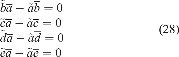
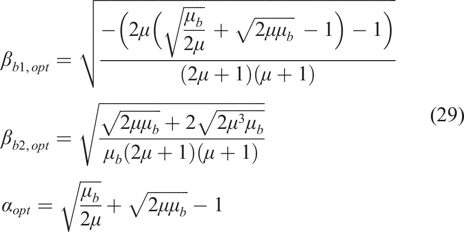
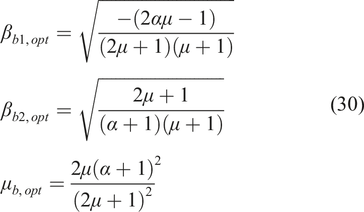
Solving equation (28) yields the analytical solutions for the optimal parameters under the following two scenarios: (a) Given the conditions of μ and μ
b
, the optimal parameters βb1,opt, βb2,opt and α
opt
are expressed in equation (29). (b) Given the conditions of μ and α, the optimal parameters βb1,opt, βb2,opt and μb,opt are expressed as shown in equation (30).
3.2. Optimal solutions for the damping ratio of the INTMD
The optimal damping ratio for INTMD can be determined by adjusting the maximum dynamic amplification factor to the same level as the fixed points. Figure 3 shows the constant frequencies of the INTMD, that is, Invariant frequencies 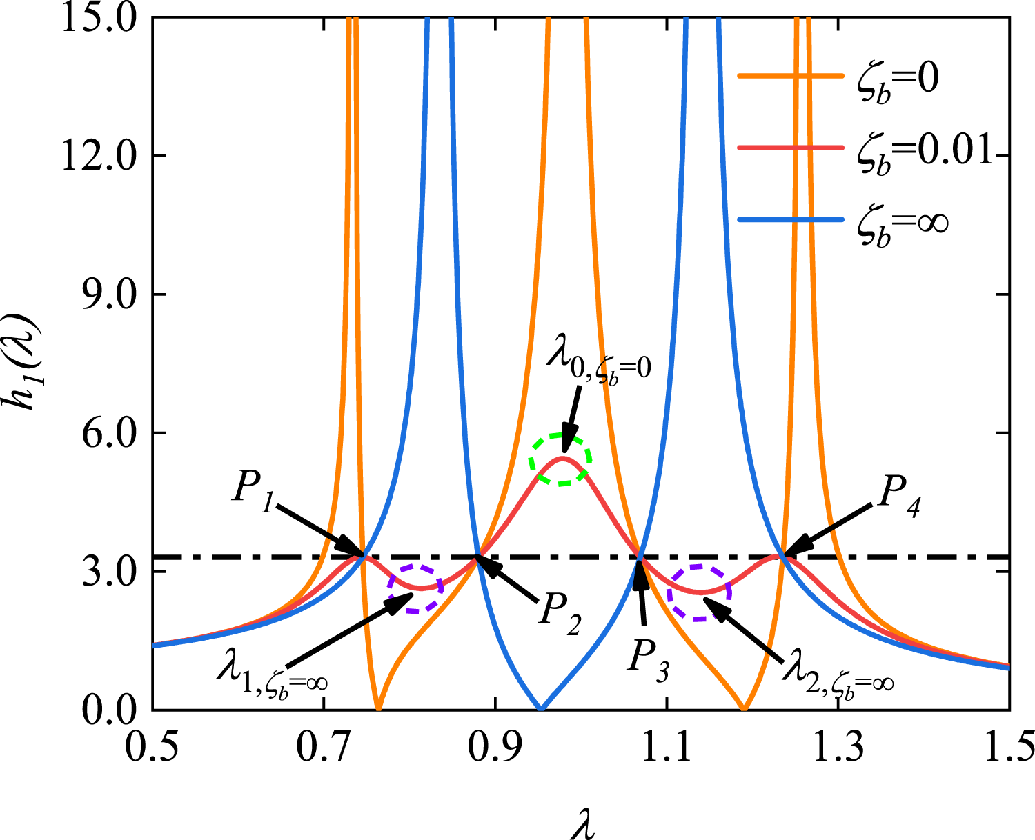
The invariant frequencies λ1,2,ζb→∞ can be obtained by solving equation (31).

Note that equation (31) is derived from the denominator of equation (19). Therefore, when ζ
b
→∞, the invariant frequencies are given by:
By substituting the optimal parameters βb1,opt, βb2,opt, α
opt
,
Figure 4 shows the optimized dynamic amplification factors. The curves of the optimal dynamic amplification factor for different mass ratios are shown in Figure 4(a), where μ
b
= 0.05 and μ ranges from 0.03 to 0.1. The results show that the curves have three approximately equal peaks under different mass ratios, which indicates that the INTMD under optimal working conditions. The dynamic amplification factor curves of the controlled structure for different damping ratios ζ1 are shown in Figure 4(b), where μ = 0.1, μ
b
= 0.05 and ζ1 ranges from 0 to 0.02. The peak value of the dynamic amplification factor curve is inversely proportional to ζ1. As ζ1 increases, only the peak values on both sides decrease without any sudden peak changes, indicating that the above optimization results are also applicable to the damped system. Dynamic amplification factor of the optimal INTMD system for different parameters: (a) mass ratio μ, (b) structural damping ratio ζ1.
4. Parameter analysis
Parameter analysis helps to thoroughly clarify the influence laws of various parameters on the inerter negative stiffness tuned mass damper (INTMD), thereby clarifying its action mechanism and working characteristics under different operating conditions. Figures 5 and 6 show the effects of μ and μ
b
on the optimal parameters of INTMD, where ζ
b
, βb1, βb2 and α are all the corresponding optimal parameter values. The optimal damping ratio ζ
b
is linearly related to the gradual increase in the mass ratio μ and the inertance-mass ratio μ
b
. The βb1 and βb2 show a negative correlation trend with μ
b
. As μ
b
increases, the negative stiffness ratio α shows a logarithmic growth trend. When the inertance-mass ratio μ
b
is kept constant, a larger mass ratio μ requires a larger damping ratio ζ
b
, tuning frequency ratio βb2, and negative stiffness ratio α, as well as a smaller tuning frequency ratio βb1. Influence of μ and μ
b
on the INTMD optimal parameters: (a) Optimal ζ
b
, (b) Optimal βb1. Dependence of INTMD optimal parameters on μ and μ
b
: (a) Optimal βb2, (b) Optimal α.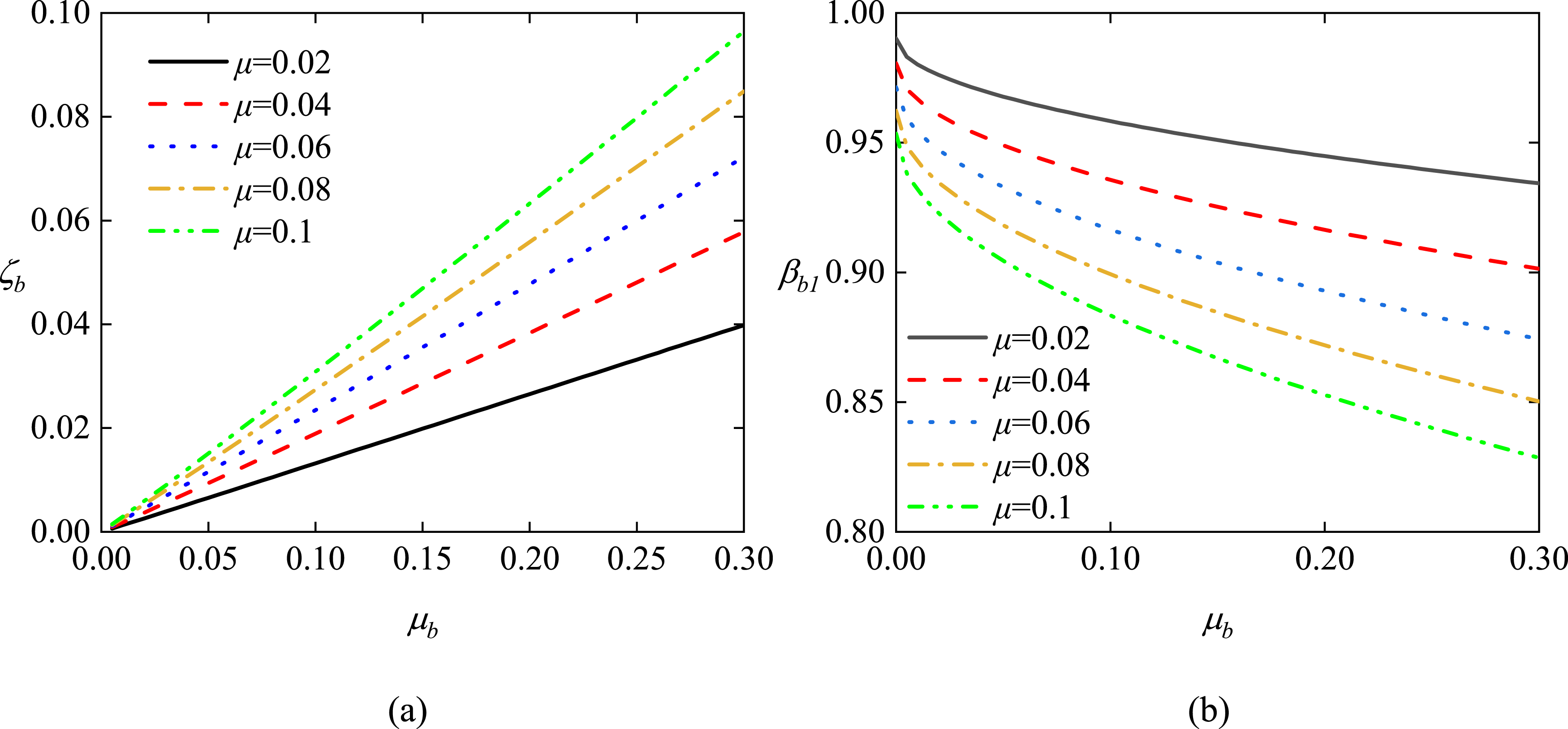
Influences of different parameters on the dynamic amplification factor are shown in Figure 7. Figure 7(a) shows the complementary relationship between μ
b
and α: for a constant dynamic amplification factor, an increase in μ
b
leads to a reduction in the absolute value of α because a large μ
b
has a sufficient negative stiffness effect, and the demand for negative stiffness correspondingly decreases. Figure 7(b) shows the variation in the maximum dynamic amplification factor with the mass ratios μ and μ
b
. The maximum dynamic amplification factor decreases significantly with increasing mass ratio μ, with a considerable reduction in magnitude, whereas the influence of the inertance-mass ratio μ
b
on the dynamic amplification factor is quite limited. Therefore, to enhance the vibration reduction performance of the controlled structure, priority should be given to increasing the mass ratio μ rather than the inertance-mass ratio μ
b
. Effects of different values of μ
b
, α and μ on the dynamic amplification factor: (a) Complementary relationship between μ
b
and α, (b) Maximum dynamic amplification factor.
5. Vibration damping performance
To verify the superiority of INTMD in vibration reduction control, a comparative analysis was conducted on the vibration reduction performances of TMD, Maxwell-TMD (Dai et al., 2021), and INTMD under harmonic, pedestrian-induced, and wind-induced excitations. For harmonic excitations and wind-induced excitations, the H∞ optimized parameters are employed for all three dampers.
5.1. Harmonic excitation
A comparison of the dynamic amplification factors among the uncontrolled system, TMD system, Maxwell-TMD system, and INTMD system is shown in Figure 8. As μ increases continuously, the effective range of the resonance region gradually widens. Within the resonance region, the INTMD performs better than the TMD and Maxwell TMD in all cases, except near λ = 1, where it is slightly worse than the Maxwell TMD but still better than the TMD. Figure 9 compares the dynamic amplification factors of the mass blocks in different systems for mass ratios μ of 0.005, 0.03 and 0.05. For the three mass ratios, the results demonstrate that the variation in the maximum dynamic amplification factors of the mass blocks across the three damping systems is less than 5%, indicating comparable operating space requirements. Comparison of the dynamic amplification factors of the controlled structure for different systems: (a) μ = 0.03; (b) μ = 0.05. Comparison of the dynamic amplification factors of mass blocks in different systems: (a) μ = 0.03; (b) μ = 0.05.
Figure 10 shows the variation patterns of the maximum dynamic amplification factors of the optimal TMD, Maxwell-TMD, and INTMD systems with respect to the mass ratio μ. The vibration reduction performance improvement rates of the INTMD system compared with those of the other two dampers under different values of μ are presented in Table 1. From Figure 10(a) and Table 1, the maximum h1 of the three systems gradually decreases with increasing mass ratio μ, and the control effect of the INTMD is significantly better than that of the conventional TMD and Maxwell-TMD, with an improvement of approximately 15%–20% in the range of μ = 0.003 to 0.05. From Figure 10(b), the maximum h
b
of the three systems is negatively correlated with μ, all exhibiting closely matched values within a 5% variation, thereby verifying their similar spatial demands. Maximum dynamic amplification factors of the TMD, Maxwell-TMD and INTMD systems as a function of the inertance-mass ratio: (a) controlled structures and (b) mass blocks. Vibration reduction performance improvement rate of the INTMD.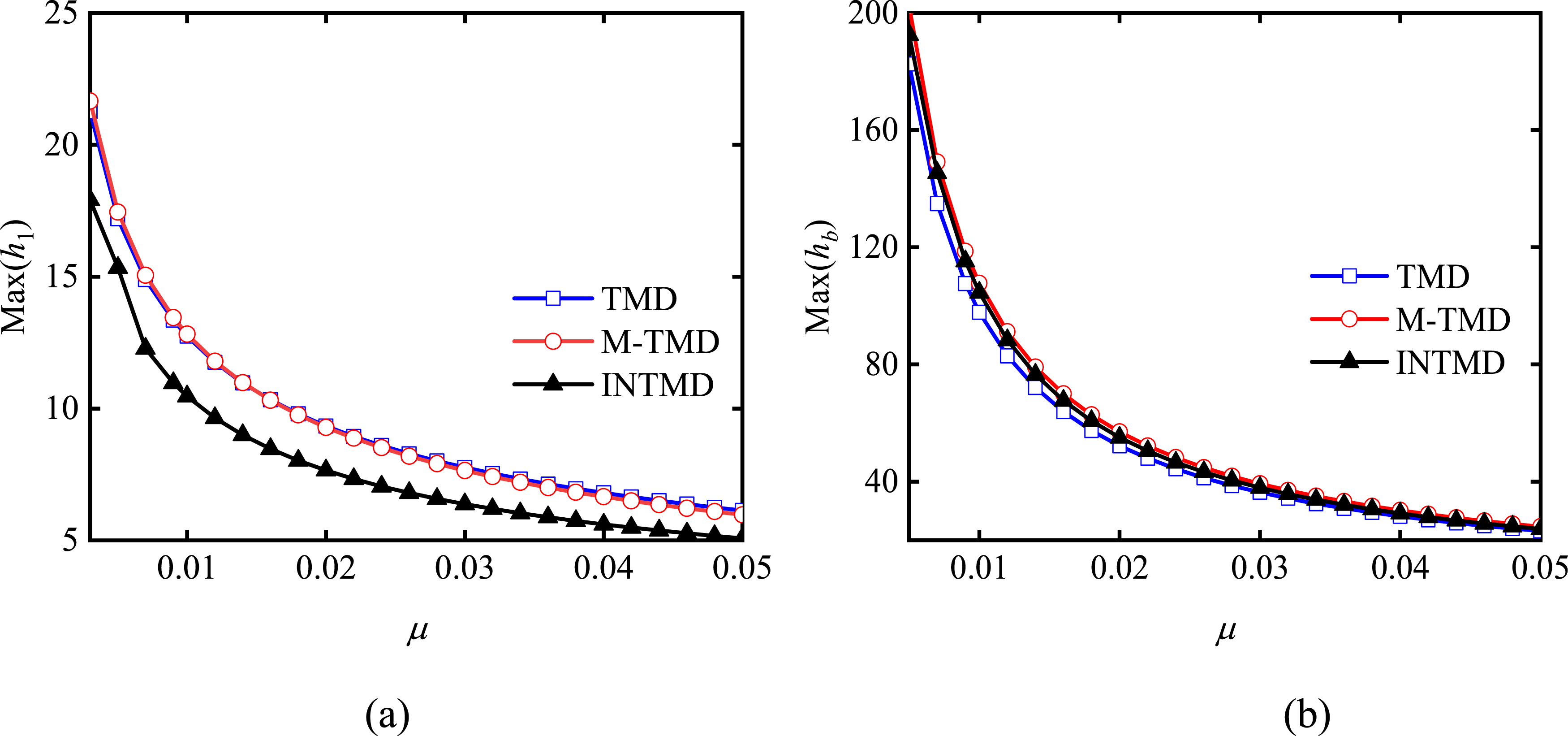
5.2. Wind-induced excitation
The vibration mitigation effect of the INTMD on a tall structure under fluctuating wind is examined through the analysis of a 243-m-high solar tower, where the outer diameter tapers from 23 m at the bottom to 20 m at the top. The part above 200 m in height is a steel structure with an outer diameter of 15 m. The first-order generalized mass and frequency are 4.27 × 10⁶ kg and 0.28 Hz, respectively, and the damping ratio (ζ
s
) is taken as 1.0%. The generalized fluctuating wind load of the first mode shape f(t) is as follows:
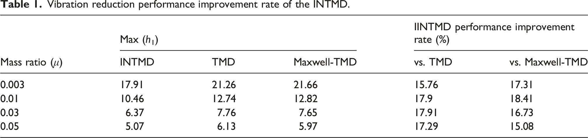
The nodal wind speed time history is simulated via the autoregressive model via the linear filtering method. These wind speed data are then converted into a wind load time history via the quasi-steady method, employing a shape coefficient of 1.3 and a basic wind pressure of 1.0 kN/m2. The resulting generalized fluctuating wind load for the first mode shape, obtained by substituting this load into equation (34), is presented in Figure 11. Generalized fluctuating wind load for the first mode of the structure.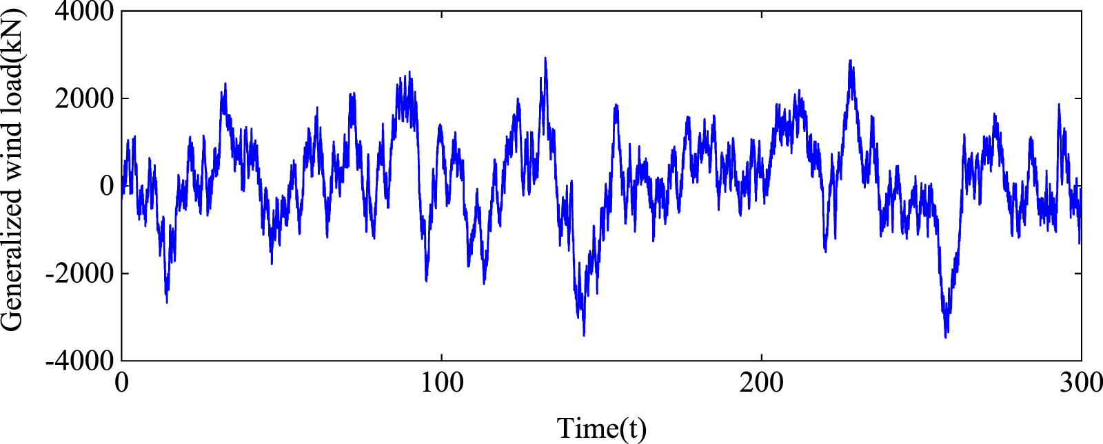
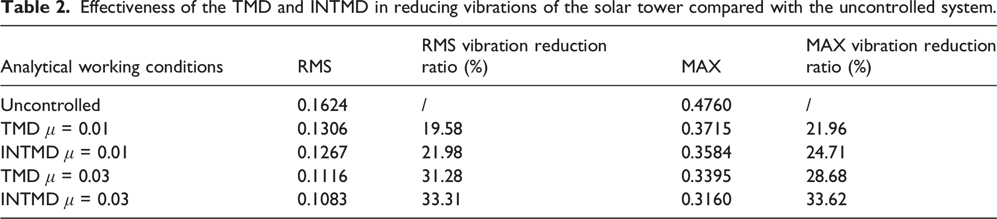
The structural fluctuating wind load is a random broadband excitation, and the H∞ optimization method can be adopted to optimize damper parameters for vibration reduction analysis. Figure 12 shows the time history of tower top displacement for uncontrolled systems, TMD systems, and INTMD systems of solar towers. Table 2 presents the displacement vibration reduction efficiency of the two damping systems compared with that of the uncontrolled system, including the root mean square (RMS) and absolute maximum value (MAX). Both damping absorbers significantly reduce the top displacement of the solar tower, with a larger mass ratio yielding better control performance. Furthermore, the INTMD demonstrates markedly superior vibration reduction to the TMD in terms of both the RMS and maximum values of the vibration response. Hence, the INTMD is recommended as a favorable replacement for the TMD in tall structures to achieve enhanced control effectiveness. Wind direction displacement time history at the top of the solar tower (a) μ = 0.01 (b) μ = 0.03. Effectiveness of the TMD and INTMD in reducing vibrations of the solar tower compared with the uncontrolled system.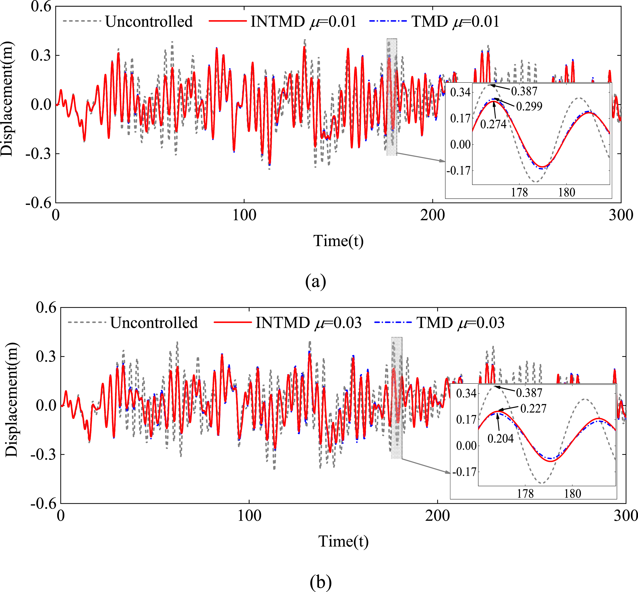
6. Conclusions
In this research, a comprehensive exploration of the INTMD for structural vibration control is conducted, encompassing dynamic modeling, parameter optimization, parametric analyses, and performance validation under multi-type excitations. First, the motion equation, dynamic amplification factor, and stability conditions of the SDOF-INTMD system are derived. Then, the optimal parameters of the INTMD are obtained via the H∞ criteria, followed by in-depth parametric analyses. Finally, the vibration reduction performance of the INTMD is quantitatively evaluated under harmonic and wind-induced excitations, with comparisons to the conventional TMD and Maxwell-TMD. The core findings of this study are summarized as follows: (1) Closed-form expressions for the dynamic amplification factor and stability conditions of the SDOF-INTMD system provide a rigorous theoretical basis for parameter optimization and engineering applications. (2) An individual increase in either the inertance-mass ratio or the negative stiffness ratio, which are complementary in the INTMD, fails to significantly improve the vibration suppression performance. An increase in the mass ratio of INTMD is a more effective strategy for controlling performance enhancement than an increase in the inertance-mass ratio. (3) INTMD is more sensitive to variations in the inertance-mass and tuning frequency ratios than to the mass, negative stiffness, and damping ratios, necessitating careful design of the spring stiffness and inertance in practical applications. (4) The superiority of the INTMD in vibration reduction over both the TMD and the Maxwell TMD under harmonic and pedestrian-induced excitations is most pronounced around the resonance region, particularly when the excitation frequency is slightly detuned from the structural natural frequency. (5) For wind-induced fluctuating loads, the INTMD outperforms the traditional TMD in controlling displacement responses, and this advantage becomes more significant with increasing mass ratio. (6) The spatial requirements of the INTMD are comparable to those of the TMD and Maxwell TMD, making it a direct replacement for these dampers in structures such as footbridges and tall buildings.
Footnotes
Author contributions
Yu-ji Tai: Investigation, Conceptualization, Funding acquisition, Data curation, Writing—original draft. Dao-guang Liu: Investigation, Writing—review and editing. Lu-lu Cheng: Validation. Qing Wen: Validation. Wei Chen: Validation.
Funding
The authors disclosed receipt of the following financial support for the research, authorship, and/or publication of this article: The work described in this paper is supported by the National Natural Science Foundation of China (Grant No. 52508525), the Hunan Provincial Key Laboratory of Structural Wind Resistance and Vibration Control (Hunan University of Science and Technology) (Grant No. E22530), the Henan International Joint Laboratory of Dynamics of Impact and Disaster of Engineering Structures (Grant No. DIDES-2024-B4), the Chongqing Three Gorges Reservoir Bank Slope and Engineering Structure Disaster Prevention and Control Engineering Technology Research Center (Grant No. SXAPGC25YB01), and the Guangdong Provincial Key Laboratory of Intelligent Disaster Prevention and Emergency Technologies for Urban Lifeline Engineering (2022) (Grant No. 2022B1212010016).
Declaration of conflicting interests
The authors declared no potential conflicts of interest with respect to the research, authorship, and/or publication of this article.
Data Availability Statement
No data was used for the research described in the article.