
Abstract
To elucidate the intrinsic mechanism of vibration suppression induced by roller pitch diameter modification in planetary roller screw mechanism (PRSM), a coupled dynamic model incorporating modification effects is developed. The influence of different modification magnitudes on the vibration response of key components is systematically investigated. First, based on helical surface contact theory, a thread contact model considering roller modification is established. The clearance distribution induced by the modification is introduced into the load distribution analysis as the initial condition. Subsequently, Hertzian contact theory is employed to obtain the non-uniform load distribution. A lubricated sliding friction model for the roller–screw interface is further established and incorporated into the dynamic equations as an excitation source. By analyzing the spatiotemporal evolution of friction forces under different modification levels, the vibration suppression mechanism is clarified. Finally, the proposed model is validated through model degeneration analysis and experimental comparisons, confirming its reliability and accuracy. However, the synergistic vibration suppression effect of gear pair modification and thread pair modification was not considered in the present study. Future work will focus on establishing a coupled modification model of the thread pair and gear pair to further reveal the vibration suppression mechanism and vibration characteristics of PRSM.
Keywords
1. Introduction
The planetary roller screw mechanism (PRSM) structure is shown in Figure 1, it has been widely applied in aerospace, high-end CNC equipment, and electromechanical actuation systems due to its superior load-carrying capacity, superior transmission accuracy, and suitability for high-speed and heavy-load operating conditions (Chen, 2019; Zhang et al., 2024). Schematic representation of the PRSM structure.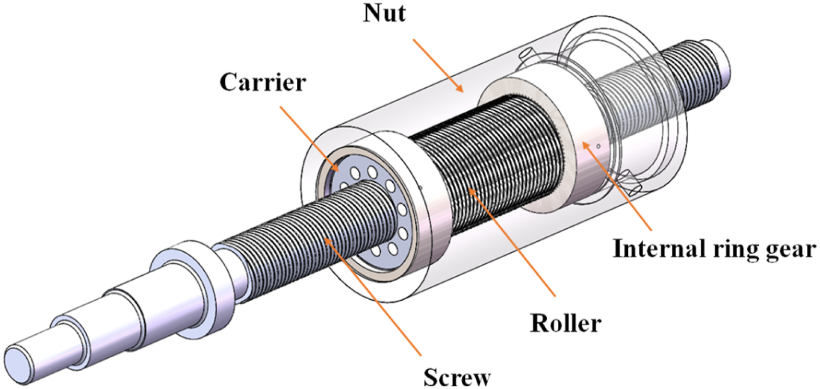
With the increasing demand for high-speed, high-precision, and low-noise transmission systems, vibration and noise in PRSM have become key factors limiting their performance and engineering applications. Existing studies indicate that the primary excitation sources originate from contact nonlinearity and friction within internal transmission pairs, especially the sliding friction in the roller–screw thread pair (Fu et al., 2018). However, the vibration generation mechanism caused by the coupling of friction and contact nonlinearity, as well as corresponding vibration suppression methods, has not been systematically studied. Therefore, it is necessary to investigate the friction-induced vibration characteristics and suppression mechanisms of PRSM to support the optimal design and low-vibration operation of high-performance systems. In this study, only the thread pair modification is considered, as it is the primary load-bearing and sliding contact interface governing the dominant friction-induced excitation. The gear pair is assumed unmodified due to its relatively small contact force, and thus limited influence on the overall vibration response. This simplification enables the model to focus on the dominant vibration mechanism while maintaining physical relevance.
To address vibration issues in PRSM, previous studies have mainly focused on dynamic modeling, load distribution, and lubrication characteristics. In dynamic modeling, Wu et al. developed a torsional model based on contact behavior and performed modal analysis (Wu et al., 2020), and later improved it by incorporating deformation effects (Wu et al., 2024). Mo et al. established a dynamic model considering time-varying gear meshing stiffness and investigated system stability under different operating conditions (Mo et al., 2024). Xu et al. developed a load distribution model including gear meshing excitation and found that time-varying meshing stiffness induces periodic variations in thread load distribution (Xu et al., 2026).
Regarding load distribution of thread pair, Zhang et al. was first introduced in load distribution models under different installation configurations, although the load sharing among rollers was not considered (Zhang et al., 2016). To address this limitation, Xing et al. introduced a multi-roller load-sharing model for PRSM (Xing et al., 2024a). In addition, various load equalization methods have been studied. Yao et al. presented an optimization approach to realize the most uniform load distribution through lead design (Yao et al., 2022). Fu et al. found that load-sharing characteristics are exhibits higher sensitivity to the positional relationship between the screw and nut, while being less sensitive to roller position errors (Fu et al., 2017).
Regarding friction and lubrication, Xing et al. developed a kinematic model of PRSM to analyze the effects of structural and operating parameters on sliding velocity and direction at the roller–screw and roller–nut interfaces (Xing et al., 2023). Xie et al. established a mixed-lubrication model and systematically studied the effects of rotational speed, load, and surface roughness on lubrication performance (Xie et al., 2019). They further developed a Lagrangian-based friction–dynamic model to investigate the influence of operating conditions and creep parameters on friction torque, transmission efficiency, and relative sliding velocity (Xie et al., 2023). In addition, Xing et al. derived entrainment velocity, oil film thickness, and pressure distribution considering eccentricity error and analyzed their effects on lubrication characteristics (Xing et al., 2024b).
Significant progress has been made in understanding the effects of friction and lubrication on the vibration behavior of transmission systems from tribological and dynamic perspectives. Liu et al. investigated the dynamic behavior of rolling bearings based on elastohydrodynamic lubrication (EHL) theory and Hertzian contact mechanics (Liu et al., 2025). Zhang et al. analyzed the vibration characteristics of rotor–bearing systems under high-temperature conditions by combining tribology and dynamics (Zhang et al., 2022). Li et al. proposed a method for calculating time-varying friction torque in ball bearings (Li et al., 2026), while Sulollari et al. established the relationship between friction and vibration using a mass–spring–damper model (Sulollari et al., 2024). In addition, Kumar et al. developed a control strategy to suppress stick–slip vibration in single-degree-of-freedom systems (Kumar and Malas, 2024). Khaldoon F. developed gear dynamic models showing that tooth surface friction significantly enhances vibration response in the off-line-of-action direction (Khaldoon et al., 2015), and further demonstrated that considering elastohydrodynamic lubrication, changes in lubricant viscosity significantly alter the vibration response of the gear system by affecting the friction coefficient (Khaldoon et al., 2022).
Existing studies often treat contact geometry, load distribution, and friction behavior independently, lacking a coupled framework along “structural modification–contact state–lubrication friction–dynamic response.” Roller pitch diameter modification introduces axial contact clearance, regulating load distribution and improving friction conditions; however, its influence on friction excitation and vibration response remains unclear. This study develops coupled contact and load distribution models incorporating modification, and integrates lubricated sliding friction into the dynamic equations for unified modeling. Based on this framework, the effects of modification magnitude on contact state, friction evolution, and vibration response are systematically analyzed, revealing the underlying vibration suppression mechanism.
2. Contact characteristics and clearance of thread pairs
The load distribution of PRSM thread pairs shows that the roller–screw contact force decreases with increasing thread index, while the roller–nut contact force increases. Due to axial reciprocating motion, contact forces are highest at both ends of the roller threads. Therefore, reducing end contact forces is crucial for improving load capacity, reducing friction, and suppressing vibration.
During the machining of the threads located at both ends of the roller, the pitch diameter of the threads is reduced by increasing the feed rate. This machining approach is referred to as roller pitch diameter modification. After modification, the contact relationship between the roller and the screw/nut threads is illustrated in Figure 2. Contact relationship after roller pitch diameter modification.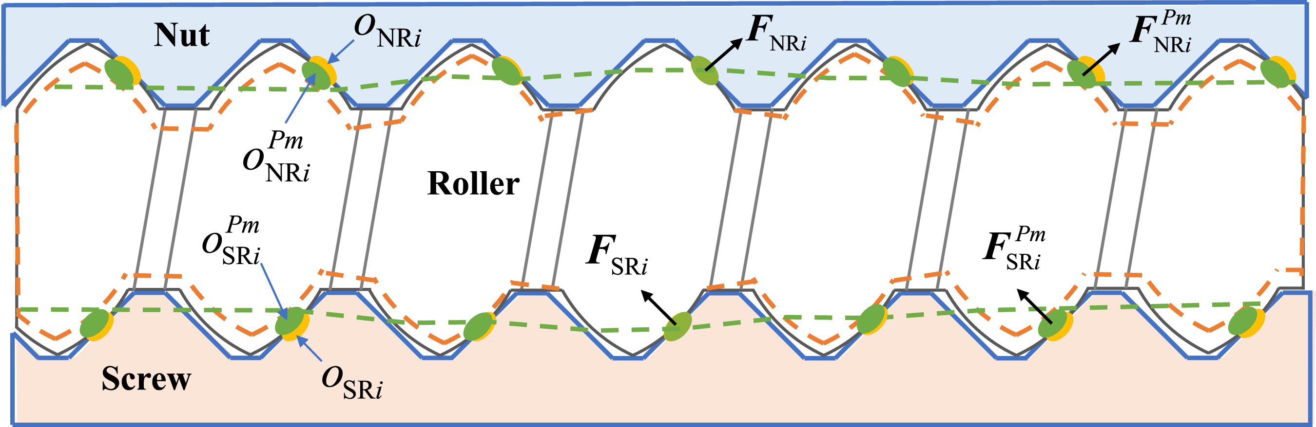
As shown in Figure 2, the axial clearance between the modified roller end threads and the screw/nut threads increases. This enlarged axial clearance delays the engagement of the roller end threads, thereby reducing the corresponding contact forces.
A coordinate system Profile of the roller with modified threads.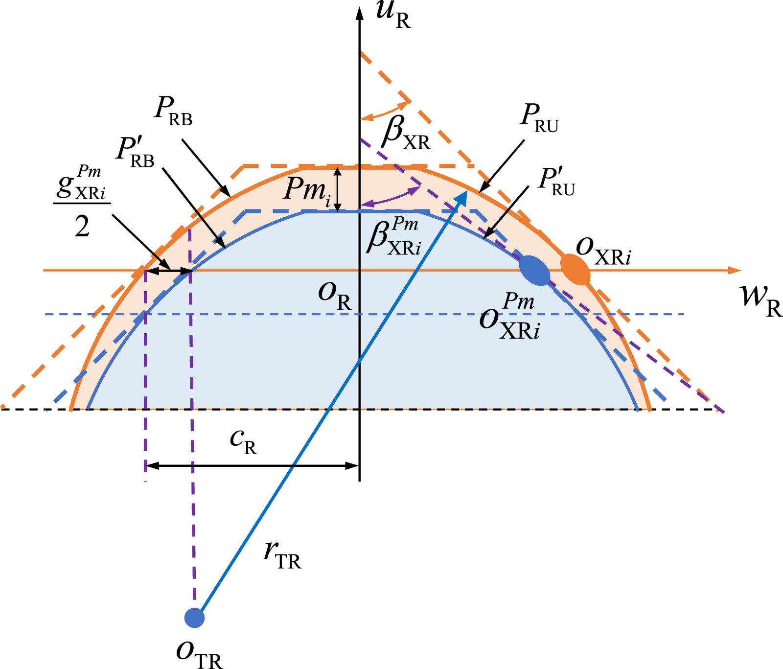
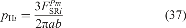
According to Figure 3, when the roller pitch diameter is reduced by
The coordinates

The equation of the modified roller arc
When

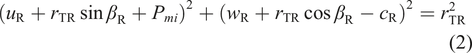
The increment in axial clearance after modification is twice the distance between
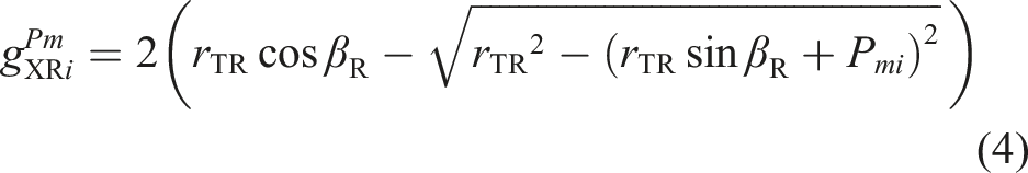
By differentiating equation (2), we obtain
Substituting the coordinates of point
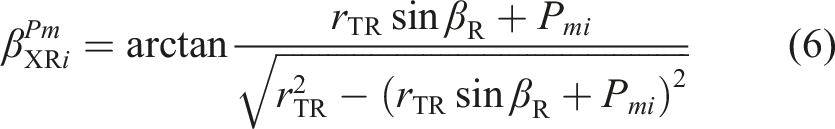
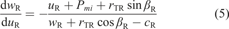
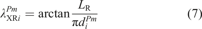
The helix angle
According to existing literature (Fu et al., 2016), the clearances between the unmodified roller–screw and roller–nut thread pairs can be calculated using Equations (8)–(11)

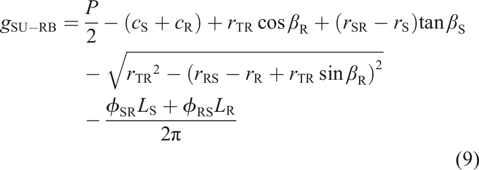


After modification, the clearance between the roller–screw and roller–nut thread pairs is equal to the sum of the original clearance and the additional clearance induced by modification, as expressed in equation (12)

3. Load distribution and friction force
3.1. Load distribution
To evaluate the friction force after roller pitch diameter modification, the contact force distribution must first be determined. In this study, modification at both roller ends increases axial clearance, leading to delayed engagement. The introduced clearance is treated as a compensation for elastic deformation and incorporated into the load distribution model. Based on this, the modified load distribution is calculated using Hertzian contact theory.
The elastic deformation of a thread tooth is equal to the global axial deformation of the system minus the thread clearance after roller pitch diameter modification.
The relationship between thread contact deformation and thread clearance is expressed as

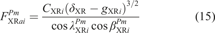
The Hertzian contact force of the PRSM thread pair can be derived based on Hertzian contact theory. Therefore, the contact force of the modified roller and screw or roller and nut thread pair is given by:

According to the force analysis of the PRSM, the axial contact force of each thread tooth after roller pitch diameter modification can be expressed as
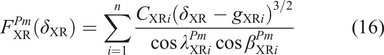
Thus, the contact force of the roller and screw or roller and nut thread pair after modification is given in equation (16)
Before solving the thread tooth contact forces, a contact detection step is performed for each thread tooth to ensure that all teeth participating in engagement undergo elastic deformation, that is,

An initial value of the global deformation of the roller and screw or roller and nut system is set as the sum of the minimum thread clearance and the convergence tolerance, as expressed in equation (18)

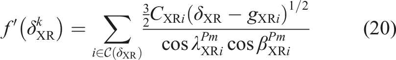
A nonlinear equation is then established based on the contact force formulation, as shown in equation (19)
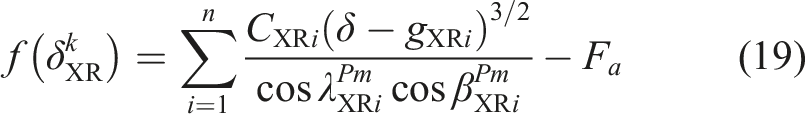
The derivative of the contact force function at the contact point between the roller and the screw/nut is obtained as
The Newton–Raphson iteration scheme is applied

Finally, a convergence criterion is defined for the iterative solution

Based on the load non-uniformity coefficient for PRSM thread pairs reported in Zhang et al. (2016), the contact forces of the R–S and R–N thread are expressed as

Accordingly, the load distributions of the roller–screw and roller–nut thread pairs considering load equalization can be obtained from equation (24).
3.2. Friction force
Due to relative sliding between the roller and the screw and pure rolling between the roller and the nut, the roller–screw interface exhibits combined rolling and sliding friction. Since rolling friction is negligible compared to sliding friction, this study neglects rolling friction and roller–nut friction, considering only the sliding friction at the roller–screw interface. The sliding friction force is expressed as

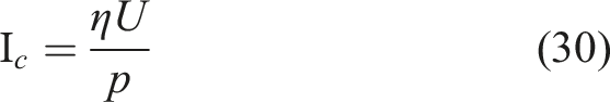
The sliding contact in PRSM roller–screw threads is analogous to bearing contacts, and the friction coefficient can be described using a typical Stribeck curve (Wen and Huang, 2018). As shown in Figure 4, the bearing friction coefficient varies with the bearing characteristic number, corresponding to boundary, mixed, and hydrodynamic lubrication regimes. Stribeck curve of the bearing.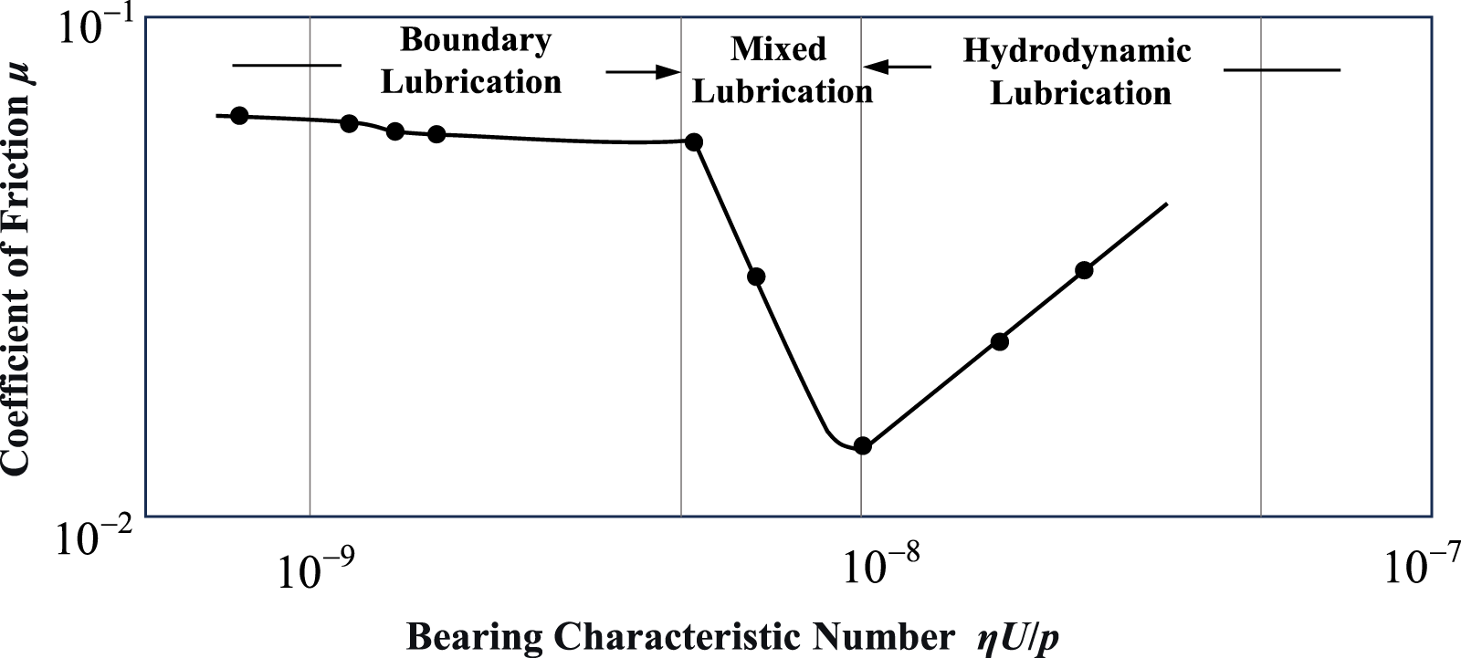
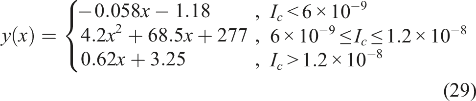
Based on the friction coefficient curves under different lubrication regimes shown in Figure 4, the friction coefficient function is obtained through curve fitting, as expressed in Equations (28) and (29)

The sliding velocity at the contact interface of the screw–roller pair thread is given by

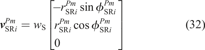
Specifically,
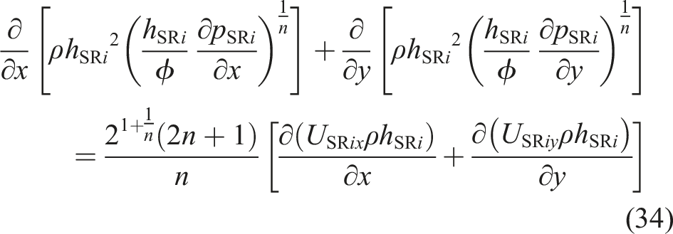
Based on the flow separation method for solving non-Newtonian lubrication problems, the Reynolds equation for the Ostwald non-Newtonian fluid model can be derived as
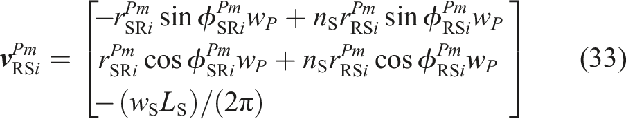
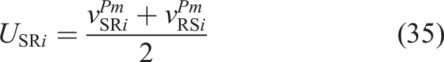
Based on the relative sliding velocity between the roller and screw, the entrainment velocity at contact point is formulated as
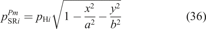
When the PRSM is loaded, elastic deformation and contact stress occur at the roller–screw interface, and the contact region forms an elliptical area. The contact stress at an arbitrary point in the elliptical contact region of the i-th thread tooth is formulated as
By substituting the entrainment velocity
4. Effect of profile modification on the vibration characteristics of PRSM
4.1. Dynamic model
Friction in the roller–screw contact interface is recognized as the dominant source of excitation governing the steady-state vibration of the PRSM system, with sliding friction being the primary contributor. In this study, only the roller–screw interface is considered for modification analysis, while the gear pair is assumed to remain unmodified, since its contribution to vibration excitation is relatively minor compared with the sliding contact behavior of the thread interface.
Based on this assumption, the contact and sliding characteristics under roller pitch diameter modification are first analyzed, and a corresponding sliding friction model is established. The friction-induced excitation is then incorporated into the dynamic equations to develop a lumped-parameter dynamic model of the PRSM considering modification effects. The model is formulated using the lumped mass method combined with force equilibrium analysis and is used to investigate the vibration responses of key components, providing a theoretical basis for structural optimization and vibration reduction.
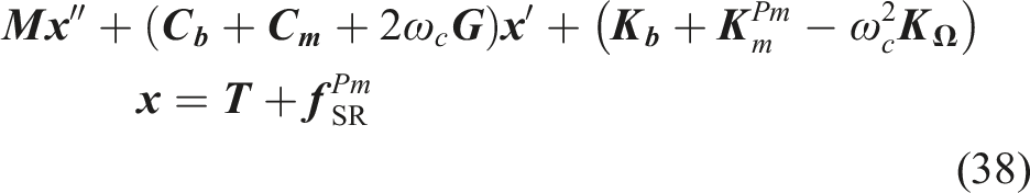
The governing dynamic equation of the PRSM is given in equation (38)
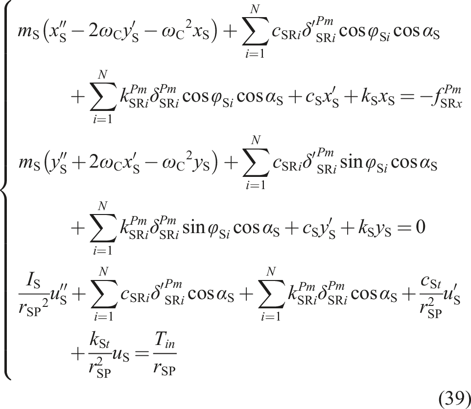
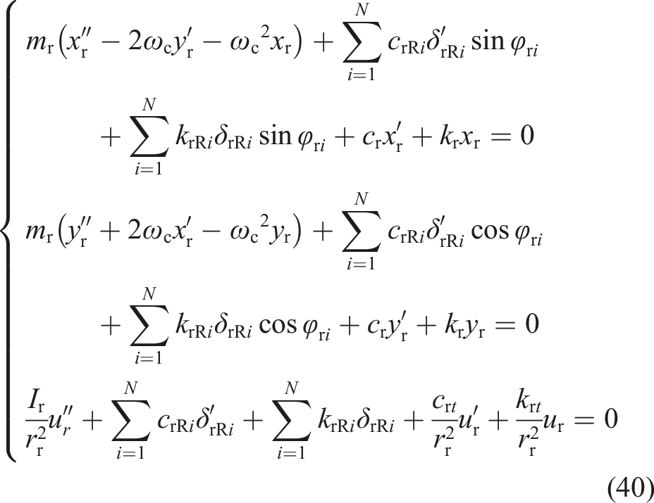
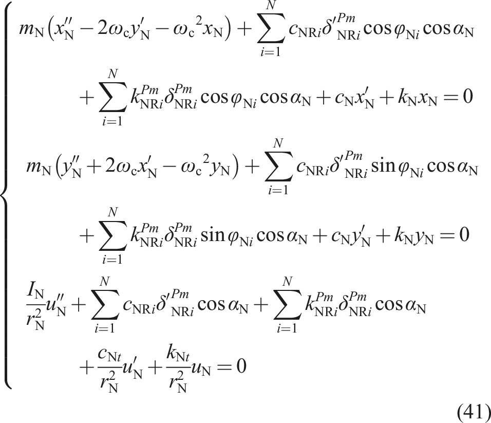
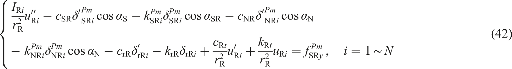
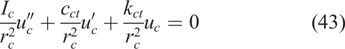
The governing equation of motion for the screw is expressed in equation (39), the internal ring gear in equation (40), the nut in equation (41), the roller in equation (42), and the carrier in equation (43), respectively
The formulations of the displacement vectors, damping matrices, time-dependent meshing stiffness of the gear pair, gyroscopic matrix, and radial stiffness matrix in the PRSM dynamic model can be found in Xu et al. (2026) and are not repeated here for brevity.
4.2. Numerical example
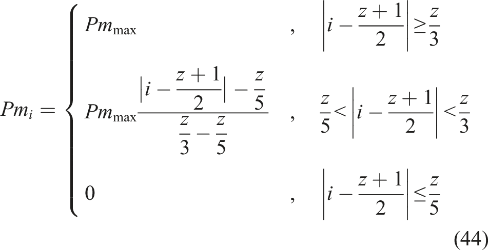
The roller pitch diameter modification is mainly applied to the threads at both ends of the roller, while the threads in the middle remain unmodified.
The roller threads are divided into five segments, and the modification amount for each segment is defined as
PRSM parameters.
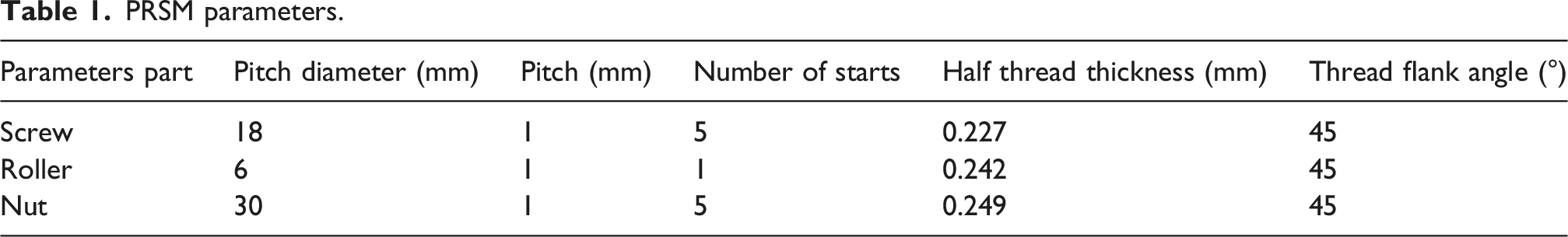
The maximum modification amount Effect of roller pitch diameter modification on thread pair clearance. (a) Clearance of roller–screw thread pair (b) Clearance of roller–nut thread pair.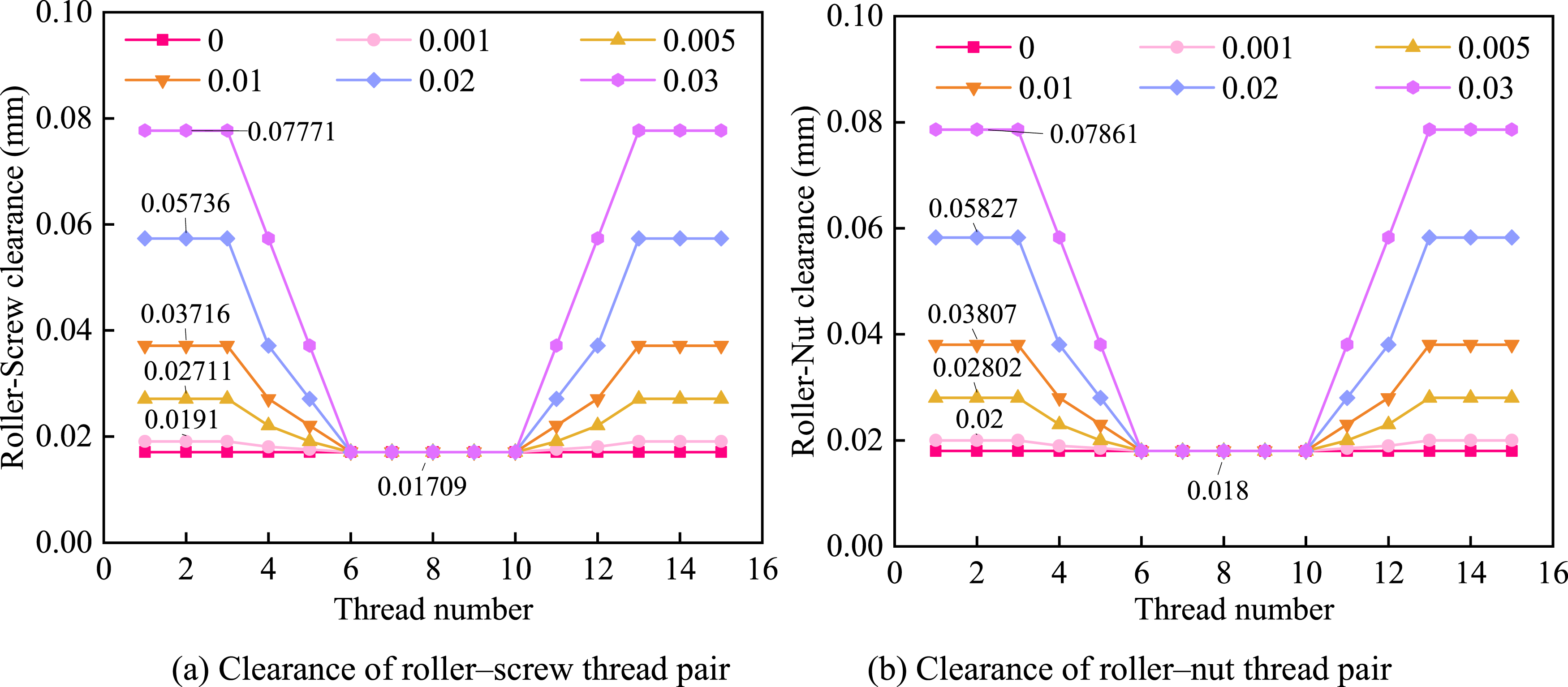
Figure 5 shows the influence of roller pitch diameter modification on the thread clearance. It can be observed that the clearance distribution is consistent with the modification distribution: the clearance is largest at both ends of the roller threads, while the middle threads maintain the same clearance as the unmodified case. This distribution delays the contact of the end threads, thereby reducing the contact force in the thread pairs.
Since this study focuses on the vibration suppression effect of roller pitch diameter modification, the non-uniform load distribution among rollers is neglected, and the nut load is assumed to be evenly distributed. A nut load of 50 kN and 10 rollers are considered. By substituting the modified clearance, contact angle, and helix angle into Equations (13)–(24), the load distributions of the thread pairs under different modification amounts are obtained, as shown in Figure 6. Effect of roller pitch diameter modification on thread pair load distribution. (a) Load distribution of roller–screw thread pair (b) Load distribution of roller–nut thread pair.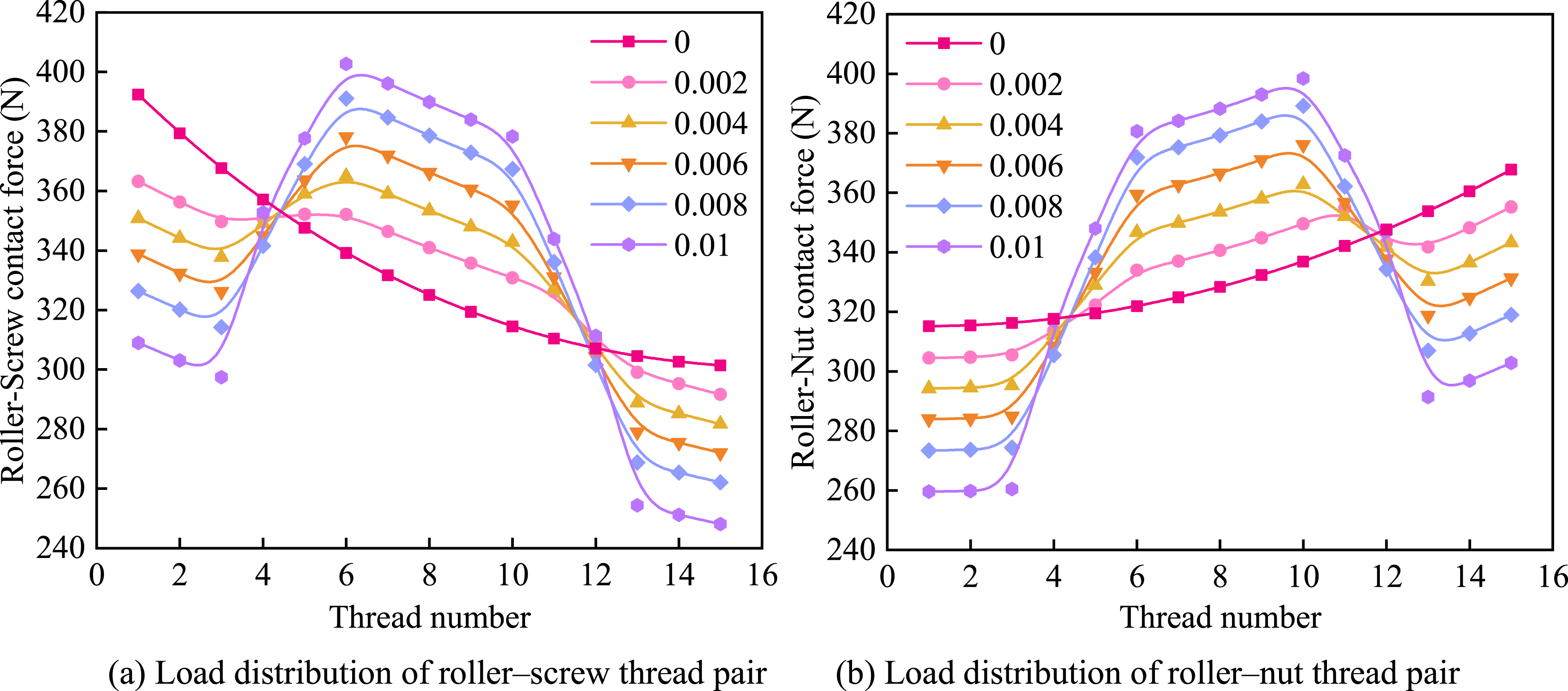
According to Figure 6, roller pitch diameter modification effectively reduces the contact force at the end threads of both the roller–screw and roller–nut pairs, with a more pronounced reduction observed on the roller–screw side.
As the modification increases, the maximum contact force at the middle threads of the roller–screw pair exceeds the unmodified case at 0.01 mm, while a similar trend occurs for the roller–nut pair at 0.006 mm. However, since the roller–screw contact force is significantly higher, it is taken as the governing criterion. Therefore, the maximum allowable modification is selected as 0.01 mm.
After obtaining the contact angles and load distributions under roller pitch diameter modification and the grease viscosity Effect of roller pitch diameter modification on the friction coefficient of the roller–screw thread pair.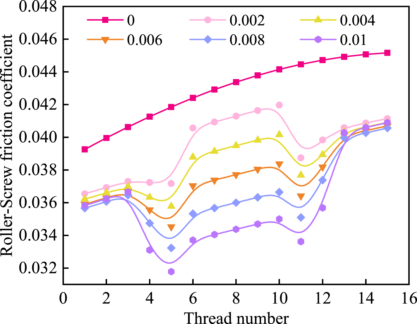
As shown in Figure 7, the friction coefficient of the roller–screw thread pair decreases after roller pitch diameter modification. This is because the contact point shifts toward the thread crest, increasing contact stress and lubricant film pressure, while the sliding velocity between the roller and screw is reduced. The combined effect leads to a lower bearing characteristic number and reduced friction coefficient, indicating that the PRSM operates in the hydrodynamic lubrication regime under the present conditions.
By incorporating the sliding friction force of the roller–screw thread pair into the PRSM dynamic model, the vibration accelerations of various components after roller pitch diameter modification are obtained, as shown in Figures 8–11. Effect of roller pitch diameter modification on the vibration acceleration of screw. (a) Screw x vibration acceleration (b) Screw y vibration acceleration (c) Screw u vibration acceleration. Effect of roller pitch diameter modification on the vibration acceleration of nut. (a) Nut x vibration acceleration (b) Nut y vibration acceleration (c) Nut u vibration acceleration. Effect of roller pitch diameter modification on the vibration acceleration of roller. (a) Roller x vibration acceleration (b) Roller y vibration acceleration (c) Roller u vibration acceleration. Effect of roller pitch diameter modification on the vibration acceleration of ring gear. (a) Internal ring gear x vibration acceleration (b) Internal ring gear y vibration acceleration (c) Internal ring gear u vibration acceleration.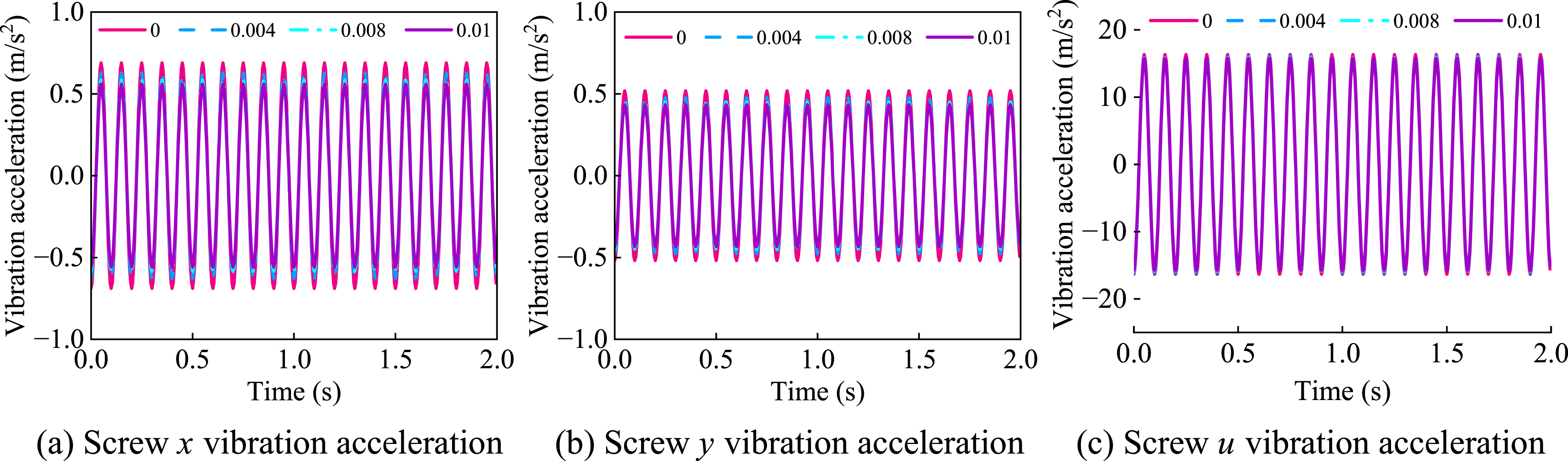
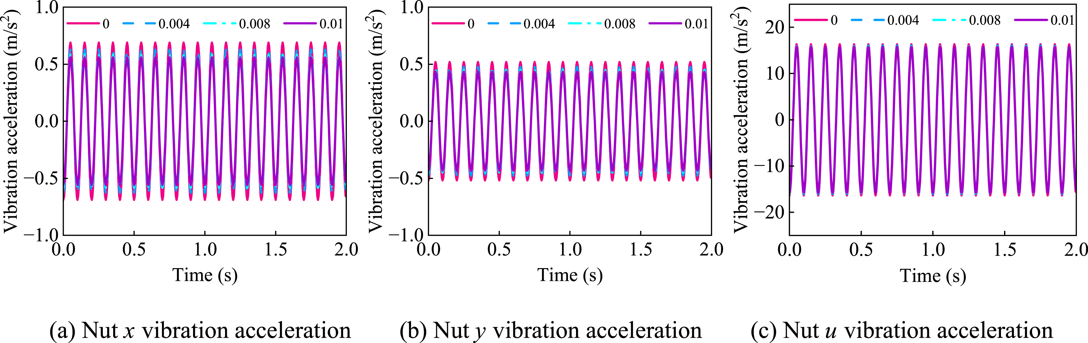
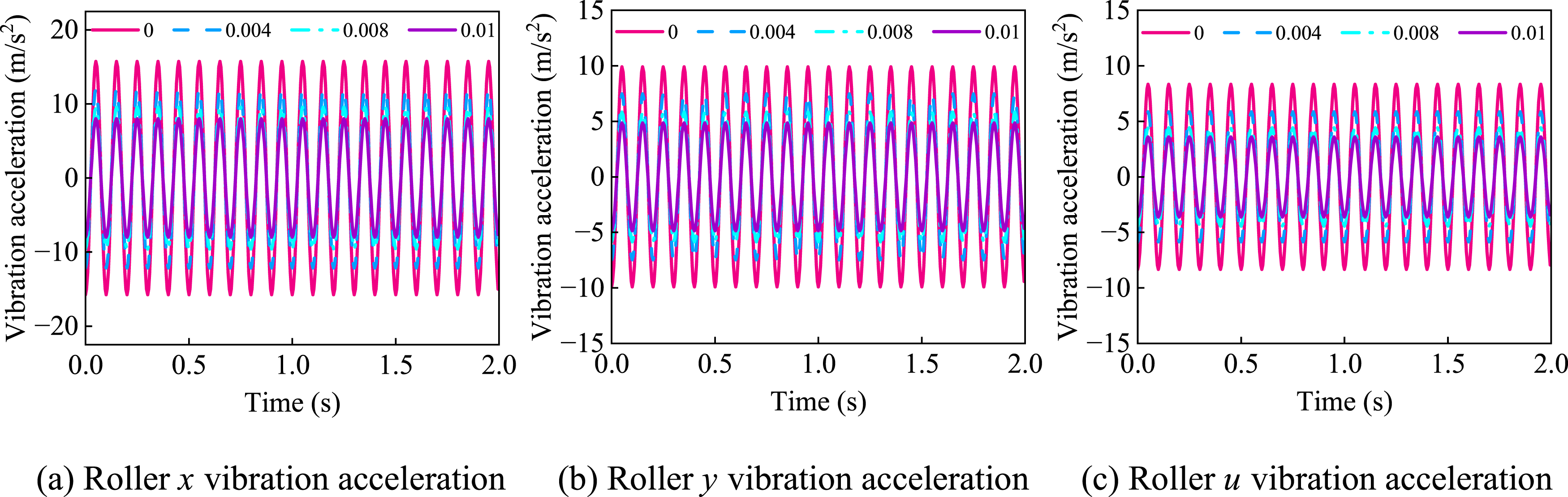
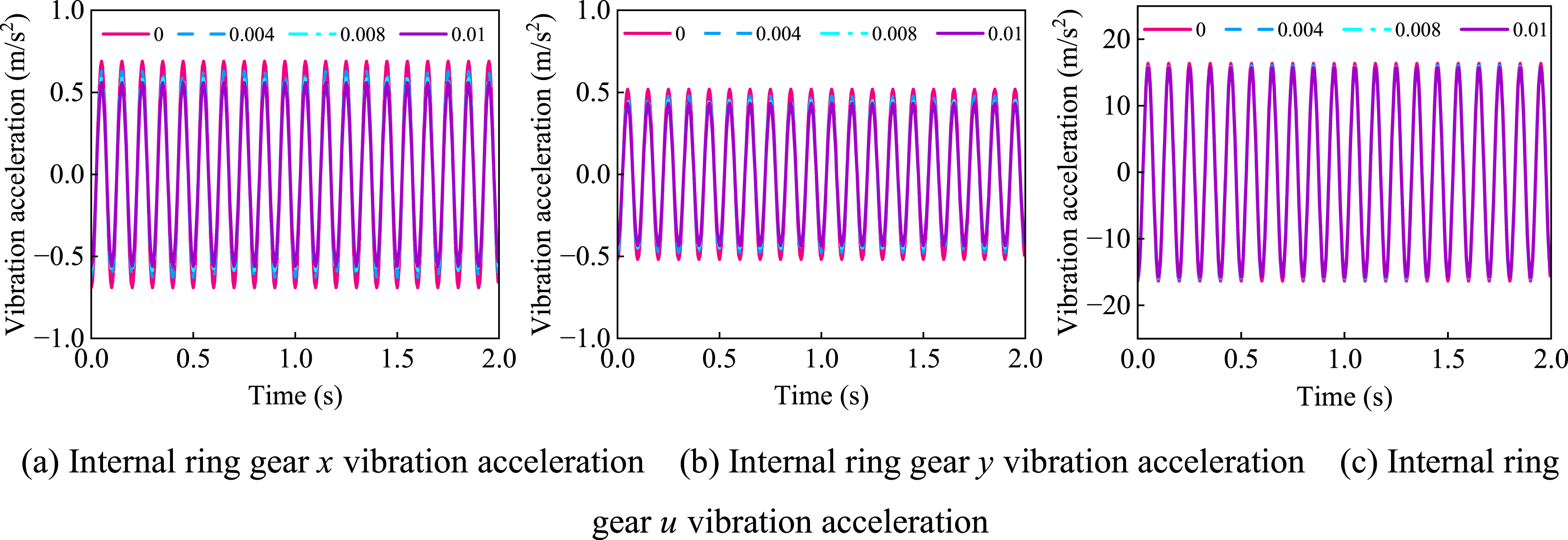
As shown in Figures 8–11, due to the combined excitation of thread contact and gear meshing, the roller exhibits the highest vibration acceleration. In addition, in this rotational transmission system, the torsional vibration is significantly greater than the tangential and radial components. After applying roller pitch diameter modification, the vibration amplitudes of all components are reduced, among which the reductions for the screw (tangential and radial directions) and the roller are the most significant. This is mainly attributed to the increase in thread clearance and the reduction in contact deformation after modification, which decrease the contact force and consequently reduce the sliding friction coefficient and friction force. When the modification amount is 0.01 mm, the tangential acceleration of the roller decreases from 15.7 m/s2 to 8.01 m/s2, corresponding to a reduction of 48.98%, indicating that the proposed method achieves an effective vibration suppression effect.
4.3. Model validation
Since accurate reference results for load distribution of modified threads are not available, a model degradation approach is adopted by setting the roller pitch diameter modification to zero and comparing the results with those reported by Zhang et al. (2016). Under identical structural parameters and operating conditions, the load distributions of the unmodified roller–screw and roller–nut pairs are calculated, as shown in Figure 12. Comparison of load distribution calculation results.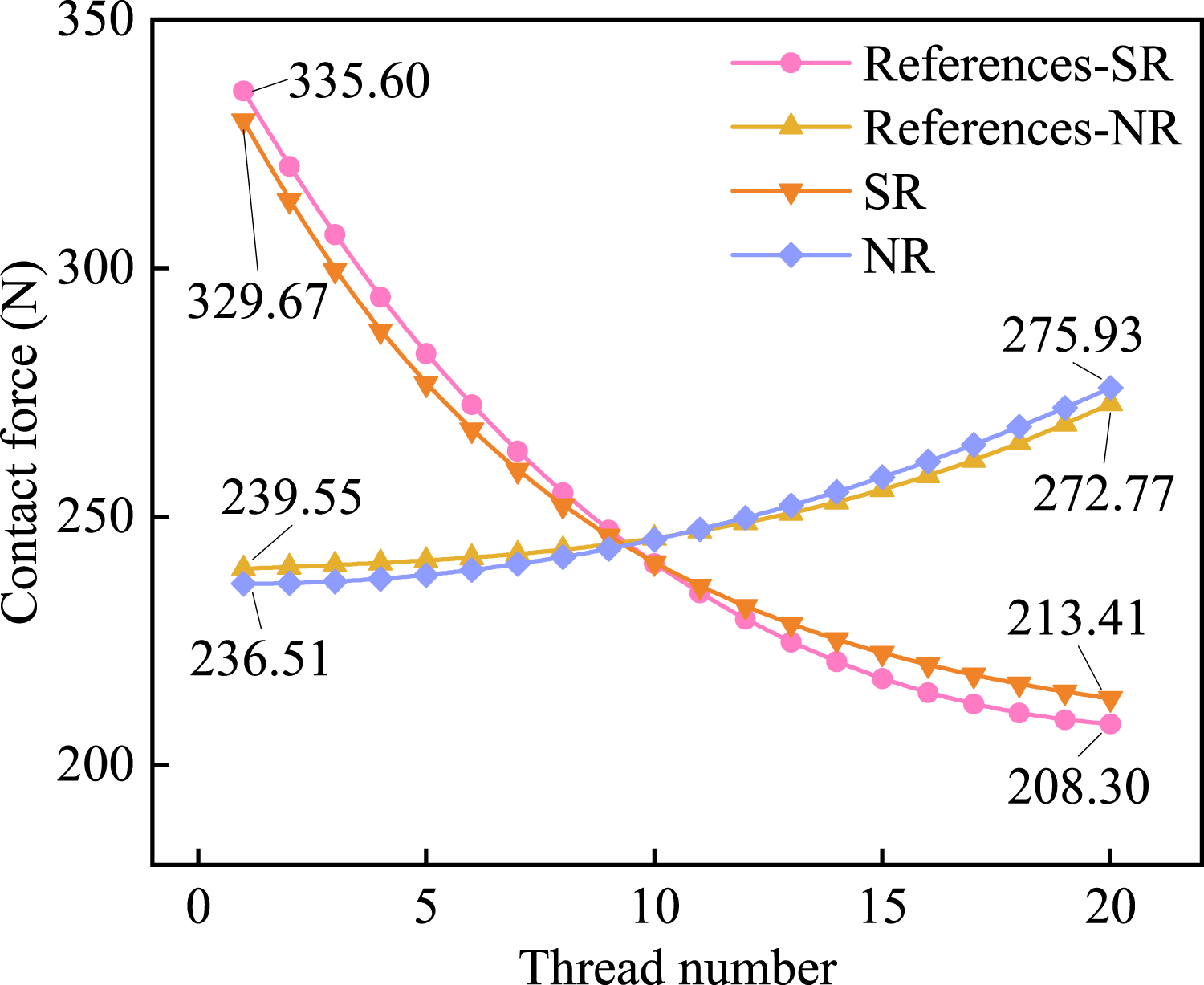
As shown in Figure 12, the calculated load distributions agree well with published results in both trend and magnitude, with maximum relative errors of 2.45% for the roller–screw pair and 1.27% for the roller–nut pair. The slightly larger deviation in the roller–screw case is mainly due to the inclusion of the contact misalignment angle, which was neglected in the reference, as well as differences in stiffness modeling. Previous studies indicate that Hertzian contact stiffness accounts for about 97% of the total thread pair stiffness in PRSM; thus, only Hertzian contact stiffness is considered in this study, while bulk stiffness is neglected.
To further validate the proposed dynamic model considering friction, experimental measurements of the nut vibration acceleration are conducted. Due to the high cost and time required for roller modification, a degradation experimental validation is performed. The measured vibration acceleration of the unmodified nut is evaluated against the theoretical results to verify the accuracy of the model. The experimental setup for measuring vibration acceleration is shown in Figure 13. Experimental setup for vibration acceleration of the PRSM.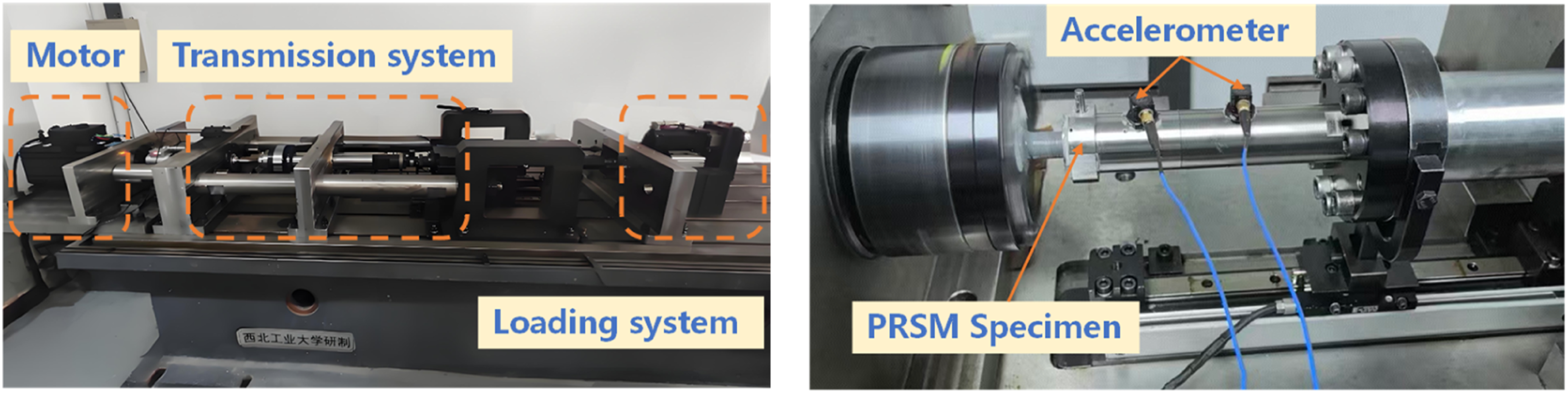
As shown in Figure 13, the test rig consists of a motor, loading system, transmission system, a well-lubricated test specimen, and vibration acceleration sensors. The accelerometer is mounted on the surface of the nut to measure its radial vibration acceleration.
To ensure repeatability, the vibration acceleration of the nut is measured twice. The screw is operated at a rotational speed of 500 r/min, and the sampling frequency of the acceleration sensor is 200 Hz. The two sets of measured radial vibration acceleration results are shown in Figure 14(a). The corresponding theoretical results are presented in Figure 14(b). Nut radial vibration acceleration. (a) Experimental results (b) Calculated results.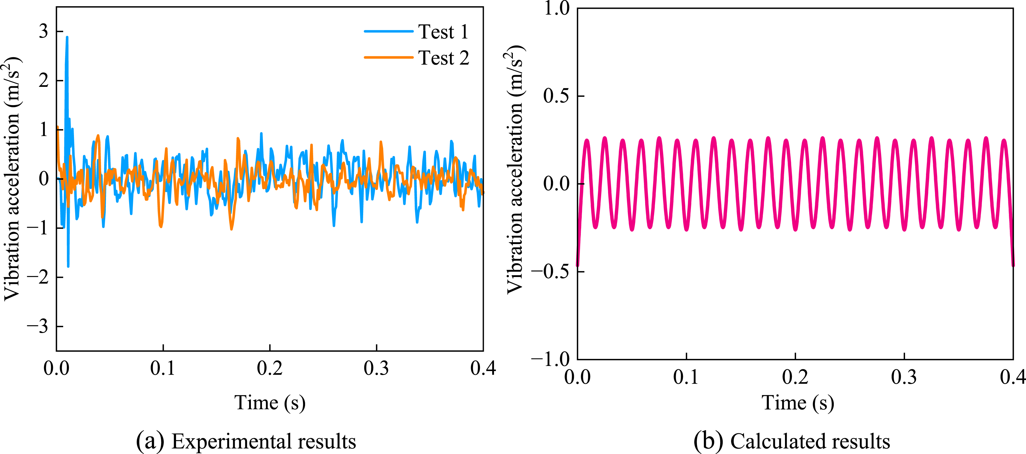
As shown in Figure 14(a), a sudden increase in vibration acceleration occurs at startup due to the thread clearance. During the steady-state stage (0.1 s–0.4 s), the root mean square (RMS) value of the measured nut vibration acceleration is 0.331 m/s2. The theoretically predicted RMS value is 0.308 m/s2, resulting in a relative error of 6.95%. The proposed model is validated by the good agreement between experimental and theoretical results.
5. Conclusions
A coupled dynamic model of the PRSM considering roller pitch diameter modification, contact mechanics, and lubrication–friction effects is developed to reveal the vibration suppression mechanism. The results show that pitch diameter modification improves load distribution and reduces friction-induced excitation, leading to significant vibration attenuation. The main conclusions are summarized as follows. (1) The modification changes the contact geometry, shifts the contact region toward the thread crest, and redistributes load by reducing edge loading and enhancing central load capacity. (2) The coupled contact–lubrication–friction effect reduces the friction coefficient and sliding friction forces, thereby weakening friction-induced excitation. (3) The optimal modification magnitude is approximately 0.01 mm, achieving a maximum vibration reduction of 48.98%, while the numerical–experimental deviation is within 6.95%. (4) The proposed model provides guidance for vibration-oriented design of PRSM, and future work will consider thermal–wear effects and system-level coupling under more complex conditions.
Footnotes
Funding
The authors disclosed receipt of the following financial support for the research, authorship, and/or publication of this article: The work is supported by the National Key R&D Program of China (Grant No. 2024YFB4708700).
Declaration of conflicting interests
The author(s) declared no potential conflicts of interest with respect to the research, authorship, and/or publication of this article.