
Abstract
In heat exchangers, cold and hot fluid flow during heat exchange generates noise. This noise propagates through connected piping systems and considerably affects the acoustic stealth performance of vessels. With increasing flow rates and the trend toward larger-scale heat exchangers, noise issues have become more pronounced, highlighting the urgent need for effective noise control strategies. However, the underlying excitation mechanisms, noise sources, and radiation characteristics of flow-induced noise in liquid-cooled heat exchangers remain poorly understood. This gap renders vibration and noise control efforts ineffective and insufficient to support the low-noise design of heat exchangers. To address this gap, herein, we performed numerical analysis using computational fluid dynamics and acoustic analogy theory. Noise levels were calculated under both shell-side and tube-side flow conditions. A comparative analysis revealed that heat exchanger noise is primarily driven by shell-side flow excitation, specifically, the sound pressure level of noise induced by shell-side flow is approximately 26 dB higher than that induced by tube-side flow. Furthermore, under shell-side excitation, the radiated noise at the tube-side inlet and outlet is about 5 dB higher than that at the shell-side ports. Considering that the tube-side passages are directly connected to the vessel’s seawater piping system, this finding underscores the critical necessity of investigating and mitigating heat exchanger noise. Further, the contributions of different structural panels within the heat exchanger were analyzed. Color-mapped diagrams depicted the noise contributions of individual panels. Based on vector projection, a normalized panel contribution evaluation method was established to enable quantitative comparisons of the contributions of structural panels across different frequencies. The results indicated that acoustic radiation generated by heat exchanger tube vibrations constitutes the dominant noise source. Finally, experimental measurements were conducted to verify the accuracy of the numerical calculations. Overall, this study’s findings clarify the mechanism of flow-induced noise generation in heat exchangers and guide low-noise heat exchanger design, thereby supporting improvements in acoustic stealth performance.
1. Introduction
Heat exchangers are widely used in power generation, chemical industry, HVAC, automotive, and marine engineering. Their thermal management role is critical to system efficiency and operational safety. Among the various types, the shell-and-tube heat exchanger is the most commonly used. As flow rates increase and exchanger sizes expand, flow-induced vibration and noise have become prominent concerns across these industries. In particular, for shipboard seawater cooling systems, noise generated by heat exchangers can propagate through connected piping and significantly degrade the acoustic stealth performance of vessels. Consequently, investigating flow-induced vibration and noise in heat exchangers is essential.
Accordingly, numerous studies have examined flow-induced vibrations in heat exchangers. For instance, Goyder (2002) and Thiago et al. (2017) investigated flow-induced vibrations in the tube bundles of heat exchangers and proposed control strategies, including increased support strength. Meanwhile, Khushnood and Nizam (2017) experimentally assessed tube bundle vibrations induced by shell-side cross-flow and compared vibration amplitudes at different flow velocities. Notably, beyond these flow velocity effects, interactions between adjacent tubes also influence vibration behavior. Accordingly, Liu et al. (2018) employed the finite element method to investigate vortex-induced vibration in a shell-and-tube heat exchanger containing two elastic tubes, focusing on tube interaction effects. Further, Hu et al. (2018) conducted wind tunnel experiments on vortex-induced vibrations in a staggered dual-tube configuration subjected to lateral flow and analyzed the corresponding vibration responses at different wind speeds. Xu et al. (2019a) investigated flow-induced vibrations in elastically mounted tandem tube bundles. At specific pitch-to-diameter ratios, the vibration behavior differed considerably from that of a single tube bundle, reflecting interaction effects between the two bundles. Further, Shaaban and Mohany (2018) examined vibration characteristics in tube bundles with unequal spacing under transverse flow excitation and compared their flow fields with those of equally spaced bundles to evaluate their effects on flow distribution. In another study, Chen et al. (2020) observed that excitation force, vibration amplitude, and vibration frequency depend on flow velocity and the spacing ratio of the tube bundle array. Beyond spacing effects, Lai et al. (2021) examined flow-induced vibrations in rotated triangular tube bundles and demonstrated that bundle arrangement also influences vibration behavior. To predict flow-induced vibrations in heat exchangers, Khulief et al. (2009) established a model for such vibrations in tube bundles, thereby enabling vibration calculations. Miu et al. (2018) and Ji et al. (2016) analyzed flow-induced vibrations in heat exchanger tubes using a fluid–structure interaction approach. Shahzer et al. (2022) numerically investigated the vortex-induced vibrations and flow-induced rotation of a horizontally placed elliptic cylinder. They found that the rotational degree of freedom amplified the transverse vibration amplitude by approximately 30% and widened the lock-in range compared with one or two degree of freedom systems. Their work was motivated by heat exchanger design, highlighting the potential of non-circular tube shapes in thermal applications.
Overall, the above studies predominantly focused on flow-induced vibrations in heat exchanger tube bundles. This emphasis reflects concerns regarding fatigue damage and equipment service life, which, although critical, are generally detectable and manageable through regular maintenance and proper operation. However, flow-induced noise is also present and is particularly important in acoustic stealth research. Such noise primarily affects tactical and technical performance metrics. Although it does not affect normal operation, it degrades vessel acoustic stealth and consequently influences survivability and combat effectiveness. Moreover, compared with flow-induced vibration, the mechanisms of flow-induced noise are more complex, making its quantitative evaluation and detection more challenging.
Given these issues, some researchers have examined acoustic issues in heat exchangers. For instance, Surendran et al. (2018, 2022) investigated the acoustic scattering behavior of heat exchanger tube rows in cross-flow. Cao et al. (2017, 2022) analyzed sound propagation in heat exchangers using cooperative field theory. Further, Allam (2015) established an acoustic model of heat exchangers using a two-port matrix and calculated sound transmission loss considering environmental gradient effects. Jiang et al. (2016, 2017a, 2017b, 2021), Xu et al. (2019b) and Hao et al. (2019) treated periodic tube bundle arrays as phononic crystal structures and investigated their attenuation effects on sound propagation. Czwielong et al. (2021) assessed the effects of densely packed tube bundles in heat exchangers on sound propagation and experimentally verified the acoustic attenuation performance of heat exchanger tube bundles in the Bragg frequency domain. Overall, these studies primarily examined acoustic transmission in heat exchangers rather than flow-induced noise generation. To address this, Baird (1954) first reported the flow-induced noise in heat exchangers. Subsequently, Blevins and Bressler (1987, 1993) experimentally investigated acoustic resonance in heat exchanger tube bundles, demonstrating that intense resonance occurs when the vortex shedding frequency coincides with transverse acoustic modes. Ziada et al. (1989) further revealed the mode competition mechanism that explains why some tube patterns suppress resonance despite frequency coincidence. Hamakawa et al. (2008) constructed a scaled model of an actual boiler plant and demonstrated that in-line tube banks with a small pitch ratio (L/D = 1.33) can excite higher-order acoustic resonances, even though natural vortex shedding does not directly match the resonance frequencies. Their results complement the observations of Blevins and Bressler (1987, 1993) and Ziada et al. (1989) and highlight the importance of considering multiple acoustic modes when assessing resonance risks in practical heat exchangers. Ding et al. (2022) investigated tube-type flue gas heat exchangers in coal-fired power plants and found that acoustic resonance induced by vortex shedding or turbulent flutter generates noise. Similarly, Hong et al. (2020) examined the frequency-locking mechanism of acoustic resonance, providing insights into internal noise generation in heat exchangers.
Regarding noise control techniques, Yamashita et al. (2014) investigated the mechanism of tonal noise generation from a circular cylinder with a spiral fin. Alziadeh and Mohany (2019) suppressed flow-excited acoustic resonance in heat exchanger tube bundles by employing non-uniform finned cylinders. Furthermore, they revealed the underlying mechanism of flow-induced acoustic resonance for finned cylinders (Alziadeh and Mohany, 2023), demonstrating that the fins and crimps suppress acoustic radiation efficiency by confining the acoustic particle velocity to the fin base region. Fiorentin et al. (2017) conducted a case study on an industrial cross-flow heat exchanger, identifying vortex-shedding-excited acoustic resonance as the cause of excessive noise and vibration, and successfully suppressed it by installing acoustic baffles. Similarly, Eisinger and Sullivan (2003) employed acoustic baffles to suppress acoustic resonance and vibration.
However, these investigations predominantly considered flow-induced noise in gas-medium heat exchangers. Meanwhile, in water-medium heat exchangers, the high velocity of sound and long wavelength of acoustic waves in water complicate the realization of internal acoustic resonance, leading to noise-generation mechanisms that differ from those observed in gas-medium systems. For such water-medium heat exchangers, Han et al. (2023) numerically examined radiation noise from shell-and-tube heat exchangers under lateral turbulent excitation. Wang et al. (2023) further computed the flow-induced noise characteristics of shell-and-tube heat exchangers using large eddy simulation and analyzed the effects of tube geometry, tube spacing, external flow velocity, and tube length on noise generation. Nevertheless, these studies did not provide a detailed analysis of the primary noise sources or the radiation patterns at the tube-side and shell-side inlets and outlets.
In summary, existing research on flow-induced noise in heat exchangers remains incomplete and does not clearly elucidate the underlying mechanisms. This limitation hinders effective acoustic assessment and the development of low-noise heat exchanger designs. To bridge this gap, the present study investigates the generation of flow-induced noise in heat exchangers. By integrating numerical simulations and experimental methods, it analyzes the mechanisms of flow-induced noise generation. Beyond identifying the fundamental generation mechanisms, we introduce a novel normalized contribution evaluation method that enables a quantitative, frequency-dependent assessment of individual structural panels to the overall radiated noise, thereby providing critical insights for the low-noise design of heat exchangers.
2. Numerical simulation of flow-induced noise
Here, computational fluid dynamics (CFD) and acoustic analogy theory were applied to analyze flow-induced noise in heat exchangers, following the computational workflow illustrated in Figure 1. First, CFD simulations captured the flow characteristics within the internal flow domain of the heat exchanger. The resulting pulsating pressures extracted from the flow field served as input for flow-induced noise calculations. These time-domain pulsating pressure data were saved in CFD general notation system format and subsequently imported into Virtual Lab software. The data were then converted into the frequency domain using fast Fourier transform. Because the software integrates a structural solver, unified structural and acoustic models could be directly established to solve acoustic–vibration coupling problems and subsequently derive noise characteristics. Computational workflow for calculating flow-induced noise in heat exchangers.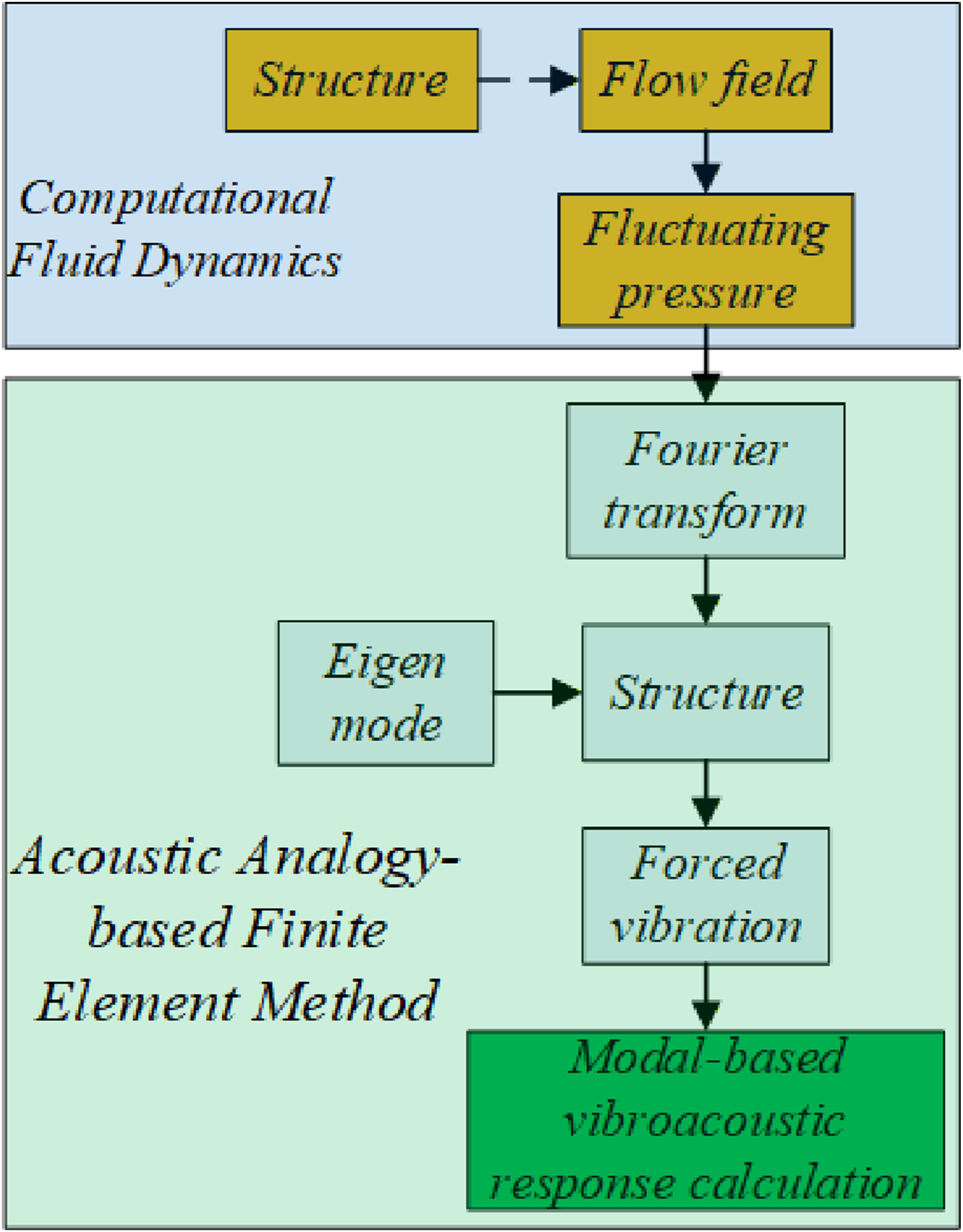
2.1. Flow-field computation
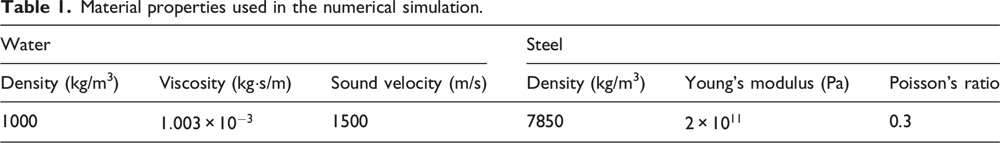
The complete geometrical data of the heat exchanger model are shown in Figure 2. The computational model comprises three parts: the solid structure, the tube-side fluid domain, and the shell-side fluid domain. The solid structure is made of steel, and both fluid domains are filled with water. The material properties are summarized in Table 1. The overall length of the heat exchanger is 1270 mm, and its outer diameter is 230 mm. Both the tube-side and shell-side pipe connections have a nominal diameter of DN80. Inside the shell, 35 tubes are arranged in a square pattern. Each tube has an outer diameter of 20 mm and a wall thickness of 1 mm. The tube pitch is 26 mm, yielding a pitch-to-diameter ratio of 1.3. Three baffles made of poly (vinyl chloride) (PVC) are installed inside the shell to reduce the flow-induced noise generated by the baffles themselves (Ciappi et al., 2012; Prajapati et al., 2023; Zuo and Zhang, 2025), thereby avoiding interference with the analysis. Schematic of the heat exchanger geometry and computational domains. Material properties used in the numerical simulation.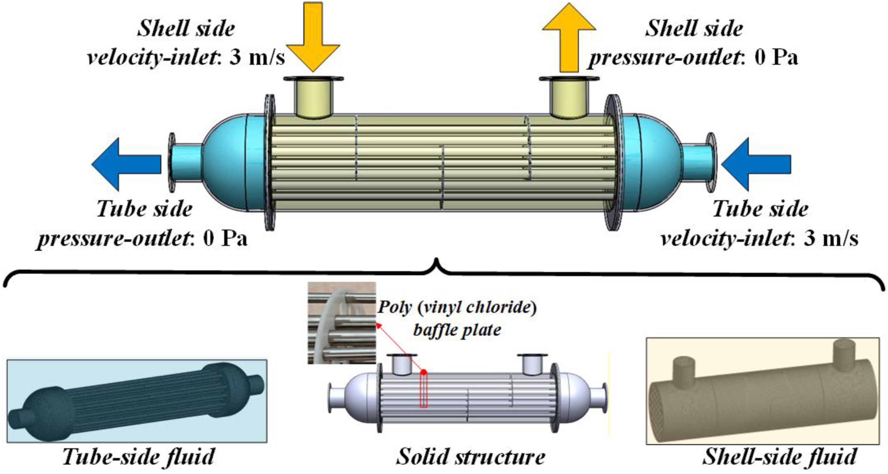
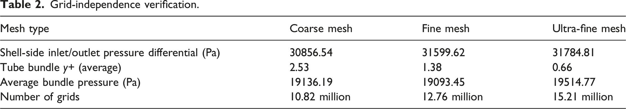
Grid-independence verification.
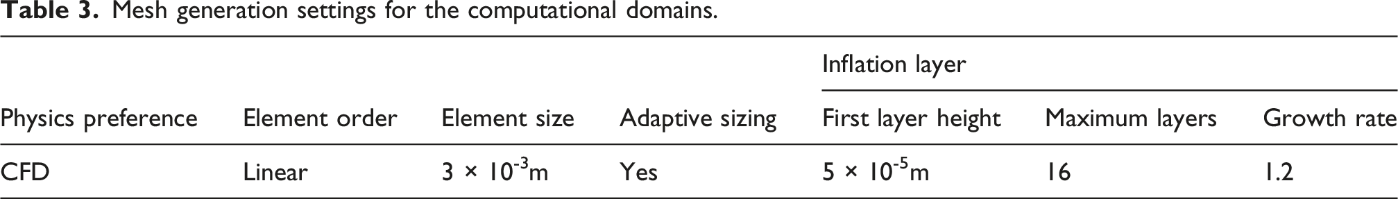
Mesh generation settings for the computational domains.
Numerical setup for the Fluent solver.
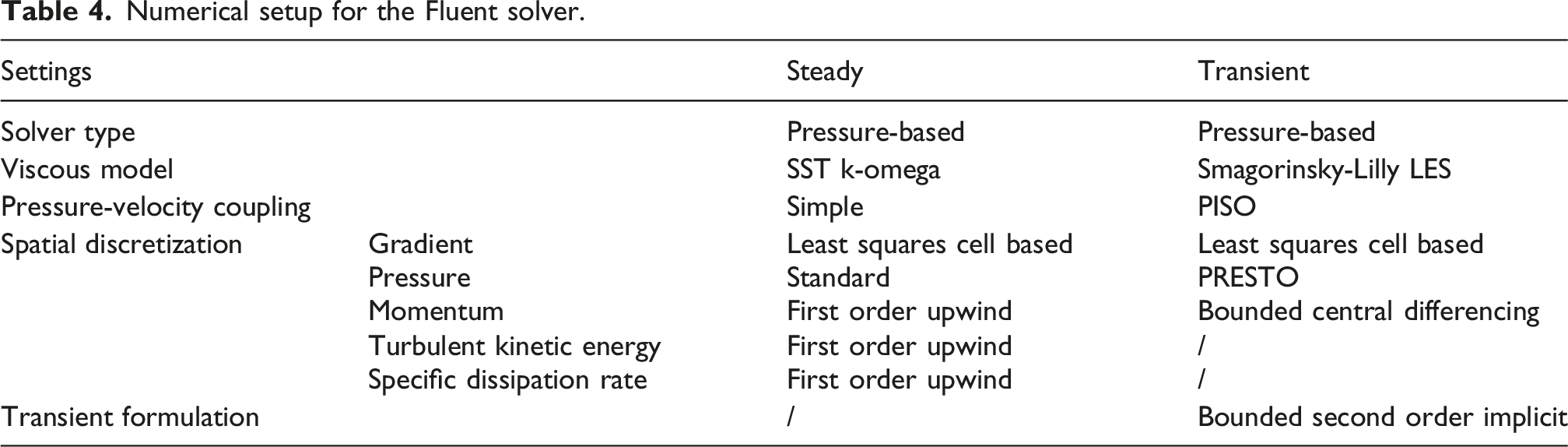
Figure 3 compares the computed velocity field contours and the pulsating pressure contours of the tube-side and shell-side domains. It is evident that, compared with the tube-side flow, the shell-side flow is more unstable and exhibits locally higher velocities, reaching up to 6 m/s. Furthermore, the amplitude of the pulsating pressure in the shell-side flow field (maximum value: 48877.7 Pa) is significantly higher than that in the tube-side flow field (maximum value: 18086.6 Pa). Comparison of velocity and pulsating pressure fields. (a) Tube-side velocity. (b) Shell-side velocity. (c) Tube-side pulsating pressure. (d) Shell-side pulsating pressure.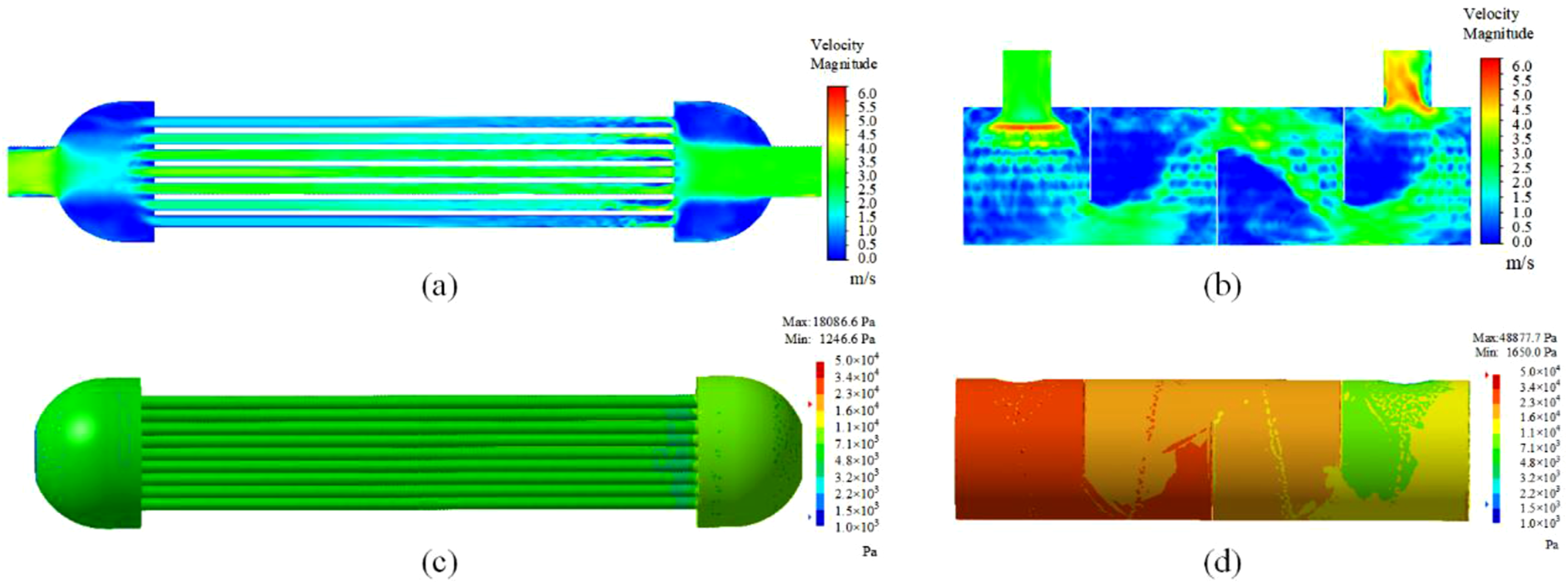
2.2. Acoustic calculations
Acoustic calculations were performed using the transient flow-field results. Figure 4 presents the noise levels at the tube-side and shell-side inlet and outlet of the heat exchanger under shell-side flow conditions. Overall, the acoustic energy is concentrated in the low-frequency range, while the sound pressure level gradually decreases as frequency increases. Furthermore, the noise levels at the tube-side inlet and outlet are approximately 5 dB higher than those at the shell-side inlet and outlet. Because the tube side connects directly to the cooling water circuit, its noise contributes more prominently to the acoustic radiation of that circuit. Sound pressure levels at the inlet and outlet ports under shell-side flow conditions. (a) Tube-side inlet/outlet noise. (b) Shell-side inlet/outlet noise.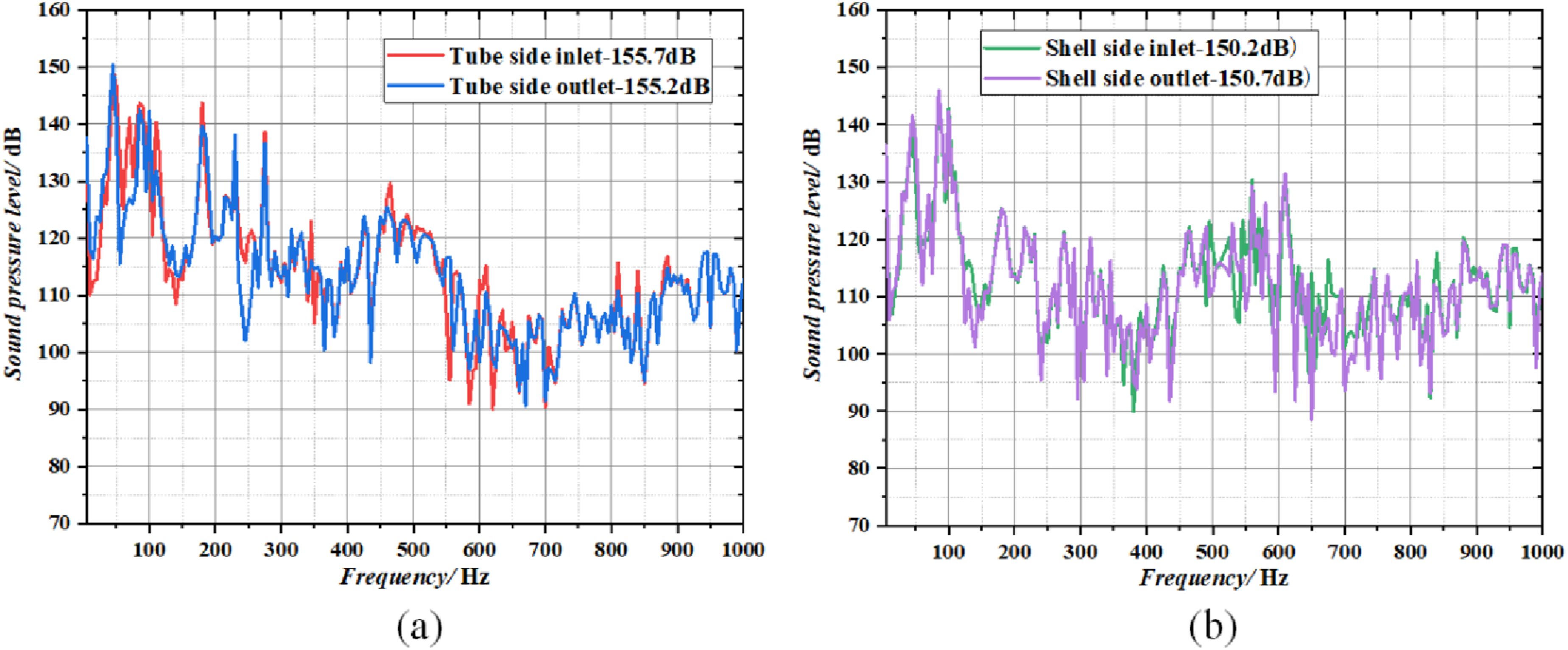
To evaluate the contributions of structural vibrations at various locations within the heat exchanger to noise generation, the exchanger was divided into multiple structural panels, as illustrated in Figure 5. Under shell-side flow conditions, acoustic radiation induced by the structural vibration of each panel was computed based on the pulsating pressure acting on the wall surface obtained from the CFD simulations. Subsequently, the noise contributions from the different panels were compared to identify the primary acoustic radiation sources. Schematic of the heat exchanger structural panels.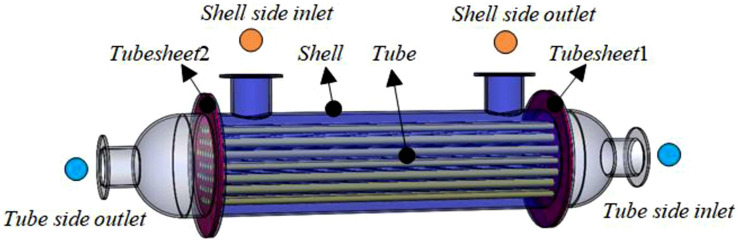
Figure 6 presents a color-mapped comparison of the noise contributions of the structural panels of the heat exchanger under shell-side flow conditions. Here, three structural panel types are considered: tube, tubesheet, and shell. In the figures, color intensity represents the noise contribution level, while “Total” denotes the overall noise contribution. Notably, the color distribution of the tube panel closely matches that of the Total distribution. This correspondence indicates that the tubes dominate noise generation at both the shell-side and tube-side inlet and outlet. Meanwhile, the color patterns of the other panels exhibit weaker agreement with the Total distribution. In some frequency bands, individual panels even appear darker than the Total color. This finding suggests that, within those frequency ranges, these panels suppress noise generation because their vibration occurs in an opposite phase. Noise contributions from different structural panels measured at inlet and outlet under shell-side flow conditions. (a) Tube-side inlet. (b) Tube-side outlet. (c) Shell-side inlet. (d) Shell-side outlet.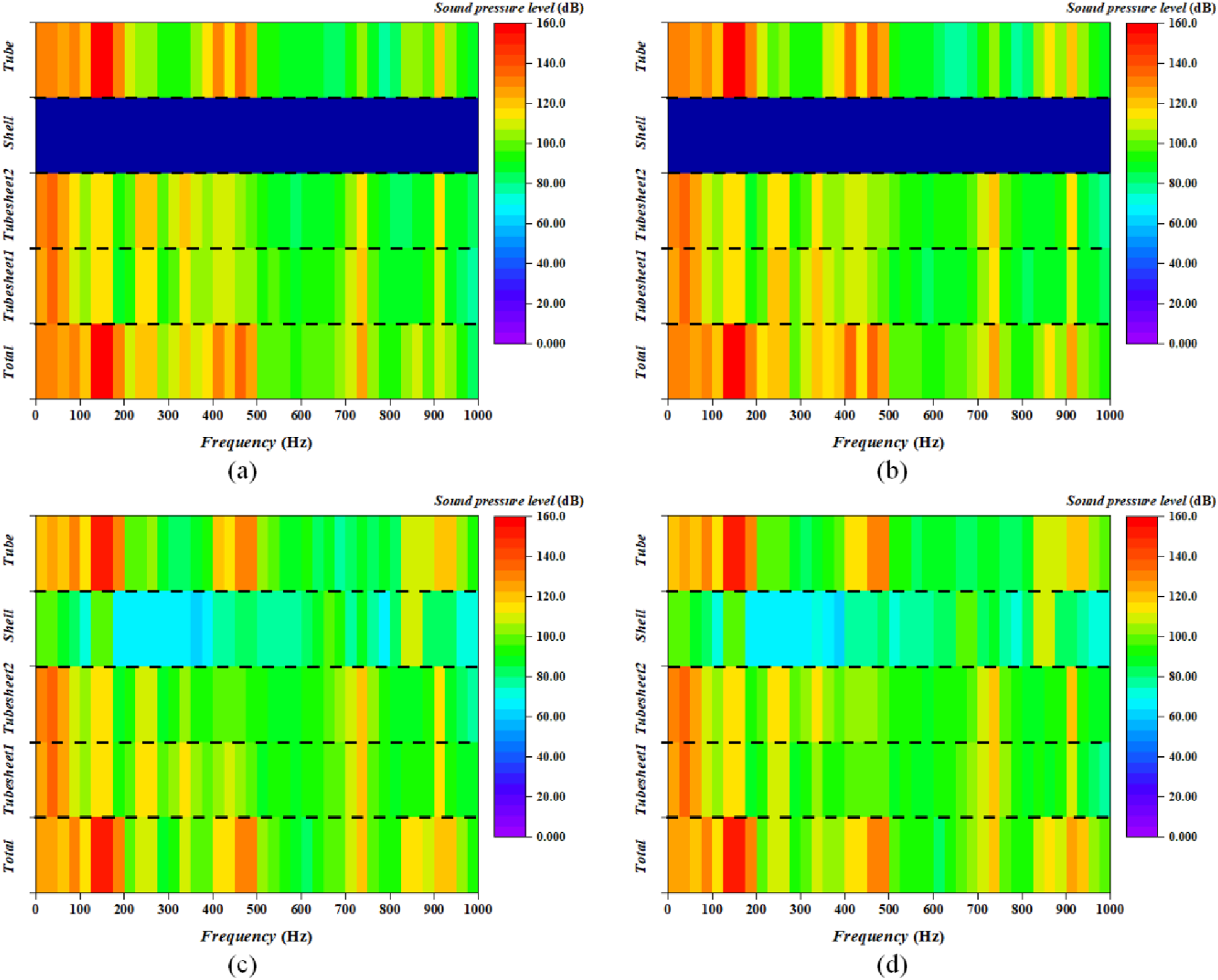
To quantitatively compare noise contributions from different structural panels, a vector projection method was employed to determine the contribution magnitude of each panel. Specifically, the contribution vector of each panel was projected onto the direction of the total vector. When the projection direction aligned with the total vector, the contribution was deemed positive; otherwise, it was considered negative. The projection length therefore represented the effective contribution magnitude. Overall, the projection length of a structural panel onto the total vector was calculated using the following expression: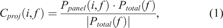
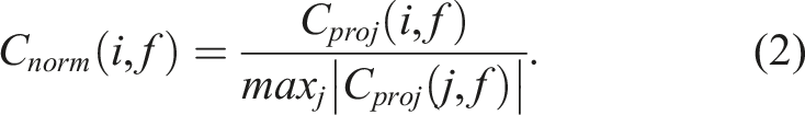
Using the normalized panel contribution method described above, the contributions of each structural panel were analyzed under shell-side flow conditions. As depicted in Figures 7 and 8, the tube structural panel consistently exhibits higher normalized contribution values than the other structural panels. Furthermore, its normalized contributions remain positive at all noise observation points. This pattern indicates that the heat transfer tube bundle dominates noise generation at both the tube-side and shell-side inlet and outlet, particularly near 150 Hz where the acoustic energy is concentrated. In comparison, the tubesheet contributes only weakly, with a noticeable contribution appearing near 50 Hz. Moreover, the tubesheet contributions at the two observation locations exhibit opposite phases. In contrast, the shell structural panel contributes negligibly and is largely overshadowed by the other structural panels. Normalized noise contributions from structural panels measured at tube-side inlet and outlet under shell-side flow conditions. (a) Tube-side inlet. (b) Tube-side outlet. Normalized noise contributions from structural panels measured at shell-side inlet and outlet under shell-side flow conditions. (a) Shell-side inlet. (b) Shell-side outlet.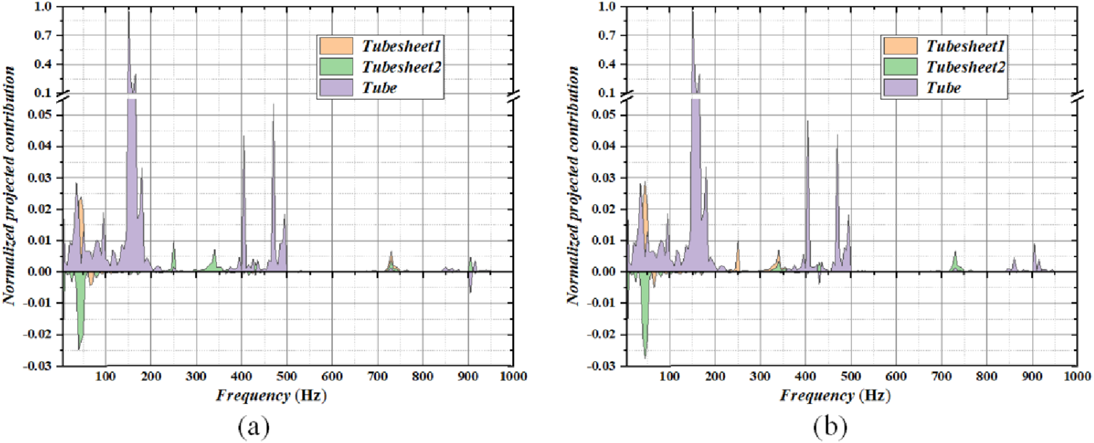
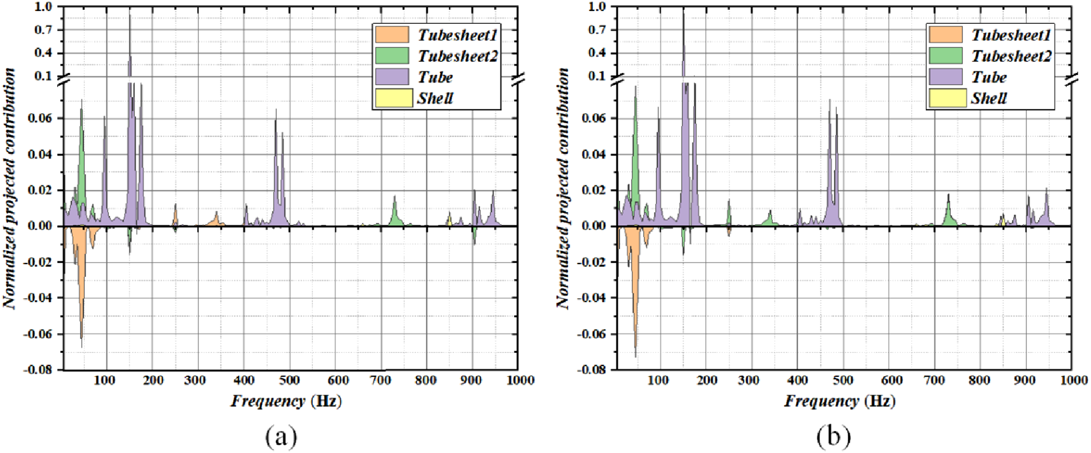
Figure 9 presents the sound pressure levels at the heat exchanger inlet and outlet under tube-side flow conditions. Notably, the tube-side inlet and outlet exhibit higher sound pressure levels, exceeding those at the shell-side inlet and outlet by more than 1 dB. This result indicates that the tube-side inlet and outlet generate the highest noise levels in the heat exchanger regardless of whether the shell-side or tube-side fluid is flowing. Because these locations connect directly to the seawater pipeline, this observation further emphasizes the importance of investigating noise within heat exchangers. Sound pressure levels at each inlet and outlet under tube-side flow conditions. (a) Tube-side inlet/outlet noise. (b) Shell-side inlet/outlet noise.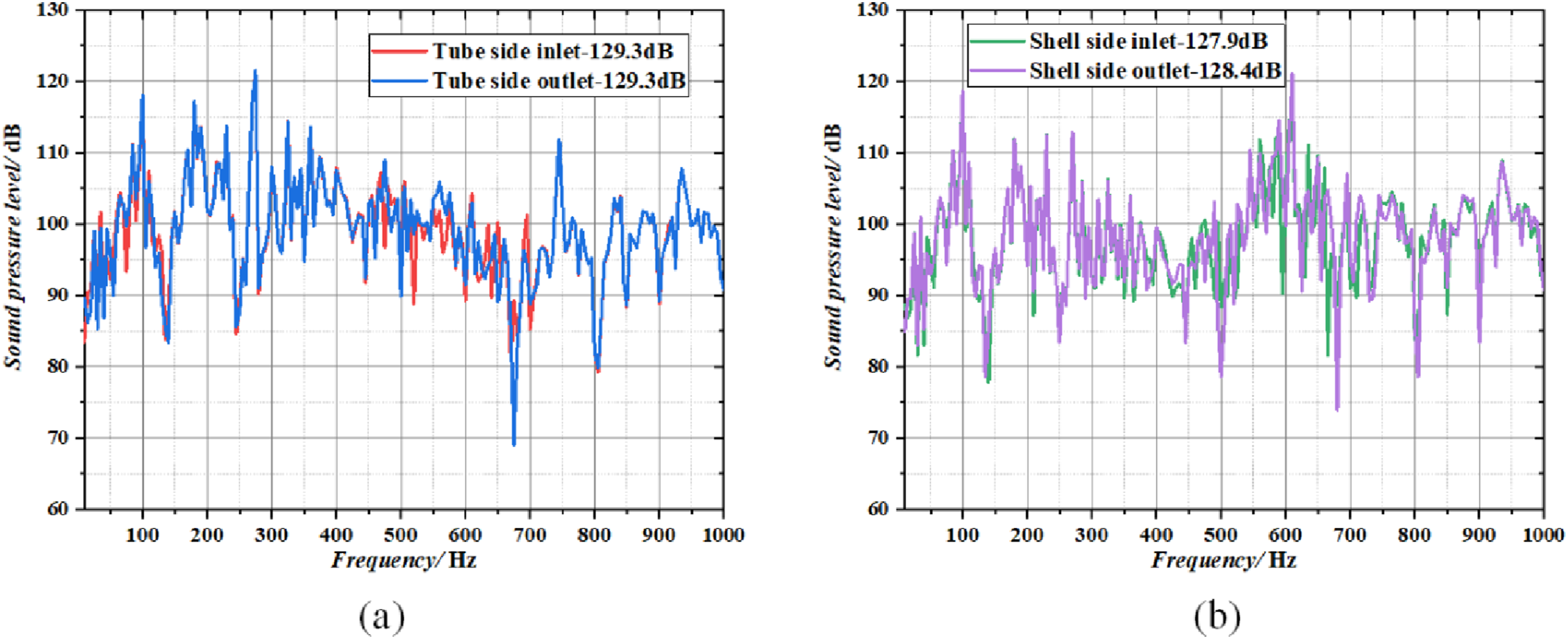
Based on the above analysis, a panel contribution analysis was conducted to compute the noise generated by vibrations in each structural panel and compare their respective contributions. As depicted in Figure 10, the color distribution of the tube panel closely matches the Total distribution, consistent with the shell-side flow condition. This correspondence indicates that vibrations of the heat exchange tubes dominate noise generation at all four inlet and outlet locations under tube-side flow. Noise contributions from different structural panels measured at inlet and outlet under tube-side flow conditions. (a) Tube-side inlet. (b) Tube-side outlet. (c) Shell-side inlet. (d) Shell-side outlet.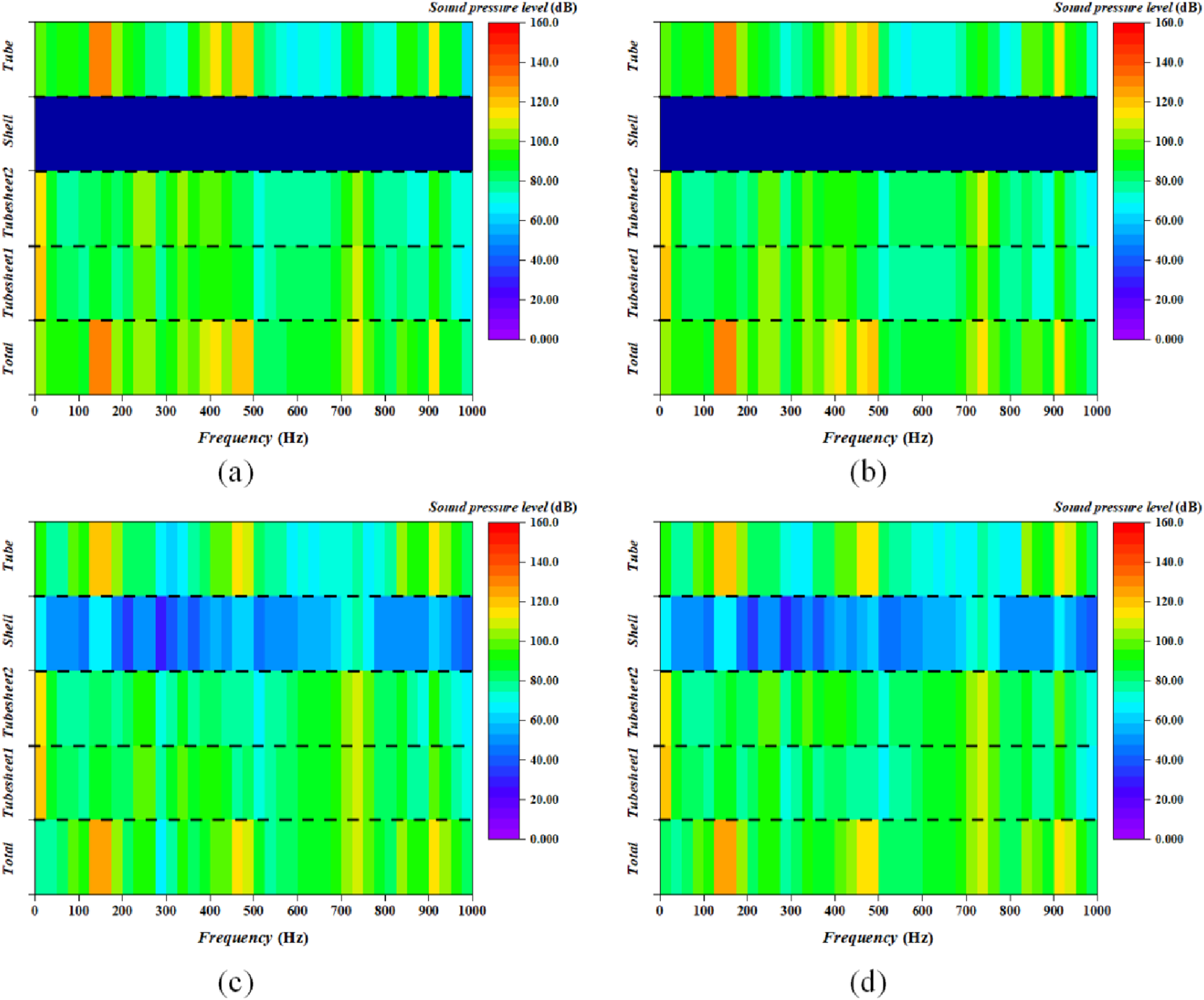
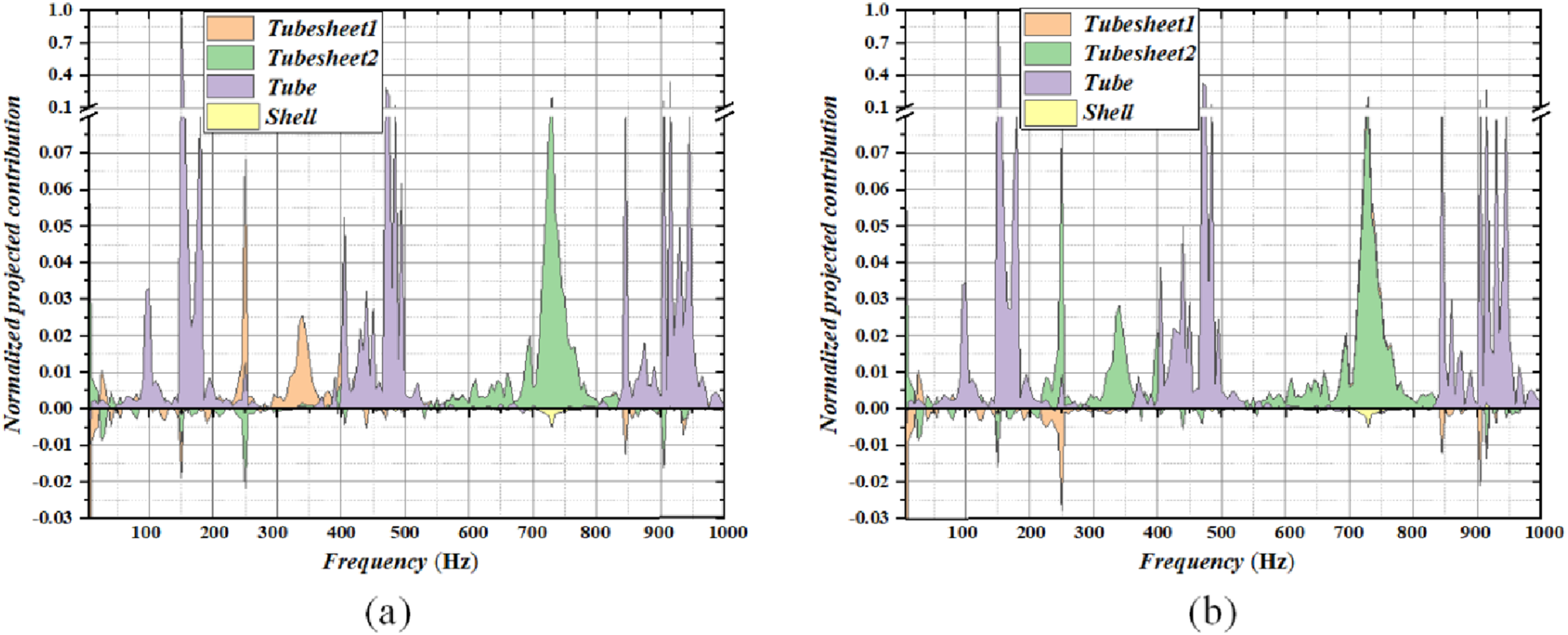
However, unlike the shell-side flow condition, the tubesheet structural panel exhibits notable contributions within the frequency ranges of 230 Hz – 380 Hz and 700 Hz – 800 Hz during tube-side fluid flow, as illustrated in Figures 11 and 12. This behavior results from strong flow impacts at the tubesheet during tube-side fluid flow. Normalized noise contributions from structural panels measured at tube-side inlet and outlet under tube-side flow conditions. (a) Tube-side inlet. (b) Tube-side outlet. Normalized noise contributions from structural panels measured at shell-side inlet and outlet under tube-side flow conditions. (a) Shell-side inlet. (b) Shell-side outlet.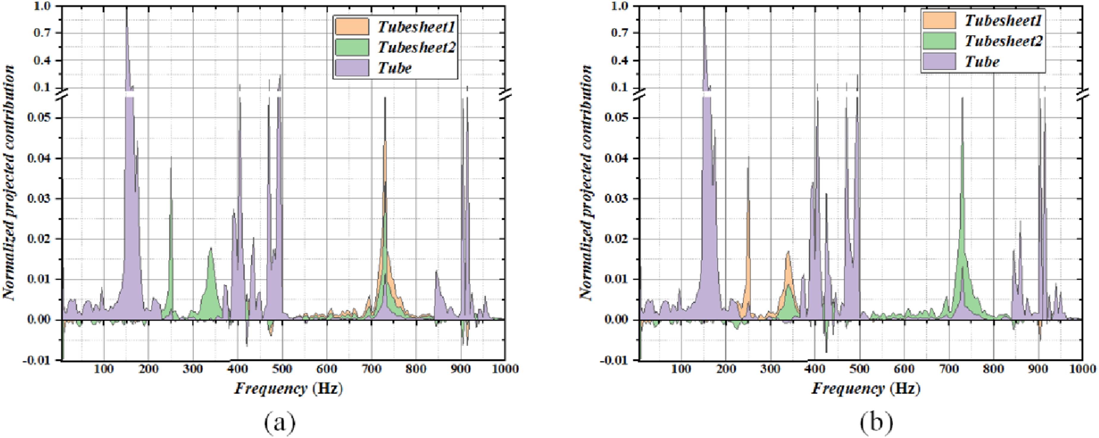
The sound pressure levels at the tube-side and shell-side outlets were compared under both shell-side and tube-side flow conditions. As depicted in Figure 13, shell-side flow generates considerably higher sound pressure levels than tube-side flow. Quantitatively, the tube-side outlet exhibits a sound pressure increase of approximately 26 dB, whereas the shell-side outlet exhibits a corresponding increase of approximately 22 dB. These results indicate that shell-side fluid flow dominates noise excitation in the heat exchanger. Comparison of noise under shell-side and tube-side flow conditions. (a) Tube-side outlet noise. (b) Shell-side outlet noise.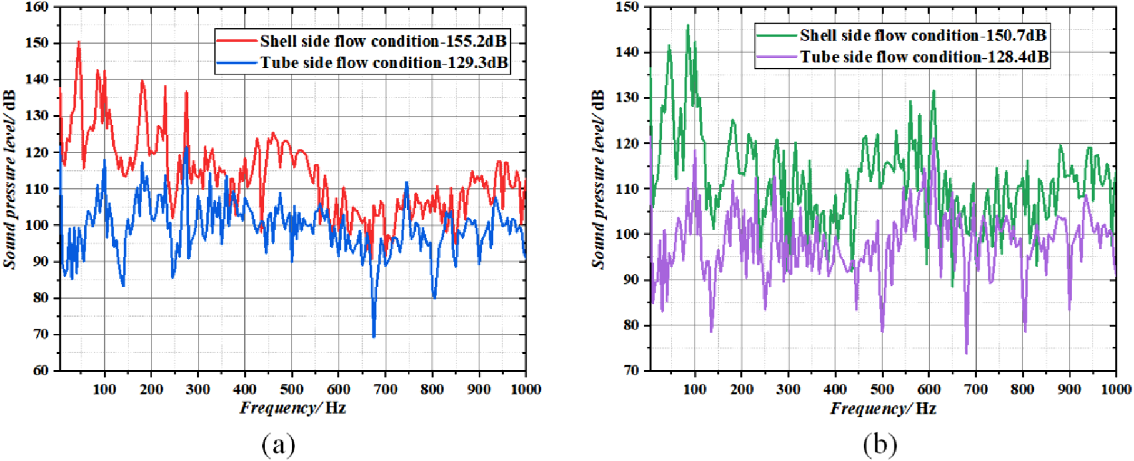
3. Experimental test
The accuracy of the computational results was experimentally validated. Figure 14 illustrates the corresponding test setup. As discussed earlier, shell-side fluid flow primarily generates noise in heat exchangers. Furthermore, the tube-side inlet and outlet exhibit higher noise levels under both shell-side and tube-side flow conditions. Therefore, the validation focused on noise levels measured at the tube-side inlet and outlet during shell-side flow conditions. To eliminate the influence of tube-side flow on hydroacoustic signal measurements, the tube-side flow was stopped, allowing only shell-side fluid to flow at a regulated velocity of 3 m/s. Test setup. (a) Structural schematic of the heat exchanger. (b) Site photo of the experiment.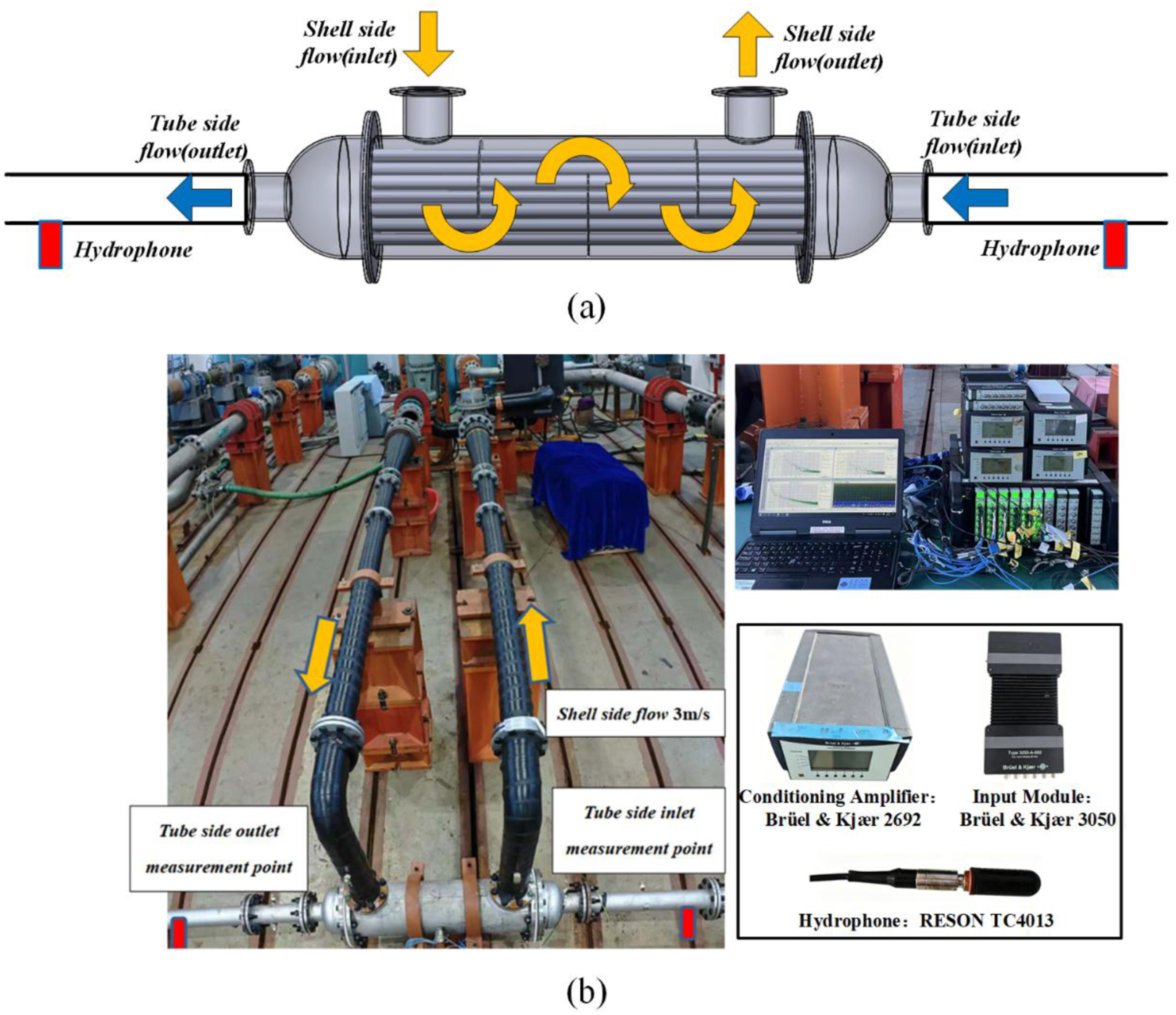
The sound pressure was measured using a RESON TC4013 hydrophone, which has a frequency response of 1 Hz to 170 kHz and a sensitivity of −211 dB ± 3 dB (ref 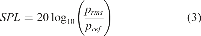
Figure 15 compares the calculated and experimental noise levels at the tube-side inlet and outlet under shell-side flow conditions. At the tube-side inlet, the calculated overall sound pressure level (OASPL) is 155.7 dB, while the experimental value is 160.4 dB, yielding a difference of 4.7 dB. At the tube-side outlet, the calculated OASPL is 155.2 dB and the experimental value is 160.2 dB, giving a difference of 5.0 dB. Several factors may contribute to the discrepancies between the computed and experimental noise levels observed in Figure 15. First, although vibration and noise control measures were applied to the shell-side pump, they could not be completely eliminated. Residual pump noise transmitted through the shell-side fluid and structure inevitably coupled into the tube-side circuit, thereby elevating the measured noise levels at the tube-side inlet and outlet. Second, acoustic reflections occurred in the piping system connected to the tube side. These reflections can interfere with the direct acoustic signal and produce constructive or destructive effects at specific frequencies, leading to deviations between the measured and predicted spectra. Third, suboptimal welding quality has resulted in partial obstructions at the flange connections, which affect sound transmission and consequently introduce uncertainties into the experimental results. Comparison of experimental and computational noise levels. (a) Tube-side inlet. (b) Tube-side outlet.
Despite these discrepancies, the overall spectral trends show good agreement between the computation and the experiment, and the differences in the total sound pressure level are within 5.0 dB. Therefore, the comparison confirms the accuracy of the computational results for engineering purposes.
4. Conclusion
In this study, we performed a computational analysis of flow-induced noise in heat exchangers. Consequently, the primary noise excitation mechanisms were identified, and the dominant noise-contributing components were clarified. The following main conclusions were derived: (1) Internal fluid flow within the heat exchanger generates substantial noise at the tube-side inlet and outlet connected to the seawater pipeline. The resulting noise propagates along the piping and degrades acoustic stealth performance, emphasizing the importance of investigating flow-induced noise in heat exchangers. (2) Compared with tube-side flow, shell-side flow produces substantially higher sound pressure levels, with increases of approximately 26 dB at the tube-side outlet and 22 dB at the shell-side outlet. These results indicate that shell-side fluid flow constitutes the primary noise excitation source in the heat exchanger. (3) A normalized panel contribution calculation method based on vector projection was established to compare the noise contributions of different structural panels within the heat exchanger at the inlet and outlet. This analysis revealed that heat exchanger noise is primarily generated by tube vibrations.
Overall, these findings provide valuable guidance for the acoustic evaluation and low-noise design of heat exchangers. Nevertheless, the baffles are made of PVC, which produce negligible flow-induced noise; therefore, they were excluded from the panel contribution analysis. Future work should incorporate baffle-induced noise, particularly for metallic baffles. Moreover, the absence of a systematic parametric analysis restricts the generalizability of the present results to heat exchangers with substantially different structural configurations. Experimentally, future test setups should be better designed to isolate shell-side noise sources (e.g., pump noise), and an anechoic termination should be used on the tube side to approximate a non-reflecting boundary.
Footnotes
CRediT authorship contribution statement
Funding
The authors disclosed receipt of the following financial support for the research, authorship, and/or publication of this article: This research was supported by the National Key Laboratory on Ship Vibration and Noise under Grant No. WDZC70202020102.
Declaration of conflicting interests
The authors declared no potential conflicts of interest with respect to the research, authorship, and/or publication of this article.
Data Availability Statement
Data will be made available on request.