






Abstract
To address the technical bottleneck where high-precision modeling and efficient solution are mutually restrictive in the analysis of vehicle non-stationary random vibration, this study proposes an innovative analytical method integrating the finite element method (FEM), transient power spectral density (PSD) method, and spatial-domain pseudo-excitation method (PEM). The core principles of the transient PSD method are systematically elaborated, the relevant theoretical formulas of the spatial-domain PEM are derived, and the specific solution procedure for the vehicle FEM under non-stationary conditions is clarified. Taking a 7-degree-of-freedom (DOF) vehicle spatial model as the validation object, comparative simulation verification is conducted between the proposed method and the Monte Carlo method. The results show that the simulation curves of the two methods are in high agreement with a maximum error of only 5.32%, verifying the validity of the proposed method; meanwhile, the simulation time of the proposed method is reduced by 90.36% compared with the Monte Carlo method, which significantly improves the solution efficiency. On this basis, a complex FEM of the whole vehicle is established, and the time-frequency PSD and RMS value of vibration at the seat position under non-stationary conditions are successfully solved. In summary, the proposed method can simultaneously balance modeling accuracy and solution efficiency, providing an efficient and reliable technical support for the analysis of vehicle non-stationary random vibration and possessing favorable engineering application value.
1. Introduction
Road excitation is the main excitation source of vehicles, which reflects the combined effect of road roughness and vehicle speed (Wang et al., 2024; ISO 2631-1, 1997). Road excitation is a function of time and has the characteristics of stochastic process. When the vehicle runs at a constant speed, the road excitation is a stationary stochastic process, and the vehicle vibration response is stationary. When the vehicle runs at non-uniform speed, the road excitation is a non-stationary stochastic process, and the vehicle vibration response is non-stationary.
At present, most studies on vehicle ride comfort focus on constant-speed driving conditions. However, when a vehicle travels on urban roads, its actual operating states are often non-uniform, such as starting, accelerating, and braking. In such cases, the road excitation in the time domain is non-stationary. Therefore, conducting research on ride comfort under non-stationary conditions is more consistent with the actual driving situation. Nevertheless, the non-stationary random vibration theory is far less mature and widely applied than the stationary random vibration theory, and there are relatively few studies on vehicle random vibration under non-stationary conditions.
Research on vehicle ride comfort under non-stationary conditions mainly involves two aspects: modeling and solution. At present, the lumped parameter method is the primary modeling approach for non-stationary conditions (Hammond and Harrison, 1981; Harrison and Hammond, 1986; Jin, 1993; Liu et al., 1997, 2023; Zhao and Gang, 1996). This method features a simple model structure, a small number of parameters and low computational cost. However, it has obvious drawbacks, including low modeling accuracy, a narrow scope of application and great difficulty in constructing complex models. To address the deficiency of low modeling accuracy in the lumped parameter method, FEM is adopted in this paper to build a complex vehicle model. Currently, FEM has been applied in the research on vehicle ride comfort under stationary conditions (Eriksson and Friberg, 2000; Tian et al., 2012; Wang et al., 2023). FEM boasts high modeling accuracy and a wide scope of application, which can be used for vibration analysis, collision analysis, fatigue life analysis and other research fields. Although the modeling and solution process are time-consuming, such shortcomings can be overcome with the improvement of computer performance and the adoption of efficient solution methods. Meanwhile, some scholars have successively proposed novel dynamic modeling methods such as adaptive measurement-based substructure identification and neural network-integrated hybrid modeling, providing new technical approaches for the high-precision modeling and parameter identification of complex vehicle dynamic systems (Yang et al., 2025; Zhou et al., 2024).
The primary solution method for investigating vehicle ride comfort under non-stationary conditions is the covariance equivalence method (Akpan and Kujath, 1995; Luo and Jin, 2013; Luo and Wei, 1990; Raju and Narayanan, 1991; Zhang and Zhang, 2005). Based on the covariance equivalence theory, this method constructs non-stationary road excitation and then solves for vibration responses in the time domain. It is not only the mainstream approach for researching vehicle non-stationary random vibration, but also a core method in the field of random vibration control. As a time-domain solution method, the covariance equivalence method can only be used to solve for vehicle vibration responses, and is not applicable to calculating the PSD and RMS value of vehicle non-stationary random vibration. Meanwhile, some scholars have adopted a series of new methods to investigate vehicle ride comfort under nonstationary conditions. Li et al. built a two-DOF single wheel model and proposed a method for solving the statistical characteristics of vehicle non-stationary random vibration via spatial frequency Fourier transform (Li et al., 2021). Wang et al. established a classical 1/4 vehicle model and presented a new technique for non-stationary random vibration analysis of vehicles, which is based on the PEM and the precise integration method (Wang et al., 2025). Zhang et al. (2025) developed a 7-DOF vehicle model and proposed a new method that adopts the evolutionary PSD to address the nonstationary vibration problem of vehicles. Zhang et al. (2003) derived the transient spatial frequency response function and transient spatial PSD from the time-frequency response function, and verified the obtained results. These methods are only applicable to simple models established by the lumped parameter method.
In summary, the existing research on vehicle non-stationary random vibration mainly has the following two problems: there are mainly the following three problems: (1) The establishment of vehicle vibration model is still limited to the lumped parameter method. The disadvantage is that the vehicle specific structure cannot be considered, the model accuracy is low, and it is only suitable for simple models; (2) The covariance equivalence method can only solve for the time-domain vibration responses of vehicles and is unable to calculate the statistical characteristics such as the PSD and RMS value of vehicle non-stationary random vibration.
The research objective of this paper is to investigate the solution to the ride comfort problem of complex vehicle models under non-stationary random road excitation. The innovations of this paper are reflected in two aspects: first, the introduction of a high-precision FEM into the research on vehicle non-stationary dynamics; second, the proposal of an efficient solution method using the transient PSD method and the spatial PEM. PEM is an innovative theory for structural random vibration analysis proposed by Lin and Zhang (2004). It has now been widely applied in fields such as seismic engineering of long-span structures (Jia et al., 2013; Lin et al., 1994; Zhang et al., 2013), railway engineering (Han et al., 2025; Wu et al., 2023; Yang et al., 2023), and wind-induced vibration engineering (Tian et al., 2024, 2025; Zhu et al., 2024), yet its application in the automotive engineering field remains limited (Li et al., 2010, 2016; Wang et al., 2020; Zhang et al., 2006). Existing research on the PEM in automotive engineering has mostly focused on the analysis of stationary random vibration.
The structure of this article is as follows: in Section 2, the transient PSD method is summarized. The spatial domain PEM is derived and realized in the general finite element software in Section 3. In Section 4, detailed steps for simulating the vehicle ride comfort under non-stationary conditions are proposed. Verification is implemented on the basis of a simple 7-DOF space model in Section 5. In Section 6, a full-vehicle FEM is established, and ride comfort simulation analysis under non-stationary conditions is carried out. In the last section, some conclusions are drawn.
2. Transient PSD method
Under non-stationary conditions, in time domain, the road excitation is non-stationary, the vehicle system differential equation is time-invariant, and the response is non-stationary; on the contrary, in spatial domain, the road excitation is stationary, the vehicle system differential equation is time-varying, and the response is non-stationary. The frequency response function
The expressions of road roughness in time domain and spatial domain are (Mickey, 2019)


By comparison, it can be obtained


Equation (4) is brought in

3. Spatial PEM
3.1. The fundamental theory of time domain PEM
The basic formula of the time domain PEM is as follows (Wang et al., 2023)




3.2. The fundamental theory of spatial domain PEM
According to the basic idea of the time domain PEM, the spatial domain PEM is derived.

The pseudo response

Subsequently, the spatial domain response PSD may be written as

3.3. The fundamental theory of multi-point excitation PEM in spatial domain
In the spatial domain, regardless of whether a vehicle is traveling at a constant speed or a non-uniform speed, the road excitation is a stationary stochastic process. Consider a linear structural system subjected to multi-point partially coherent stationary random excitations, and let its PSD matrix be denoted as

Construct r pseudo excitation vectors

According to equation (11), there is

Then

3.4. Realization of spatial domain PEM in finite element software
PEM can convert the stationary stochastic process into the harmonic stochastic process (Zhao et al., 2016). In the process of non-uniform driving, the vibration of the vehicle at a certain moment may be seen as a stationary stochastic process. In spatial domain, the road excitation is a stationary stochastic process. Therefore, the spatial domain PEM can finish the ride comfort analysis of the vehicle FEM by means of the harmonic analysis, which is easy to implement in general finite element software.
By Euler formula

Bringing equation (17) into equation (14), it can get

The


According to equation (16), the transient response PSD may be written as

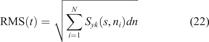
Therefore, as long as the amplitude of the response is obtained by means of harmonic response module, the transient response PSD and RMS may be achieved according to equations (21) and (22).
4. Detail steps to solve the vehicle FEM under non-stationary conditions
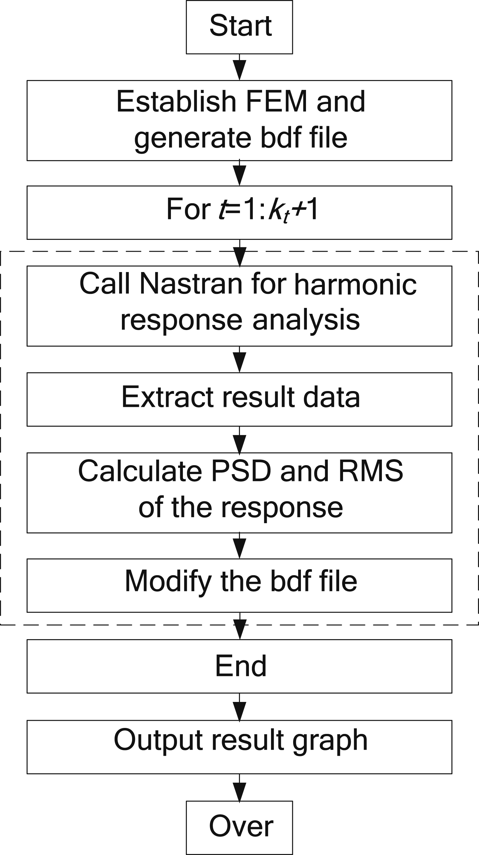
Under non-stationary conditions, the specific steps of vehicle ride comfort simulation are shown in Figure 1. The detail steps are (1) Build the vehicle FEM, set up the boundary conditions, and generate the bdf file; (2) Cycle with time t; (3) Automatically call Nastran program, run the bdf file, and perform harmonic vibration analysis; (4) Extract the displacement result data of the relevant nodes, calculate the response amplitude, and calculate the transient response PSD and RMS according to equations (21) and (22); (5) Based on the calculation formulas (6) When t = k
t
+ 1, the loop ends; (7) Output the result graph. Flow chart.
5. Verification
The traditional method for researching vehicle ride comfort under non-stationary conditions involves modeling with the lumped parameter method and solving with the covariance equivalence method. This method suffers from low modeling accuracy, a narrow scope of application and difficulty in establishing complex models. Meanwhile, it can only yield time-domain response quantities varying with time, and cannot directly obtain the PSD and RMS value.
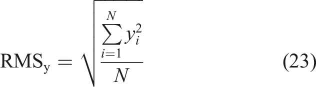
To verify the effectiveness and efficiency of the method proposed in this paper, a Monte Carlo method is adopted on the basis of the traditional method to calculate the RMS values of response quantities for comparison and verification. The RMS values of response quantities are obtained according to equation (23).
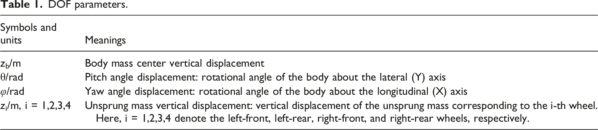
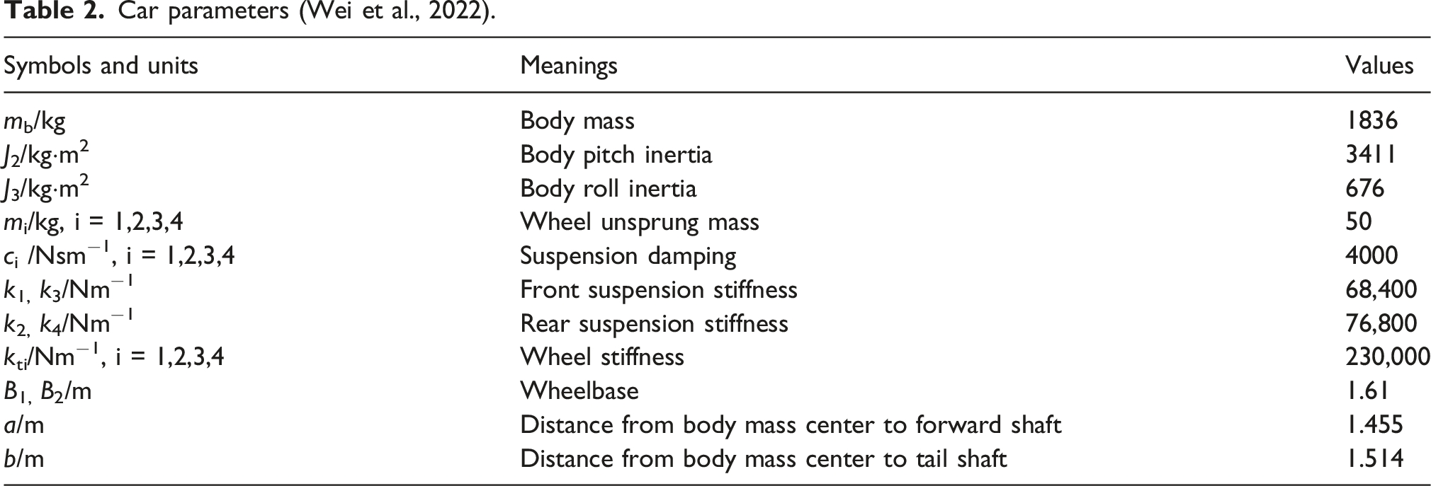
The verified model is a 7-DOF spatial car model as the research object, as shown in Figure 2. The DOF parameters and the car parameters of the model are shown in Tables 1 and 2, respectively. The simulation is carried out on Class A road surface (ISO 8608, 2016), starting from 0 m/s with a constant acceleration of 2 m/s2 for a duration of 15 s, which constitutes a typical working condition matching the average acceleration of vehicle 0–100 km/h acceleration. Car mechanical model. DOF parameters. Car parameters (Wei et al., 2022).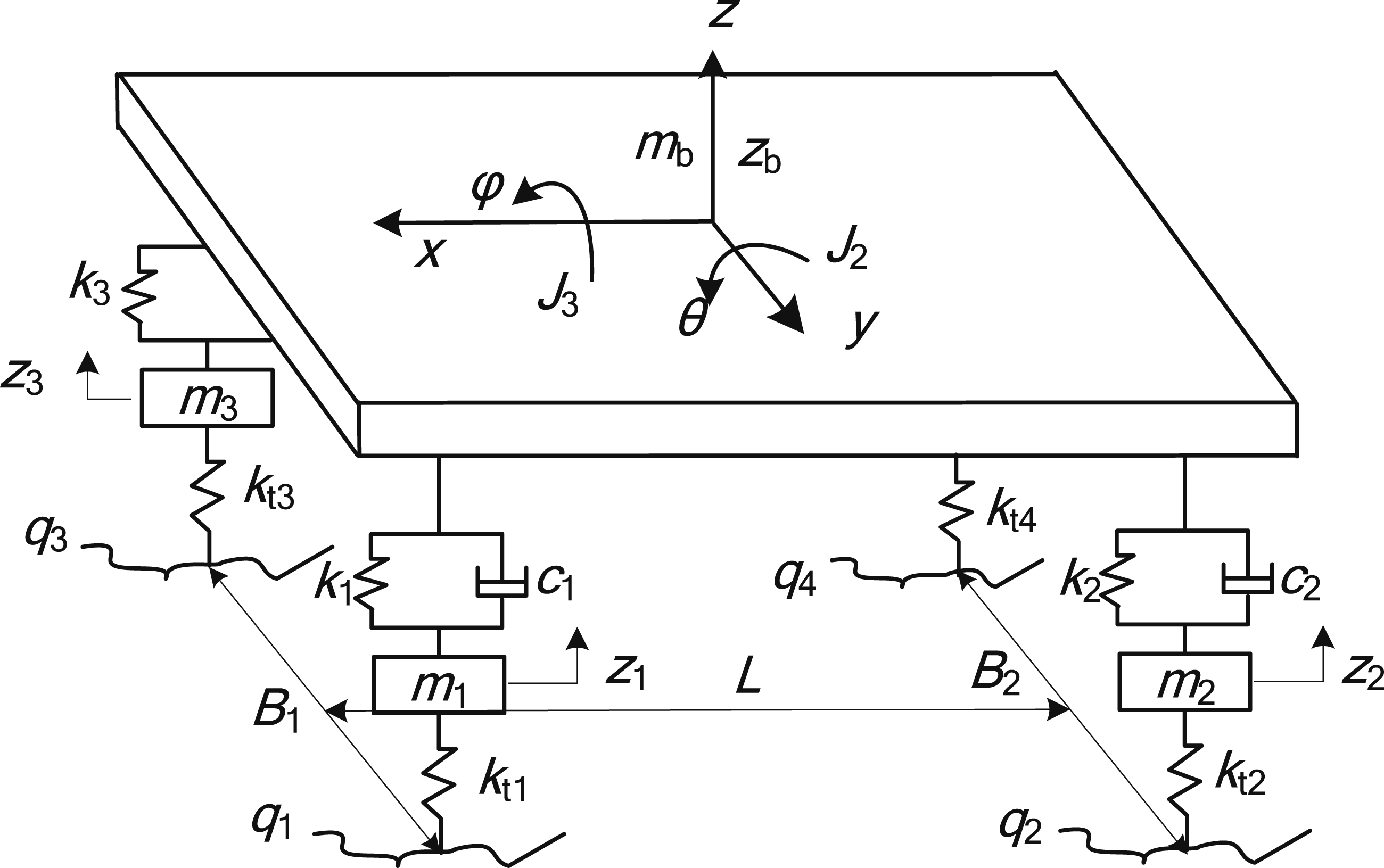
Establish the car FEM. In HyperMesh, the car FEM is built according to Figure 2 and Table 2, which is shown in Figure 3. The suspension element uses PBUSH, the tire element uses PELAS, the concentrated mass element uses CONM2, and the body element uses CBEAM with a box cross-section. Since a 7-DOF rigid-body model is used in this study, the body is assigned a high elastic modulus of 9 × 10¹⁴ Pa to simulate its rigid-body behavior. Car FEM.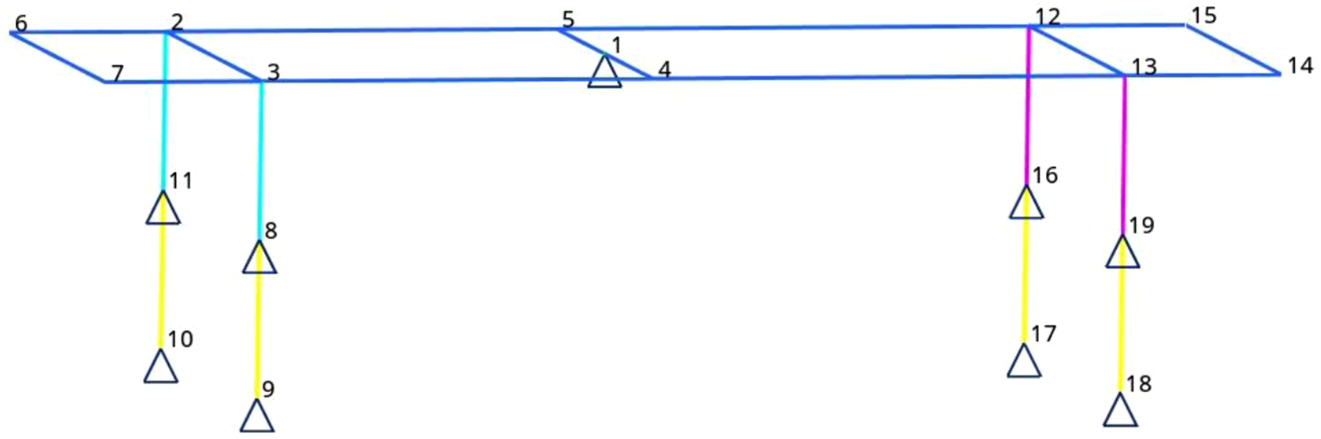
The spatial domain PSD of road excitation is written as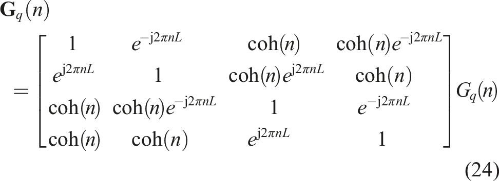


According to equation (13), the nonzero eigenvalues and eigenvectors of 



The pseudo excitation in the spatial domain is written as
After the FEM is established, the program is compiled in Matlab software according to the program flowchart in Figure 1. The response variables are the body mass center acceleration
The pseudo responses are written as








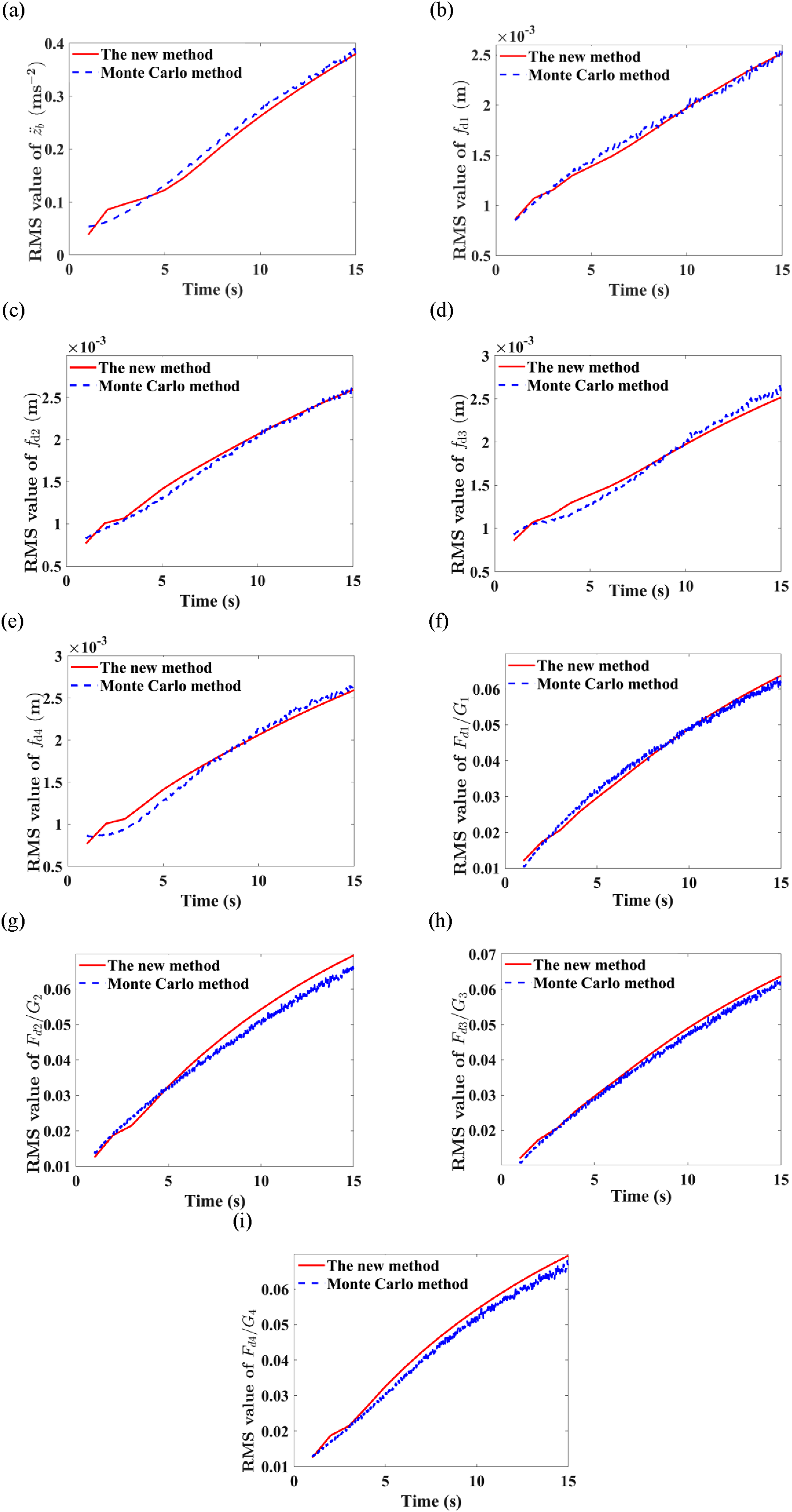
At a certain time, according to equations (32) to (40), the response amplitude is calculated, and the total transient spatial PSD of the response is obtained through equation (21). Figure 4 is the spatial PSDs of the responses. In order to facilitate the comparison of the two methods, the RMS values of the responses are compared and displayed in Figure 5. Spatial PSDs of the responses. (a) The vehicle body mass center acceleration; (b) The left front suspension dynamic deflection, (c) The left rear suspension dynamic deflection; (d) The right front suspension dynamic deflection; (e) The right rear suspension dynamic deflection; (f) The left front wheel relative dynamic load; (g) The left rear wheel relative dynamic load; (h) The right front wheel relative dynamic load; (i) The right rear wheel relative dynamic load. Comparison of response RMS values.(a) The vehicle body mass center acceleration; (b) The left front suspension dynamic deflection, (c) The left rear suspension dynamic deflection; (d) The right front suspension dynamic deflection; (e) The right rear suspension dynamic deflection; (f) The left front wheel relative dynamic load; (g) The left rear wheel relative dynamic load; (h) The right front wheel relative dynamic load; (i) The right rear wheel relative dynamic load.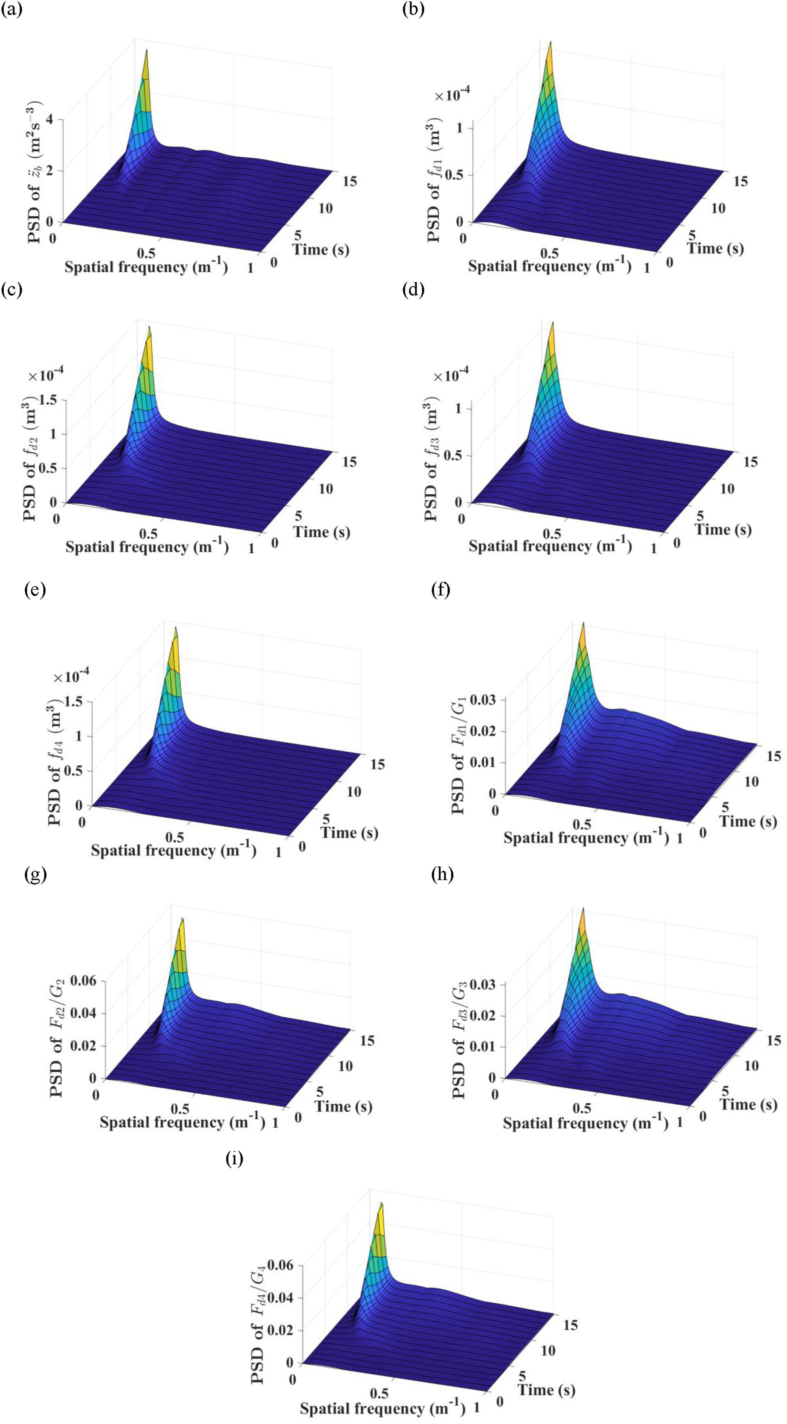
From Figure 4, the non-stationary random vibration responses are correlated not only with time but also with spatial frequency. With the increase of vehicle speed, the PSD of the body centroid acceleration, suspension dynamic deflection and wheel relative dynamic load all show an increasing trend. The PSD of each response quantity reaches the maximum value at the spatial frequency of n = 0.06 m−1 and time t = 15 s. An extreme value appears in the vehicle speed centroid acceleration and the relative dynamic load of each wheel at the spatial frequency of n = 0.31 m−1 and time t = 15 s.
From Figure 5, the RMS of each response quantity increases with the rise of vehicle speed. The RMS curves obtained by the proposed method and the Monte Carlo method are almost identical in shape, among which the RMS error of the left rear wheel dynamic deflection is the largest with a maximum relative error of 5.32%, which verifies the effectiveness of the proposed method. The running time of the proposed method is 239 s, while that of the Monte Carlo method is 2480 seconds with the sample size N = 5000. The running time of the proposed method is reduced by 90.36%, which demonstrates its high efficiency. From the perspective of the simulation process, the proposed method does not require the derivation of complex mathematical formulas and is mainly implemented through the harmonic response analysis module of finite element software.
6. Complex vehicle model development and simulation
6.1. Establishment of car FEM
The advantage of the lumped parameter method is that it requires fewer parameters and is simple. The disadvantage is that the vehicle specific structure cannot be considered, the model accuracy is low, and it is only suitable for simple models. On the contrary, the advantage of the FEM is that it may not only build a simple model but also build an accurate complex model, and does not require complex formula derivation. Meanwhile, the FEM can take into account the elasticity of the vehicle body, making it more consistent with the actual model.
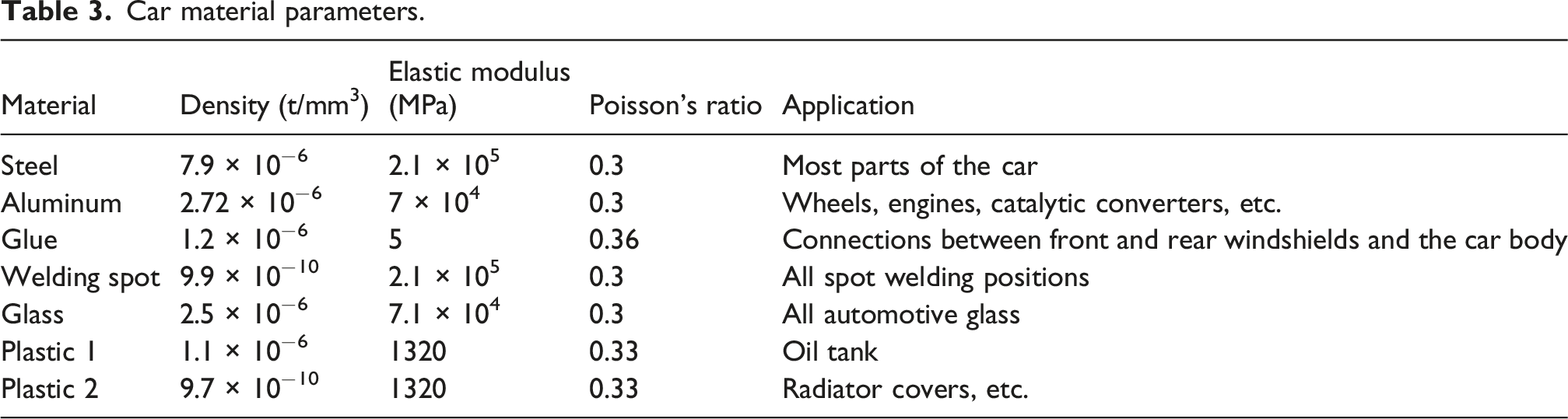
In HyperMesh software, the car three-dimensional model is processed. The detailed steps of building the car FEM are shown in Figure 6. The establishment of a finite element spatial model for a car mainly uses shell elements, solid elements, beam elements, spring-damper elements (CELAS2), concentrated mass elements (CONM2), and spot-welding elements (ACM or RBE2 elements). The material parameters of the car are shown in Table 3. Flow chart. Car material parameters.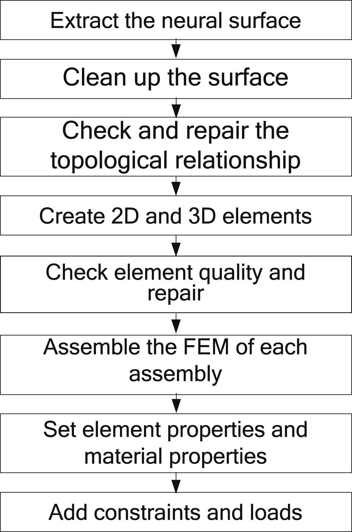
The full-vehicle FEM of a car mainly includes the vehicle body, power system, braking system, front and rear suspension systems, steering system, and tires. In order to facilitate loading, four tires are deleted and then replaced by four spring elements. In Figure 7, the car FEM consists of 1490235 nodes and 1394272 elements. The car FEM. (a) Front view of the car FEM. (b) Bottom view of the car FEM.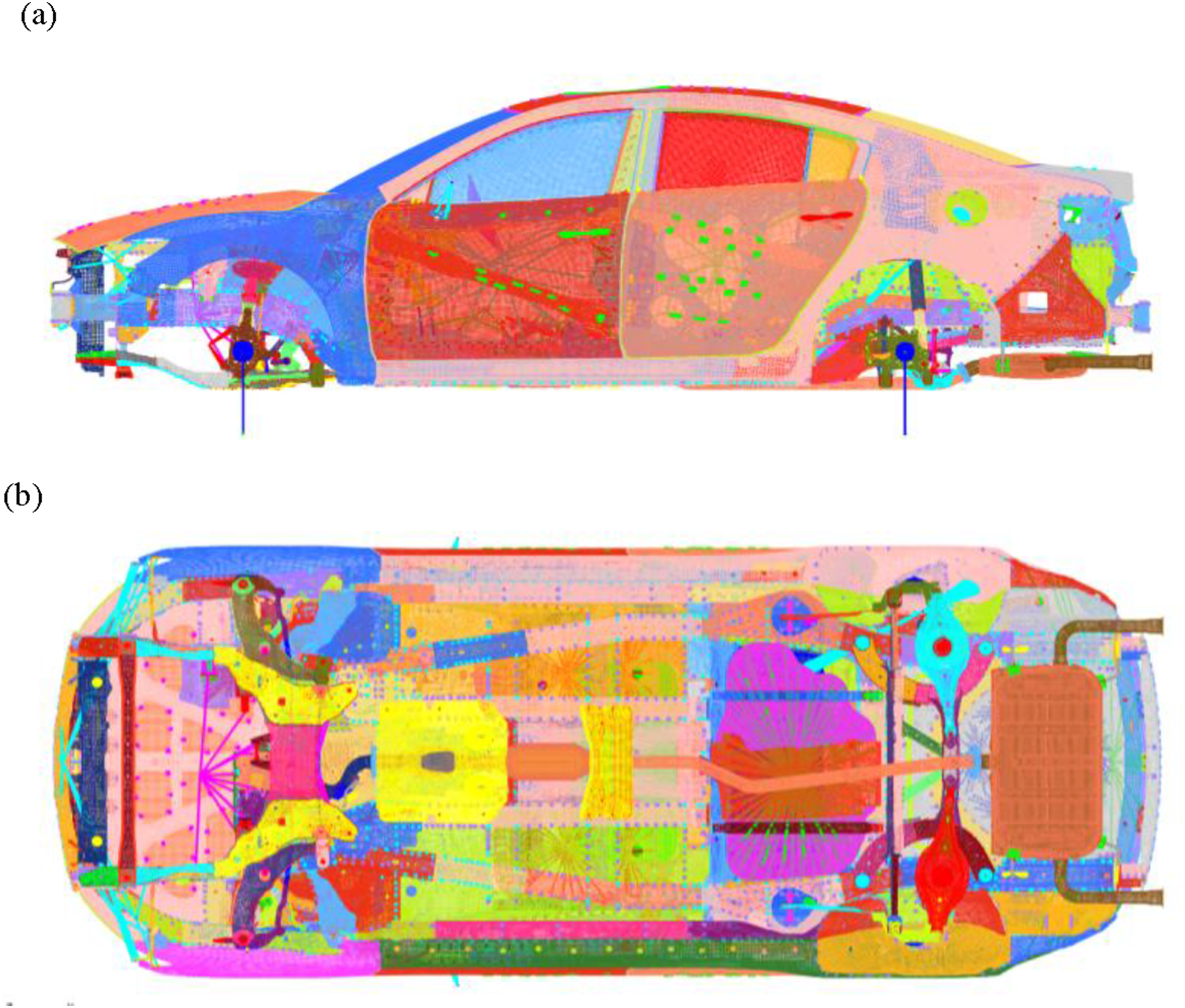
6.2. Simulation
In accordance with the ISO 2631-1 standard, vehicle ride comfort is evaluated by the frequency-weighted RMS acceleration, and its calculation formula is shown in equation (41)
The operating condition is B-class road surface (ISO 8608, 2016), with an initial velocity of 0 m/s, an acceleration of 2 m/s2, and a running time of 15 s. The accelerations of the driver seat position and a passenger seat position are taken as the responses, respectively. According to the flow chart of Figure 1, the program is programmed in Matlab software.
When conducting harmonic response analysis for vehicle ride comfort using the modal method in Nastran, the modal characteristics of the full-vehicle finite element model remain constant under various transient operating conditions. To avoid computational redundancy and efficiency bottlenecks arising from repeated modal solving, the restart analysis technique is adopted in this paper. Meanwhile, considering the research characteristics of vehicle ride comfort, modal order reduction is implemented to retain only the dominant modes within the frequency range of 0.1–15 Hz. With the combination of the above two technical approaches, the computational scale and time overhead of multi-condition iterative simulation can be effectively reduced.
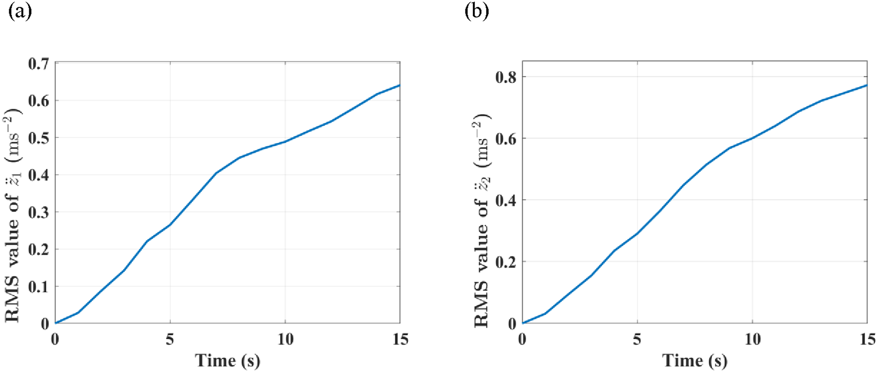
The computer is configured with i7 processor and 32 G memory. The program ran for 18 h and 57 min, of which modal analysis ran for 2 h and 32 min, and restarted for 16 h and 25 min. The simulation results are shown in Figures 8 and 9. Spatial PSDs of the responses. (a) The acceleration at the driver's seat; (b) The acceleration at the passenger seat. Frequency-weighted RMS of the responses. (a) The acceleration at the driver's seat; (b) The acceleration at the passenger seat.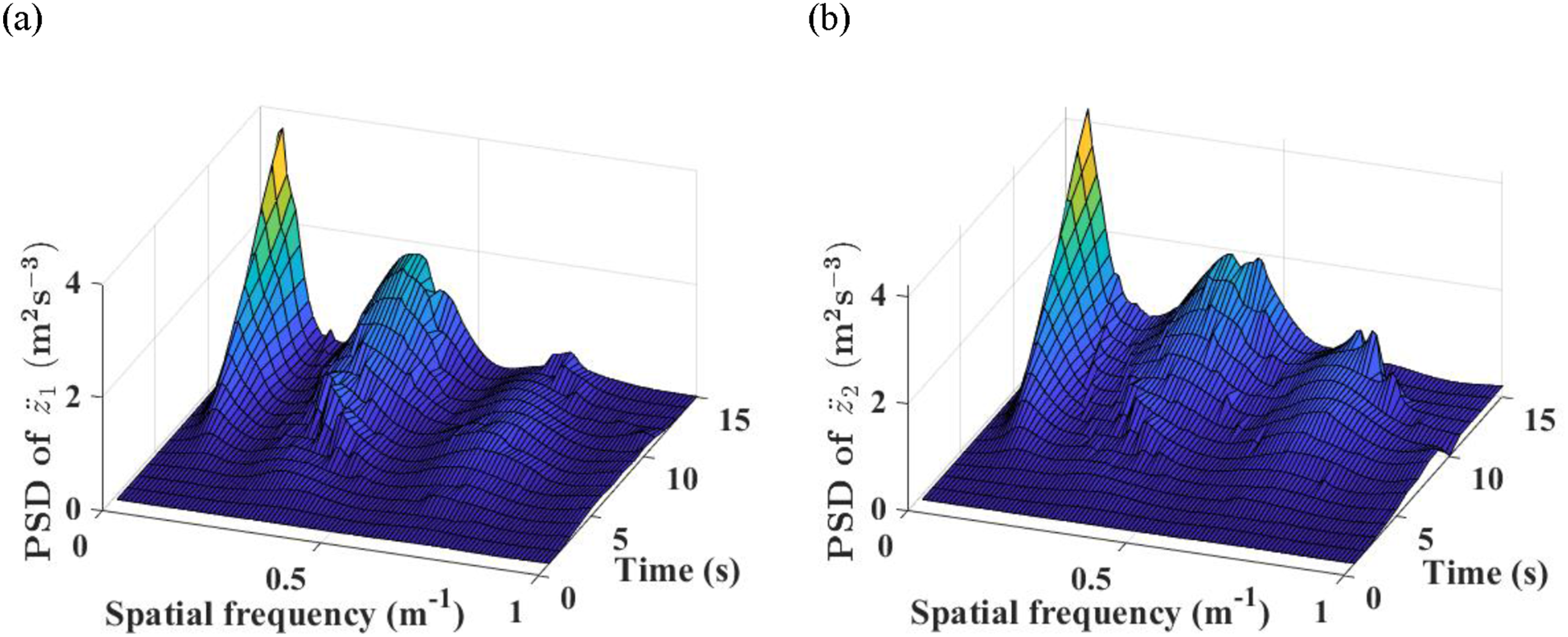
From Figure 8, the PSD of acceleration at the driver’s seat and passenger seat is closely related to vehicle speed and spatial frequency. Both increase with the rise of vehicle speed but exhibit fluctuations in certain frequency bands. The PSD of the seats reaches the maximum value at the spatial frequency of n = 0.05 m−1 and time t = 15 s, and a local maximum appears at the spatial frequency of n = 0.36 m−1 and time t = 15 s.
It can be observed from Figure 9 that the frequency-weighted RMS acceleration rises continuously with the increase of vehicle speed. The maximum value of the weighted RMS acceleration at the driver’s seat reaches 0.64 ms−2, while that at the passenger seat is up to 0.77 ms−2. In accordance with the ISO 2631 ride comfort evaluation criteria, such acceleration magnitude will cause considerable discomfort to both the driver and passengers.
Compared with stationary road excitation, non-stationary random road excitation possesses obvious time-varying statistical characteristics, which easily excites the transient vibration characteristics of the vehicle and further amplifies the overall vehicle vibration responses; as the driving speed increases, the frequency band of road excitation undergoes a continuous shift, leading to a remarkable rise in the frequency-weighted RMS acceleration specified by ride comfort evaluation criteria and consequently deteriorating the riding experience and comprehensive comfort of occupants. The analysis results reveal that the non-stationary characteristics of the road have a significant negative impact on ride comfort evaluation indices, and high driving speed produces a coupling effect with road non-stationarity to further aggravate the deterioration of vehicle ride comfort.
7. Conclusion
To address the key problem of balancing solution efficiency and accuracy for time-frequency domain non-stationary vibration of complex models in vehicle ride comfort simulation under non-stationary conditions, this paper proposes an innovative analytical method integrating FEM, transient PSD and spatial-domain PEM. Through systematic research and verification, the main conclusions are drawn as follows: (1) The FEM has the modeling capability for both simple models and high-precision complex models, which can effectively improve the accuracy of vehicle vibration models and provide a reliable modeling foundation for the ride comfort analysis of vehicles under non-stationary conditions. (2) The spatial-domain PEM can convert the non-stationary random vibration problem into a harmonic response analysis problem, avoiding the massive iterations of the traditional time-domain integration method and significantly improving the solution speed. (3) Compared with the Monte Carlo method, the simulation curves are in high agreement with a maximum error of only 5.32 %, and the simulation time of the proposed method is reduced by 90.36%, which fully verifies its validity and high efficiency in non-stationary vibration analysis. (4) The proposed method does not require the derivation of complex mathematical formulas and is mainly solved by using the harmonic response analysis module of general finite element software, featuring high solution efficiency.
This method can be applied to the ride comfort evaluation of various vehicles under non-stationary conditions, providing data support for suspension stiffness matching and seat vibration reduction optimization, and has favorable engineering application value. It should be noted that the method proposed in this paper is only applicable to linear vibration systems. Future work will extend the approach to vehicle systems with nonlinear suspension components, such as meteorological dampers and piecewise linear springs, and further improve the coherence processing of multi-point excitation.
Footnotes

Funding
The authors disclosed receipt of the following financial support for the research, authorship, and/or publication of this article: This research is supported by Project of Liaoning Provincial Department of Education [Grant no. LJKZ0199] and [Grant no. LJKZ0203], the Development Fund of State Key Laboratory of Automotive Chassis Integration and Bionics [Grant no. 20181107].
Declaration of conflicting interests
The authors declared no potential conflicts of interest with respect to the research, authorship, and/or publication of this article.