
Abstract
Recognizing the electromagnetic shunt damper (EMSD) as a vibration control device that enables versatile mechanical behavior through appropriate shunt-circuit configurations, this study investigates its application to a 10 MW steel-concrete hybrid wind turbine (HWT). An enhanced EMSD, namely, N-EMSD, composed of an electromagnetic damper (EMD), a negative impedance converter (NIC), and an RLC circuit, is employed to replace the damping unit of a conventional tuned mass damper (TMD) and to construct the analyzed mass-EMSD. First, the merits of introducing NIC for N-EMSD and the detailed mechanism of N-EMSD were presented. The NIC renders theoretically feasible the realization of versatile mechanical behaviors of the EMSD. Circuit tests for the NIC were conducted. Subsequently, a Simulink-OpenFAST coupled model is established, covering the excitation, HWT structural dynamics, and the N-EMSD with electromechanical dynamics. The control performance of the mass-EMSD is evaluated using the coupled model in the normal operation mode. The control device is applied in the side-to-side direction of the HWT. The mass-EMSD achieves promising control effects, with reduction ratios of tens of percent in the standard deviation of tower-top side-to-side displacement and the associated root-mean-square acceleration, slightly outperforming those of the TMD. In addition, the power generation and pitch control effects are analyzed in the modeling; the introduction of control devices has limited effects on these aspects. These results demonstrate that the proposed mass-EMSD is an effective control device for HWT, shedding light on the development of electromagnetic-oriented vibration control strategies for WTs.
1. Introduction
1.1. Vibration control of wind turbines
With the continued development of wind turbines (WTs), characterized by larger rotor-nacelle assemblies, more slender support towers, and deployments expanding into deep-sea regions or high-altitude cold areas, they suffer from more complicated environmental loads, potentially performing intensive vibrations, which potentially threaten their safety and affect normal operations during their service life (Wang et al., 2025; Xie and Aly, 2020; Yu et al., 2025). In this regard, a vast range of vibration control strategies has been developed for attenuating WT vibrations, including but not limited to tuned mass dampers (TMDs) (Patro et al., 2023; Yadukrishnan et al., 2024; Zuo et al., 2020), tuned liquid dampers (TLDs)/tuned liquid column dampers (Chen and Georgakis, 2015; Zhang et al., 2019), nonlinear energy sinks (Cai et al., 2024; Zuo and Zhu, 2022), and cable-based dampers (Dai et al., 2021, 2023). The passive control damper generally offers the advantages of low cost, simple configuration, and easy implementation. By further incorporating controller and sensor systems with these damper devices, semi-active and active vibration control strategies could effectively improve mitigation performance; nevertheless, they are typically associated with more complex system architectures, control algorithms, and external power supply requirements in practical applications. In particular, potential structural stability issues in active control systems should be carefully considered (Brodersen et al., 2017; Sun, 2018). In this regard, a trade-off exists between the passive and semi-active/active control, and the passive control category currently still dominates the WT control market.
Meanwhile, novel structural components, such as negative stiffness or inerter units, exhibit force-displacement characteristics similar to those of active control and have thus attracted extensive attention in vibration control (Shi and Zhu, 2015; Smith and Wang, 2004). The novel units are explored for incorporating the aforementioned passive damper types and for constructing performance-enhanced control derivatives, such as KDamper (Zuo et al., 2024), TMD-inerter (Elias and Beer, 2024), and cable-tuned-inerter damper (Dai et al., 2023). Kapasakalis et al. (2024) investigated the multi-objective optimization of KDamper, consisting of a mass with positive and negative-stiffness units, for offshore WTs, reporting superior reductions in tower peak response and effective damping compared with TMD. Zuo et al. (2024) used the KDamper to control the seismic responses of WTs and conducted a parametric analysis of its influencing factors, including connection configurations and negative-stiffness values. Zhang et al. (2019) explored the TMD-inerter for seismic-excited offshore WTs, demonstrating its lightweight design and superior robustness compared to TMDs. Dai et al. (2023) developed a cable-based tuned-inerter damper, reporting vibration-reduction performance comparable to that of a TMD but without an oscillating mass.
The mechanisms underlying the novel structural components could be realized through various approaches. Negative-stiffness unit could be realized by a snap-through pre-bucked beam (Kashdan et al., 2012), a pre-compressed spring (Pasala et al., 2013), and permanent magnets (Shi and Zhu, 2015; Zhou et al., 2019); inerter unit could be realized by rack and pinion (Smith and Wang, 2004), ball-screw (Wang and Su, 2008), hydraulic motor (Wang et al., 2011), and electromagnetic analogies (Li and Zhu, 2018). It is worth noting that introducing a negative-stiffness element may induce structural instability; the negative-stiffness-based damper, particularly for large-scale structures, requires further experimental validation. On the other hand, inerter-based damper has been explored and tested in real large-scale cables (Li et al., 2019). Note that despite rapid development, the inerter mechanism was primarily realized through mechanical designs.
1.2. Electromagnetic shunt damper
Another exciting development in passive control devices is the electromagnetic shunt damper (EMSD), consisting of an electromagnetic damper (EMD) and a shunt circuit. EMSD was first developed in the early 2000s (Behrens et al., 2003). The EMSDs offer an alternative solution for modeling various structural components, including inerter, based on electromechanical coupling effects (Firestone, 1933; Li and Zhu, 2018). The early version of EMSD is often challenged by a limited control force, which is caused by the effects of coil resistance and a relatively small machine constant. To address the low-force limitation, both mechanical and electrical approaches have been developed.
Sun et al. (2022a) developed a hybrid EMSD with a Coulomb friction mechanism, enhancing control force performance. Later, they introduced a negative impedance converter (NIC) into the shunt circuit, thereby mitigating the performance bottleneck caused by the coil resistor and increasing the damping force-to-mass ratio by 600% compared with the conventional EMSD (Sun et al., 2022b). The introduction of NIC to enhance force performance was first proposed by Yan et al. (2014), who employed an amplifier-based shunt circuit. Chen et al. (2024) recently inserted a velocity-based voltage source into the shunt circuit to improve the EMSD capacities. However, it is noted that the embedded feedback logic essentially makes the EMSD a semi-active or active control category. Stabile et al. (2017) and Li and Zhu (2018) employed a simplified NIC without control algorithms, enabling the EMSD to exhibit the expected mechanical behavior, including the inerter feature. Li et al. (2020) later demonstrated its effectiveness in a full-scale cable experiment. Regarding EMSD optimizations, Zhou and Bao (2022) and Zhou et al. (2019) conducted a series of analytical derivations, and presented different optimization designs that consider various electrical component connection configurations and optimization criteria. Note that the EMD/EMSD demonstrates the potential to be upgraded to semi-active or active control devices through appropriate current regulation of the connected circuit (Basaran et al., 2022; Cai et al., 2025; Li et al., 2024), but they also suffer from one or several of the limitations of smart vibration control as mentioned above.
1.3. Motivations
The EMSDs have been applied to stay cables (Shen and Zhu, 2015), vehicle suspensions (Cai et al., 2021), high-rise buildings (Shen et al., 2018), space structures (Yan et al., 2019), and many others (Cai and Zhu, 2022) numerically or experimentally, demonstrating success in previous studies. However, its exploration of WT applications is rare; the most relevant papers presented conventional EMSD (Zhang, 2022) and energy-harvesting/self-powered EMSD (Cai et al., 2025; Jahangiri and Sun, 2019) for offshore WT vibration control. The performance characterizations, especially the versatile equivalent mechanical behaviors of the EMSD with NIC (namely, N-EMSD) for WT, have not been explored. The EMSD without NIC generally exhibits performance bottlenecks (Li and Zhu, 2018). The explorations of N-EMSD for WT show the following merits: (1) lightweight design; the damper versatile characteristics could be easily realized by a shunt circuit instead of complicated mechanical designs, suitable for WTs where structural internal space is limited; (2) novel smart control; by tuning the shunt circuits with an appropriate control algorithm, the control force could effectively adapt to various load conditions, upgrading to semi-active or active control, yet to be validated in the future study.
This study investigates the feasibility of an N-EMSD comprising an EMD, an NIC, and an RLC circuit for WT vibration control. The contributions of this study are reflected as (1) experimentally testing an NIC, which supports the development of N-EMSD that realizes the arbitrary behaviors of equivalent inerter-based dampers; (2) establishing the full coupled excitation-WT-EMD-NIC-RLC circuit model in Simulink-OpenFAST for complicated dynamics analysis; it should be the first step for exploring semi-active EMSD for WTs. Note that the N-EMSD could be incorporated with conventional TMD for implementations. The structure of this study, after the introduction, is organized as follows: detailed modeling of N-EMSD is presented first, followed by circuit tests of NIC. Subsequently, the N-EMSD is applied for numerical WT across the normal operation mode (NOM). Then, a brief discussion on why N-EMSD is explored for WT is presented. Finally, the major findings would be summarized.
2. N-EMSD
The N-EMSD comprises an EMD connected to an NIC and an RLC circuit. This section presents the fundamental mechanism of the EMSD and the NIC-enhanced functions.
2.1. Fundamental mechanism and the necessity of NIC
Electromechanical coupling establishes the foundation of the electromagnetic shunt mechanism. The corresponding electromagnetic coupling force, representing part of the control force, is generally expressed as

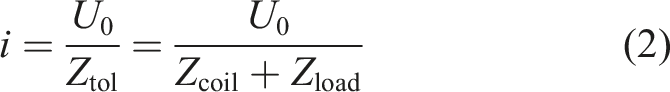


In addition to the EM force (i.e., equation (1)), the EMD performs parasitic damping due to friction or other factors. The EMSD total control is given as

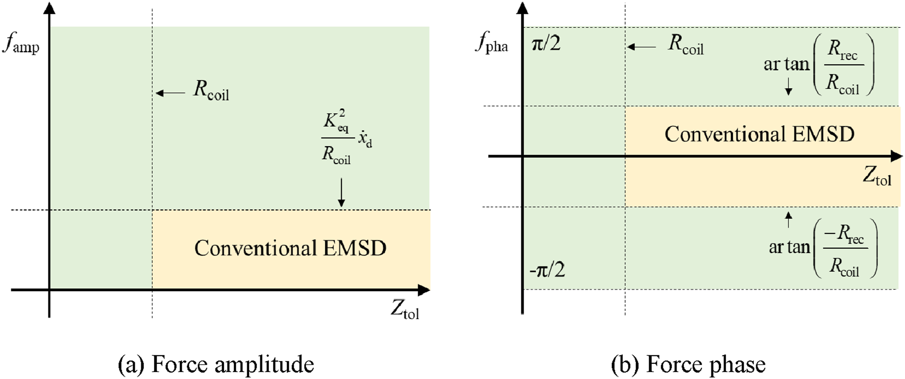
Figure 1(a) illustrates the theoretical model of conventional EMSD, wherein an RLC circuit is directly connected to the EMD. Given minimized parasitic damping, Figure 2 illustrates the region of realizable EM control force amplitude and phase (between force and velocity) using conventional EMSD, wherein Rrec denotes the load reactance. The yellow region denotes the realized performance by using conventional EMSD. It is evident that the coil resistance in the design of EMSDs limits the feasible current passing through the shunt circuit in both magnitude and phase, thereby affecting the control force behavior, a performance bottleneck. In this scene, the phase feature of the conventional EMSD can be enhanced by employing a large capacitive or inductive reactance relative to the coil resistance, or by reducing the coil resistance; the corresponding amplitude feature can be improved by reducing the coil resistance or increasing the machine constant. Thus, reducing the coil resistor effect is recognized as an effective solution to enhance the EMSD capacity (Li and Zhu, 2018). Theoretical model of EMSD and the mass-EMSD. EM control force of EMSD.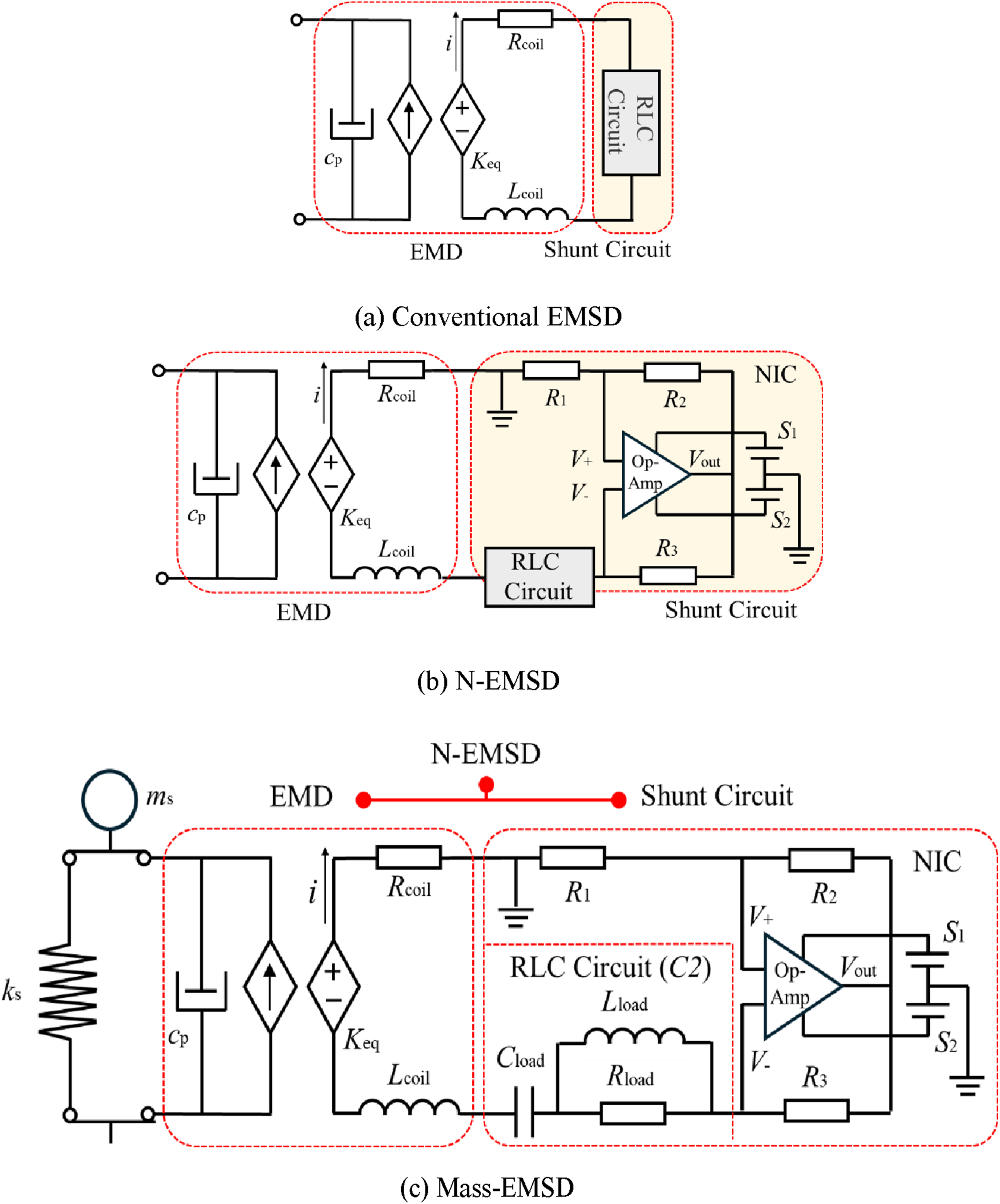
2.2. NIC
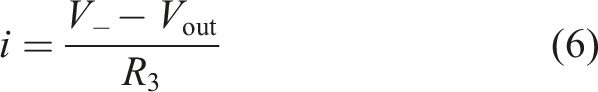
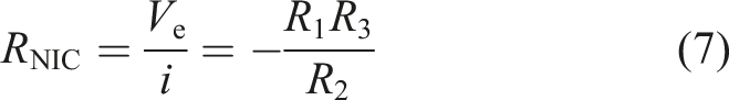
NIC consists of an operational amplifier (Op-Amp) and three resistors (Li and Zhu, 2018). It could effectively mitigate the coil resistance effect by introducing voltage compensation, thereby acting as a negative resistor. Figure 1(b) illustrates the schematic of N-EMSD (i.e., with NIC). By an ideal Op-Amp with virtual short and virtual open, the current passing through resistor R3 is given as
2.3. NIC circuit tests
Parameters of the EMSD and relevant testing devices.
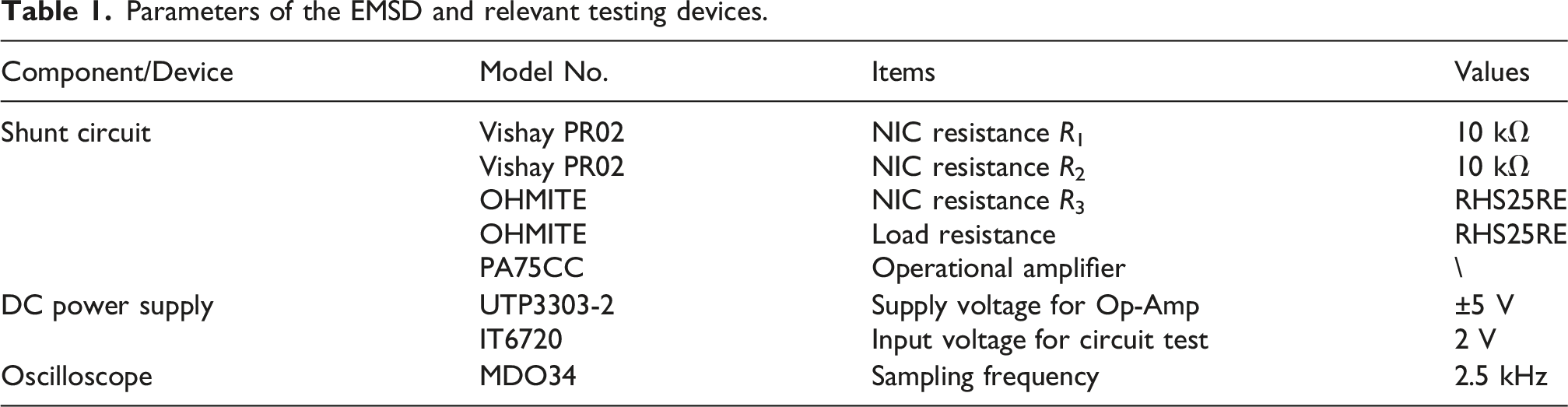
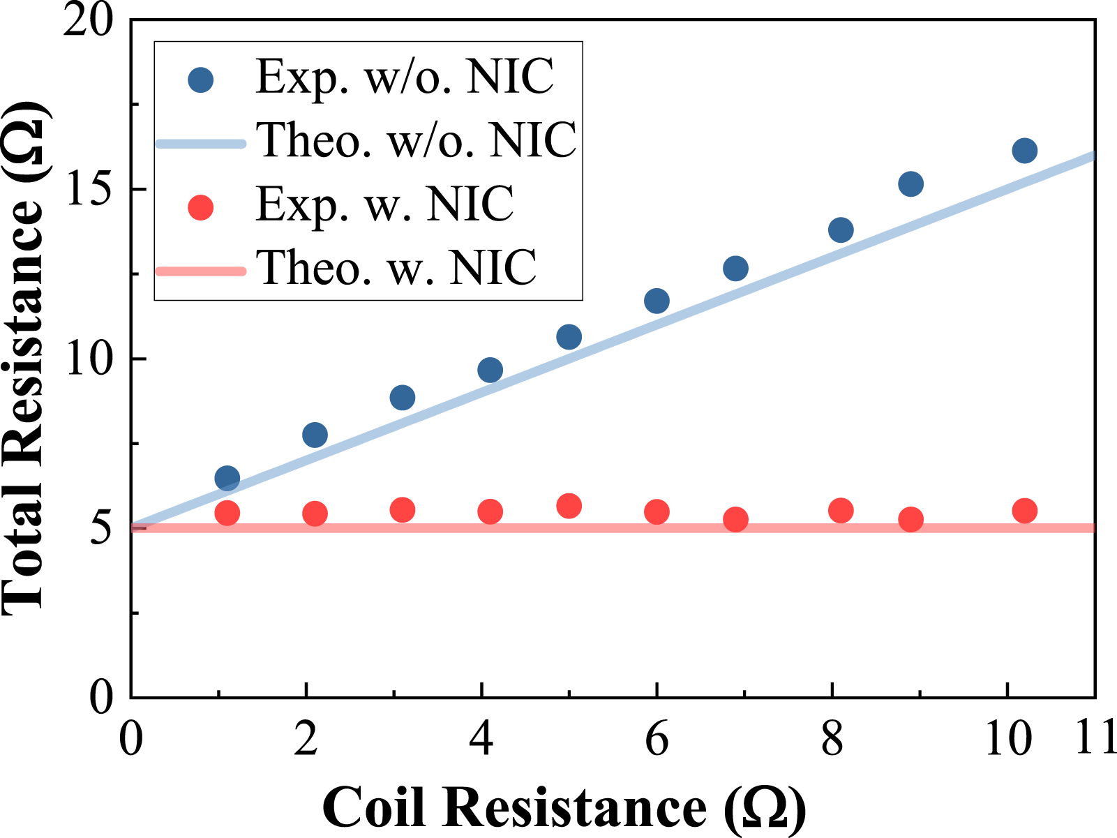
In the DC circuit test, two DC power supplies were used: one to power the Op-Amp and the other to provide a constant 2 V input for the shunt circuit. Various external resistances were introduced to emulate different coil resistances, which were connected in series with a constant load resistance of 5 Ω. Figure 3(a) shows the tested NIC circuit on a breadboard, and Figure 3(b) shows the corresponding test setup. Figure 4 shows the experimental total resistances (i.e., Rload + Rcoil) with and without NIC. It is evident that with increasing coil resistance, the total resistance should increase; however, with the adoption of NIC, the total resistance remains nearly identical to the load resistance. This result demonstrated the effectiveness of NIC in eliminating the coil resistance effect, supporting the application of N-EMSD. Cyclic tests of the N-EMSD will be included in the future study. Experimental tests of NIC. Total resistance in circuit tests with and without NIC.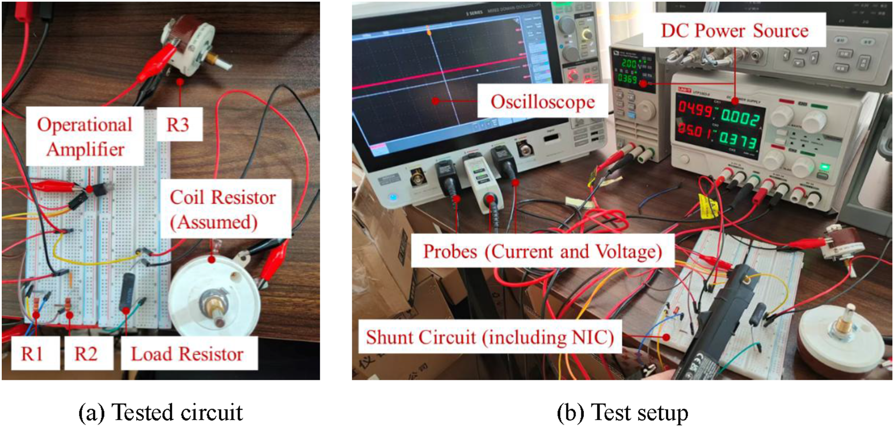
2.4. Mass-EMSD control
In this study, the N-EMSD is assumed to incorporate TMD further by replacing its damping unit before being applied to the WT, referred to as the mass-EMSD. Similar integrations with other control devices (e.g., cable-based dampers) should be straightforward. In this scene, the governing equation of a mass-EMSD for a single-degree-of-freedom (SDOF) structure, representing a controlled-vibration mode, can be generally expressed as
Figure 5 presents the optimal performance achieved by equation (9) with the shunt circuit (a resistor-inductor in parallel and a capacitor in series), wherein the controlled-vibration mode is set as the first-order side-to-side mode of the hybrid wind turbine (HWT). The reason for selecting the side-to-side mode is that fore-aft vibration response control might not be as urgent in NOM, where aerodynamic damping is considerable (Cai et al., 2026). The detailed HWT and EMD parameter settings can be found in Section 3. It can be observed that (1) the mass-EMSDs and TMD effectively mitigate the vibration amplitude; and (2) the mass-EMSD results perform three nearly identical peaks, generally outperforming the optimal TMD, but to a limited degree, with only about 5% improvement in peak reduction. The result demonstrates the effectiveness of mass-EMSD for vibration control, which is slightly superior to that of a TMD. Comparisons of the main structural displacement frequency-response function between mass-EMSD and TMD.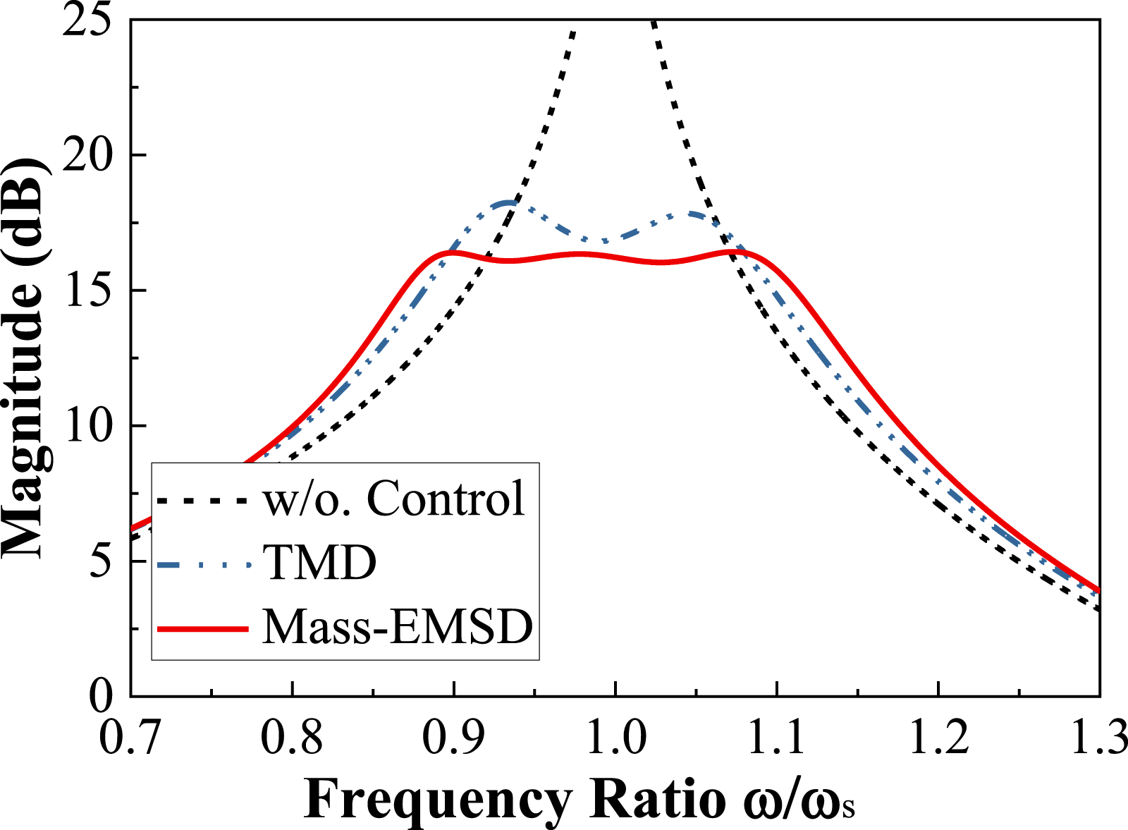
3. Excitation-WT-control device model
3.1. Steel-concrete 10 MW HWT
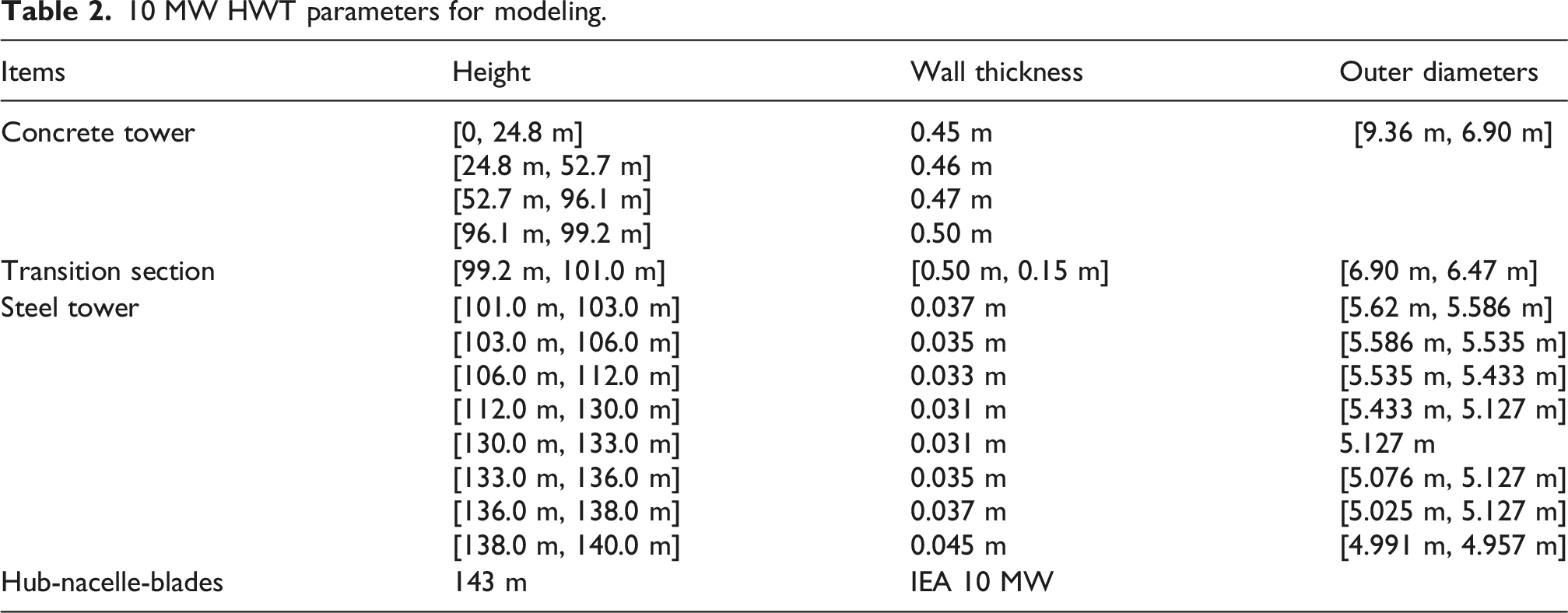
A steel-concrete 10 MW HWT, a newly developed onshore WT configuration, is employed to validate the N-EMSD. Figure 6 presents the HWT diagram with mass-EMSD, and Table 2 lists the corresponding HWT tower parameters for modeling. The HWT tower mainly consists of three sections: (1) a concrete tower with a 99.2 m height; the tower’s outer diameter tapers linearly from the base of 9.36 m to the top of 6.90 m; the tower’s thickness is irregular, as listed in Table 2; the mass density and elastic module of concrete material are 2500 kg/m3 and 38 GPa, respectively; (2) a transition section of 1.8 m height; the outer diameters and wall thickness at this section base are 6.90 m and 0.50 m, respectively, while those at the section top are 6.47 m and 1.50 m, respectively; it is mainly constructed by concrete as well (Assumption for the transition section). The prestressed steels are anchored at the top of this section and the concrete tower base, with a total prestressed force of 2.80 × 10⁵ kN; (3) a steel tower with a 39 m height; the variations of the tower’s thickness and outer diameter are irregular along with the tower height, as listed in Table 2; the mass density and elastic module of concrete material are 8500 kg/m3 and 206 GPa, respectively. The typical 10 MW IEA WT hub, nacelle, and blades are applied for the HWT (Bortolotti et al., 2019). Schematic of an HWT with mass-EMSD. 10 MW HWT parameters for modeling.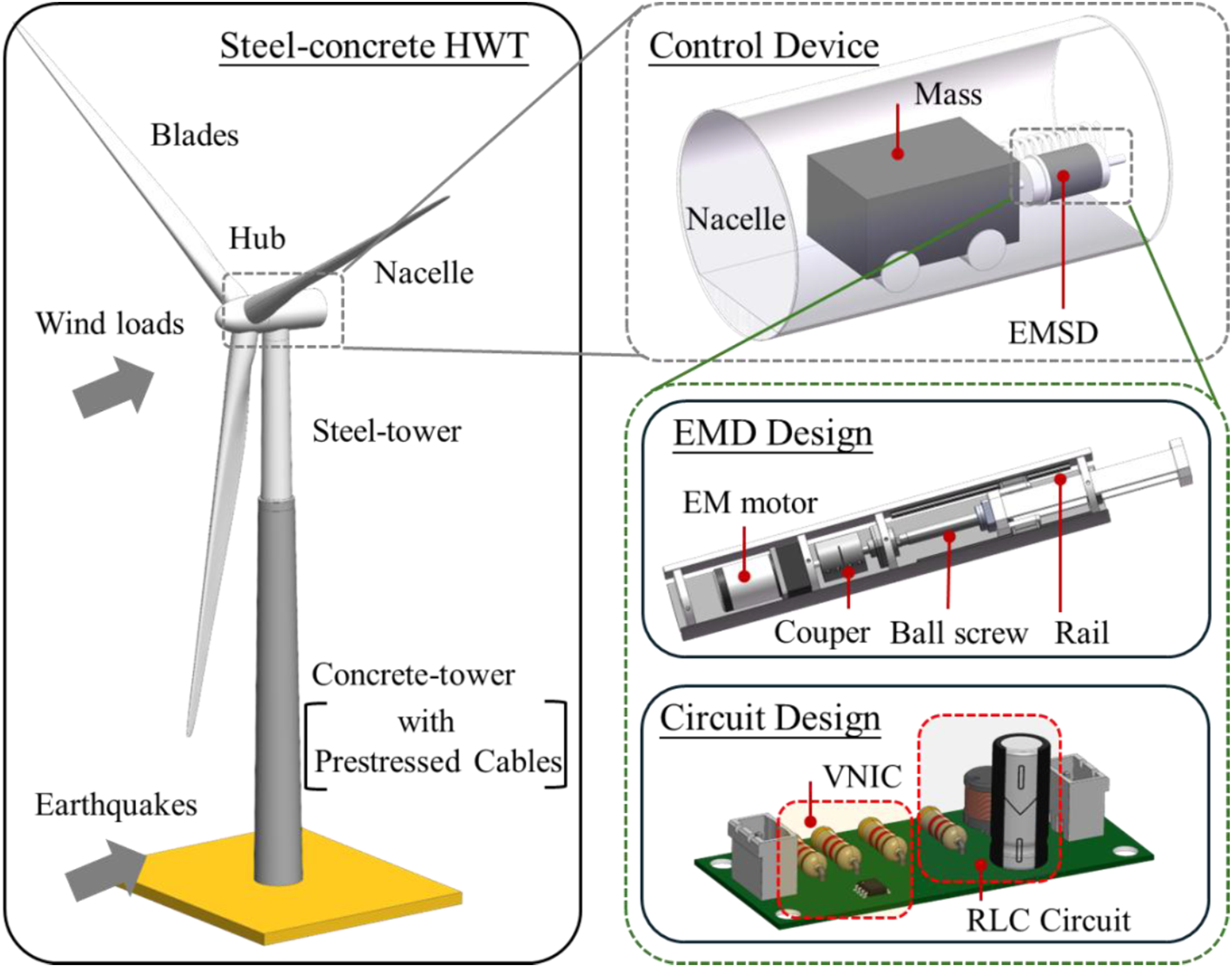
3.2. Simulink-OpenFAST coupled model
The 10 MW HWT is established by modifying the 10 MW IEA WT model in OpenFAST, in which the “ElasoDyn” and “AeroDyn” modules are adjusted based on the steel-concrete tower properties. The wind field is generated in the Turbsim module of the OpenFAST software using the Kaimal spectrum. In the existing OpenFAST software, only the typical TMD and TLD are embedded in the structural control module. Referring to Cai et al. (2026), a customized development of the OpenFAST is performed by modifying the original code with updated program files, including but not limited to the S-function file and openfast.dll file; a Simulink-OpenFAST coupled model is established, in which the developed mass-EMSD is implemented in Simulink, while the HWT and wind loads are generated in OpenFAST, with collective pitch control accounted for during modeling. OpenFAST provides the HWT tower-top vibration acceleration “YawBrTAgy” to the mass-EMSD in Simulink, which, in turn, provides the mass-EMSD control force to the HWT nacelle in OpenFAST. In the modeling, the HWT is treated as a fixed onshore configuration with the “BCmod” setting set to 1. Figure 7 presents the established model, which uses Simulink and Simscape blocks to model all circuit components. Note that the control device is applied in the side-to-side direction of the HWT, and only this directional response is analyzed in this study. Also note that the NOM refers to the power production situation in the IEC design (IEC, 2019). Coupled model of HWT with mass-EMSD.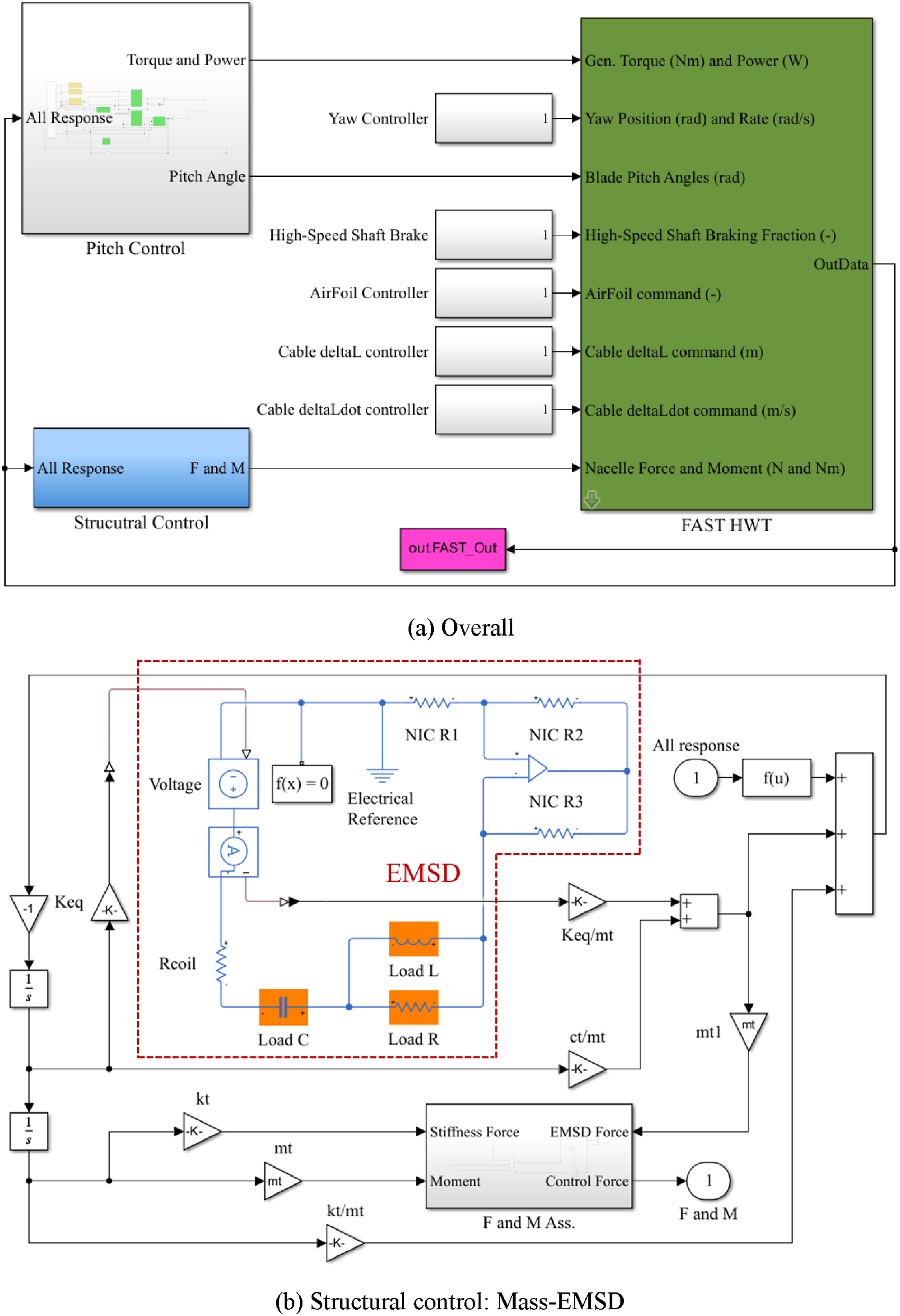
The mass ratio of the mass-EMSD is set at 2% of the first-order vibration modal mass of the HWT, which is approximately 2.20 × 10⁴ kg. The EMD parameters are selected as Keq = 100 N/A; Rcoil = 5 Ω; cp = 60 N•s/m. To minimize the NIC’s power consumption, the resistors R1 and R2 are deliberately set to 10 kΩ. The NIC resistor R3, equal to Rcoil, is set to 5 Ω to eliminate the coil resistance effects. Note that an ideal Op-Amp is employed; thus, no saturation issues are considered in the modeling. In practical applications, a high-power supply can minimize the risk of saturation. Following the optimization process in Subsection 2.4, the optimized parameters of the mass-EMSD are kt = 81.24 kN/m, Rload = 16.72 Ω, Lload = 2.72 H, and Cload = 0.105 F. The conventional TMD cases (ctmd = 7.19 kN•s/m; ktmd = 80.0 kN/m) are used for performance comparisons, following the H∞ displacement-optimization approach. A specific coupled model with TMD application can be established similarly, whose model schematic is not presented in this paper for conciseness.
In the modeling, wind loads are output over an 800 s time duration with a time step of 0.05 s. Wind speed cases ranging from 4 m/s (cut-in speed) to 25 m/s (cut-out speed) are modeled, covering the NOM. The collective pitch control is always applied in NOM. Each load case is conducted 10 times for performance evaluation to minimize the influence of random seed variations in wind loads. Figure 8 illustrates one example time history of wind speed at 16 m/s. It can be observed that the steady wind speed remains approximately 16 m/s, as expected, while also exhibiting turbulence. Other wind speed cases made similar observations; therefore, they are not presented for paper conciseness. Example of wind speed at 16 m/s.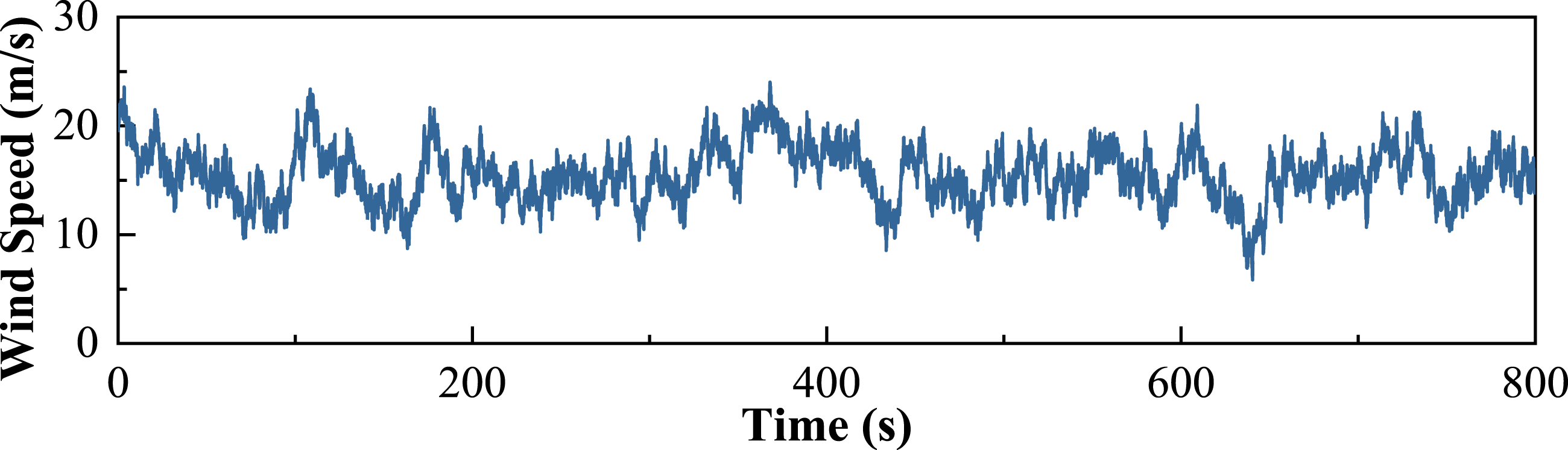
4. Numerical results and discussions
This section presents the time- and frequency-domain results of the HWT with the mass-EMSD, using a wind speed of 16 m/s as the representative case of NOM, followed by an analysis across different wind speed conditions. Only the last 600 s steady-state vibration responses are employed for performance evaluation. As mentioned, the following analysis is for the side-to-side directional response unless otherwise stated.
4.1. Time and frequency-domain results
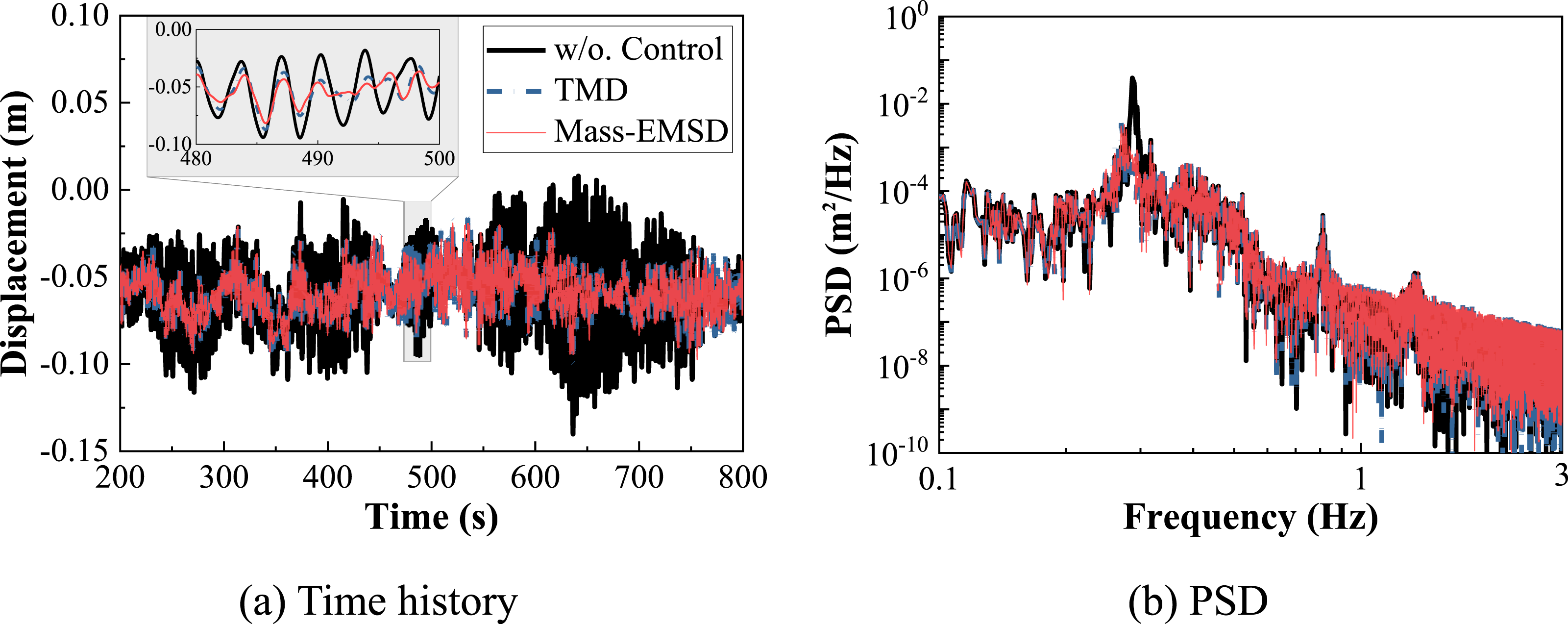
By taking one wind speed case of 16 m/s as the example, Figure 9(a) presents the tower-top side-to-side acceleration (“YawBrTAyp”) of the HWT with and without mass-EMSD. The root-mean-square (RMS) acceleration is slightly reduced from 0.090 to 0.055 m/s2, corresponding to a 39% reduction. The TMD results are also reported for comparison, which are nearly identical to those of mass-EMSD. Figure 9(b) illustrates the corresponding power spectral density (PSD), indicating that the mass-EMSD mainly reduces the first vibration mode of the HWT as designed. Figure 10 shows the corresponding tower-top displacement (“TwrTpTDyi”) of the HWT. Similar observations are made: a 49% and 47% reduction in the standard deviation of displacement for mass-EMSD and TMD, respectively; both are effective only in the first vibration mode. These results demonstrate that under NOM, the mass-EMSD can achieve considerable side-to-side vibration reduction; however, the control improvement relative to TMD is limited. Employing an active controller should enable a more significant improvement in control performance. Tower-top accelerations of HWT: wind speed of 16 m/s. Tower-top displacement of HWT: wind speed of 16 m/s.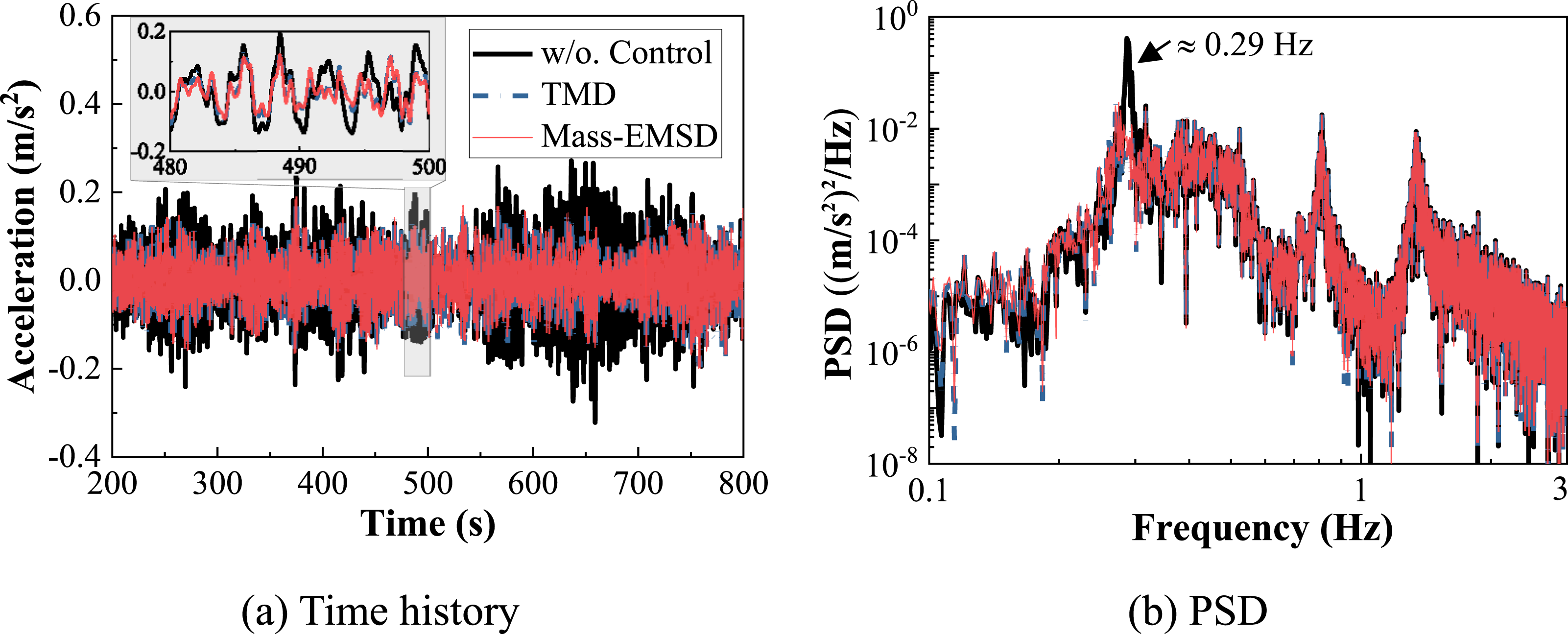
Corresponding to a wind speed of 16 m/s, Figure 11 depicts the time histories of power generation and the pitch control angle. It can be observed that the generated power is generally maintained at the rated level of 10 MW through the pitch control. The results indicate that pitch control remains active during the application of vibration control. Notably, the power output and pitch angle responses in the uncontrolled and controlled cases are nearly identical, demonstrating that, within the current modeling framework, the pitch control and structural vibration control systems operate as independent control modules. Further integration of these two control strategies is expected to enhance the overall control performance (Tang et al., 2024). It is worth noting that in most existing studies on WT vibration control, the pitch control-associated aerodynamic damping are often neglected, which may lead to an overestimation of vibration mitigation effectiveness in the corresponding assessments. Power and pitch angle of the HWT: wind speed of 16 m/s.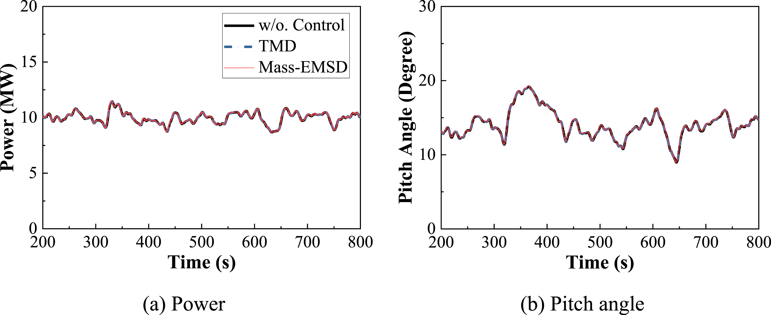
4.2. Different wind speeds
Figure 12(a) and (b) show the corresponding statistical acceleration and displacement response across NOM, respectively. Figure 13(a) and (b) show the corresponding reduction ratios of the RMS acceleration and the standard deviation of displacement, respectively. The following observations are made: (1) under NOM, the tower-top side-to-side RMS acceleration generally increases with wind speeds. Similar RMS displacement results are observed. The side-to-side statistic responses are quite significantly different from those in fore-aft direction (not presented due to the page limits), but both are relatively small due to the conservative HWT structural design, characterized by high stiffness; (2) the reduction ratios of RMS accelerations and standard deviation of displacement are quite significant at low wind speeds. However, they cannot serve as a useful reference because the corresponding vibration responses in this range are actually small; (3) generally, both reduction ratios maintain quite steady under NOM when the wind speeds exceed the rated value (i.e., 11 m/s). Specifically, the RMS acceleration reduction ratio achieved by the mass-EMSD is approximately 30% from wind speeds of 11 m/s to 25 m/s, while the corresponding reduction ratio in standard deviation of displacement is about 40%; (4) the mass-EMSD control improvement is limited, with 2%–4%, compared to the TMD in this HWT application, which meets the general finding by the theoretical analysis in Figure 5. The results demonstrate the effectiveness of mass-EMSD for HWT vibration control, comparable to that of the TMD. Notably, the mass-EMSD offers greater potential for control flexibility and expandability. Vibration control performance of mass-EMSD across NOM. Vibration control performance of mass-EMSD across NOM.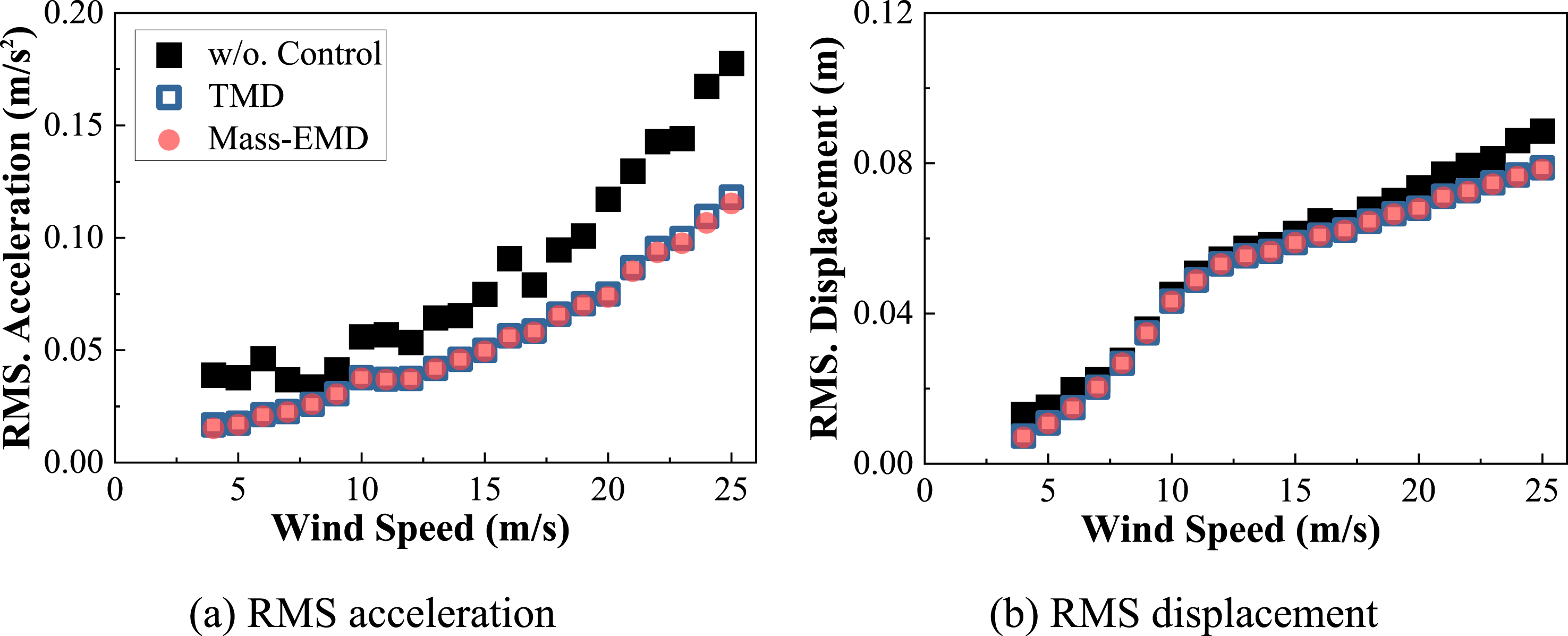
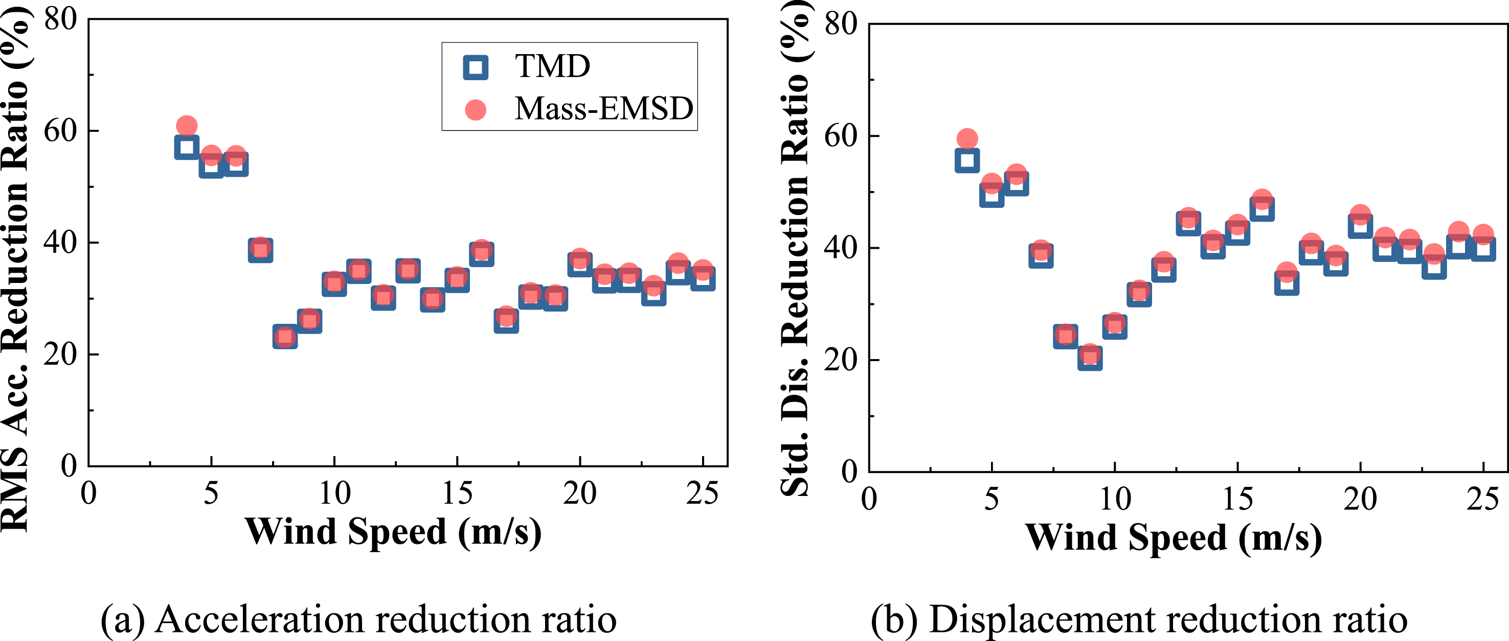
Figure 14 presents the corresponding power generation and pitch angle across the NOM, confirming that the introduction of the control device does not interfere with the current HWT pitch control modulus or power generation performance. The integration of vibration and pitch control is expected to enhance vibration control effectiveness, which will be explored in future work. Power and pitch angle of mass-EMSD across NOM.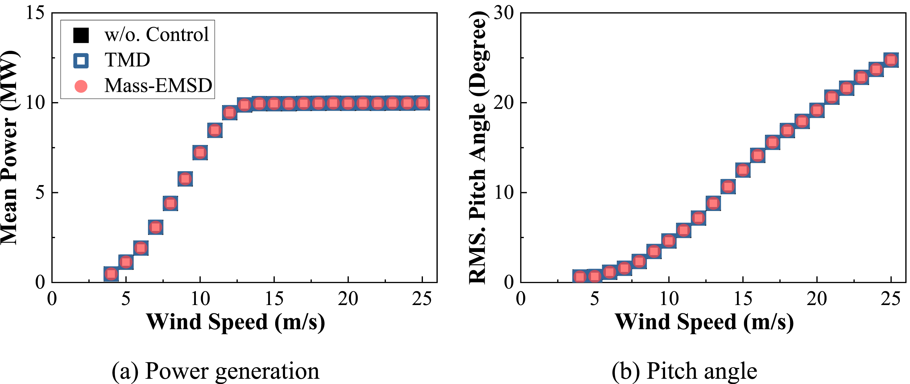
5. Clarifications on the use of N-EMSD for WTs
Although the enhancement of using mass-EMSD over TMD is not significant as expected, and it might incur additional costs and degrade performance robustness due to the introduction of system complexity, it does show certain merits and motivations for using N-EMSD for WTs: (1) WT is essentially a nonlinear structure whose structural parameters generally vary with wind speeds/blade rotating. Using an adaptive controller across different wind speed scenarios should improve vibration control performance. N-EMSD offers greater convenience for adaptive control, as its mechanical behavior depends on the shunt circuit. Employing different optimal shunt circuits with switching logic or adaptive circuit topologies for N-EMSD should not be a technical challenge. (2) The limited control performance of mass-EMSD relative to the TMD does not indicate a loss of the developmental significance of the N-EMSD. The main reason for the limited improvement is that the damping unit of the TMD has only a limited impact on its control capacity; replacing it with N-EMSD thus provides only limited improvement. The N-EMSD provides an alternative solution to realize tuned-inerter damper-like behaviors. It can be explored for integration with other control devices, such as a cable-based damper as the energy-dissipation component, in other structural applications, such as high-rise buildings and vehicle suspensions. (3) In this study, EMSD is a passive control device. However, according to the electromagnetic coupling mechanism, it can be upgraded to a semi-active inerter/damping/stiffness device and even an active control device, significantly enhancing control capacity. Its application to WT denotes a novel exploration. Further semi-active or active control by EMSD should provide significantly enhanced control capabilities.
It is worth noting that EMD-based control typically involves an electrical circuit topology, resulting in a more complex control system than conventional viscous dampers but avoiding issues such as oil leakage. Also note that the EMSD typically contains parasitic damping. Even if the circuit fails, the EMSD would not totally fail.
6. Conclusions
This study investigated the feasibility of mass-EMSD for HWT vibration control, in which the mass-EMSD is constructed by applying the N-EMSD to replace the damping unit of a TMD. The N-EMSD consists of an EMD, an NIC, and an RLC circuit. The NIC is introduced to eliminate the coil resistance effect, enhancing the control capacity of the conventional EMSD. The NIC was experimentally validated through circuit tests, and the mass-EMSD performance is evaluated on a 10 MW HWT under NOM. The results demonstrate the effectiveness of the mass-EMSD for HWT vibration control, shedding light on the development of a novel passive-control strategy for WT applications. The major findings are summarized as follows: (1) The circuit test results demonstrated that the NIC effectively compensates for the coil resistance, supporting the development of N-EMSD to realize the prescribed mechanical behavior as designed. (2) The mass-EMSD outperforms the TMD in the case of an SDOF controlled structure/mode. The mass-EMSD, in which a shunt circuit of a parallel resistor-inductor branch is connected in series with a capacitor, essentially becomes a 2DOF control device; the corresponding frequency-domain result shows three reduced peaks compared to the TMD case. (3) The mass-EMSD can reduce the HWT tower-top side-to-side response significantly under NOM, with RMS acceleration reduction ratios ranging from approximately 20% to 40% as the wind speed increases from 11 to 25 m/s, and corresponding reductions of about 20% to 50% in the standard deviation of displacement. The results demonstrate the effectiveness of passive control in HWT side-to-side response. (4) A Simulink-OpenFAST coupled model is developed that, for the first time, fully considers the coupling effects between the excitation, HWT, and the electromagnetic damping mechanical with the electrical circuit dynamics. Compared with decoupled or weakly coupled modeling approaches, the established model should provide more accurate and reliable dynamic responses.
Footnotes
Funding
The authors would like to acknowledge the financial support from the National Key Research and Development Program of China (Grant No. 2024YFF0505400), National Natural Science Foundation of China (52578596, U24A20177), Science & Technology Department Program of Sichuan Province (2025ZNSFSC1311, 2025YFHZ0249, 2026YFHZ0264), Qingdao Science & Technology Department Project (2511gjgg50hy), and the Fundamental Research Funds for the Central Universities (YJ202405). However, the findings and opinions expressed here are those of the authors alone and not necessarily the views of the sponsors.
Declaration of conflicting interests
The authors declared no potential conflicts of interest with respect to the research, authorship, and/or publication of this article.