
Abstract
To address the problem of repeated manual alignment in the multi-angle surface machining of clutch housings, a single-alignment control method based on kinematics modeling for non-RTCP (Rotational Tool Center Point) machine tools is proposed. Unlike traditional processes that require manual re-alignment after each A-axis rotation, the proposed method first establishes and solves the machine tool kinematic model to derive accurate machining coordinate transformation formulas. A dedicated digital machine model is constructed, motion logic between kinematic axes is optimized, and an interactive interface between the machine tool and CAM (Computer Aided Manufacturing) software is developed. CNC (Computer Numerical Control) system macro-program secondary development is implemented for customized machining safety control, and a specialized post-processor is built by extracting key machining parameters. Tool paths are post-processed in CAM software, and generated NC (Numerical Control) programs are verified via simulation and actual machining. The results show that the method eliminates repeated manual alignment entirely, reduces setup time and human-induced errors, and adapts perfectly to non-standard modified machine tools, providing a practical and efficient solution for multi-face machining of clutch housings.
1. Introduction
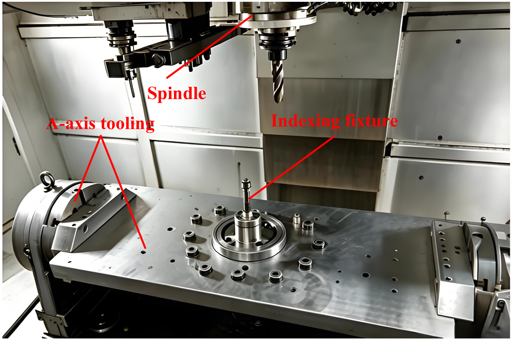
The clutch is a critical component within the automotive engine assembly, playing an essential role in transmitting and interrupting power flow between the engine and the transmission system. As illustrated in Figure 1, the clutch housing features multiple angular surfaces that serve as assembly interfaces, requiring precise machining from various orientations. In typical manufacturing processes, many mechanical processing enterprises adopt a cost-effective solution by integrating an A-axis indexing fixture into a conventional three-axis vertical machining center. This integration upgrades the original three-axis machine tool, enabling the cutting tool to achieve relative rotational motion around the X-axis. Consequently, the machine tool gains the capability to approach the workpiece from multiple preset angular positions. Furthermore, the workpiece is directly mounted onto the indexing fixture, which can rotate the clutch housing about its own axis of rotation. Through the coordinated use of the A-axis fixture and the workpiece rotation, the standard three-axis vertical machining center is effectively endowed with 3 + 2 fixed-axis machining capabilities, as depicted in Figure 2. With this upgraded structural configuration, the equipment can accomplish multi-angle surface machining of clutch housings via sequential intermittent rotary positioning motions. However, it is important to note that this retrofitted multi-axis machine lacks the RTCP (Rotational Tool Center Point) function (Han et al., 2026). Consequently, internal real-time coordinate transformation is not supported by the CNC system, which hinders its application in continuous five-axis machining and confines it to feasible 3 + 2 fixed-axis machining scenarios. Clutch housing. Multi-axis machining center.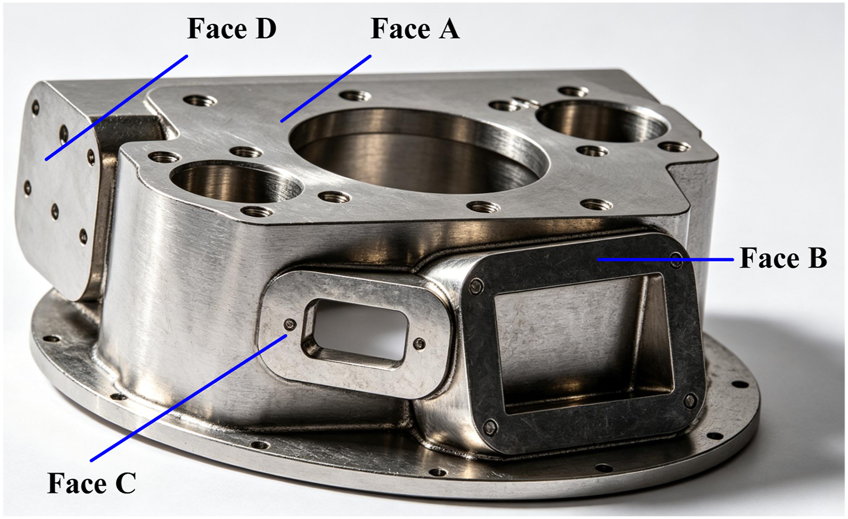
Post-processing refers to the transformation of abstract machining paths and operations into execution instructions for a specific machine hardware. This transformation process covers tool trajectory optimization, additional operation code injection, and coordinate system mapping in multi-axis machining scenarios, which ensures that the design intent can be accurately implemented in the machining process, and is a key technology in CNC machining. Wei et al. (2024) employed an improved genetic algorithm to address the post-processing algorithm for the kinematic problem of five-axis CNC machines. Li et al. (2025) developed a design optimization strategy for the dual rotary table of five-axis CNC machine tools. Ma et al. (2025) developed a reliability-based design optimization framework for a cradle-type double rotary table of a five-axis machining center, addressing random uncertainties in material properties and manufacturing error.
Xu et al. (2025) proposed a dual NURBS curve interpolation algorithm for five-axis synchronized motion, which achieves synchronous control of tool position and orientation and significantly improves machining accuracy, efficiency, and motion smoothness. Chu et al. (2023) used a universal and intuitive framework based on novel inverse kinematics formulations for three main groups of 5-axis CNC machines to enable the practically effective creation of post-processors for all possible 5-axis CNC machine configurations and working mechanisms. Zekalmi et al. (2024) developed a custom post-processor based on the PSO algorithm that utilizes the machine’s inverse kinematic model to optimize post-processing trajectory paths, taking into account both geometric and kinematic errors for five-axis machine tool compensation. Cai et al. (2023) developed a post-processing algorithm for five-axis CNC machine tools under rotation angle optimization, which uses the Hausdorff distance to calculate the matching error between the actual and theoretical machined surfaces and establishes an error compensation method, followed by the construction of a machine coordinate system and coordinate transformation to enable the conversion of tool location data into CNC codes while minimizing rotational axis deviations. Li et al. (2026) proposed a fusion and decoupling method for spatial geometric errors in five-axis CNC machine tools based on unscented Kalman filter, which integrates dual ballbar and inertial measurement unit measurements at multiple nodes on a hemispherical measurement grid to overcome the spatial circular measurement limitations of conventional DBB methods while maintaining equivalent accuracy and enabling the identification of errors on arbitrary NURBS curves with demonstrable decoupling capability. Zhang et al. (2024) proposed an optimal proportion compensation method that identifies key geometric errors considering multiple-direction coupling effects in five-axis machine tools, enabling selective compensation of the most influential error sources rather than attempting full error correction. Due to the difference in the structure of the machine tool and the difference in the CNC system, the rules for the post-processor to translate the tool position source file generated by the CAM programming software to the NC file of the CNC system may vary to a different extent, to a different degree of change. In addition, as machine tool manufacturers continue to upgrade the processing functions of the machine tool, the quality of the post-processor will determine the quality of the CNC code, affecting the efficiency of the processing, and in some cases, causing machining accidents for the project to bring a negative impact. For specific types of machine tools and CNC systems, we should develop a safe, accurate, and efficient post-processor to further improve the quality of parts processing and productivity.
2. Post-processing development overall process
The essence of machine tool post-processing is the conversion of tool position files into executable NC programs. Prior to the development of a post-processor, it is necessary to clarify the general workflow of post-processing, as illustrated in Figure 3. Specifically, three main tasks must be carried out according to the structural characteristics of the CNC machine tool: kinematic solution, nonlinear error checking, and tool position file format conversion. The kinematic calculation constructs the correlation between tool posture under the workpiece coordinate system and each motion axis of the machine tool. Nonlinear error checking addresses the deviations introduced by the interpolation of rotary axes during multi-axis machining. Format conversion restructures the tool position data to comply with the input requirements of the subsequent NC file generation stage. Furthermore, during the generation of NC files, all output must strictly follow the syntactic characteristics and programming conventions of the target CNC system, including the definition of G-codes, M-codes, coordinate word formats, and fixed cycle instructions. In summary, post-processing development requires a comprehensive understanding of both the machine tool’s kinematic configuration and the target CNC system’s syntax specifications. Post-processing overall flow.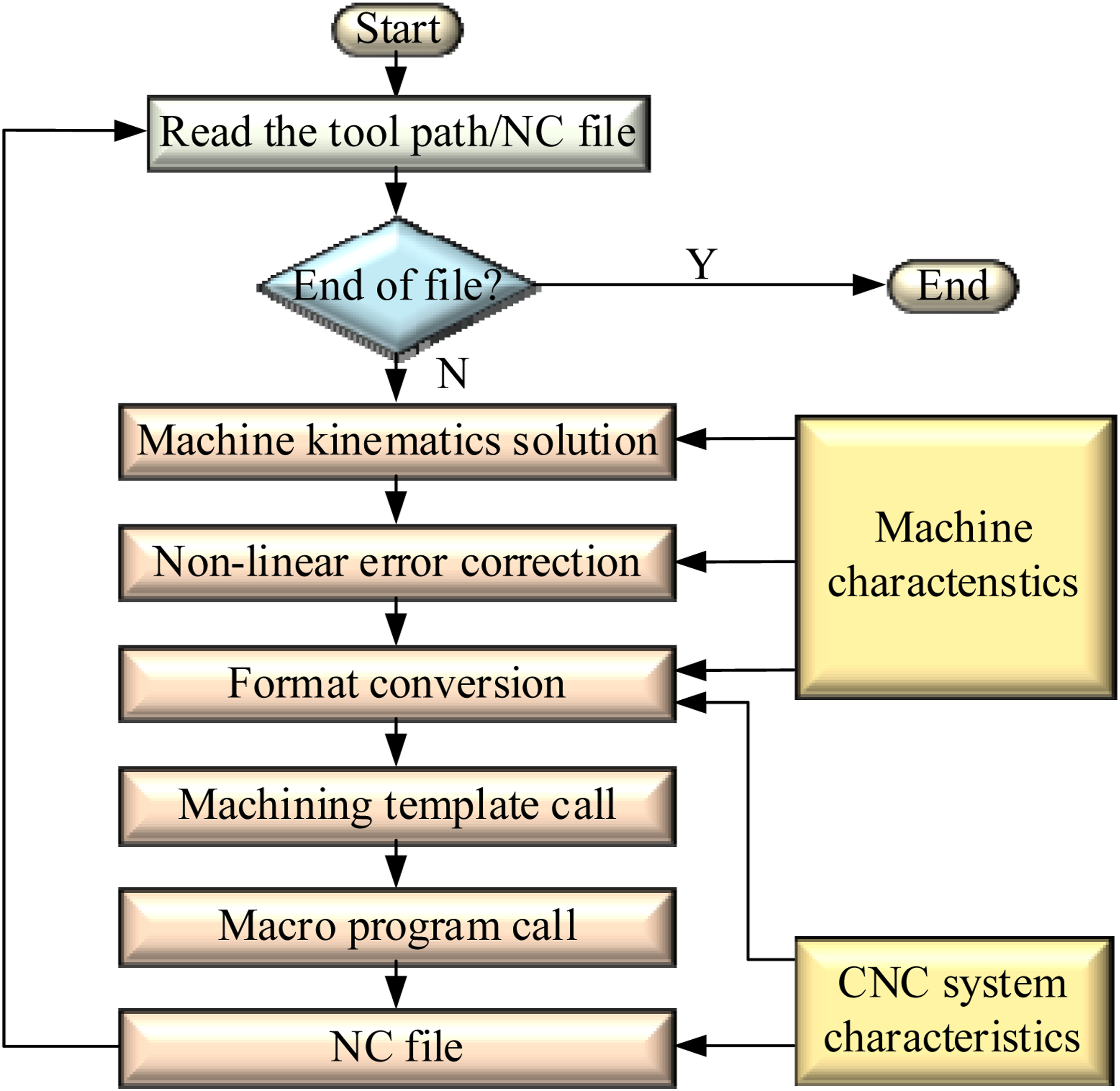
For the processing characteristics of the clutch housing, whenever the A-axis rotates to a new angular position after completing the machining of one angular surface, the operator is required to manually re-establish or re-align the workpiece machining origin (i.e., the part zero point) for the subsequent surface. The manual work of measuring and redefining the workpiece coordinate system remarkably decreases production efficiency and causes inconsistent machining quality.
To address this problem, this paper takes the clutch housing as the experimental object and proposes a systematic solution. Firstly, the kinematic model of the retrofitted machine tool (three-axis vertical machining center integrated with an A-axis fixture) is established, and the transformation relationship of the machining coordinate system before and after the tool movement is rigorously derived after the addition of the A-axis. This step clarifies how the workpiece coordinate system shifts as the rotary axis changes its angular position.
Secondly, based on the kinematic analysis, a dedicated post-processor tailored to this specific type of machine tool is developed. Unlike conventional post-processors, this specially designed one automatically calculates and outputs, within the NC file, the correct machining origin coordinates for each angular surface. By embedding the coordinate transformation logic into the post-processing stage, the need for the operator to manually search for or re-align the workpiece origin during machining is completely eliminated, thereby improving both efficiency and consistency.
Finally, to validate the reliability and accuracy of the NC files generated by the developed special post-processor, both virtual simulation (e.g., using VERICUT software) and actual on-site machining experiments are conducted. The simulation results confirm the absence of collisions and overtravel issues, while the physical machining outcomes demonstrate that all angular surfaces are machined within the required tolerances. Thus, the effectiveness and practical value of the proposed post-processing method are fully verified.
3. Machine kinematics solution
Due to the mechanical errors of the machine tool, control errors of the servo system, tool wear, and the accuracy limitations of the NC code, the tool point error is easily generated, which describes the deviation between the actual tool center point (TCP) and the intended or programmed path. The CLSF file generated by the CAM software can be used to record the linear coordinates of the tool point and the tool vector information. The workpiece is usually kept stationary when simulation machining is performed, and the tool carries out coordinate positioning and tool axis vector transformation on the workpiece. Nevertheless, in practical machining scenarios, the rotation centers of the cutting tool and workpiece fail to align with the tool center point, thus giving rise to tool position deviations induced by angular variations of the rotary axis. As shown in Figure 4(a), take the A-C cradle machine tool as an example, now need to process a point p on the workpiece of the rotary machine tool, in accordance with the linear coordinate positioning and accompanied by the workpiece rotary interpolation to determine the tool position point, in which the A-axis rotational angle of θ, as shown by the dotted line in the figure, if the center of rotation of the workpiece is at the position of the tool position point T0, there will be no error. The actual center of rotation of the machine tool is at the position of A0. At this time, it will cause a tool position offset Y0 and Z0. Similarly, as shown in Figure 4(b), the pendulum head machine will also be offset when machining the p-point, which will not be repeated here. Therefore, the machine needs a linear position compensation for Y0 and Z0, which is called RPCP (Rotation Around Part Center Point) for rotary table machines and RTC (Rotation Tool Center Point) (Li et al., 2024) for pendulum head machines. RTCP processing principle.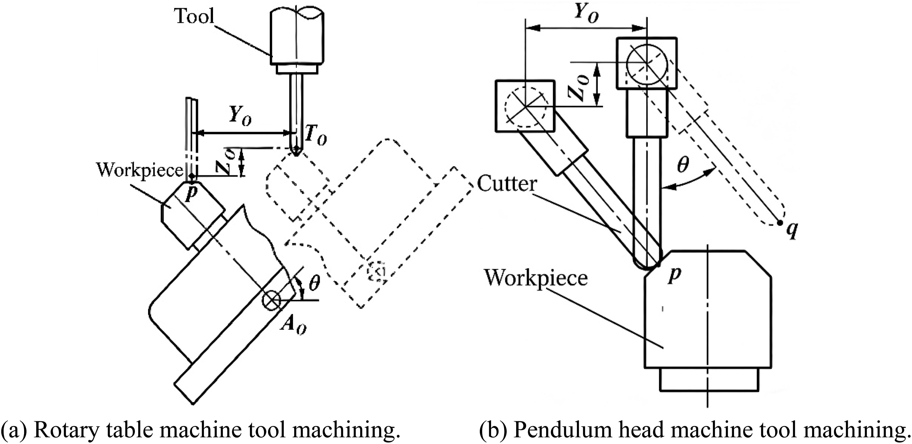
Vertical machining centers installed A-axis tooling after the right view shown in Figure 5. Whenever the tool rotates on the tooling anywhere on the coordinates of the Y, Z coordinate values will be sent to a certain regular transformation, the mathematical relationship between the position of the rotary axis and the A-axis angle of rotation to determine the (Wei et al., 2023). As shown in Figure 5 A-axis in the machine tool space position can be determined by the point O, with coordinate (m, n) in the Y–Z plane. To simplify derivation, a local coordinate system is established with O, as shown in Figure 6. When the A-axis angle of rotation for α, for yoz any point in the plane P (y0, z0) can be regarded as a P point of repose, the coordinate system yoz rotated around the point O Sketch of the machine structure. Relative coordinate transformation.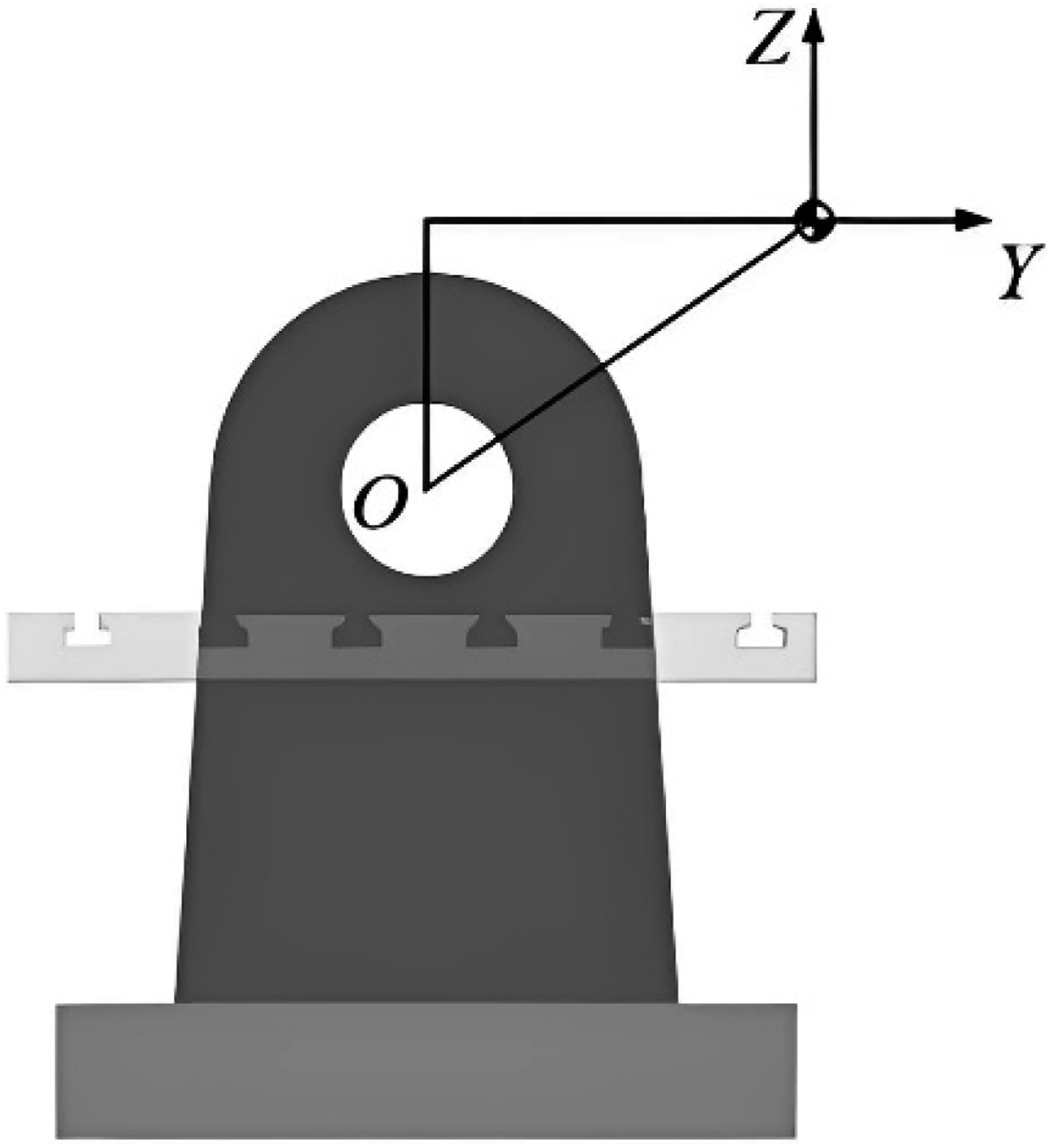
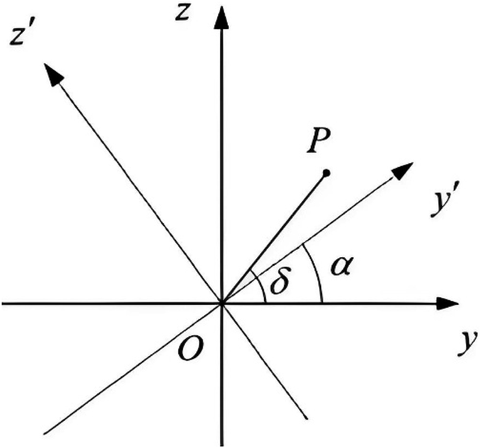
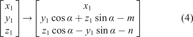
Let the module of the corresponding vector of OP be r, and the angle with the y-axis be δ, then:
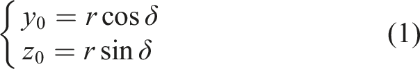
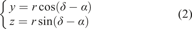
According to formulas (1) and (2), the information can be obtained below:
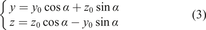
During the rotation of the A-axis, the X-coordinate of any point on the tooling is always kept constant, so when the table rotation angle is α, any point on the tooling P/(x1, y1, z1) has the following transformation relationship:
4. Development of post-processing for specialized machines
Multi-angle surface of the clutch housing will be actually processed when the A-axis will be rotated many times, that is, it is necessary to “find the right” many times, the coordinates of the origin of its processing will be transformed in the formula (4), through the development of the post-processing can be converted to the origin of the coordinates of the output to the NC file, when the operator will be keyed into the machine tool coordinates register, you can avoid manual operation, improve production efficiency, and at the same time, improve production efficiency, and at the same time, the development of special machine post-processing. This avoids manual operation and improves productivity while reducing labor costs. The clutch housing for the development of post-processing is divided into three important stages: first of all, the need for digital construction of the machine tool to determine the size of the stroke, the rotary center position, and other parameters for the development of the simulation and debugging. Secondly, it is necessary to monitor the moving process of the integrated A-axis tooling, and effectively prevent mechanical interference risks in advance. Must enter the post-processor on the A-axis rotation of the machine tool to make reasonable adjustments to the logical order of the movement of the axes. Finally, the establishment of the post-processing tools and machine tool interaction window facilitates the user to the post-processing tools to enter the origin of machining coordinate data, so that the NC file output after the transformation of the origin of the coordinates.
4.1. Simulation machine construction
The vertical machining center equipped with A-axis tooling imported into Machine Builder, set the machine travel, Z-axis drive for the machine spindle, and travel 1000 mm. X, Y-axis drive for the table, the travel is 1600 mm, 650 mm, as shown in Figure 7. IV-axis drive for the rotary tooling, the travel ±110°, with the rotary center O position shown in Figure 5, which is relatively relative to the zero point of the machine tool, Y, Z values were −320 mm, respectively. The values of Y and Z are −320 mm and −640 mm, respectively. Since the clutch housing is processed by a special fixture, the clamping point is fixed. Therefore, the mechanical coordinate value of the clamping origin of the indexing tooling is set to the NC simulation origin point (Lv et al., 2025). On the one hand, the position of the part in the machining simulation is the actual position, so that the simulation results are more intuitive. On the other hand, when programming, the machining origin can be set as the clamping point of the indexing tooling, and the subsequent coordinate conversion can directly call the coordinate value of this point to simplify the calculation process. Simulation machine building.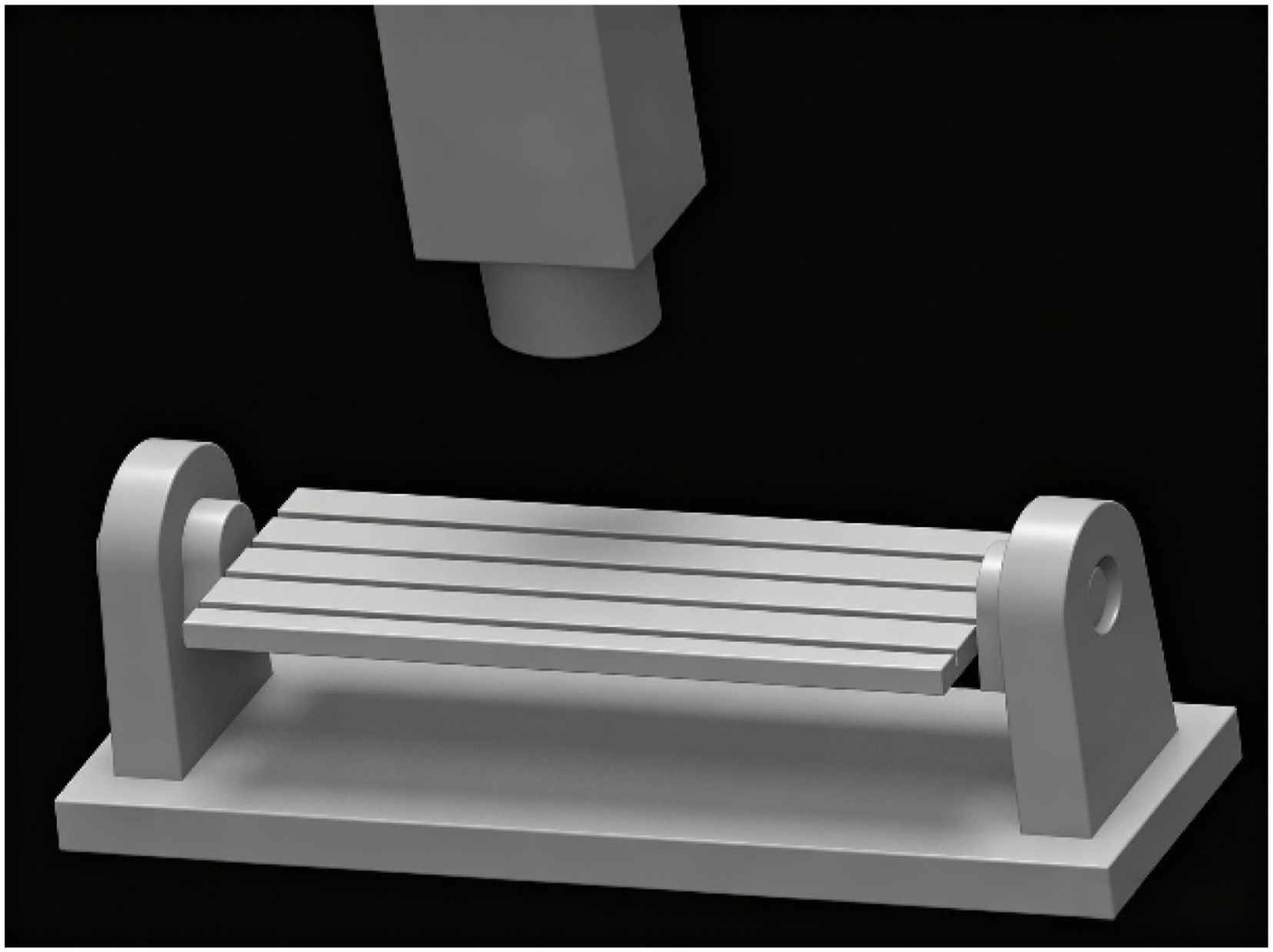
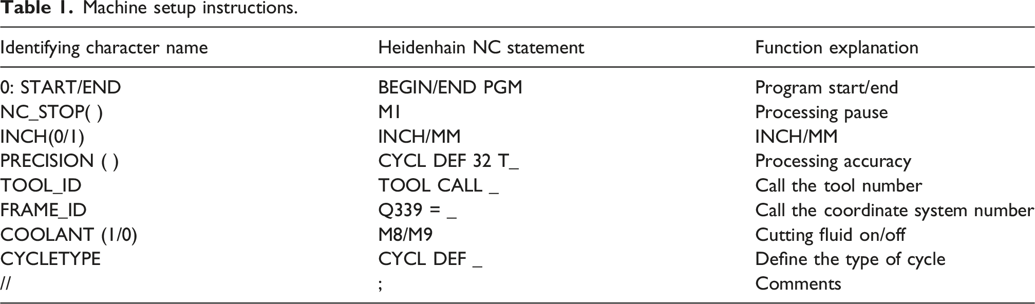
4.2. NC code format conversion
Machine setup instructions.
Tool motion commands.
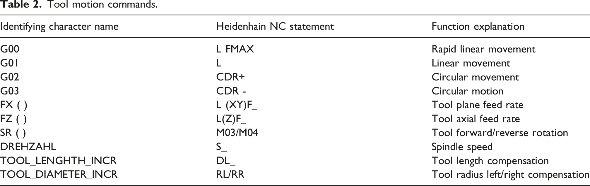
According to Tables 1 and 2, “Format specifications” in the HyperPOST post-processing builder completes the conversion of the tool position code to NC code as shown in Figure 8. Post-processing format conversion.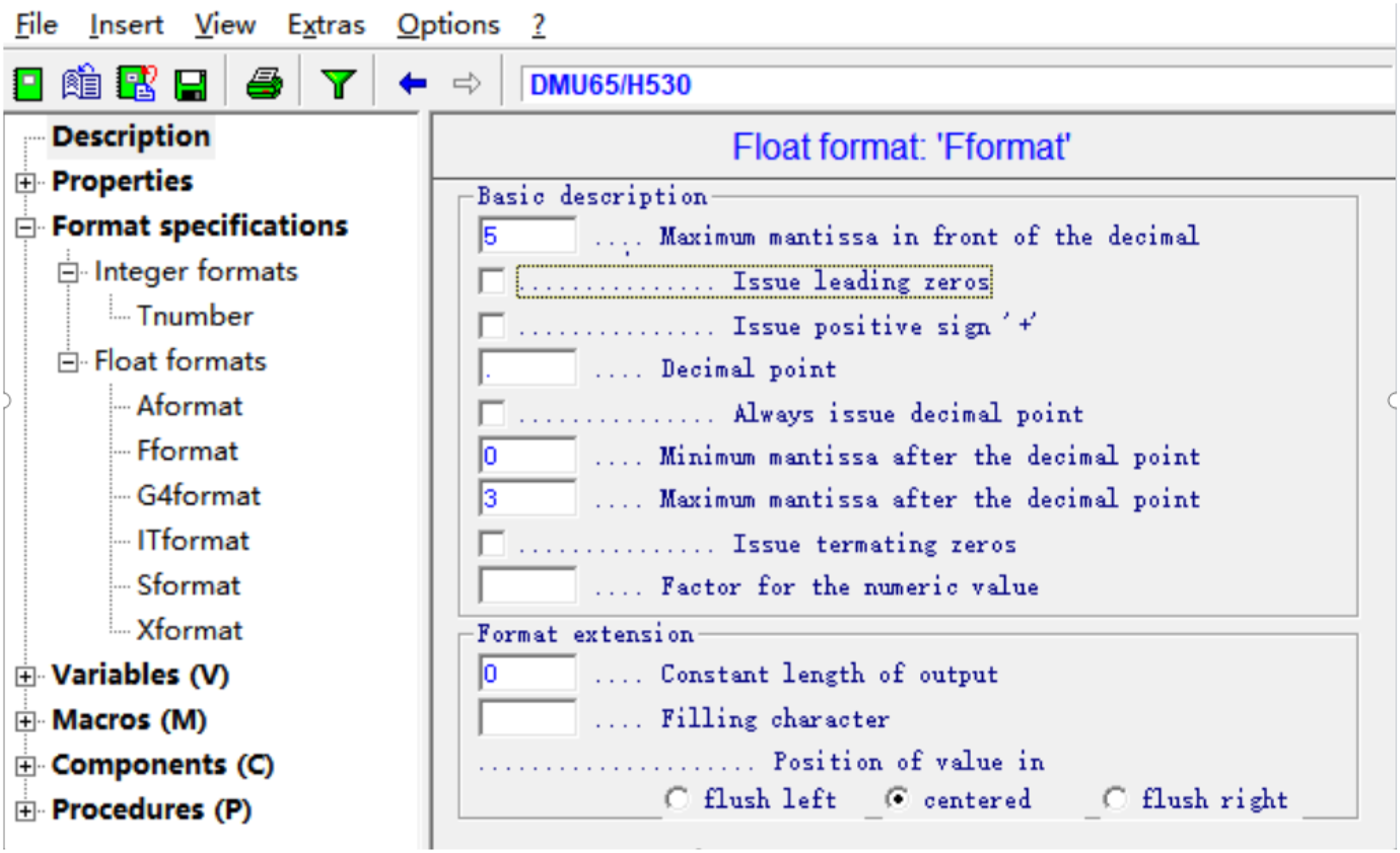
4.3. Interference check and macro-program customization
After the introduction of A-axis tooling in vertical machining centers, the risk of machine interference is bound to increase in the machining process (Zaragoza et al., 2024), especially when it is rotated, and a safe stopping point should be developed for the tool when machining at a variable angle, and the machining instruction should be executed when it is rotated. As fixed-axis cutting is adopted for clutch housing processing, A-axis movement instructions are merely arranged at the initial stage of each working procedure. Without rotation action, the tool can skip returning to the safe position to raise processing efficiency. In response to this problem, the post-processor macro module can be inserted into the logic statement to determine whether the A-axis rotation occurs at the beginning of the work step, and then determine whether the tool returns to the safety point of the instruction output. A macro flowchart is shown in Figure 9. Part of the code is as follows: Program flow chart.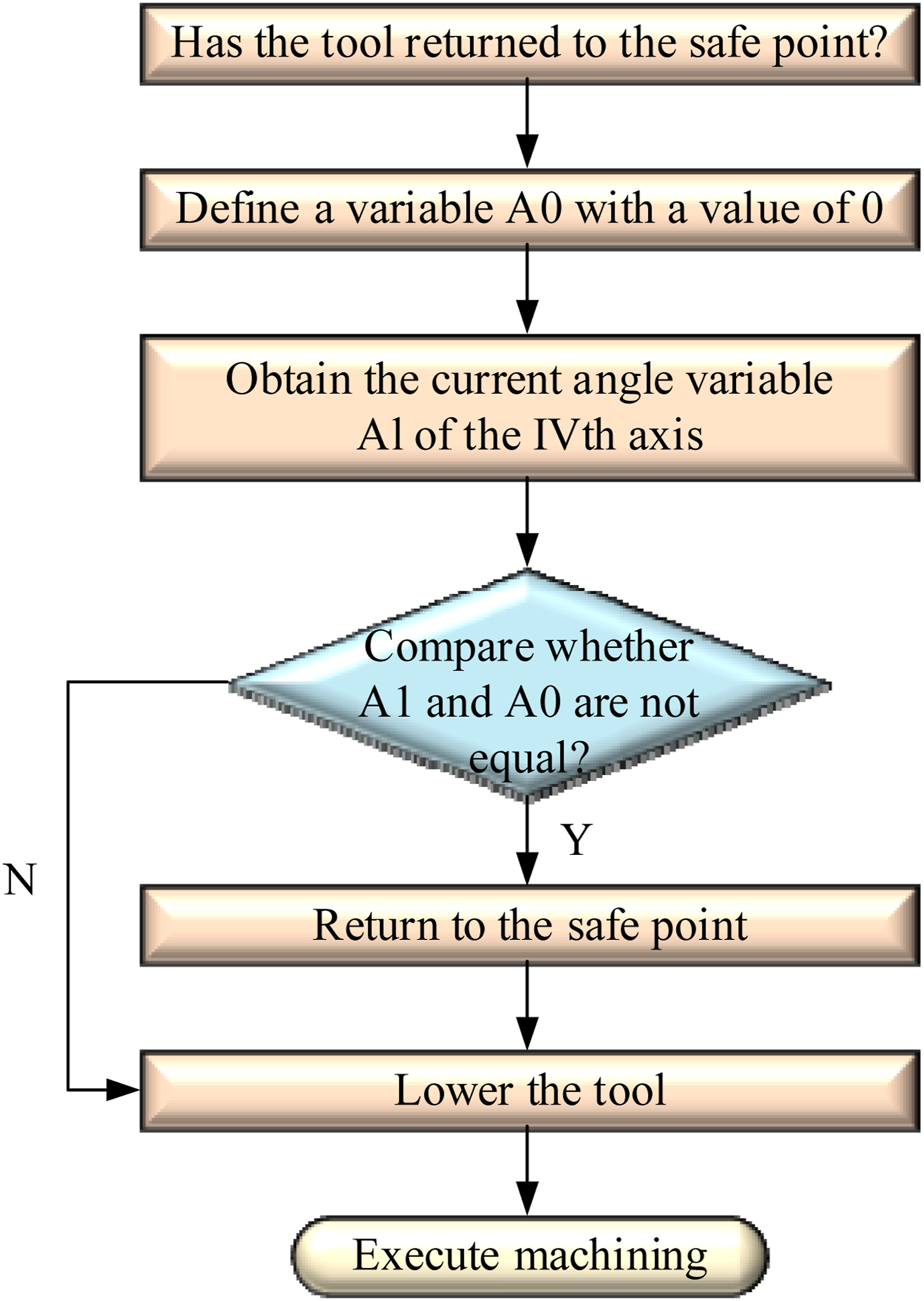
lvf sr1, Current_Angle_A//load the current angle of the A-axis to a floating-point variable (sr1).
lvf sr2, 0//Load the value 0 into another floating-point variable (sr2).
cvf A0, sr2//Copy the contents of sr2 (which has the value 0) into another floating-point variable (A0).
cvf A1, sr1//Copy the contents of sr1 (which stores the current A-axis angle) into another floating-point variable (A1).
call fchck, A0; A1//Call the fchck function and pass A0 and A1 as parameters for checking the angle.
Jz end_of_anglchck//Go back to safe point.
Exec P moveTo #1//Move to predetermined position.
srs sr1, “G28 G91 Z0”//Z-axis move initial reference home position
srs sr2, “G28 X0”//X-axis moves to initial home position
lbl end_of_anglchck//End
5. Machining and verification
The rationality of the special post-processor developed for the clutch housing needs to be further verified: (1) Use HyperMill automatic programming software to edit all machining features of the clutch housing such as the machining surfaces A, B, C, D shown in Figure 1 in turn, set up the machining parameters and cutting dosage of the tool path trajectory obtained after loading the special post-processing machine tool script file will be output to the tool path as NC file Standby. (2) In Vericut simulation software, set up the machine tool machining CNC system and import the machine tool and parts model, set up the machine zero point, tool clamping point, and other parameters, and then import into the NC file for simulation of the clutch housing machining. Several key points need to be noted during the above verification.
Key point 1: Retreating the tool overtravel. When using HyperMill to program the toolpath of the clutch housing, special attention should be paid to the problem of overtraveling of the machine tool in multi-axis machining, that is, when using the indexing tool to adjust the angle of the clutch housing and then machining the D surface, the machine tool A-axis is rotated by 90° At this time, the Z-axis coordinate value of the D surface is extremely large, and it is easy to overtravel the Z-axis travel of the machine tool when retracting the tool (Li et al., 2024). To determine the specific retreat distance, the D surface of a hole in the first A-axis angle of 0° when the mechanical coordinates into the formula (4), resulting in the transformation of the Z-axis coordinates of 743.24 mm, the maximum length of the tool on the surface of the machining D 379 mm, taking into account the Z-axis stroke of the machine tool, the retreat safety plane should be 60 ± 20 mm for a reasonable value.
Key point two: single multi-sequence simulation. Since the machining surface of the clutch housing part contains multiple angles, manual adjustment of the indexing fixture will be inserted between the actual cutting processes, so the simulation needs to be carried out several times in different processes, which is a cumbersome step (Liu et al., 2016). To realize the single multi-sequence simulation, set up multiple stations at the same position on the A-axis tooling, match the corresponding machining coordinate system for each station, place the parts in the correct attitude, and segment the machining commands in the NC file according to each station. The simulation process is shown in Figure 10. Single-station multi-sequence simulation.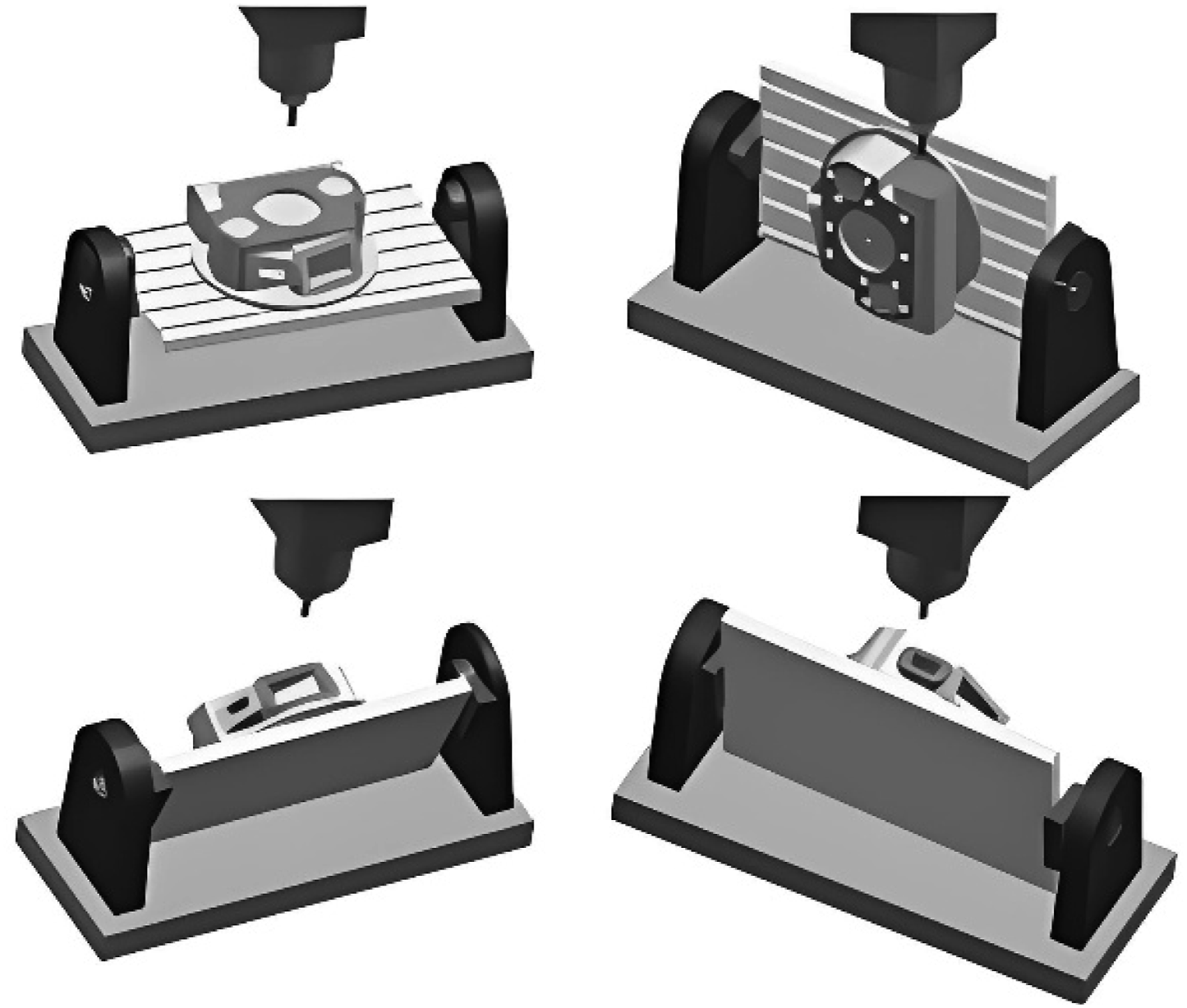
Simulation to verify the safety and correctness of the case, the NC program was entered into the machine tool for CNC machining, and the processing of the clutch housing was completed after the use of three-coordinate machine tools to detect that the size, shape, and position tolerance are in line with the requirements shown in Figure 11. On-site machining and measurement.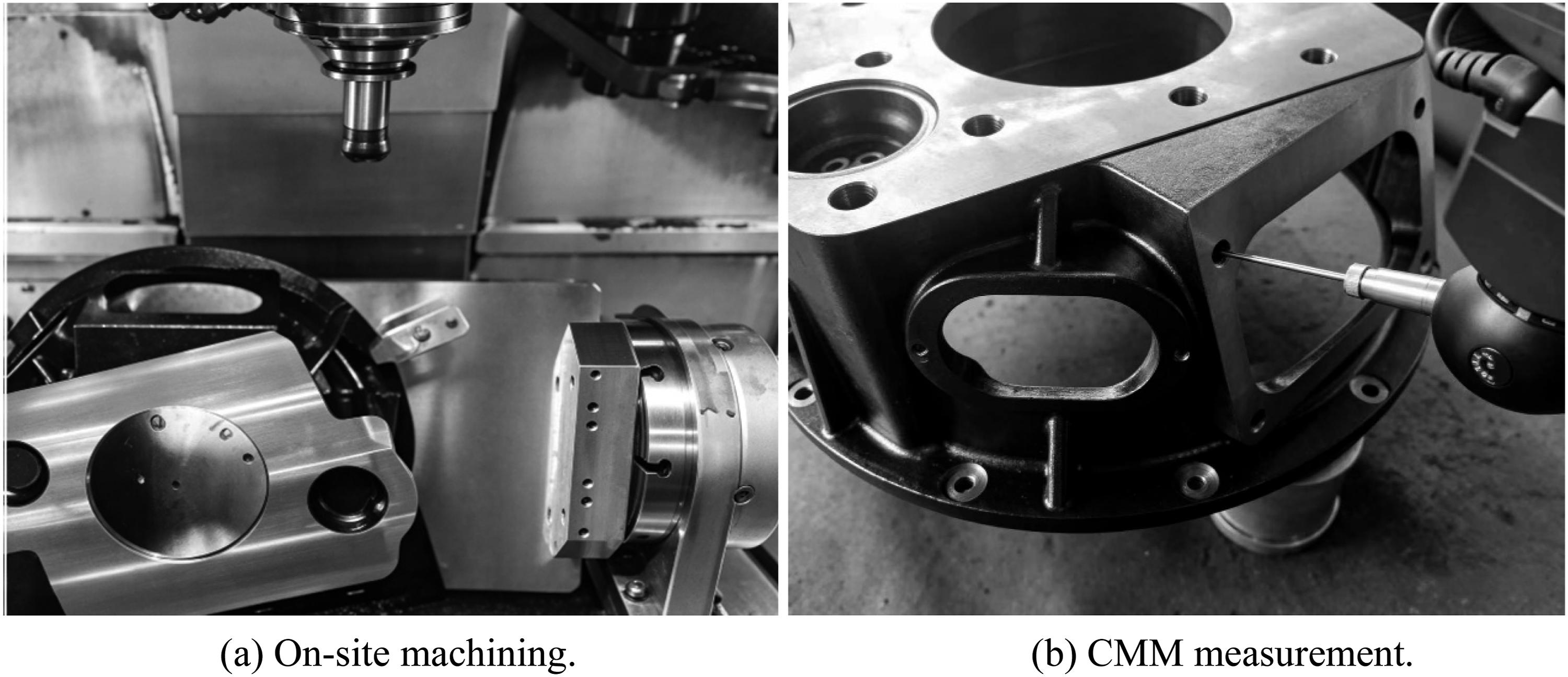
6. Conclusion
In this work, a kinematic model for a three-axis vertical machining center retrofitted with an A-axis indexing fixture is established, deriving the coordinate transformation relationships caused by A-axis rotation. This provides a rigorous theoretical foundation for maintaining a consistent workpiece origin during multi-angle machining. The core pain point addressed is the repeated manual origin re-alignment required after each A-axis rotation when machining multi-angled surfaces of clutch housings on low-cost non-RTCP machine tools, which leads to low efficiency, long setup time and inconsistent machining accuracy. To solve this problem, this paper proposes a novel single-alignment control strategy by integrating kinematic modeling, dedicated post-processor development, and macro-program-based safety control. The developed post-processor automatically calculates and embeds transformed origin coordinates into NC programs, eliminating manual re-alignment and enabling continuous multi-angle machining in a single setup. Compared with the conventional repeated alignment process, the total setup time is reduced, and the dimensional accuracy is controlled, effectively reducing human-induced errors and improving machining consistency. Two key technical challenges, including tool retraction overtravel and single-program multi-sequence simulation, are also identified and resolved. Actual machining and CMM inspection verify that all dimensional and geometric tolerances meet the design requirements, confirming the effectiveness and practicality of the proposed single-alignment control method for non-RTCP modified machine tools. Nevertheless, the proposed method has certain limitations. It assumes ideal machine rigidity and ignores minor geometric and thermal errors, which may degrade accuracy in long-cycle machining. The post-processor is currently tailored for HEIDENHAIN systems, restricting its universality. Future work will incorporate geometric error compensation to enhance precision. A generalized post-processor for mainstream CNC systems will also be developed.
Footnotes
Funding
The authors disclosed receipt of the following financial support for the research, authorship, and/or publication of this article: This research was supported by Shandong Provincial Key Research and Development Program (Grant No. 2024TSGC0920).
Declaration of Conflicting Interests
The authors declared no potential conflicts of interest with respect to the research, authorship, and/or publication of this article.