
Abstract
Due to its high resilience to uncertainties and disturbances, Sliding Mode Control (SMC) is frequently employed in nonlinear systems; however, it suffers from an inherent drawback of chattering, resulting in high-frequency control oscillations, increased actuator wear, and energy inefficiency, which often limit its practical application. This paper presents a practical solution to reduce chattering without altering the fundamental structure of SMC, by introducing an Integral Resonant Control (IRC) loop as a signal-shaping stage that preserves robustness while smoothing switching-induced oscillations. The proposed SMC–IRC approach is experimentally validated on a twin rotor aerodynamic system, a strongly coupled nonlinear MIMO platform that emulates helicopter-like dynamics, and its performance is evaluated under both step and sinusoidal tracking tasks in comparison with conventional SMC and Super-Twisting SMC. The results demonstrate that the proposed method maintains comparable tracking accuracy while significantly reducing chattering and control energy; in sinusoidal tracking, it improves actuator command smoothness and reduces control signal variation, while step-response results confirm reduced mechanical stress with only a slight trade-off in transient speed. Overall, the findings indicate that resonance-based signal shaping provides an effective and actuator-friendly enhancement to SMC, offering a simple, computationally efficient solution suitable for robotic and real-time aerospace applications where hardware protection and smooth control action are critical.
Keywords
1. Introduction
Sliding Mode Control (SMC) is widely used for nonlinear systems due to its robustness against uncertainties and disturbances (Bascetta and Incremona, 2021; Fatemi and Akbarimajd, 2025; Paiva et al., 2019). It ensures accurate tracking by driving system states onto a predefined sliding surface (An et al., 2018; Longfei et al., 2019). However, its main limitation is chattering, caused by high-frequency switching in the control law (Abbasi and Lee, 2018; Lei and Li, 2018). This can lead to actuator wear, excitation of unmodeled dynamics, reduced tracking accuracy, and potential stability issues (Suleiman et al., 2018; Tseng and Chen, 2010; Zhang et al., 2025).
The Twin Rotor Aerodynamic System (TRAS) is a standard benchmark due to its nonlinear, coupled, and sensitive dynamics (Ahmad et al., 2000; I; Gu et al., 2013; NTECO Ltd., 2019). As a result, SMC is widely applied to TRAS, UAVs, and multirotor systems (Yin et al., 2018). Existing approaches include adaptive SMC for nonlinear handling (He et al., 2026; Król, 2024; Kumar et al., 2025; Shen et al., 2025), integral SMC for improved steady-state accuracy (Eltayeb et al., 2022), and terminal SMC for finite-time convergence (Nguyen et al., 2022; Weidong et al., 2015). Despite these advances, effective chattering reduction remains essential for stability and actuator protection (He et al., 2026; Labdai et al., 2020; Zeghlache et al., 2016).
Higher-order sliding mode (HOSM) methods, such as the Super-Twisting (ST-SMC) algorithm, reduce chattering by shifting discontinuities to the derivative of the control signal, resulting in a continuous output (Bkekri et al., 2019; Vijapur et al., 2024; Zhang et al., 2021a; 2021b). While this approach improves smoothness in quad-rotor and TRAS applications (Chen, 2024; Wang and Ji, 2025), its performance can degrade in systems with strong resonant modes or frequency-domain constraints (Zhang et al., 2021a; 2021b). Consequently, achieving a balance between robustness and smoothness still requires intensive gain tuning. Vibration control techniques like Integral Resonant Control (IRC) were originally developed for active damping in flexible cantilever structures and nano-positioning systems (Abdullahi et al., 2014; Díaz et al., 2012; Yoshida et al., 2023). By introducing favorable phase characteristics near resonance, IRC improves damping without compromising low-frequency tracking performance, a synergy successfully demonstrated in precision robotics (Hamza et al., 2026; Omidi and Mahmoodi, 2016; Saeed et al., 2022). However, the use of IRC specifically for chatter mitigation within a Sliding Mode Control (SMC) framework, particularly for coupled MIMO systems like the TRAS, remains largely unexplored. This paper proposes a novel hybrid architecture: SMC–IRC. Building on previous simulation studies of a 3-DOF exoskeleton, this work provides the first experimental validation of the SMC–IRC on a laboratory-scale TRAS platform. The primary objective is to utilize the IRC loop to attenuate high-frequency control components while maintaining robustness and disturbance-rejection properties inherent to SMC.
Three key observations motivate this work. First, while SMC offers fast convergence and robustness, chattering remains a major drawback for nonlinear, cross-coupled systems like the TRAS. Second, higher-order methods like ST-SMC provide smoother signals but require complex tuning and often exhibit residual oscillations. Third, although conventional filters can reduce chattering effects, they frequently compromise tracking performance; in contrast, IRC offers frequency-selective damping, yet its application in nonlinear MIMO sliding mode control systems remains limited. In response, a practical approach, a hybrid SMC–IRC control, is presented in this paper to reduce chattering in SMC while keeping its well-known robustness, and the results are compared with ST-SMC and conventional SMC. The key contributions are: (1) A practical chattering reduction method that preserves SMC robustness by using an Integral Resonant Control (IRC) loop to smooth switching without modifying the core SMC law. (2) Incorporation of resonance-based damping into nonlinear control to suppress high-frequency oscillations while maintaining low-frequency tracking performance. (3) Experimental validation on a TRAS shows that SMC–IRC reduces chattering and control effort while maintaining comparable tracking accuracy against SMC and ST-SMC. (4) Improved actuator performance through smoother control signals, reducing energy use and mechanical stress for real-time applications.
Overall, SMC–IRC offers a simple, effective way to enhance sliding mode control smoothness without sacrificing robustness.
2. Dynamic modeling of the TRAST
A model that emulates a two-axis UAV is a laboratory-scale INTECO TRAS shown in Figure 1. It has two degrees of freedom: yaw and pitch. Aerodynamic forces caused by the propeller result in strong nonlinear coupling between the two axes and make TRAS a standard benchmark in the evaluation of nonlinear control [12]. TRAS experimental platform.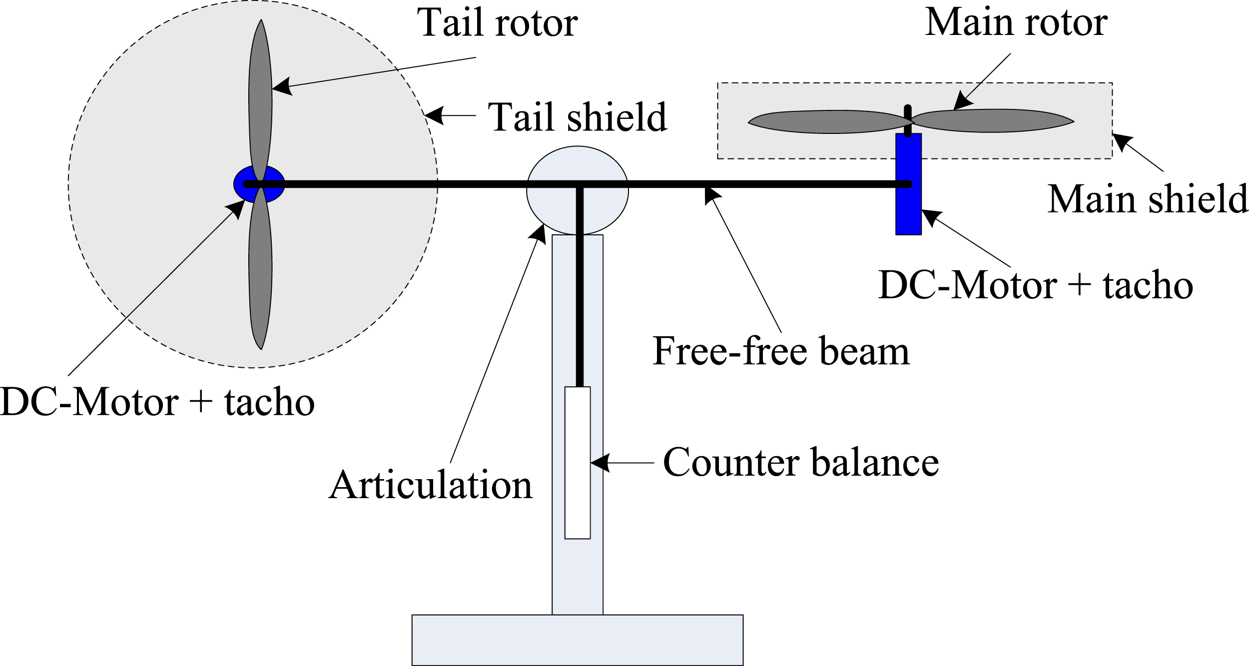
2.1. System configuration
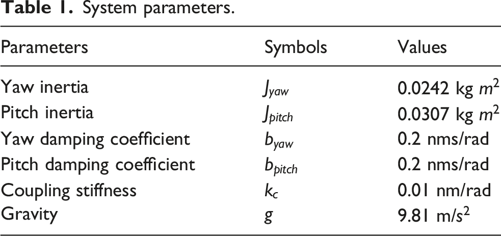
System parameters.
The general nonlinear dynamic equation of the TRAS can be written as
Cross-coupling stiffness causes motion or disturbances in one axis to induce oscillations in the other, creating a resonant interaction that can be amplified by SMC chattering. 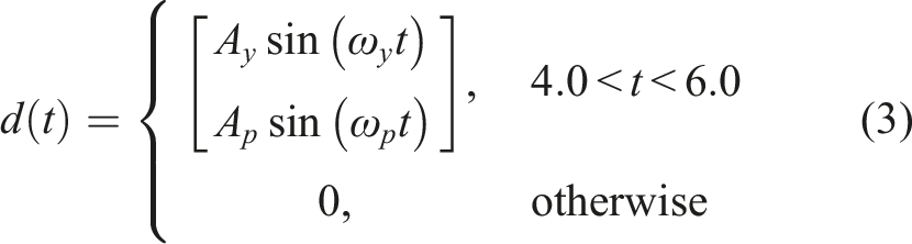
The disturbance injection near the system’s operational frequencies allows assessment of the controller’s ability to remain on the sliding surface while preventing excitation of resonant coupling modes. The symmetric inertia matrix 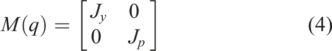
The inertia matrix is diagonal, reflecting the principal rotational inertias of the yaw and pitch axes. This assumption suggests that the inertial cross-axis coupling is relatively weak when compared to other dynamic effects, which is consistent with typical TRAS mass distributions that are decoupled.
Similarly, the damping matrix is defined as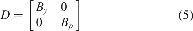
The cross-coupling stiffness matrix is expressed as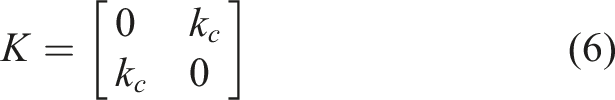
2.2. State-space representation
For control design and stability analysis, the model is converted into a first-order state-space form. Defining the state vector as
The system can be represented as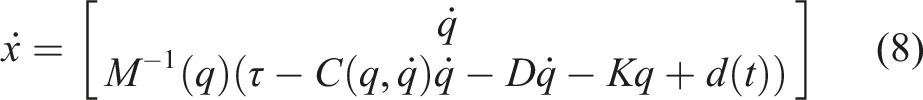
This state-space form is used for the development of the SMC, ST-SMC, and SMC–IRC controllers in the subsequent section.
2.3. Modeling assumptions and limitations
The TRAS model is a reduced-order representation used for control design. The inertia matrix is assumed diagonal, with yaw and pitch inertias, while coupling is mainly captured through the stiffness terms, highlighting inter-axis resonance relevant to chattering analysis.
Coriolis, centrifugal, and higher-order aerodynamic effects are neglected as they have a limited impact under the operating conditions considered. However, the model does not fully capture strong coupling during aggressive maneuvers, actuator nonlinearities, or structural flexibility.
These effects are naturally present in experiments on the real TRAS platform, allowing the controller’s robustness to be evaluated under realistic uncertainties.
3. Control design
This section describes the development of three controllers for the TRAS: conventional SMC, ST-SMC, and the proposed hybrid SMC–IRC.
3.1. Conventional sliding mode control
Let the desired trajectory be 
The sliding surface is selected as
The SMC control input is composed of nominal/continuous and switching components:
The nominal PID control component gives the primary tracking effort based on the error dynamics, while the discontinuous sliding mode term compensates for uncertainties, disturbances, and unmodeled nonlinearities.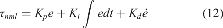
The novelty of this approach is that, in contrast to traditional SMC schemes, where the equivalent control is determined analytically from the plant model, a practical realization is used, where a PID controller is used to approximate the nominal control.
3.2. Super-twisting sliding mode control
The ST-SMC employs the same sliding surface (10) but replaces the discontinuous switching law with a second-order sliding algorithm. The super-twisting control term is given by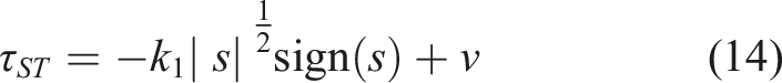


This formulation produces a continuous control signal and reduces chattering compared with classical SMC.
3.3. Integral Resonant Control
Integral Resonant Control (IRC) is introduced as a frequency-selective damping element. Its transfer function is defined as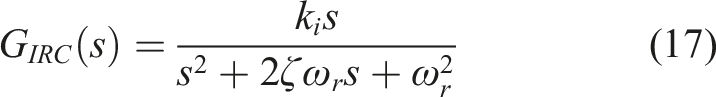
3.3.1. Comparison with filtered SMC
Conventional filtered SMC commonly reduces chattering by passing the discontinuous switching signal through a low-pass filter. A typical second-order low-pass filter can be expressed as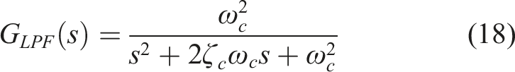
The IRC filter in (17) is not a standard low-pass filter but a resonance-based damping element targeting the dominant TRAS mode. Both filtered SMC and SMC–IRC reduce high-frequency switching effects, but differently: the low-pass filter limits bandwidth, while IRC shapes the control signal through resonance damping.
3.3.2. Frequency-domain interpretation of IRC
Comparing (17) and (18), the IRC has zero DC gain due to zero at the origin, so it does not affect low-frequency control and preserves tracking performance. In contrast, the second-order low-pass filter attenuates high frequencies but also introduces phase lag, which can degrade transient response.
3.4. Hybrid SMC–IRC controller
In the proposed scheme, the SMC switching signal is processed through the IRC filter before being applied to the plant. The block diagram is shown in Figure 2. The hybrid control law is Block diagram of the proposed SMC–IRC controller.
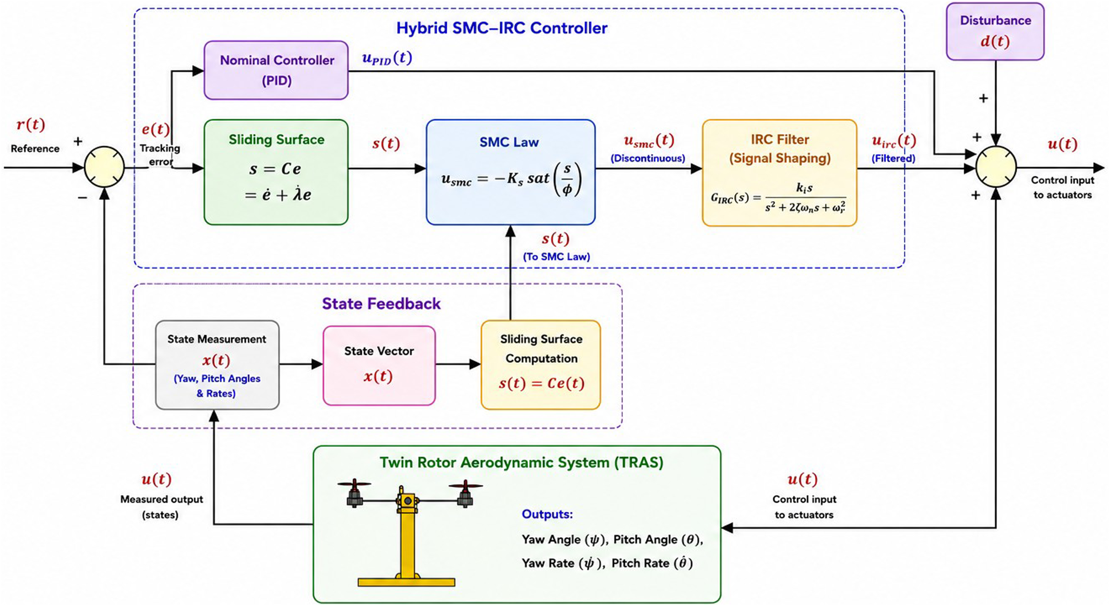
This structure preserves the robustness of SMC while smoothing high-frequency oscillations responsible for chattering.
IRC parameters were tuned to align with the TRAS platform’s primary oscillation bands. The resonant frequency
3.5. Stability analysis
The stability of the proposed SMC–IRC controller is established using Lyapunov theory.
The sliding surface is defined as
Consider the Lyapunov candidate function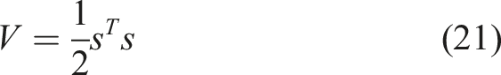
Differentiating with respect to time yields
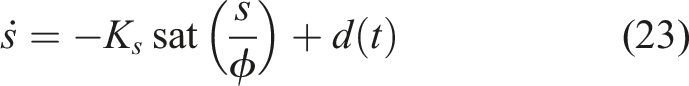
Substituting (23) into (22) gives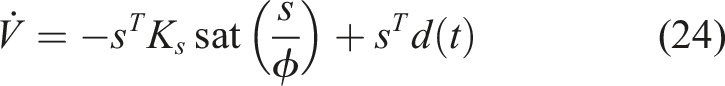


With the IRC filter inserted, the switching signal becomes 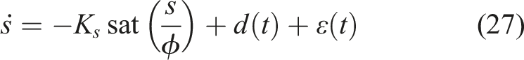
Following the same Lyapunov argument,

Since the reduced-order dynamics on 
Additionally, given the IRC transfer function 
For the proposed IRC, the magnitude response is 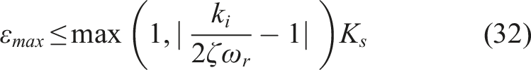
This gives a clear parameter-dependent bound to the perturbation term. The magnitude response of the IRC transfer is a bounded value at all frequencies, as the definition of (17) implies. Thus, the perturbation is such that
The IRC introduces frequency-dependent phase effects, but if the resonant frequency
3.5.1. Effect of IRC dynamics on sliding stability
To further clarify the influence of the IRC loop on system stability, the closed-loop system can be interpreted as an augmented dynamic system that includes the internal IRC states. The IRC transfer function defined in (17) can be written in state-space form as
The augmented closed-loop system, therefore, becomes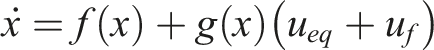

Since the IRC transfer function is strictly proper and internally stable for
Therefore, the IRC loop acts as a stable dynamic compensator that introduces a bounded perturbation into the sliding dynamics without altering the sliding manifold itself. The Lyapunov inequality becomes
Nominal control gains and sliding surface control gains.
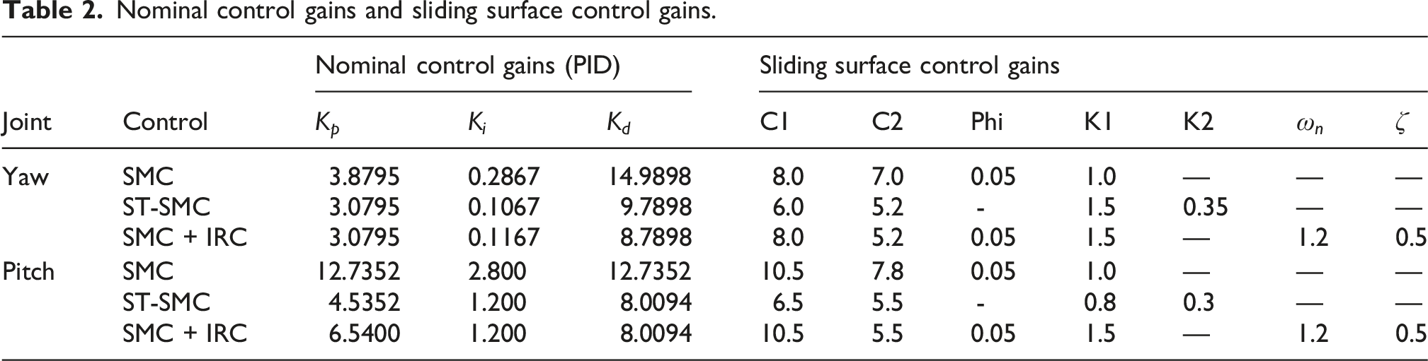
The controller gains reported in Table 2 were independently tuned for each control strategy to achieve stable tracking performance while minimizing excessive control activity. Some gain values appear numerically similar because the controllers were initialized from the same baseline tuning conditions to ensure a fair comparative evaluation on the same TRAS platform. Minor variations were then introduced according to the specific control structure and chattering suppression mechanism of each controller.
4. Experimental setup and performance metrics
This section describes the experimental platform used to validate the proposed control strategy and defines the performance metrics employed for quantitative comparison.
4.1. Experimental setup
Experimental validation was conducted on a 2-DOF TRAS, which replicates helicopter yaw–pitch dynamics using independent main and tail rotors. The complete experimental configuration is illustrated in Figure 3. Experimental setup for implementation of SMC, ST-SMC, and SMC–IRC controllers.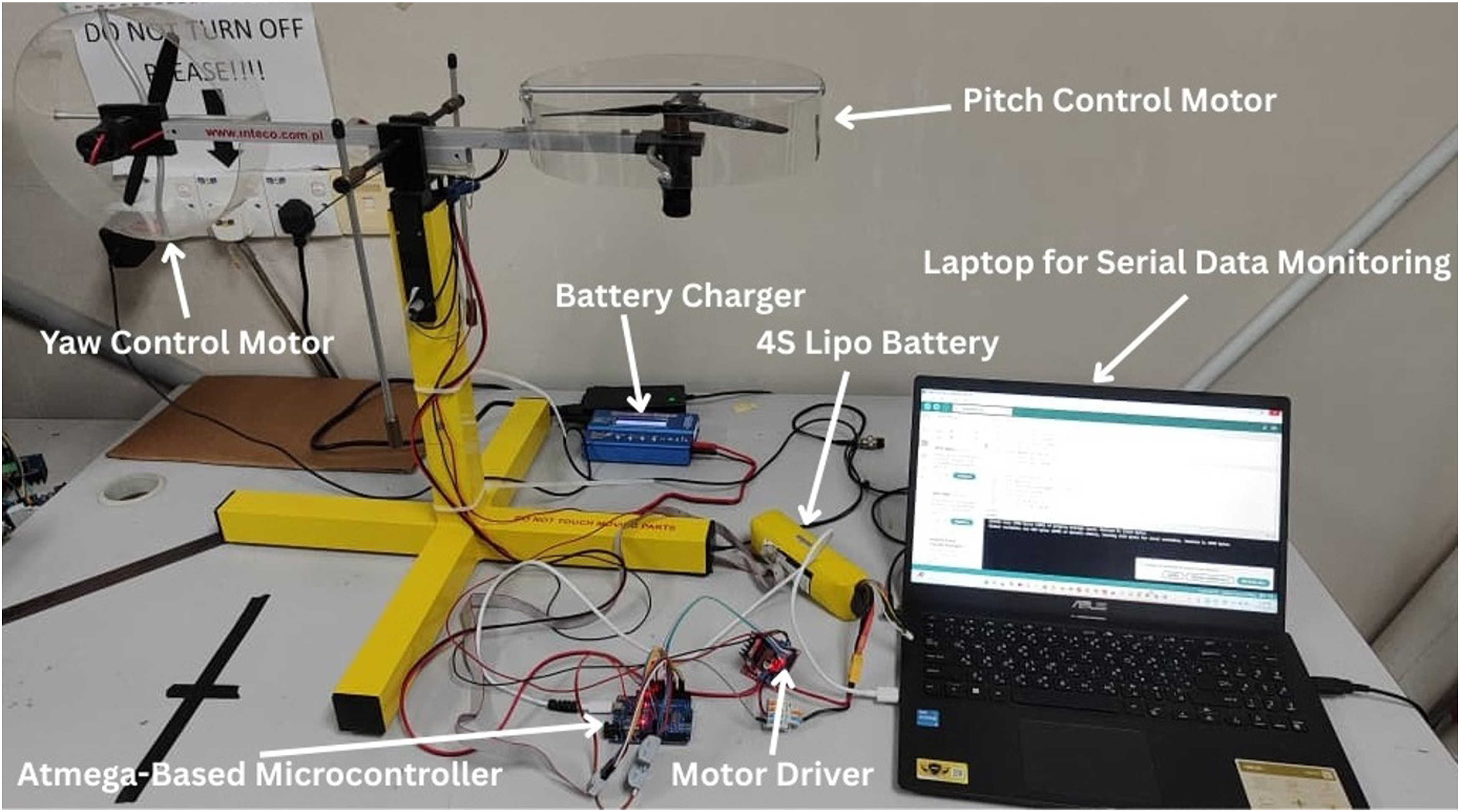
In all experiments, a constant sampling time of 0.002 s (500 Hz) was used to ensure reliable real-time control and data acquisition. Measurement noise, sensor quantization, actuator nonlinearities, and unmodeled disturbances of the TRAS platform, such as encoder resolution limits, motor driver electrical noise, and aerodynamic effects inherently belong to the experimental results. Thus, the findings are realistic operating conditions and display the disturbance-rejection property of the proposed controller.
4.2. Performance metrics
To provide a comprehensive evaluation, three performance indices are used: Root Mean Square Error (RMSE), Chattering Index (CI), and Control Energy Consumption (EN) as in [36].
Tracking accuracy is quantified using the RMSE between the reference trajectory and the measured output: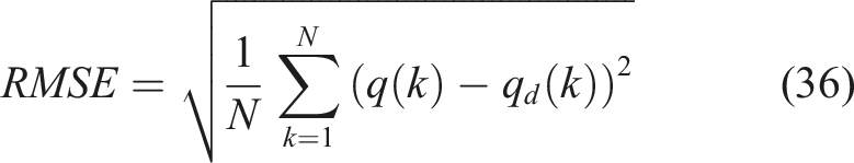
Chattering is evaluated using the CI, which measures the total variation of the control signal:
The control effort is quantified using the energy consumption index: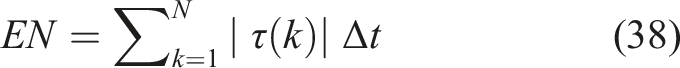
All the experiments were performed with the same initial conditions and controller parameters to be fairly compared. Repeated trials on the TRAS platform showed similar behavior and consistent responses, with only slight differences observed in performance measures. The reported performance indices (RMSE, CI, and EN) were considered over the entire duration of the experiment to represent overall system performance.
5. Results and discussion
This section provides a detailed comparison of three control strategies: SMC, ST-SMC, and the proposed SMC–IRC. The comparison is based on regulating a step input and tracking a sinusoidal trajectory.
5.1. Simulation results
The simulation studies were performed using the TRAS model and used to establish baseline performance trends under idealized conditions before hardware validation.
5.1.1. Step-input tracking performance
Figure 4 presents the yaw and pitch step responses for all three controllers. In each case, the target set-points are reached, confirming that the closed-loop system achieves stabilization in both channels. The transient characteristics, however, reveal notable differences. The conventional SMC and ST-SMC typically deliver faster rise times, but this rapid convergence is accompanied by overshoot and oscillatory settling. Within the TRAS platform, such behavior is expected, as aggressive control action in one axis injects coupling energy into the other, producing small oscillatory exchanges between yaw and pitch. By contrast, the proposed SMC–IRC exhibits a more damped and controlled transient. Importantly, the IRC does not diminish the low-frequency authority required to reach the set-point; rather, it reshapes the switching-induced high-frequency components, yielding a response that is less aggressive in terms of control activity. The proposed SMC–IRC hybrid is different from filtered SMC in that IRC is implemented in the control loop as a dynamic compensator and not used as an external smoothing filter. This allows the reduction of chattering and the dynamic shaping of performance at the same time. Step tracking performance comparison for (a) yaw angle (rad) and (b) pitch angle (rad) under SMC, ST-SMC, and SMC–IRC.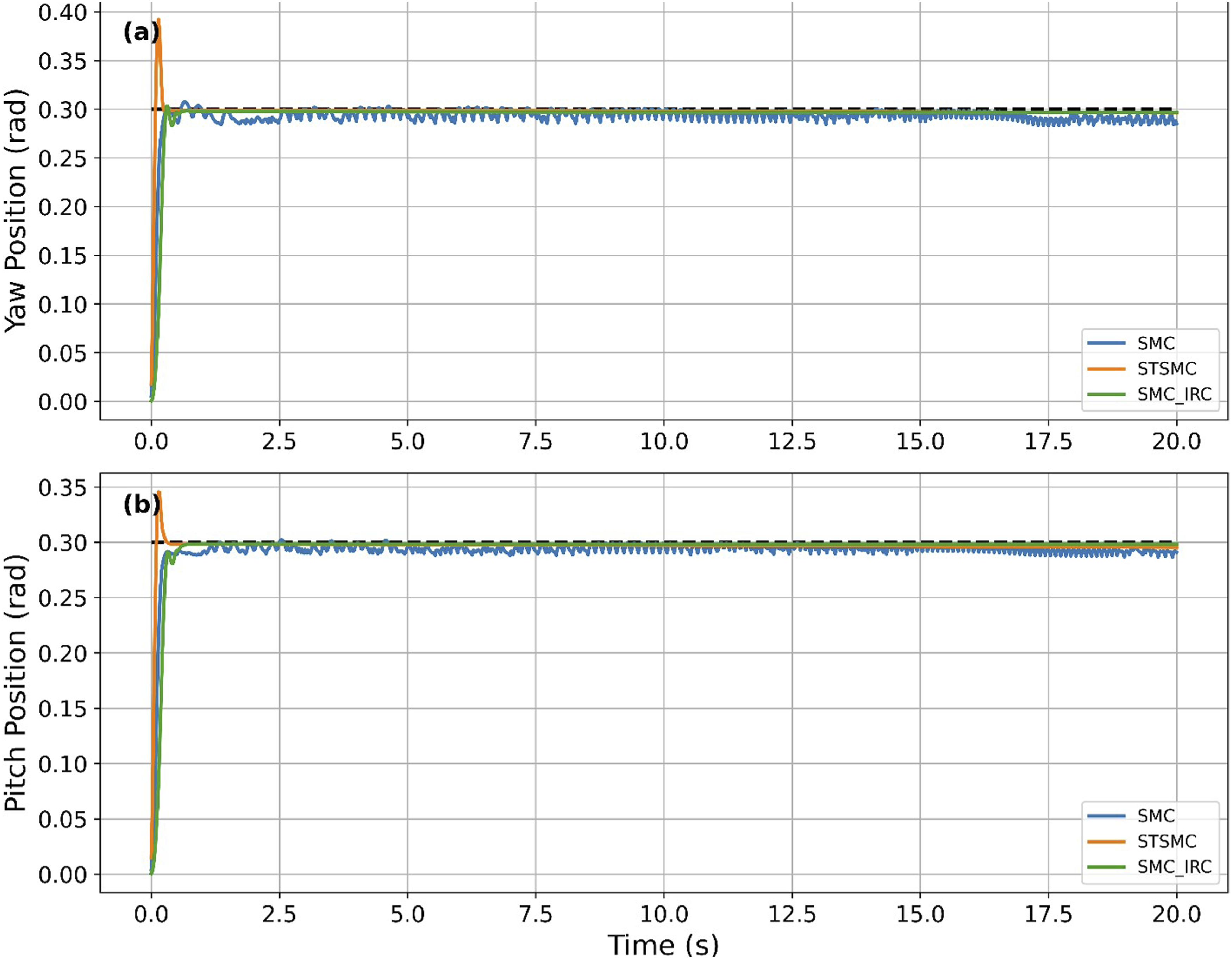
5.1.2. Sinusoidal tracking performance
Figure 5 demonstrates the sinusoidal tracking performance that is more difficult to handle than the step input, since it should be controlled continuously without phase lag. The proposed SMC–IRC has good phase and amplitude tracking, but the conventional SMC and ST-SMC have small oscillations. The reason is that sinusoidal inputs never stop driving the system, and high-frequency switching can always inject unwanted energy into resonant and coupling dynamics. The IRC is a frequency-selective damping mechanism that suppresses such components but still achieves the necessary control action. In contrast to step responses, sinusoidal tracking displays behavior in the frequency domain and resonance behavior. Even though ST-SMC lowers the discontinuities, high-frequency energy is still added. IRC dampens these elements, leading to smoother and more precise tracking. Sinusoidal tracking performance comparison for (a) yaw angle (rad) and (b) pitch angle (rad) under SMC, ST-SMC, and SMC–IRC.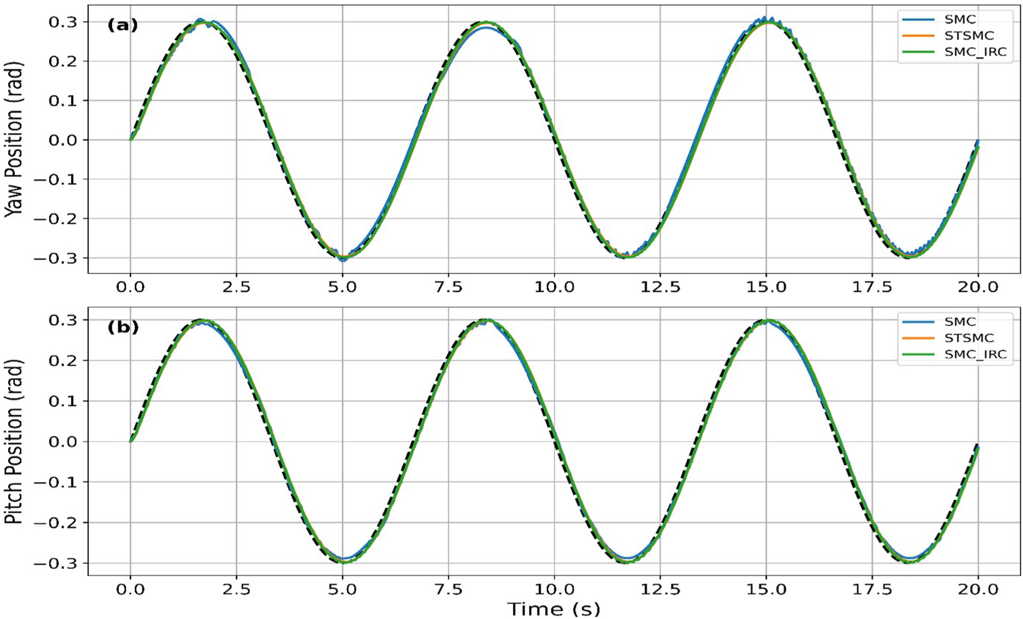
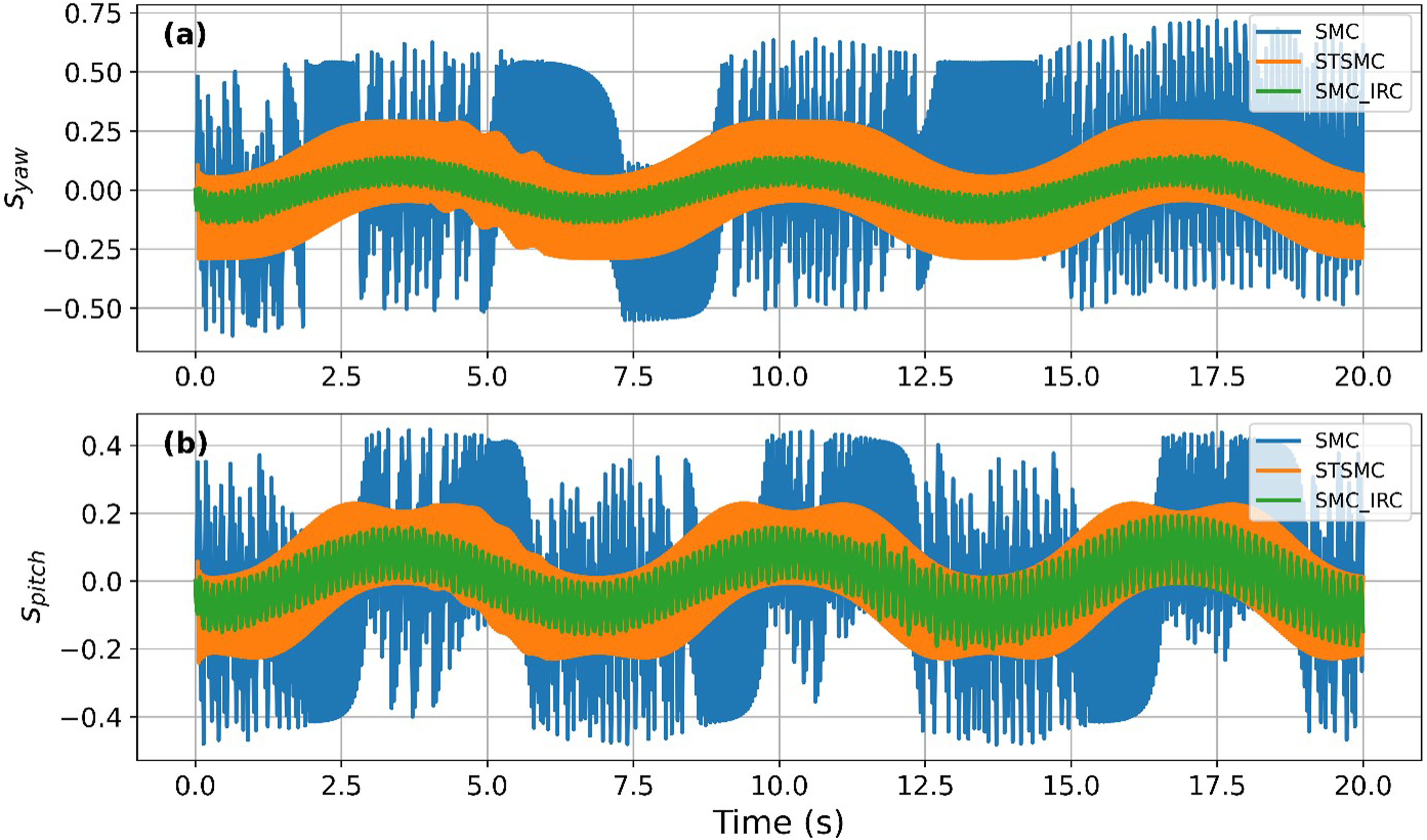
5.1.3. Sliding surface convergence
Figures 6 and 7 depict the behavior of the sliding surface in response to step and sinusoidal action in the yaw and pitch. The main difference between conventional SMC and ST-SMC is that the former displays pronounced oscillations around the sliding surface because of the discontinuous switching, whereas the latter reduces these oscillations. The proposed SMC–IRC gives the smoothest convergence to s = 0. This leads to a smoother actuator torque, lower coupling oscillations between yaw and pitch, greater dynamic performance, and enhanced hardware safety, which proves the appropriateness of SMC–IRC to a practical application. Sliding surface convergence for all controllers under step input (simulation). Sliding surface convergence for all controllers under sinusoidal input (simulation).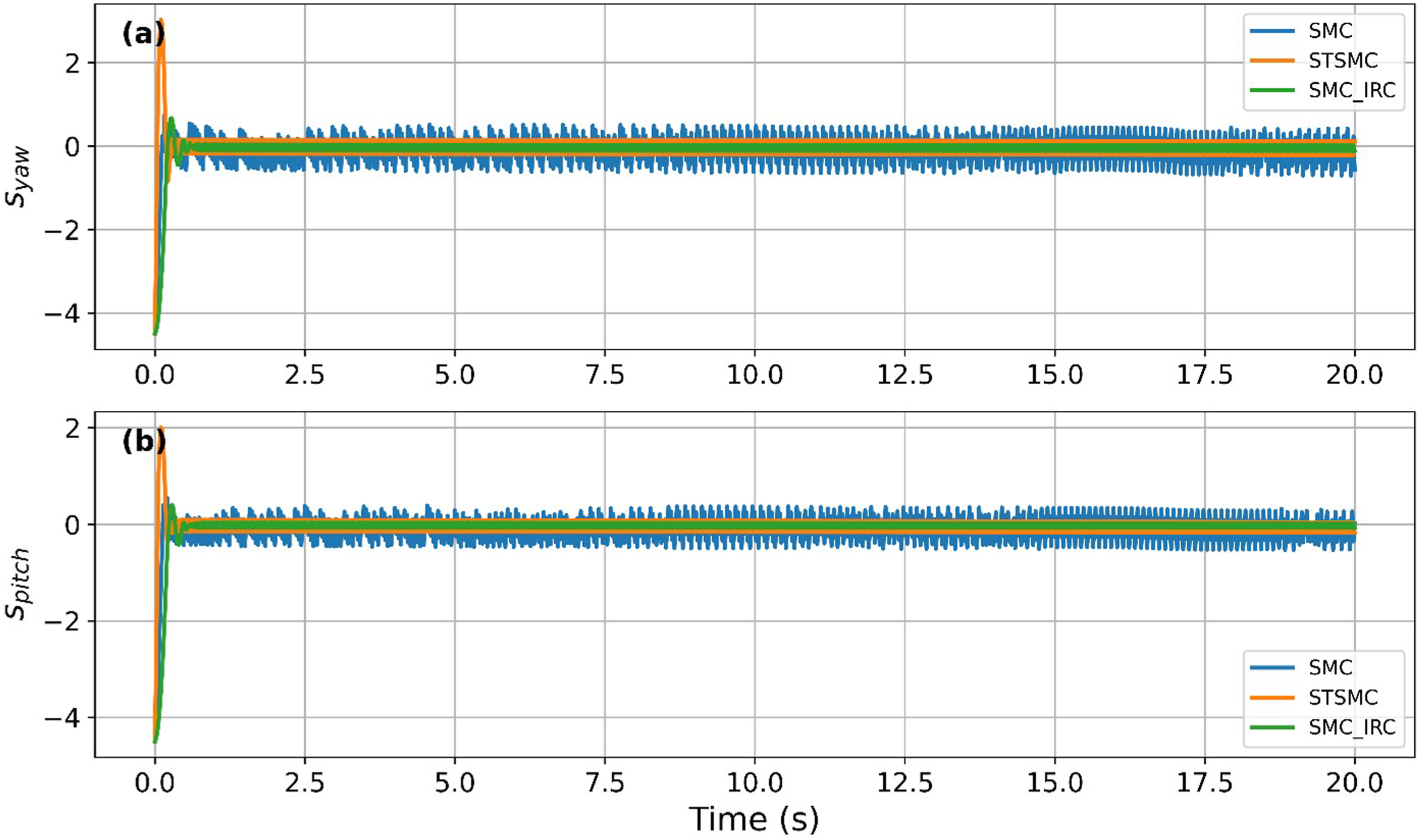
5.2. Experimental results
The simulation trends in the real conditions, such as sensor noise, actuator saturation, and aerodynamic uncertainties, are confirmed by the experimental results. All real-time experiments made use of a fixed sampling time of 0.002 s (500 Hz), which was chosen to suit the TRAS dynamics and controller calculation requirements and minimize the effects of discretization. The inherent noise and measurement disturbances of the real world are included in the results and give a realistic measure of controller performance.
5.2.1. Step-input tracking
Figure 8 compares experimental step responses for yaw and pitch. Although all controllers reach their set-points, standard SMC and ST-SMC exhibit faster rise times at the cost of high overshoot and oscillations. Conversely, the SMC–IRC provides a damped, stable response without abrupt excitation. Real-world hardware factors, like motor dead-zones and noise, exacerbate switching issues, making the SMC–IRC’s reduced switching activity more critical in practice than in simulation. Experimental step tracking performance for yaw angle (rad) and pitch angle (rad).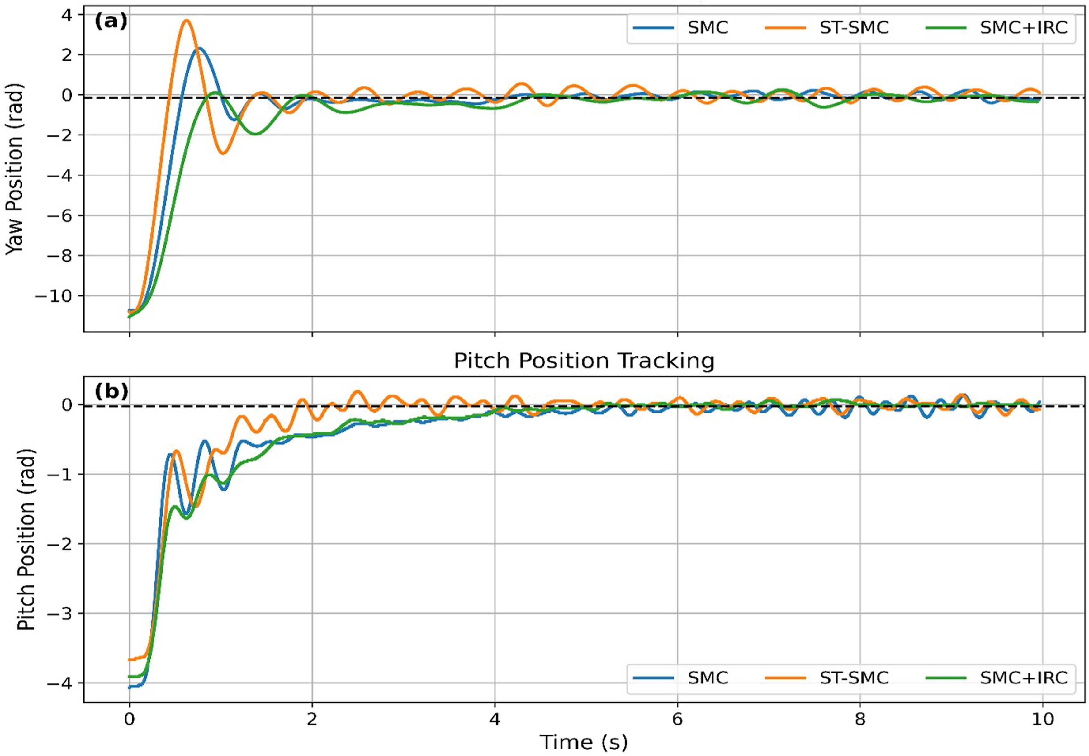
5.2.2. Sinusoidal tracking
Figure 9 shows the experimental sinusoidal tracking results. The proposed SMC–IRC tracks the reference more closely, while SMC and ST-SMC exhibit phase lag and small oscillations. Quantitatively, SMC–IRC achieves the lowest cumulative error (RMSE_sum = 0.0264), outperforming ST-SMC (0.0297) and SMC (0.0278). The IRC loop reduces high-frequency switching effects, preventing unwanted oscillations in the control signal. This leads to smoother response, reduced vibration, and improved tracking performance in periodic motion tasks. Experimental sinusoidal tracking performance for yaw angle (rad) and pitch angle (rad).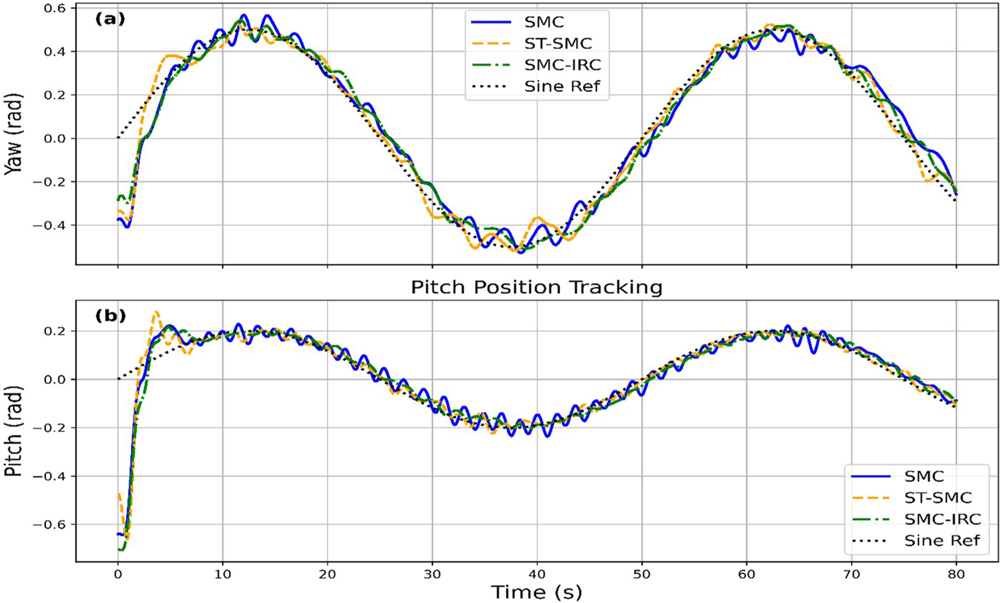
5.2.3. Experimental control signals
Figures 10 and 11 display experimental control torques. Conventional SMC exhibits a dense high-frequency oscillatory control signal, which may increase actuator stress and reduce hardware reliability. ST-SMC provides some improvement but still shows residual oscillatory behavior. In contrast, the SMC–IRC produces the smoothest control torque, indicating that the IRC loop effectively reshapes the discontinuous control signal and substantially reduces actuator stress. Control signals under step input for SMC, ST-SMC, and SMC–IRC (Nm). Control signals under sinusoidal input for SMC, ST-SMC, and SMC–IRC (Nm).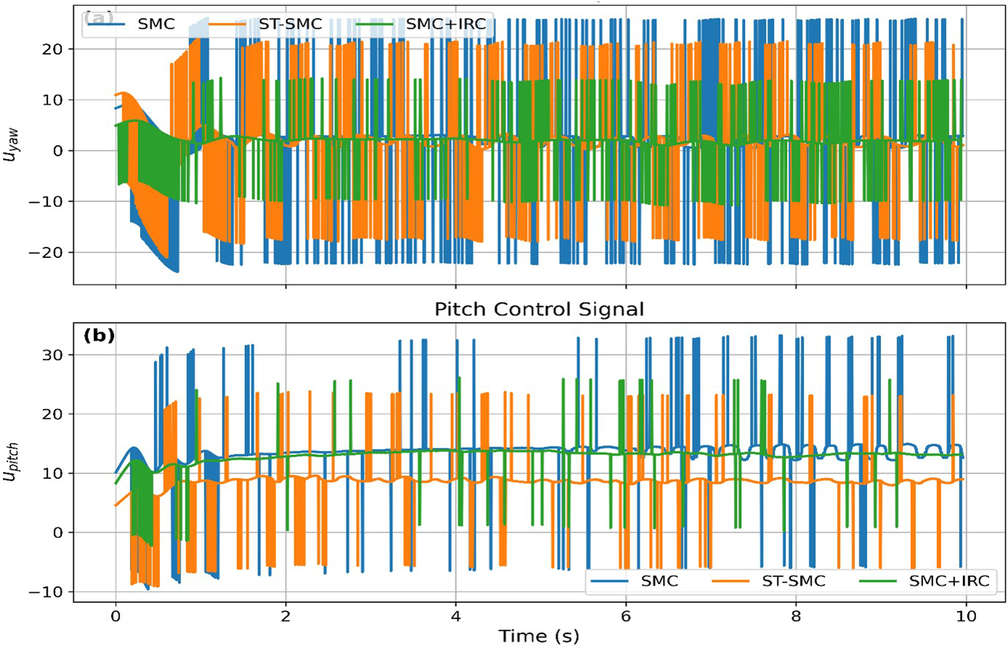
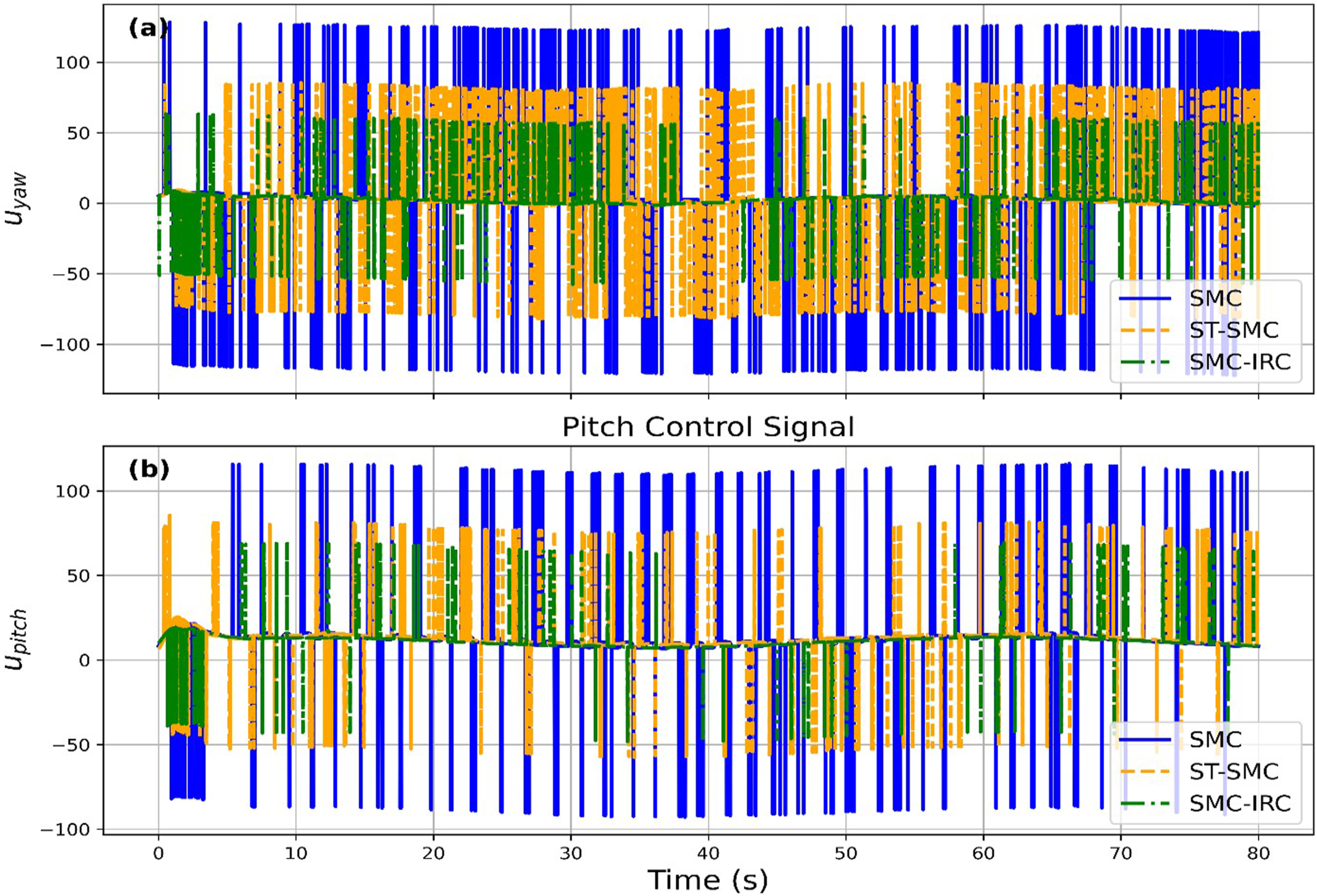
In practice, this smoothness is vital for reliability. Unlike simulation, real-world chattering causes motor overheating, driver stress, mechanical wear from torque ripple, and battery drain. By eliminating these issues, the SMC–IRC ensures superior stability and protects electromechanical components.
5.2.4. Sliding surface behavior
Figure 12 (step response) and 13 (sine response) illustrate the experimental convergence of the sliding surface. For robust sliding operation, the system states are expected to reach s = 0 and remain in close proximity despite external disturbances. The SMC–IRC demonstrates a stable reaching phase with smoother convergence, confirming that the incorporation of IRC does not compromise reachability but effectively attenuates oscillatory motion around the manifold. Sliding surface convergence under step input.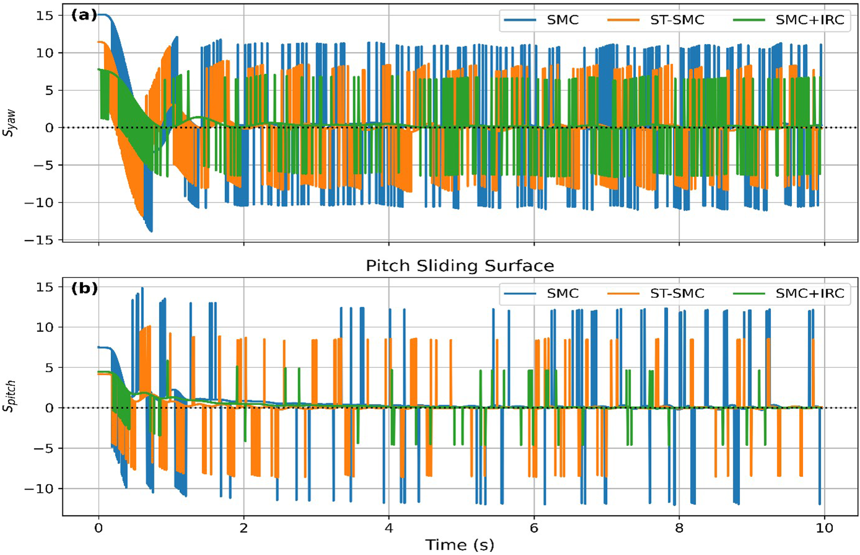
From an engineering standpoint, a smoother sliding surface translates into fewer control reversals and reduced high-frequency mechanical vibration. This observation not only substantiates the stability arguments but also highlights the actuator protection benefits, reinforcing the practical value of resonance-based damping in sliding mode control (Figure 13). Sliding surface convergence under sinusoidal input (experimental).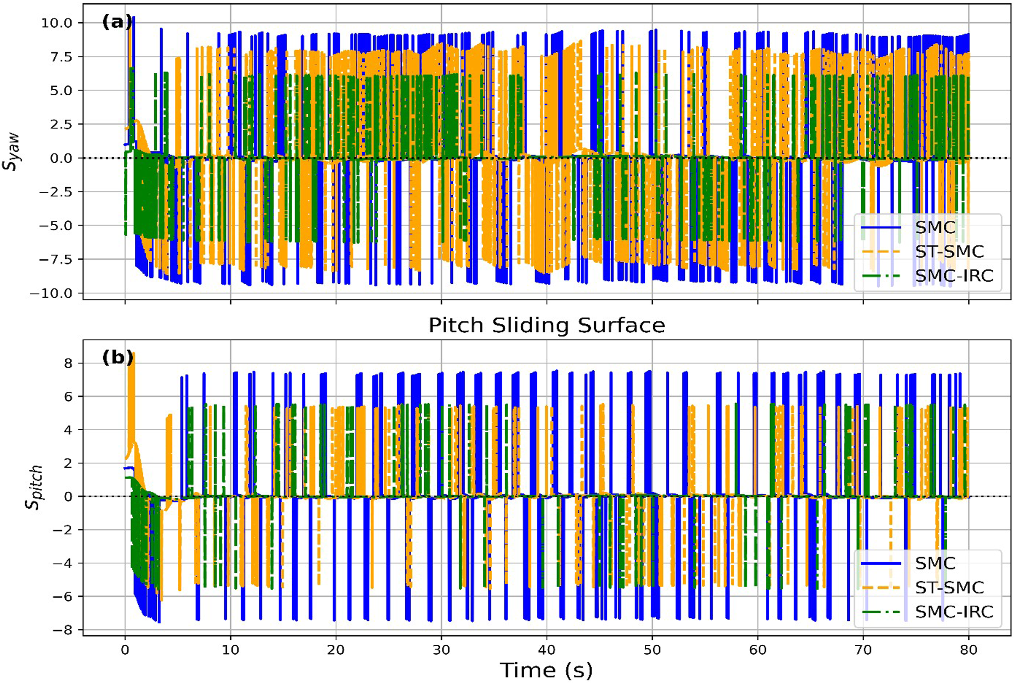
5.2.5. Quantitative performance comparison and discussion
Performance Metrics (Step vs Sine Wave).
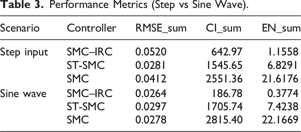
Experimental results confirm these trends. For sinusoidal tracking, the SMC–IRC reduces yaw-axis chattering by 69.5% (1410 to 430 Nm/s) and pitch-axis chattering by 67.7% (930 to 300 Nm/s). Across all inputs, chattering reduction remains above 50%, directly translating to smoother commands, lower mechanical stress, and reduced motor thermal loading. While the ST-SMC offers high transient accuracy, it is associated with excessive control energy consumption and high switching activity. In contrast, the proposed SMC–IRC approach provides a more balanced control strategy by permitting limited transient aggressiveness in exchange for substantially improved reliability, robustness, and energy efficiency. This trade-off is essential for real-world hardware longevity.
These findings indicate that the proposed controller achieves a balanced trade-off between tracking accuracy and control smoothness. The reduction in CI and EN directly translates to decreased actuator stress and improved operational efficiency, which are critical for real-world aerospace and robotic applications.
6. Conclusion
This paper presents a hybrid SMC–IRC technique that effectively mitigates chattering in nonlinear systems by applying resonance-based damping to the control signal. Unlike traditional methods, this approach preserves the robustness and disturbance rejection of Sliding Mode Control without modifying the switching law itself. Experimental validation on a TRAS demonstrates that the SMC–IRC reduces the Chattering Index by over 65% and decreases control energy by an order of magnitude compared to conventional and Super-Twisting SMC. While the increased damping introduces a slight trade-off in transient RMSE for step responses, the resulting control action is significantly smoother, drastically reducing mechanical and thermal stress on the actuators. The proposed integration of frequency-domain resonance damping with nonlinear robust control achieves accurate tracking while enhancing reliability and energy efficiency, making it well-suited for aerospace, robotic, and mechatronic applications.
6.1. Future work
Future directions will examine the proposed SMC-IRC controller in the presence of noise by introducing measurement noise and uncertainties to both simulations and experiments. To test the impact of sensor noise on chattering and control performance, sensor noise such as band-limited Gaussian noise will be added to the measured states.
Both time and frequency domains of the interaction between IRC and noise will be analyzed with focus on noise attenuation, control energy, and potential amplification around the resonance frequency
Footnotes
Acknowledgments
The authors extend their appreciation to Prince Sattam bin Abdulaziz University for funding this research work through the project number PSAU/2025/01/32871.
Funding
The authors extend their appreciation to Prince Sattam bin Abdulaziz University for funding this research work through the project number (PSAU/2025/01/32871).
Declaration of conflicting interests
The authors declared no potential conflicts of interest with respect to the research, authorship, and/or publication of this article.