






Abstract
A plane problem for a poled transversely isotropic piezoelectric plane cut along two equal collinear straight cracks is considered. It is assumed that the electrical yielding occurs at the continuations of the cracks due to the applied mechanical and electrical loadings. We model these crack continuations as the zones with constant cohesive saturation limit electrical displacement. The Stroh formalism and a complex variable technique are adopted to obtain the analytic solution of the problem. Closed-form expressions are derived for the developed saturation zone length, the crack opening displacement, the crack opening potential drop, the stress intensity factors, and the energy release rate. A qualitative numerical case study is presented for ceramics PZT-4, PZT-5H, and BaTiO3 to study the effects of various parameters as follows: developed saturation zone length and prescribed load, stress intensity factor, energy release rate, and crack opening displacement on crack growth resistance. The energy release rate and the stress intensity factor variations are investigated with respect to the inter-crack distance. The results obtained are presented graphically and discussed.
Keywords
1. Introduction
Piezoelectric ceramics have proved their wide utility as sensors, actuator, or transducers in hi-tech instruments. Because of their brittle characteristics the fracture study of such materials has drawn the attention of researchers. A lot of crack problems have been investigated since the 1990s. More recently multisite crack problems have also been addressed.
Multi-cack damage problems being more often encountered in real life situation have attracted the attention of various research communities. While a lot of work has been done on single crack problems in piezoelectric media [1–4], comparatively less work is reported for two or more cracks weakening a piezoelectric plate/strip. Examples are as follows: the generalized 2-D problems in piezoelectric media with collinear cracks based on Stroh formalism and the exact electric boundary conditions on the crack faces [5]; the problem of two equal collinear cracks situated normal to the strip boundaries in an infinitely long piezoelectric strip addressed by using the Fourier series method [6]; a closed-form solution for the anti-plane mechanical and the in-plane electric and magnetic field for two collinear cracks in a magneto-electro-elastic layer of finite thickness under the condition of permeable crack faces using the integral transform method [7]; the problem of two collinear unequal cracks in a piezoelectric material subjected to mode-I loading by a new approach of real fundamental solutions [8].
The strip-yield models for piezoelectric ceramics [9] was started by considering a strip electric saturation model for a finite crack perpendicular or parallel to the poling axis weakening an infinite poled piezoelectric ceramics medium with electric polarization reaching a saturation limit along a line segment in front of the crack. While Wang [3] gave a fully anisotropic analysis of the strip electric saturation model proposed in Gao et al. [9].
Only a small amount of work has been reported for mechanical and electric yielding of a cracked piezoelectric media. The first one to propose a strip-electric saturation and mechanical yield model for mode-III interface crack for piezoelectric material was Shen et al. [10]. Their work was further extended by Bhargava et al. [11] for a cracked piezoelectric plate. An electrical and mechanical yield zone problem for a crack in a thin ductile layer between two piezoelectric materials under remote electromechanical loading was given in Loboda et al. [12]. More recently, we [13] have given a strip-saturation model for a piezoelectric plane weakened by two collinear cracks with coalesced interior zones.
The multiple-crack problems for piezoelectric ceramics considered until now have not yet addressed the crack opening arrest problem. The present work addresses this paucity. In section 2, the fundamental formulation and solution methodology are presented, which is recapitulated from Gao et al. [14]. Section 4 illustrates the solution of the physical problem stated in section 3, for a poled transversely isotropic piezoelectric plane weakened by two collinear equal straight cracks. In section 5, the analytical closed-form expressions are derived for fracture parameters such as stress intensity factor (SIF), saturation zone length, crack opening displacement (COD), crack opening potential drop (COP), and energy release rate (ERR). A qualitative numerical case study is presented in section 6 for ceramics PZT-4, PZT-5H, and BaTiO3 to study the effects of various fracture parameters such as developed saturation zone length and prescribed load, SIF, ERR, COD, and COP on crack growth resistance. The ERR and SIF variations are investigated with respect to the inter-crack distance.
2. Fundamental formulation and solution methodology
As are well-known, in a rectangular coordinate system, xi(i = 1, 2, 3), the basic equations for stress components, σij, and electric displacement component, Di, (i,j = 1, 2, 3), may be expressed as follows: the constitutive equations are

tradient equations are

and the equilibrium equations for stresses and electric displacement in the absence of body force and electric charge, respectively, can be written as

where ui, φ, γij, and Ei denotes displacement, the electric potential, the strain, and the electric field, respectively. cijkl, eijk, and εij stand for the elastic constants, the piezoelectric constants, and the dielectric constants, respectively.
The methodology presented here is recapitulated from Gao et al. [14] to make the paper self-sufficient for the reader.
For a two-dimensional problem all the field variables depend on x1 and x2 and are independent of x3. Therefore, we introduce a generalized displacement vector, u, from Barnett et al. [15] as

where superscript, ‘T’, denotes the transpose of the matrix, f (x1 + px2), is an analytic function, p is a complex number, and a is a constant four element column vector. Equations (1)–(3) satisfy equation (4) for an arbitrary f (x1 + px2) if

which has a non-trivial solution only if

Here the matrices W, R, and Q are given by

Let the eight roots of equation (6) be denoted by pα and

where

According to the Stroh formulation the general solution satisfying equations (1)–(3) may be written as


where

The column vector of matrix B = (b1, b2, b3, b4) is related to the column vector of matrix A = (a1, a2, a3, a4) in the following form

and Φ is the generalized stress function such that

According to Muskhelishvili [16], the stress component, σ22, can be expressed in terms of two complex potentials, Ψ(z) and χ(z), as


Consider a plate occupying the x1ox2 plane and cut along n-collinear straight cracks Li(i = 1,2,….n), with end points ai, bi, lying on ox1–axis. The rims of the cracks are subjected to uniform constant stress, σ22; then, equation (12) yields, following Hilbert problems under the assumption


The superscripts + and − denote the value of the function as it is approach from x2 > 0 or x2 < 0, respectively. The solution of which yields


where

and N1, N2 being the values of principle stresses prescribed at infinity, β is the angle between N1 and ox1-axis. The constant Co is determined using a boundary condition at infinity, and constants Ci(i = 1, 2, ….n) are determined using the condition of single-valuedness of displacements on crack rims.
3. Statement of the problem
A transversely isotropic piezoelectric plane occupying an entire x1ox2 plane, poled along the positive ox2-direction is considered. The plane is cut along the two equal collinear hairline straight cracks, L1 and L2. The cracks L1 and L2 occupy the respective intervals [d, c] and [−c, −d] on the x1-axis. Uniform constant stress,
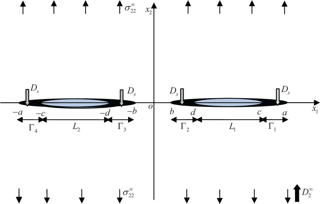
Schematic representation of the problem.
The boundary conditions of the problem may be mathematically expressed as
4. Solution of the problem
Boundary condition (i) and equation (9) lead to following Hilbert problem

Consequently its solution is written using equation (16) as

Using boundary condition (iv) and equation (9), one obtains

where
This introduces

where Λ = [HR]−1, HR = 2ReY, Y = Im(AB−1), i,j = 1, 2, 3.
One then writes equation (19) in component form as


Eliminating

The general solution of equation (23) using equation (15) may be written as

where
Analogously to determining Ω4(z), equation (22) is solved using boundary condition (ii) and equation (15), the solution may be written as

where

and θd, θc, R1 can be found in appendix A.
5. Applications
Closed-form expressions are derived for SIF, saturation zone lengths, COD, COP, and ERR.
5.1. Stress intensity factor
The SIF, KI (at the crack tip), is determined using the definition at the tip x1 = d

and at the tip x1 = c

Evaluating σ22(x1) using equations (9), (20), and (24) and boundary condition (iii) and substituting the result into equations (26) and (27) and simplifying, one obtains at the tip x1 = d

and at the tip x1 = c

5.2. Saturation zone size
The electric displacement ahead of the crack tip is determined using

Substituting the values of Ω2(x1) and Ω4(x1) from equations (24) and (25) and simplying we obtain

Extending the Dugdale hypothesis for electric displacement to remain finite at every point of a piezoelectric ceramic under the linear piezoelectricity theory assumption, one obtains two non-linear equations, one at the tip x1 = b

and one at the other tip x1 = a

These results enable one to determine a and b, and the saturation zone is than determined by (a − c) and (d − b), respectively.
5.3. Crack opening displacement
The COD, giving the relative opening of the faces of the crack, is defined as the jump displacement vector as

Using equations (8) and (24), one obtains


where
5.4. Crack opening potential drop
The COP is obtained equating the fourth component of equation (34) and equation (25) as at the tip x1 = d

and at the tip x1 = c

where R3, R4, and R5 can be found from appendix A.
5.5. Energy release rate
The local ERR is calculated [17] using the equation at the tip x1 = d

and at the tip x1 = c

The apparent ERR or global energy release rate, Ja, at the inner and outer crack tips is calculated using


6. Case study
A case study is presented to investigate the behaviour of various parameters, such as saturation zone size, SIF, COD, ERR, as the applied load is increased, resisting the crack growth. The material constants are given in Table 1, which are taken from Ou et al. [18]. We assumed that the lengths of the cracks are 10 mm and the saturation limit electric displacement, Ds = 0.03C/m2, which is taken from Loboda et al. [19].
The material properties constants.

Units: elastic constant, 109 N.m−2; piezoelectric constant, C.m−2; dielectric constant, 10−9 C (V.m)−1.
Variation of SIF, KI, versus the normalized inter-crack distance is plotted in Figure 2 for different piezoelectric ceramics and

SIF versus inter-crack distance for different piezoelectric ceramics.
Components of Irwin’s matrix HR and its inverse matrix Λ = [HR]−1 for different piezoelectric ceramics.
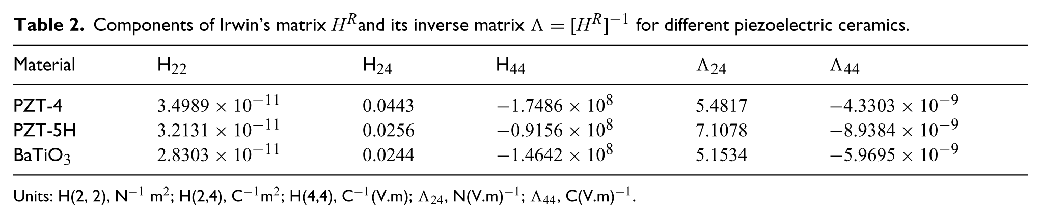
Units: H(2, 2), N−1 m2; H(2,4), C−1 m2; H(4,4), C−1 (V.m); Λ24, N(V.m)−1; Λ44, C(V.m)−1.
SIF, KI, is plotted against increasing prescribed electric displacement in Figure 3 for different piezoelectric ceramics. It is observed that as the load is increased the SIF also increases both at the inner and outer tips of the crack. It is to be noted that the SIF is considerable higher at the inner tip vis-a-vis that at the exterior tip of the crack for all the ceramics considered. Ceramic PZT-4 shows the highest stress concentration and ceramic PZT-5H shows the least concentration.

SIF versus electric displacement load for different piezoelectric ceramics.
Figure 4 depicts the saturation zone sizes for ceramic PZT-4 at the interior and exterior tips of the crack when the electric load ratio,

Normalized saturation zone length versus electric displacement load ratio for PZT-4 ceramic.
COD over the rims of the cracks is plotted in Figure 5. The dotted line shows the COD for a single centre crack problem for ceramic BaTiO3. It may be noted that the crack rims open symmetrically with respect to the middle point of the crack. The COD for two symmetrically situated cracks shows a shift in COD toward the internal crack tip. Also, the COD is larger in this case as compared to the single centre crack, as expected. It may also be noted from Figure 5 that ceramic PZT-4 has the maximum opening and that the crack opens less for ceramic BaTiO3.

COD profile over the crack surface.
Variation of COP versus normalized inner and outer saturation zones is drawn in Figure 6(a) and (b) for ceramic PZT-4. It is observed that the potential drop is more at the inner zone than that at outer zone, as expected. As the inter-crack distance, 2d/(c − d), is increases, the COP decreases at both the crack tips, but a drop in COP is higher at the inner tip when compared with that at the outer tip.

COP at the (a) inner and (b) outer saturation zones for PZT-4 ceramic.
Figure 7 depicts the variation of the local ERR at the inner and outer crack tips versus the normalized inter-crack distance for different piezoelectric ceramics. It can be seen from the Figure 7 that the local ERR is more at the inner crack tip than the outer crack tip. It is also observed that with an increase in inter-crack distance the local ERR at the inner and the outer tips becomes equal. This is because of the mutual influence of the cracks on each other decreases as the distance between them increased. Also, this is because the local ERR depends on factor VTHV. It is maximized for ceramic PZT-4 and minimized for ceramic BaTiO3; therefore, the local ERR is maximized for ceramic PZT-4 and minimized for ceramic BaTiO3.

Local ERR versus inter-crack distance for different piezoelectric ceramics.
Figure 8 depicts the variation in the global ERR versus the applied mechanical loading,

Global ERR versus applied mechanical loading for different inter-crack distance and PZT-4 ceramic.
Figure 9 shows the variation of the normalized global ERR versus the applied electric loading,

Normalized global ERR versus applied electric displacement load for different inter-crack distance and PZT-4 ceramic.
7. Conclusion
A strip-saturation model is proposed for a poled piezoelectric plane cut along two equal collinear hairline straight cracks under in-plane mechanical and electric loads. Closed-form expressions are derived for the SIF at the actual interior and exterior tips of the crack, ERR, COD, and COP drop. Two non-linear simultaneous equations are obtained to determine the saturation zone length.
The crack effect on the SIF and the ERR depends on the distance between them. The effect of cracks on each other weakens when the distance between the cracks increases.
Footnotes
Appendix A
Acknowledgements
The authors gratefully acknowledge the discussion and encouragement of Prof RD Bhargava (Senior Professor and Head (retired), Indian Institute of Technology Bombay, Mumbai) during the course of this work.
Declaration of conflicting interest
None declared.
Funding
The second author is grateful to Ministry of Human Resource Development (MHRD) for the financial support.