
Abstract
Cosserat (micropolar, asymmetric) elasticity can better predict the mechanical behavior of the materials with a characteristic length scale than the classical theory of elasticity. However, the area of fracture modelling in a Cosserat medium is not widely presented in the literature. The simulation of cracks in a Cosserat medium using the eXtended Finite Element Method (XFEM) is presented in this paper. The proper crack tip enrichment of the translational and microrotational fields is important for the robustness and efficiency of the XFEM/Cosserat model. Using the example of an edge crack of the Mode I in this paper, we have shown that the values of the J-integral for the Cosserat solid are higher than those for the equivalent classical elastic solid. The difference becomes significant for the cases of materials with strong micropolar properties. The dependence of the fracture behavior of the crack of different sizes on the Cosserat elastic constants was found to be significant. Therefore, it is recommended that the special tip enrichment is considered for the microrotational field, and a careful analysis of the material parameters is performed in order to model fracture in a Cosserat medium.
1. Introduction
The simulation of the fracture behavior of materials with intrinsic length scales (such as grains, particles, etc.) remains a challenge to the computational mechanics community. However, the scale of the microstructure contributes significantly to the overall behavior and the strength of materials such as polymers, graphite, composites, cellular solid, bones, etc. The Cosserat elasticity theory, being a higher order gradient theory, effectively represents the scale dependent behavior of materials with significant microstructure [1, 2]. The Cosserat theory of elasticity was first proposed by the Cosserat brothers [3]. Later, works by Shaefer [4, 5], Eringen [6] and Nowacki [7] gave further development of the Cosserat theory, and the new name for the theory was introduced: the theory of micropolar or asymmetric elasticity. The Cosserat elasticity theory considers a medium as a continuous collection of particles that behave like rigid bodies having three independent microrotations at each point, in addition to three classical translational degrees of freedom. The isotropic Cosserat continuum has six elastic constants, in contrast to just two constants of the classical elastic continuum. The couple stress tensor is introduced in addition to the conventional stress tensor. This leads to an additional set of equilibrium equations that account for the moments. The essential feature of a micropolar continua is that the stress tensor is not necessarily symmetric, so that the balance of momentum equation should be modified accordingly. The presence of the rotational degrees of freedom allows us to explicitly model the mechanical behavior of a heterogeneous material with microstructure, while considering it as a continuum (see, for example, [8–19] ). For example, the Cosserat theory is able to model discrete media, where interblock or interlayer slip occurs under loading, such as discontinuous rock masses and layered materials [20, 21]. In both cases, this type of deformation is independent of the macroscopic deformation of the system. Considering the bone structure, the mechanical properties of the bone are better described by the Cosserat theory than the classical theory of elasticity [22, 23]. The size effect in torsion tests of bone specimens was predicted by the Cosserat theory, according to Lakes [24] and Yang and Lakes [25].
The present paper focuses on a way to combine the eXtended Finite Element Method (XFEM), which is widely used in the area of the fracture mechanics, with the Cosserat elastic model. The XFEM was first introduced for the linear elastic fracture mechanics problems by Belytschko and Black [26] and Moes et al. [27]. Then, it was effectively applied for the modelling of different kinds of discontinuities in elastic solids such as various types of cracks [28–30], interfaces [31], inclusions [32], dislocations [33–35], and so on.
The XFEM is a numerical method that allows one to model the geometry of the discontinuity independently of the mesh. The geometry of the crack is convenient to define using the level set method [36]. The main idea of the XFEM is to introduce special enrichment functions to the displacement approximation, depending on the type of discontinuity [27]. For the crack problem, the elements containing the crack tip and some elements in the vicinity of the crack tip are enriched with the branch functions that span the asymptotic field. The Heaviside step function is used for the elements cut by the crack, but not enriched with the branch functions. This technique allows the modelling of the crack propagation without the need to re-mesh, which is an advantage over the Finite Element Method (FEM), where the crack surface must conform to the mesh. In the XFEM/Cosserat model presented here, both the translation and microrotation fields in the vicinity of the crack tip are enriched by the functions spanning the asymptotic fields [37] and by the Heaviside function away from the crack tip.
In the area of the Linear Elastic Fracture Mechanics (LEFM) for the Cosserat materials, very few numerical models have been presented, in contrast to experimental and analytical work. Amongst the first investigations in the field, the finite element analysis was performed to study the stress concentrations around a blunt crack in the Cosserat solid by Nakamura and Lakes [38]. The stress concentration factors were shown to be smaller than those of the classical problem. Simultaneously, the experimental studies of the cracks in the bones, considered as the Cosserat solids, were performed [22, 39]. Although, it falls out of the LEFM scope, it is worth mentioning that the wide implementation of the FEM/Cosserat model lies in the field of geomechanics, such as modelling of shear band formations and strain localizations. In Khoei and Karimi [40], a combined XFEM/Cosserat continuum model to simulate the strain localization in elasto-plastic solids was proposed. In Khoei et al. [41], the non-linear behavior of Cosserat materials, particularly plastic deformation, was modelled by representing material interfaces independent of the finite element mesh. Due to complexity of fracture modelling in Cosserat materials and the lack of information on the fracture parameters, the numerical simulations of the cracks in the Cosserat elastic medium are poorly covered up to date. In the present article, the XFEM model of the Mode I and II edge cracks in the Cosserat elastic solid are presented and discussed. The calculation of the energy release rate is performed. The obtained results could give a new rise to the modelling of the crack propagation problems in the Cosserat elastic solids.
This article is organized as follows. In Section 2, the concepts of the linear elastic fracture mechanic applicable to the crack modelling in the Cosserat materials are presented. In Section 3, the problem formulation and the governing equations are given. In Section 4, the extended finite element method formulation and the discrete equations are stated, and the numerical integration scheme is described. In Section 5, several numerical examples are presented. First two examples introduce the verification of the XFEM model and the convergence study for the Mode I and II edge cracks in the Cosserat medium, respectively. In the third example, the calculation of the energy release rate for the Mode I edge crack is presented and verified, and the comparison of the J-integral for the Cosserat and classical elasticity problems is performed for varying coupling levels. The conclusions are given in Section 6.
2. Modelling of fracture in Cosserat media
Crack tip behavior in classical linear elastic fracture mechanics is described by three crack opening modes, modes I–III [42]. Due to the presence of the additional degrees of freedom (microrotation) in Cosserat theory, crack tip behavior is described by three crack opening models plus three higher modes, bending modes IV–VI [43, 44]. These bending crack modes describe discontinuities in the microrotations and the moment stress concentrations at the crack tip. Fracture theory for Cosserat continua is still in its infancy. The J-integral (energy release rate) for a crack in a Cosserat media has six components, compared to three for classical elasticity [45]. While in classical linear elastic fracture mechanics there is a well-established relationship between the energy release rate and the stress intensity factors,
Diegele et al. [37] derived the form of the two-dimensional asymptotic fields for the displacements near a crack tip in a Cosserat medium:
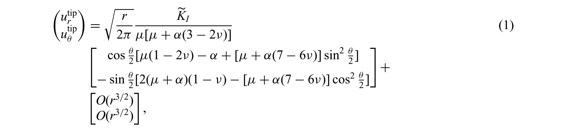

where
The degree of coupling of the displacements and rotations is governed by elastic constant
It is noteworthy that
2.1. Functions spanning the asymptotic solution
Careful manipulation of the asymptotic displacement solutions for an elastic crack in a Cosserat continuum (1) shows that the crack tip displacements are asymptotically spanned by the same four (branch) functions which span the Williams solutions of classical linear elastic fracture mechanics, i.e.

where
From direction observation of the asymptotic microrotation fields for an elastic crack in a Cosserat continuum (2), it is clear that the first order term is spanned by:

The above sets of functions will be the basis for XFEM enrichment of the crack tip translation and microrotation fields.
2.2. The J-integral for a Cosserat continuum
The Cosserat equivalent to the J-integral has been derived in numerous ways [43–45, 47]. Following the derivation presented by Lubarda and Markenscoff [45], the energy release rate (in the absence of the body forces and body moments) for plane strain micropolar elasticity is:

where i and j are the Einstein indices;

where

where
3. Problem formulation
Consider a linearly elastic domain

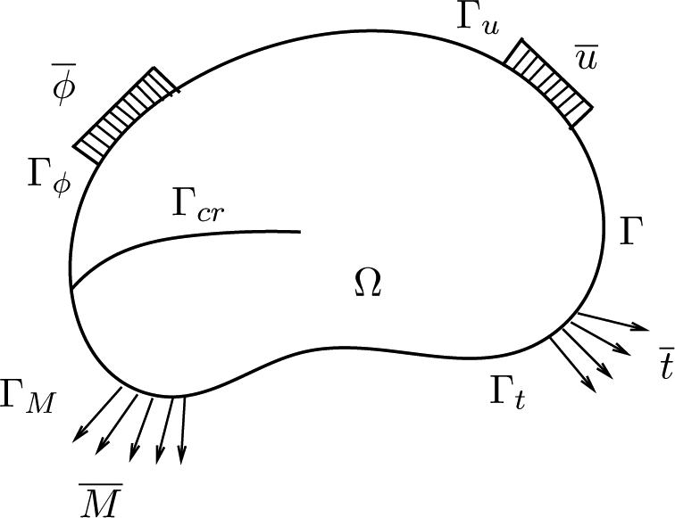
Body with external and internal boundaries subjected to loads.
In two dimensions, the governing equilibrium equations are


where


where
The translations


where

The linear constitutive equations for the coupled model are:


where

and

where
3.1. Weak form
Following the standard Galerkin procedure, the following weak form of the coupled boundary value problem governing an elastic Cosserat medium can be derived.
Find


where


and


where
4. The eXtended Finite Element Method
Consider a crack
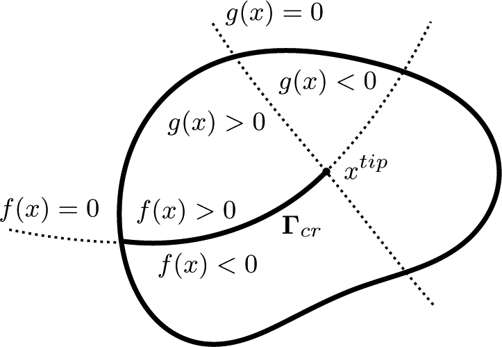
Level set method for the crack positioning.
Following the XFEM methodology developed by Belytschko and Black [26] and Moes et al. [27], the FEM displacement approximation is enriched by the Heaviside step function at nodes with supports cut by the crack (denoted by circles in Figure 3) and by a set of tip functions which span the asymptotic crack tip fields for nodes within a given domain about the crack tip (denoted by squares in Figure 3).
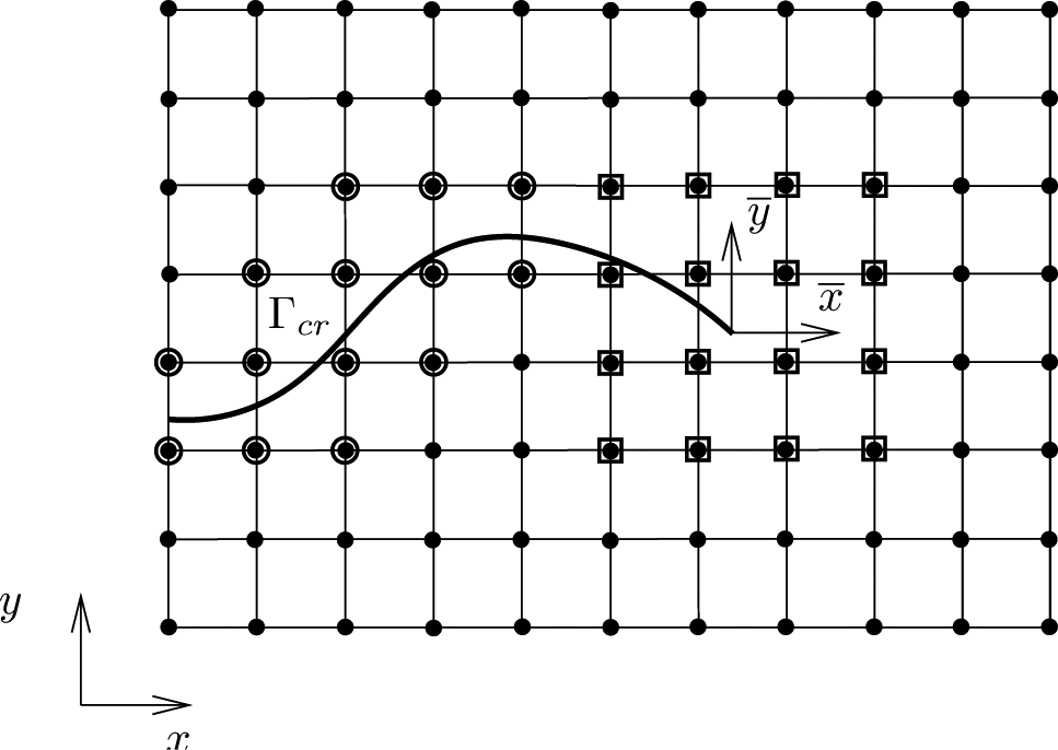
Illustration of a two dimensional domain containing a crack
The XFEM approximation for the translation and microrotation for a crack in a linearly elastic Cosserat continuum are
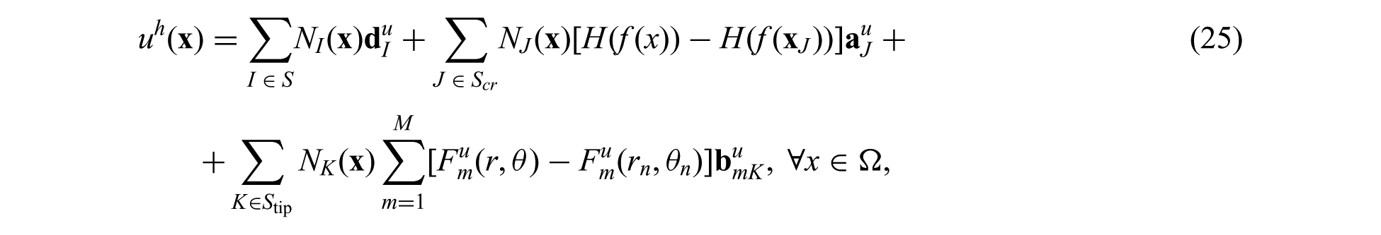
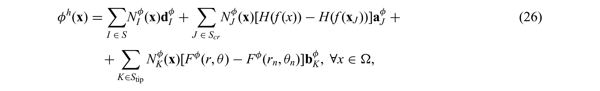
where
The nodes in

where
The Heaviside step function is defined in the usual sense as

The enrichment functions
4.1. Numerical integration
In order to achieve high quality results and optimal convergence rates, accurate numerical integration of the discrete equations is required since the gradient of the tip enrichment functions are singular at the crack tip and the Heaviside enrichment function is discontinuous across the crack surface [49–52]. Integration over the unenriced elements, Heaviside enriched elements and the crack tip element is done by second-order Gauss quadrature rules, element subdivision combined with the second-order Gauss quadrature [27], and element subdivision combined with 15th-order almost polar integration Gauss quadrature [50]. Lastly, for the elements that are enriched by the branch functions but do not contain the crack tip, an 8th-order Gauss quadrature rule is used.
According to Khoei et al. [41], several aspects are crucial in order to obtain accurate results and optimal convergence rates in the XFEM modelling:
The proper integration rules in the elements cut by a crack and containing a crack tip should be considered.
The geometrical enrichment is crucial to obtain optimal convergence rates. It allows us to get the optimal convergence rate in oppose to the topological enrichment, when only particular number of nodes layers are enriched.
Blending elements allow for the smooth transition between enriched and un-enriched subdomains by using the special weight function with compact support.
4.2. Blending
Another important issue for the accuracy of the solution in the XFEM is the blending elements [52, 54, 55]. The blending elements are those that have some of the nodes enriched and some of them un-enriched. The standard enrichment can add parasitic terms to the approximation space of the blending elements, i.e. the reproducing property of the partition of unity is lost. No difficulty occurs in the blending of the shifted Heaviside enrichment, because the enrichment is only considered for the elements cut by the crack. Errors due to blending of the branch function for this problem are negligible and do not affect the convergence rate of the XFEM. Therefore, no blending treatment has been adopted in this work.
4.3. Crack tip enrichment domain
To obtain optimal convergence rates with the XFEM, the tip enrichment domain around the crack tip must be a constant (i.e. independent of the element size); this enrichment scheme is called the geometrical enrichment [49, 50]. This enrichment scheme is used in all convergence studies presented in this article.
5. Examples
In this section, three numerical examples are presented to demonstrate the XFEM simulation of the cracks in the Cosserat elastic solid. The first and second examples introduce the solutions of the Mode I and II edge crack problems, respectively. The patch tests and the convergence properties of the method are demonstrated for both cases. The third example presents the numerical calculation of the energy release rate for the edge crack problem under tension. The J-integral is calculated for the several crack sizes, considering varying Cosserat elastic parameters, and compared to the J-integral of the classical elasticity.
5.1. Mode I edge crack
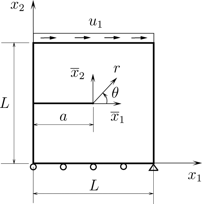
A square plate of size
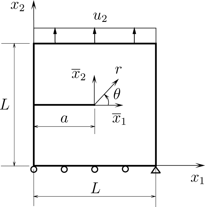
The domain with an edge crack under tension.
In order to perform the convergence study for the Mode I and II edge crack problems, the normalized energy norm is employed as a convergence criterion. The employed mesh sizes are 11
The energy norm is defined as

where
The energy norm is normalized as:

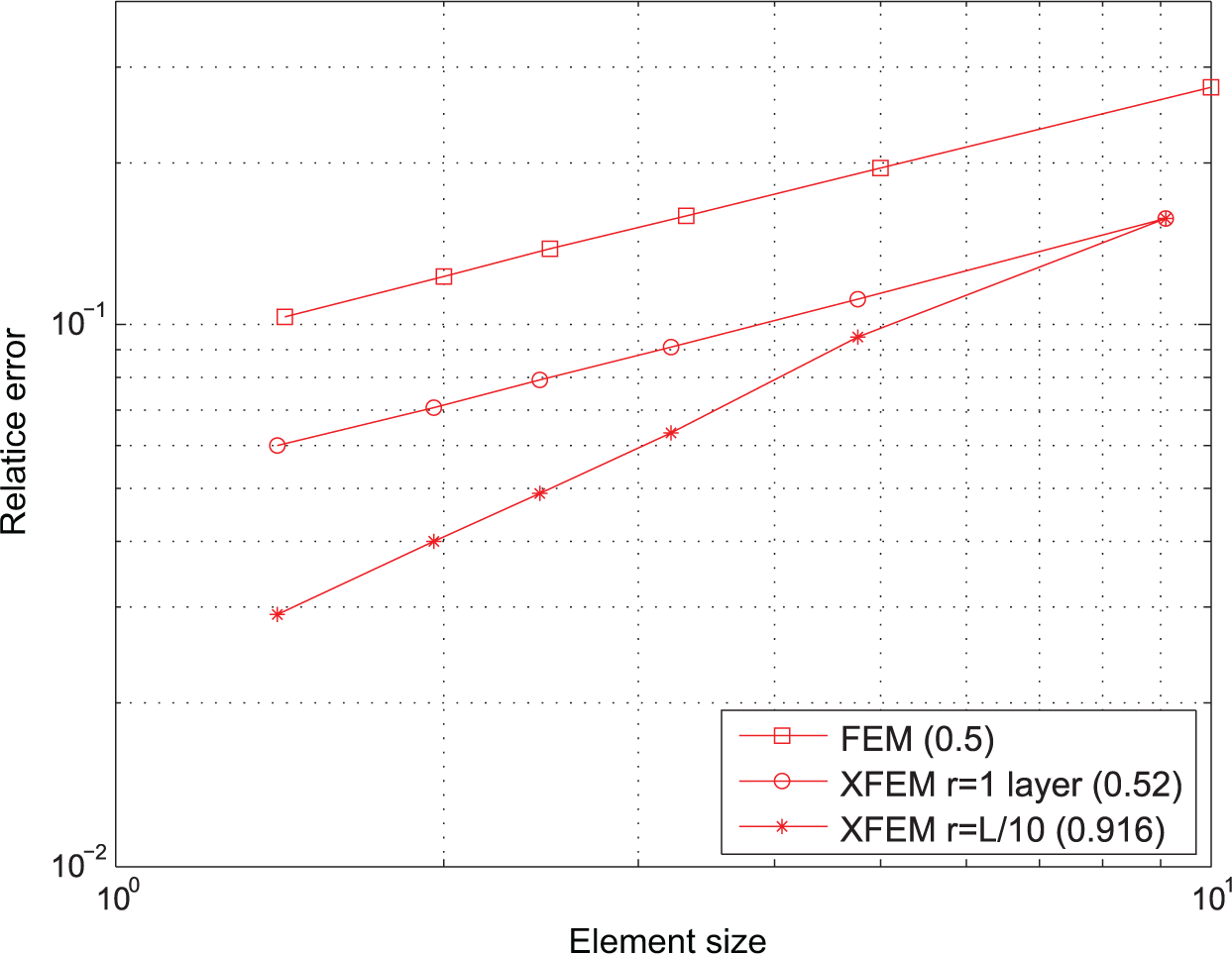
The solution of the addressed Mode I edge crack problem by the FEM with the mesh of 40,000 elements was taken to be the exact solution. Two types of the tip enrichment zones were considered for the convergence study of the XFEM solution: the topological tip enrichment of one layer of nodes around the crack tip and the geometrical tip enrichment of the size
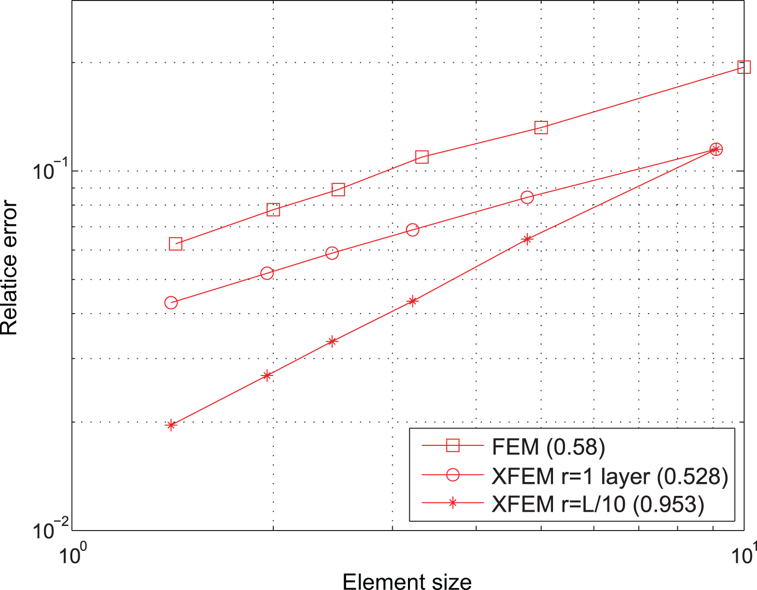
Convergence study for the Mode I edge crack problem.
As expected, the optimal convergence rate of approximately 1 in the energy norm for the XFEM with geometrical enrichment is obtained. The suboptimal convergence rates of 0.5 in energy norm are obtained for the XFEM solutions with topological tip enrichment and for the FEM solution. The geometrical tip enrichment of the size
5.2. Mode II edge crack
In the second example, a Mode II edge crack problem is studied. Consider a square plate of size
The domain with an edge crack under shear.
The error estimation procedure, described in the first example, is performed for the convergence study for the Mode II edge crack problem (Figure 7). Again, the optimal convergence rate of 1 in energy norm was obtained for the XFEM solution with the geometrical tip enrichment, and the suboptimal convergence rate of approximately 0.5 in energy norm was obtained for the XFEM solution with the topological tip enrichment and the FEM solution. The slight decrease in the convergence rates from the optimal values is observed, but expected. In order to get higher convergence rates, the very fine mesh should be considered for the exact FEM solution. Although, the computational time will increase drastically.
Convergence study for the Mode II edge crack problem.
Concluding, the results of the convergence studies for the cracks of Modes I and II in the Cosserat medium allows us to rely on the developed XFEM model with confidence.
5.3. J-integral computation
5.3.1. Verification
The calculation of the J-integral for the Cosserat elastic solid is performed using the contour integral (5). The most important concept of the contour integral—path-independence under the static condition—is satisfied in our calculations. Considering the contour as a circle, the obtained values of the J-integral are constant for the radii greater than
In order to verify the calculation of the J-integral, two specific tests were proposed. In the first test, the Cosserat problem was fully reduced to the classical case and the calculated J-integral was compared to the one of the corresponding analytical solution of the classical J-integral. Assuming the plane strain condition, the classical J-integral is calculated as

For the test, the Mode I edge crack in the domain with the prescribed analytical solution on the boundaries [49] was considered. The numerical values of the calculated J-integral was found to be less than 1% different from the analytical values.
For the second test, Mode I and II edge crack were considered in the Cosserat elastic medium with
The obtained results verify the most important characteristics of the contour J-integral, which allow us to proceed to the study of the energy release rate for the Cosserat medium.
5.4. Comparison of the J-integral for the Cosserat and classical elastic solids
Consider the domain illustrated in Figure 8. A plate of height
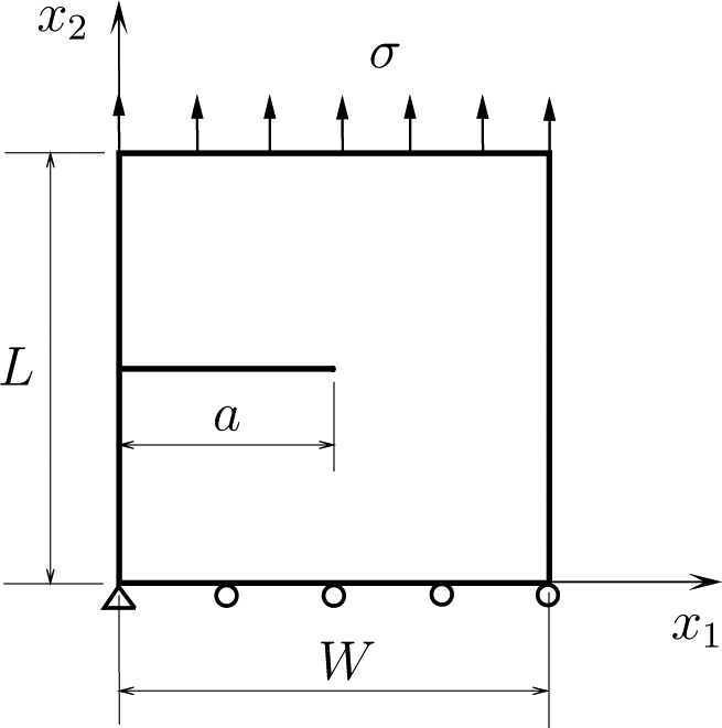
The domain with an edge crack under tension loading.
In this example, the effect of the crack size on the J-integral is analyzed. Several cases are considered depending on the values of the Cosserat elastic constant, which influences the level of assymetricity of the stress and strain tensors. For this study, parameter
The numerically calculated J-integral for the Cosserat elasticity is compared to the one of the classical elasticity. The exact stress intensity factor solution of the addressed problem for the classical elasticity is given by Pasternak et al. [44]:

where
For

The reference J-integral of the classical elasticity for the Mode I crack under the plane strain condition is related to the stress intensity factors as follows:

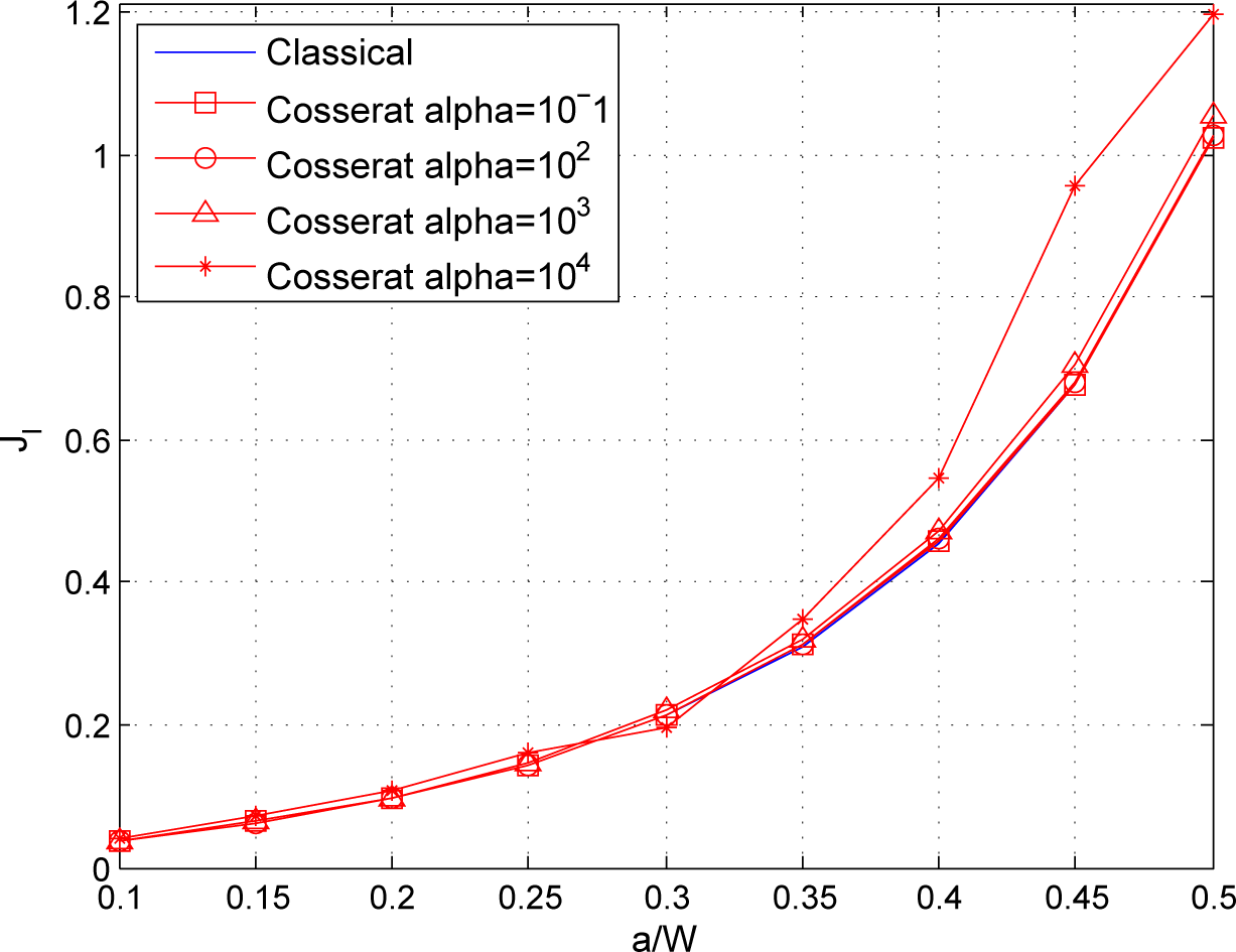
Figure 9 summarizes the J-integral calculations versus the crack size for the Cosserat problem, parametrized by

where
The J-integral versus the crack length.
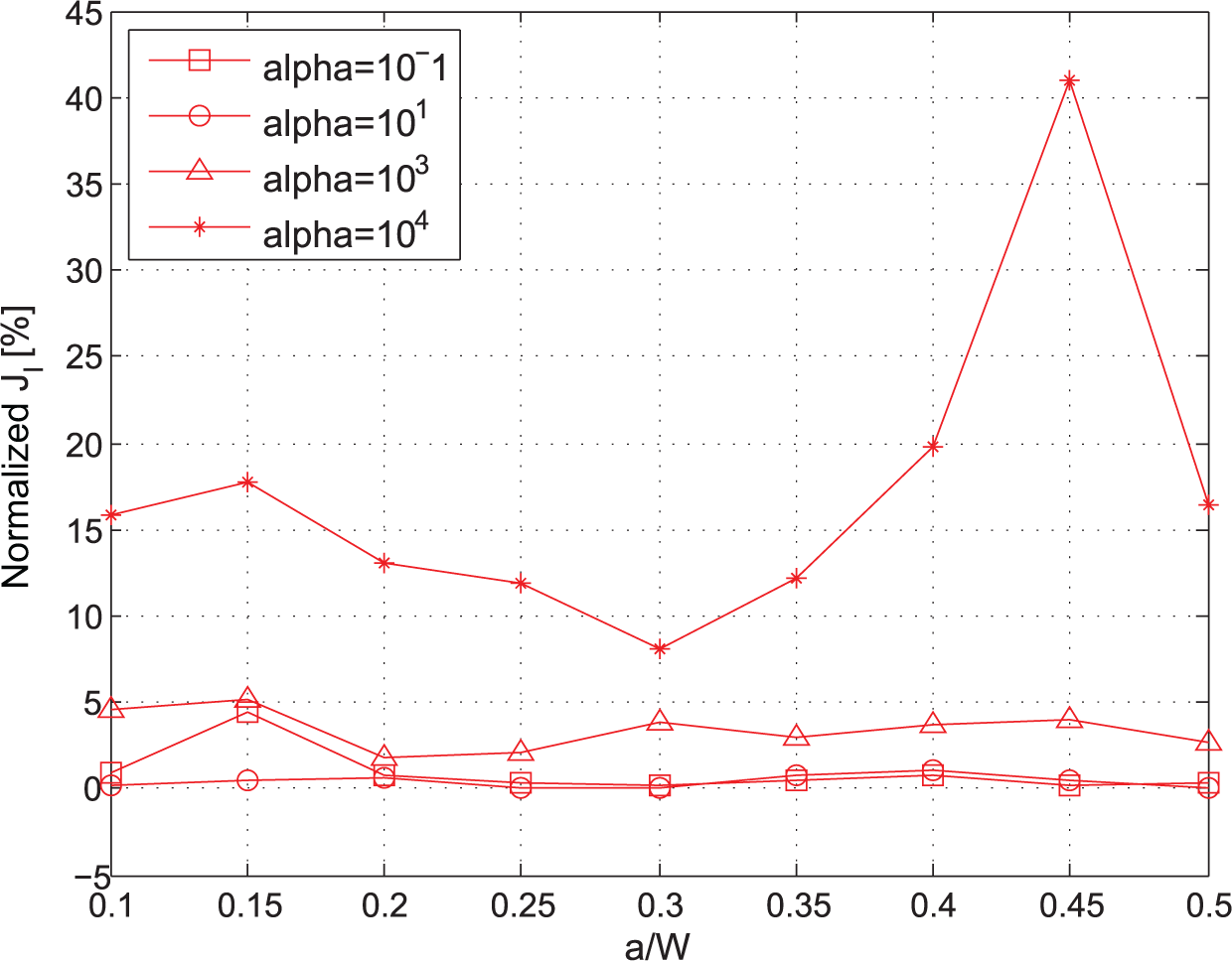
The normalized J-integral with respect to the crack length.
It can be seen that the behavior of the J-integral for the Cosserat elasticity is similar to that of the classical elasticity for the
The difference of up to 40 % between the values of the J-integrals when the material constant

which is called the polar ratio.
Based on the results of these studies, the J-integral presented by Atkinson and Leppington [47] is valid for the calculations of the energy release rate in the Cosserat medium. In general, the higher values of J-integral are obtained for the problems with the microrotations involved than the J-integral of the classical elasticity. This means that, under the same boundary conditions and loading mode, a crack grows faster in the Cosserat elastic solid than in the classical elastic solid. For the higher values of the Cosserat parameter, the crack will grow up to 40% faster in the Cosserat material.
6. Conclusions
The simulation of the edge cracks of Modes I and II in a Cosserat medium using the XFEM was presented. The numerical calculation of the path-independent J-integral for the Cosserat elastic medium was introduced. The Cosserat J-integral dependence on the crack size was studied for the parameter
Based on the results obtained from the convergence studies, it is recommended that the proper branch functions for the translational and rotational degrees of freedom and geometrical tip enrichment zone are considered for the modelling of cracks in Cosserat solids in order to obtain the optimal convergence rates for both Mode I and II cracks. For the J-integral calculation the elastic constants should be carefully measured and evaluated while modelling the cracks in a Cosserat elastic media, as they affect the fracture behavior of the material.
Footnotes
Funding
The author(s) received no financial support for the research, authorship, and/or publication of this article.