
Abstract
The main subject of this paper is the micro-mechanical analysis of a piezoelectric ceramic. In micro-mechanical analyses, it is very important to have knowledge about the real and natural micro-structure of materials. Therefore, the barium titanate powder was prepared using the solid-state technique, and pellets and beams were manufactured by uniaxial and isostatic pressing. The boundary element method (BEM) is used in order to be combined with three different grain boundary formulations for investigation of micro-mechanics and crack nucleation and evaluation in piezoelectric ceramic. In order to develop a numerical programming algorithm, suitable models of polycrystalline aggregate have to be discretised for the BEM analysis. Hence, original comprehensive algorithms are designed on the basis of image processing methods. Several assumptions are made to model the grain boundary in micro-scale. In the first step, before having any cracks, the traction equilibrium and displacement compatibility are governing equations. When the onset micro-crack starts to initiate, one mixed-mode potential based cohesive law is applied to model grain boundaries and investigate the intergranular crack nucleation and evolution. Upon interface failure, a frictional law is utilised in order to study separation, sliding or sticking between micro-crack surfaces. Several numerical experiments on barium titanate polycrystalline aggregate are presented to show the effectiveness of image processing-based discretisation algorithms and grain boundary formulation in micro-mechanical analysis.
Keywords
1. Introduction
Nowadays, very complex numerical simulations for nano-scale to macro-scale materials take a lot time and need powerful computational machines. For this reason, proposing new methods to improve computational procedures can lead to more efficient numerical tools.
The boundary element method (BEM) is one of the most diffused computational methods in many areas of engineering and science, including fracture mechanics, fluid mechanics, electromagnetism, acoustics and geology [1–5]. In fact, this method allows in a very simple way to both save time and perform calculations: in order to use the BEM, one needs to discretise only the boundary of the system, so the computational efficiency can be increased significantly [6,7].
In order to utilise the BEM, it is essential to use the traction fundamental solution and the displacement fundamental solution, which can be obtained for anisotropic bodies by using two main methods. The first method is based on Stroh’s formulation [8], and it is utilised in the current study, and the second one refers to Lekhnitskii’s formalism [9].
The micro-mechanical analysis, via computational procedures, allows one to understand how much grain size and orientations can influence the crack initiation or fracture criteria in composites. Secondarily, it is useful to determine the effective mechanical properties of materials. To this aim, different methods have been proposed [9–13]. The investigation of effective properties of materials is mostly used for composites that contain cracks, holes or rigid bodies. Some composites also consist of a matrix phase. So, it is necessary to consider a unit cell with periodically distributed inclusion and then analyse it by using the BEM [10] or finite element method (FEM) [14] for evaluating the overall material properties of the composite. This method has been used in the case of piezoelectric ceramics [11]. However, they did not consider the cohesive law and pre-existing cracks in their modelling, which play important roles in determining the effective behaviour of materials.
In order to predict the fracture behaviour in a composite, different cohesive law models or friction phenomena can be used [15–25]: via cohesive law models, it is possible to predict both intergranular and transgranular crack initiations. In other words, a cohesive law is suitable in order to model interfaces between materials with different mechanical properties. Depending on the possibilities to predict fracture and crack initiation, there are two different kinds of cohesive law models, the potential-based law [16–18] and the linear law [19–22].
Crack nucleation and propagation in polycrystalline materials can be studied in cohesive models by different numerical tools such as the BEM or FEM [26,27]. Despite the fact that some of the cohesive laws consider fracture criteria for the first and second mode separately, in [28,29] mixed-mode relations to predict the location of the cohesive zone in polycrystalline are presented.
The BEM has been used also in micromechanics and multistate modelling [30–32]. In some of these works, materials are modelled only in micro-scale and neither cohesive law nor averaging theory or nonlocal theories were used. However, some basic concepts of micro-mechanical analysis, such as representative volume element or grain boundaries, have been used in the earliest works in the area of polycrystalline analysis, where a periodic arrangement of hexagonal grains was used to model the polycrystalline material at the micro-mechanical level. Symmetry considerations allowed Fotiu et al. [31] to restrict the models to representative unit cells with special boundary conditions. Sfantos and Aliabadi [33], Benedetti and Aliabadi [34] and Gulizzi et al. [35] have done a comprehensive research in using the BEM in the micro-mechanical analysis. Their works contain modelling of grain boundaries as well as generating a numerical algorithm.
For studying crack initiation and evaluation in a microstructure, suitable models have to be generated and prepared. The Poisson–Voronoi tessellation method is extensively used in order to generate a suitable model of polycrystalline materials [36,37]. However, it is clear that this method provides artificial microstructures and, for studying the scanning electron microscopy (SEM) images of specimens that are prepared in the laboratory, it does not have suitable solutions.
In order to have a bridge between the micro and macro analysis, averaging theorems have been suggested. It is worth mentioning that averaging theorems can be considered as a bridge in order to transfer all of the quantities from micro-scale to macro-scale [38–40]. In the current work the averaging theorems proposed in [41] are used. For a more rigorous approach, the reader can refer to, for example, [42–45].
This paper deals with the micro-mechanical analysis of failure in piezoelectric ceramic. In order to have knowledge about the micro-structures of ceramics, barium titanate pellets and beams have been sintered in different temperatures. Afterward, the SEM images of pellets that were sintered at different temperatures were prepared to achieve a reliable model of micro-structures. However, in order to perform the numerical analysis, these SEM images have to be analysed and discretised precisely for having geometrical information about grains boundaries. It is worth stressing that an algorithm, based on image processing methods, is designed for the first time, and we establish if it is able to discretise both the natural and artificial microstructure of materials. The numerical algorithm for utilising the BEM for every grain is developed, taking into account mechanical, electrical and piezoelectric properties. Then, three different statuses are considered to have accurate information about crack nucleation and evaluation in the grain boundary in micro-aggregate. Hereafter, suitable algorithms are created to combine the BEM with the cohesive-frictional grain boundary micro-mechanical model. An adaptive matrix is based on a numerical programming code able to combine the mentioned assumptions and change its elements according to the status of grain boundaries via considering mechanical, electrical and piezoelectric properties.
For some interesting applications of damage theories that can be considered we refer to, for example, [46] for a new meso-scale model related to a multi-phase composite material, [47] for a formulation based on variational tools and [48,49] for a particle system formulation. These articles can be used to start different approaches to the introduced problem.
2. Experimental procedure
2.1 BaTiO3 powder
The traditional solid-state method used in our research for BaTiO3 synthesis has strict criteria with regard to particle size and purity of the raw material, while it is also easy to produce non-homogeneous powders [50]. The advantages of the solid-state reaction used in mass production are its simplicity, precise stoichiometric control and low cost, with the main disadvantage being that the high calcining temperature results in very large and non-uniform grain sizes [51]. As a consequence, this method does not allow the production of materials with a high dielectric constant [51]. In order to eliminate the disadvantages of the solid-state reaction, a variety of novel wet chemical synthesis methods have been developed [52].
Three steps of calcination were applied in order to obtain BaTiO3 powder. The full report of these procedures was comprehensively explained in [53]. Figure 1 presents the X-ray diffraction (XRD) pattern of BaTiO3 after the third activation and calcination. We remark in Figure 1 that the third mechanical activation and calcination provide single-phase powder considering that the diffraction pattern of BaTiO3 powder after the third calcination and activation has revealed the tetragonal phase and fully overlaps with the standard.
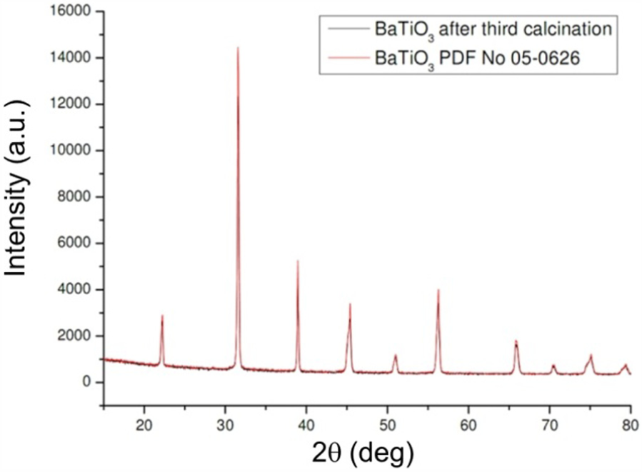
X-ray diffraction pattern of BaTiO3 powder after the third activation and calcination.
2.2 BaTiO3 pellets
Based on the lattice constant value (see [54]) in BaTiO3 pellets, the theoretical density is considered to be 6.02 g/cm3. Table 1 presents some properties of BaTiO3 pellets in which the relative density is very high and can be compared with [54].
The apparent density, water absorbability and apparent porosity of sintered pellets.

2.3 Grain size
One of the important parameters that can influence the mechanical and electrical properties of piezoelectric materials is the grain size of a polycrystalline aggregate. Not only is the intergranular fracture is influenced by grain size, but also the electrical response can experience a huge effect via changing the porosity and grain size of the microstructure. One of the popular methods to determine this feature is analysing images that are prepared by the SEM machine. Figure 2 presents the pellet surface at two different magnifications, ×350 (Figure 2(a)) and ×1000 (Figure 2(b)), in which compact densification can be observed. In the microstructure of polycrystalline BaTiO3 both large grains, which have sizes from 50 to 100 µm, and small ones, which have dimensions from 1 to 3 µm, can be seen. As shown in Figure 2, grains boundaries are very well fitted together and only slender pores are visible. These results are in agreement with the data for pellet densification presented in Table 1 and the investigations carried out by Yoon and Lee [55].
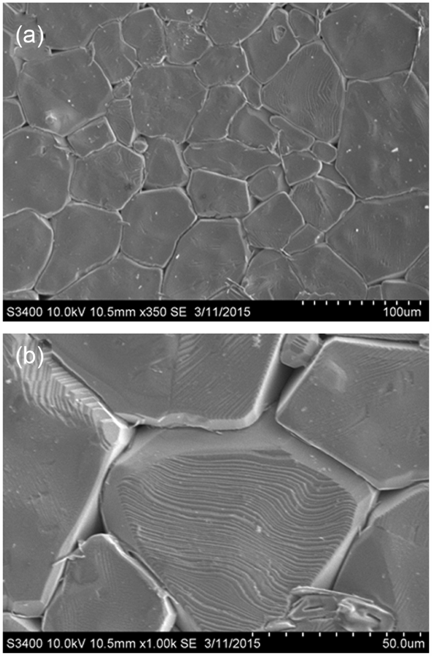
Scanning electron microscopy microstructure of the pellet surface at two different magnifications: (a) ×500; (b) ×1000.
3. Preparing the boundary element method model in computer-aided design software and the numerical programming algorithm
In order to analyse the microstructure of piezoelectric ceramics, it is essential to have some information on such as points on boundaries. Some researchers used the artificial microstructure created by a quasi-random point generator; however, this method is not able to discretise all kinds of artificial grains and the SEM image form laboratory. In this study, SEM images of specimens as well as artificial grains have been discretised by generating a comprehensive numerical algorithm.
Firstly, one image processing tools has been applied to allocated special pixels in every grain in the micro-structure. In the case of SEM images, the computer-aided design (CAD) software has been used in order to clarify the boundary of the SEM images. Afterwards, as shown in Figure 3, the output from the CAD software has been used in the MATLAB software and image processing tools in order to allocate special pixels for every grain in the polycrystalline aggregate. However, for the artificial specimen, we ignored the use of CAD software and the image was directly inputted to the image processing algorithm, as illustrated in Figure 4.
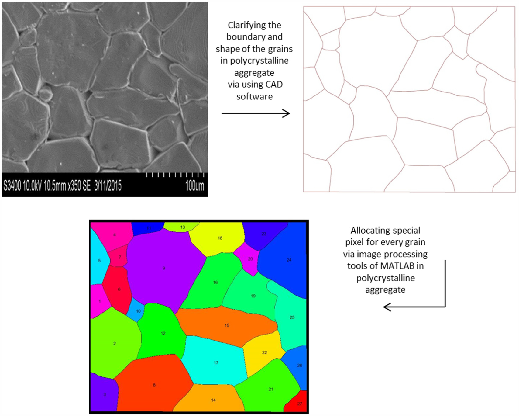
The procedure of allocating special pixels for every grain in the polycrystalline aggregate obtained by the scanning electron microscopy machine. CAD: computer-aided design.
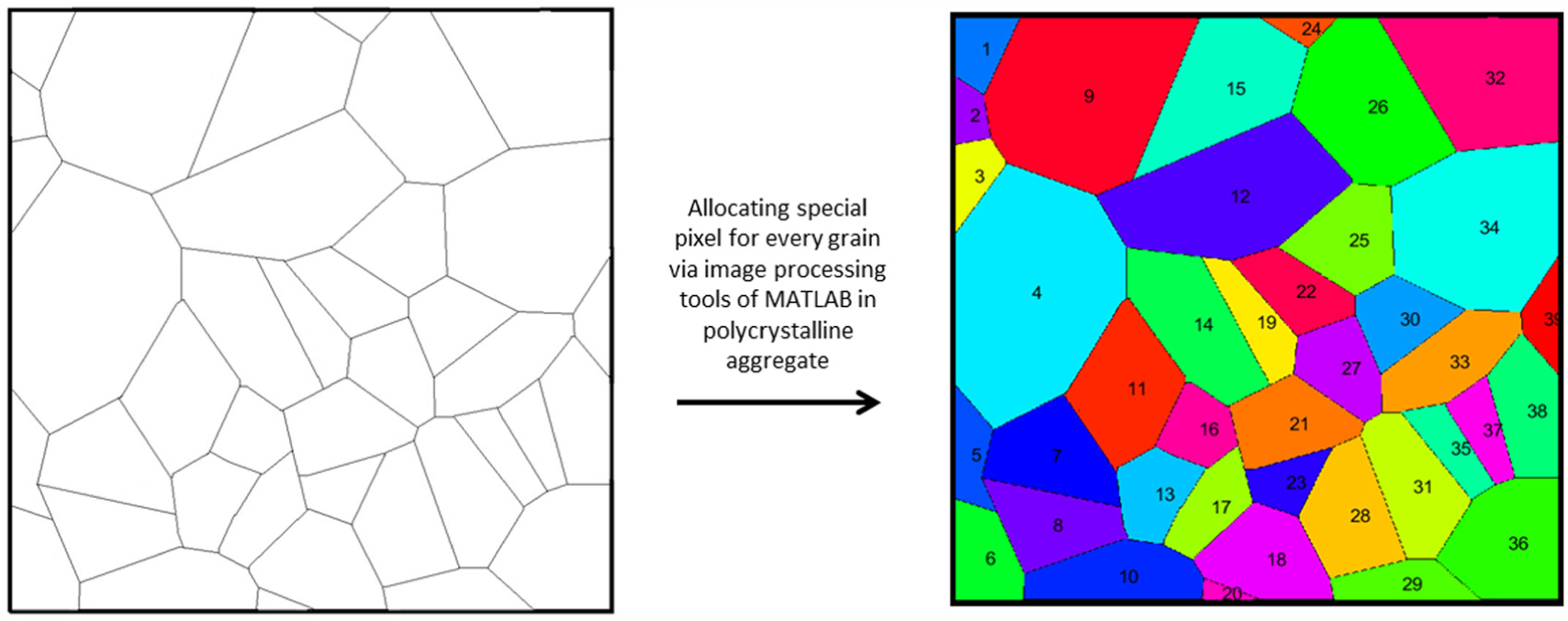
The procedure of allocating special pixels for every grain in the artificial polycrystalline aggregate.
In order to apply BEMs, the discretisation of the grain boundary is essential. So, some numerical algorithms were created to obtain the coordinates of the grain boundary via pixel information. Figure 5 presents the results of this process. It can be concluded that the generated algorithms were successful for both artificial grains and the SEM image and they are able to discretise the grains very well.
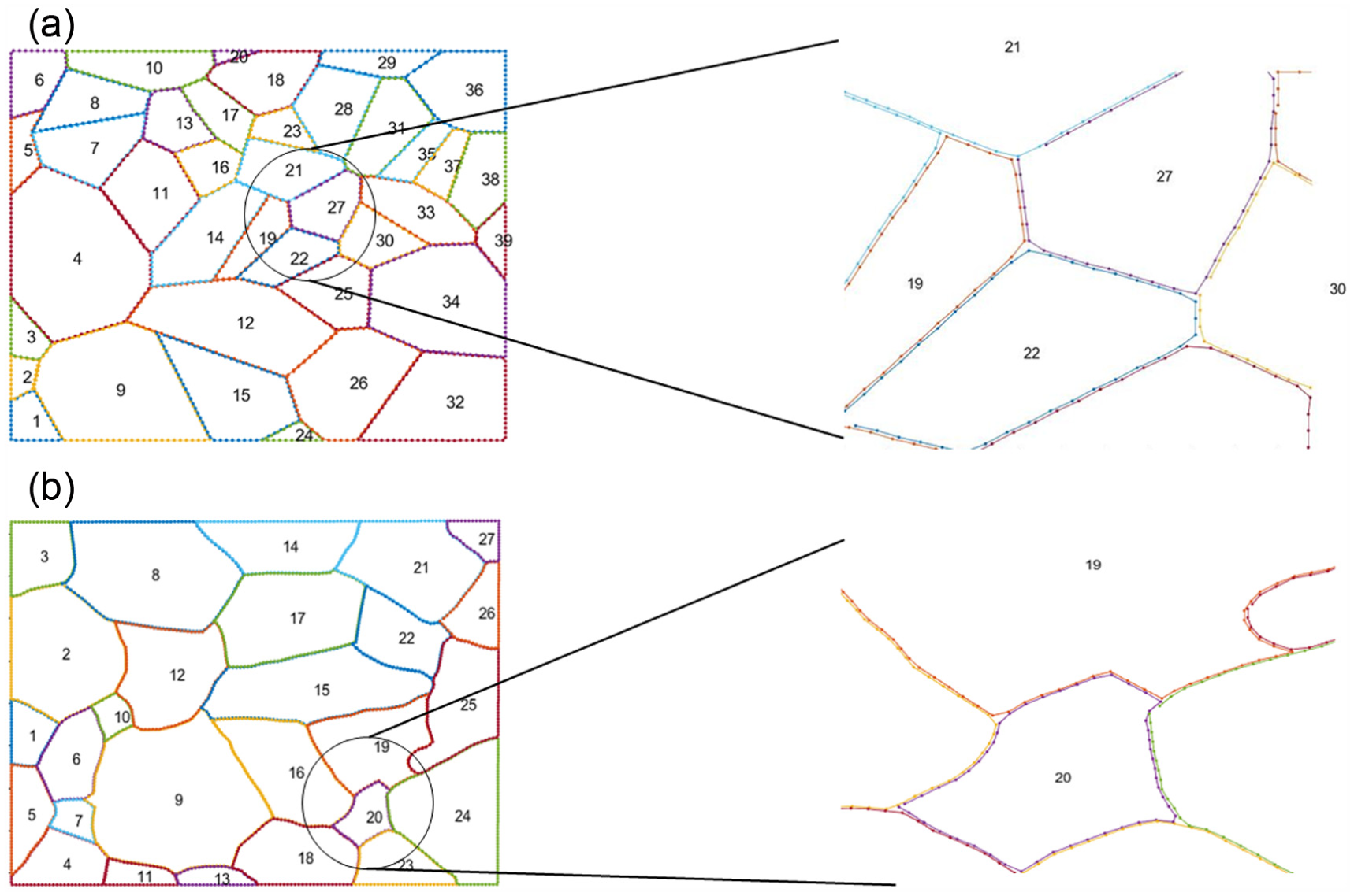
Node points on grain boundaries that are separated into grains in specimens of the grain boundary in two different views: (a) artificial microstructure; (b) microstructure obtained by the scanning electron microscopy image.
In this study, due to the low ratio of grain boundaries compared with grain surfaces, the grain boundaries will not be considered as a separate part, that is, the study of behaviour of grain boundaries will be ignored. In Figure 5, it is clear that there are gaps between grain boundaries and each grain has its own boundaries. So, the distances between grain boundaries must be eliminated and the grains must have the same boundaries in the area that they have contact. To achieve this goal, more numerical algorithms were designed in order to unify the boundary of grains that are in contact. The output of these algorithms is shown in Figure 6. As it is obvious in Figure 6, these numerical algorithms act very well: not only were the distances between the grains eliminated and they have unified boundaries, but also in the corners, the grains have the same coordinates, which will increase the accuracy of numerical models.
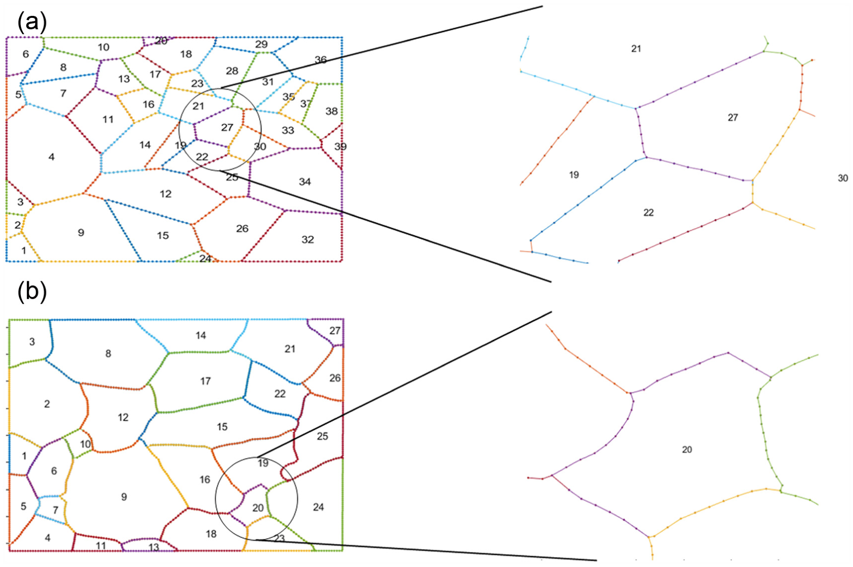
Discretised grain boundaries in two different views: (a) artificial microstructure; (b) microstructure obtained by the scanning electron microscopy image.
4. Application of the boundary element method in micro-scale
We consider the model of brittle materials for representation of the microstructure and the basic assumption that the whole microstructure consists of polycrystalline brittle materials. Due to a small area of grain boundaries compared with the grain, the modelling of them is ignored in the current research and only the intergranular fracture is the subject of the current study. To investigate crack nucleation, propagation and branching in brittle polycrystalline, the BEM (as suggested in [34]) is being used here. Let us write the constitutive relation for piezoelectric ceramics in two dimensions, namely the 1–3 plane. As is known, there is an extra field in piezoelectric materials, namely electric displacement
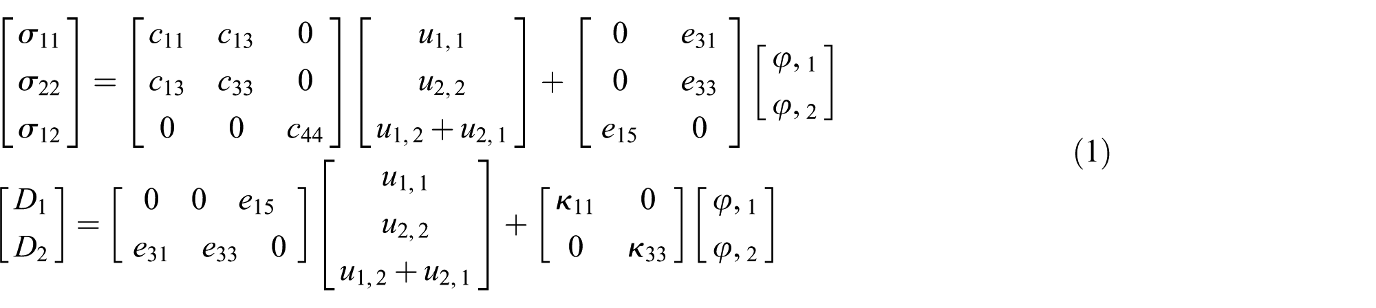
The displacement vector for piezoelectric materials can be written as

In a similar way, the traction vector is
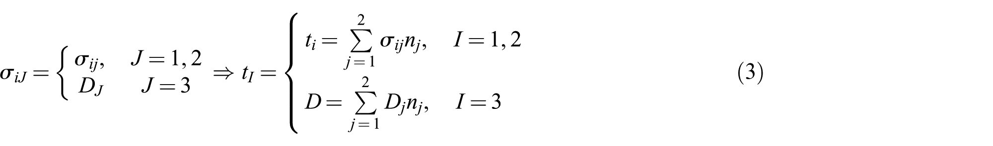
In Figure 6(b), the microstructure subject of the current study is presented. In this microstructure, the basic assumptions are that (i) for two grains which are adjacent, namely grain numbers 9 and 10 (see Figure 6(b)) the value of traction is equal and (ii) these two grains are completely attached to each other as follows

where the values of
The fundamental boundary element equation of displacement for each grain can be written as
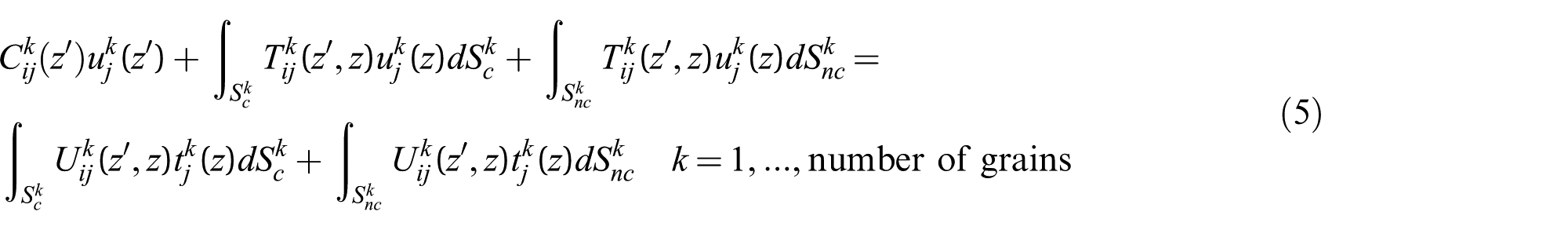
In Equation (5),
It is worth mentioning that the transformation from global coordinate to local coordinate for the boundary condition or free boundary can be done by
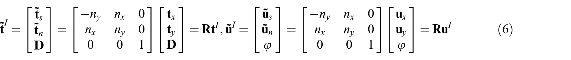
where
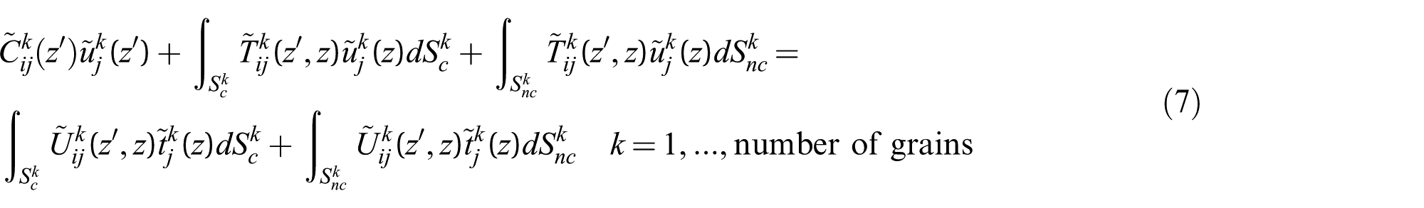
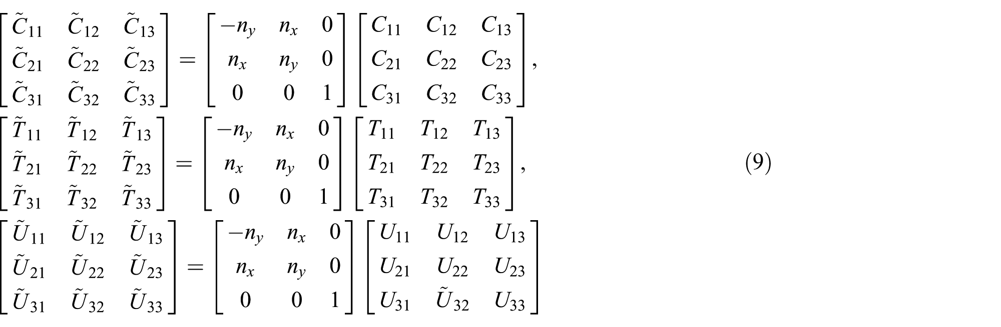
where matrices in local coordinates can be defined in the continuum form

or in the matrix form
5. Cohesive law and crack initiation rules
5.1 Interface condition
In this section, the different conditions at the interfaces will be analysed. Two different statuses will be considered for node pairs as follows.
Undamaged or intact region
Damaged or cohesive region
Cracked region
5.2 Interface equations
In the UR zone the displacement compatibility equations and traction equilibrium equation hold. It is worth mentioning that the traction equilibrium equation will be held in all of the status; however, displacement compatibility equations in the UR zone are different than the ones in CR, that is, for obtaining the displacement jump a cohesive traction-separation law will be introduced.
5.2.1 Undamaged interface continuity equations
When the node pairs are in the undamaged zone, the compatibility and equilibrium equations in local coordinates are the following
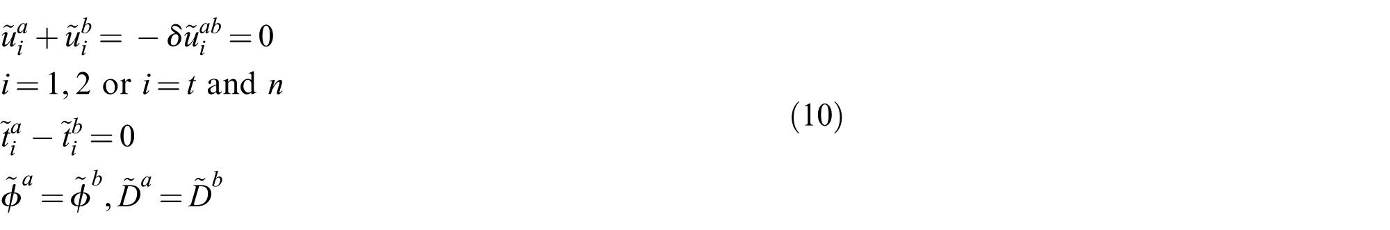
In this equation,
In this equation, 〈.〉 denotes Macauley brackets, which are defined by
5.2.2 Damaged interface continuity equations
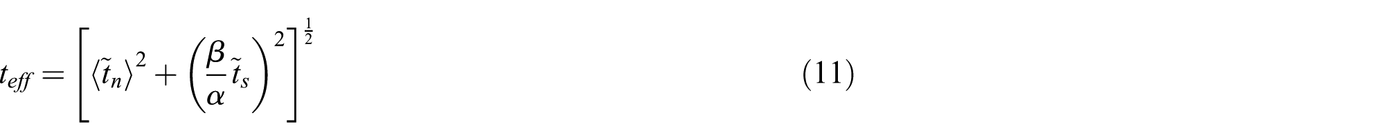
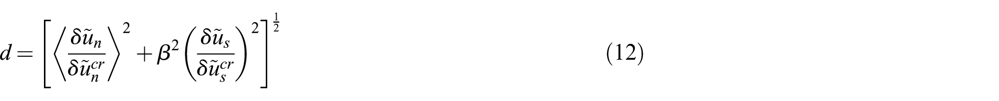
Once effective traction exceeds the maximum value,
In this relation,


Through derivation of the last relation, a cohesive traction-separation law can be approached as follows

In the literature [28,29] this integral equation was suggested as scalar potential

in which

The variable

Let consider Equations (15) and (16): the cohesive traction can be calculated via differentiation of the potential equation and by using the effective opening displacement. The normal and sliding amount of traction in local coordinates can be shown as

The equation that relates α to

The variation of normal and tangential components of traction versus normal and tangential displacement openings is presented in Figure 7. This relation guarantees the accuracy of potential energy in Equation (15), that is, the potential energy or fracture energy are path independent and in normal and tangential modes the fracture energy is equal. However, because of microstructural details, such as interface roughness, the fracture energy cannot be considered independent [56], that is, the fracture energy in normal mode is different from in tangential mode. In order to prove this assumption, the displacement jump can be categorised into normal and tangential components via considering the angle

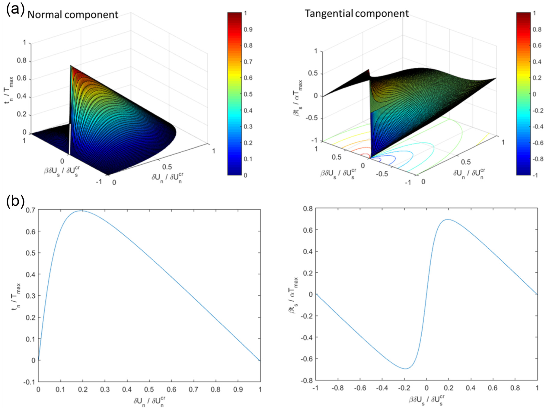
Variation of normal and tangential components of cohesive traction versus opening displacement: (a) three-dimensional plot where the traction change is due to both components of the opening displacement; (b) assigning
Now, let us write an integration relation to show how the total strain energy release rate can be computed
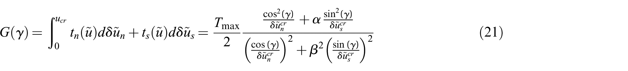
The strain energy release rate for modes one and two can be shown by

It is worth mentioning that the values of
5.2.3 Cracked region
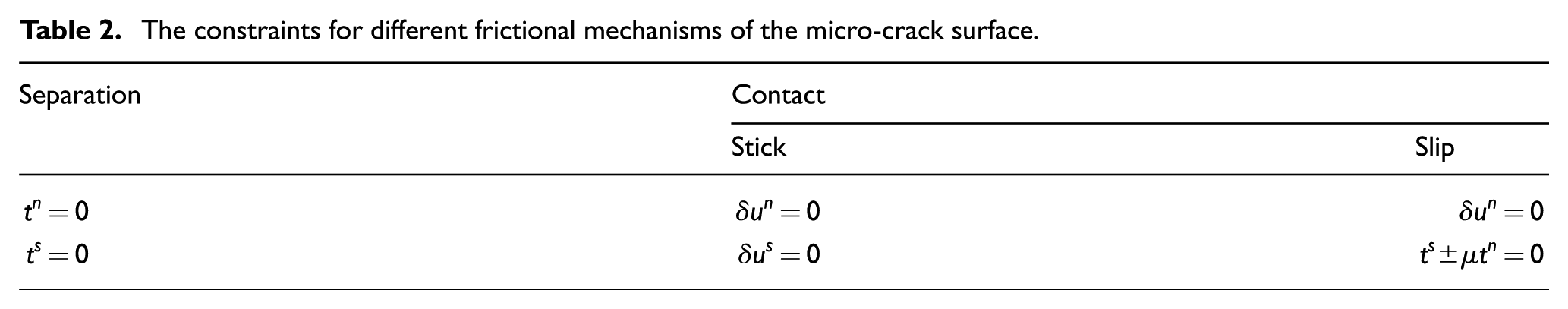
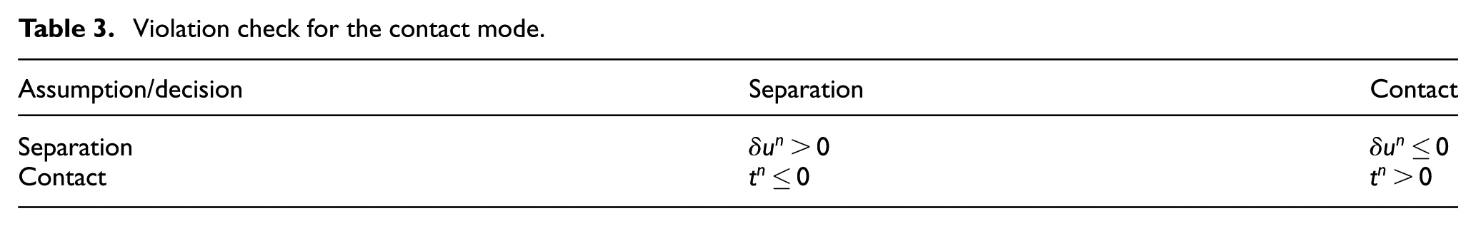
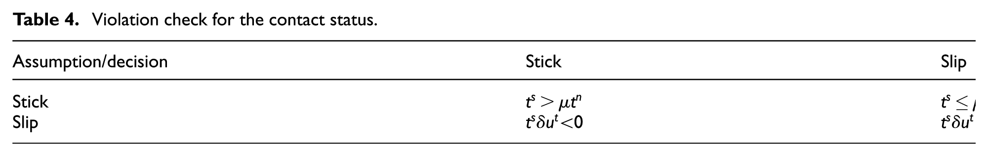
In order to model free micro-cracks, a frictional mechanism is considered. In Tables 2–4 the frictional model, which contains either contact or separation, is presented. Here
The constraints for different frictional mechanisms of the micro-crack surface.
Violation check for the contact mode.
Violation check for the contact status.
6. The evaluation algorithm
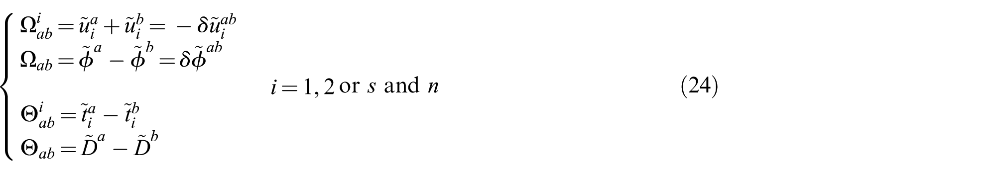
After the image processing procedure in aggregate, the BEM must be applied to all the grains separately. Then, the grain boundary formulation according to different types of regions can be applied in the assembly of the matrix. As was mentioned in the previous section, each grain in the polycrystalline aggregate is supposed to have unique mechanical and electrical properties depending on the different orientation that every grain has. Actually, the orientation of grains in the polycrystalline aggregate was determined via allocating random orientations. The status equations at interface between two adjacent grains namely,
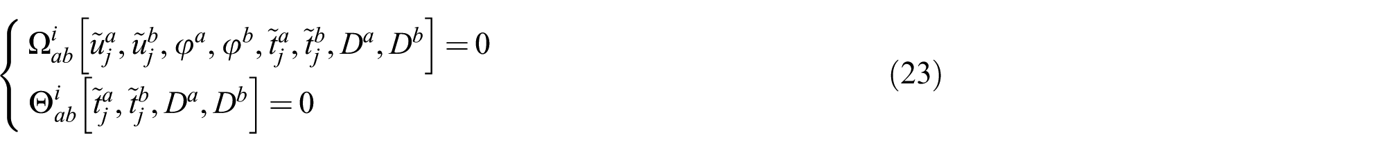
In this system of equations
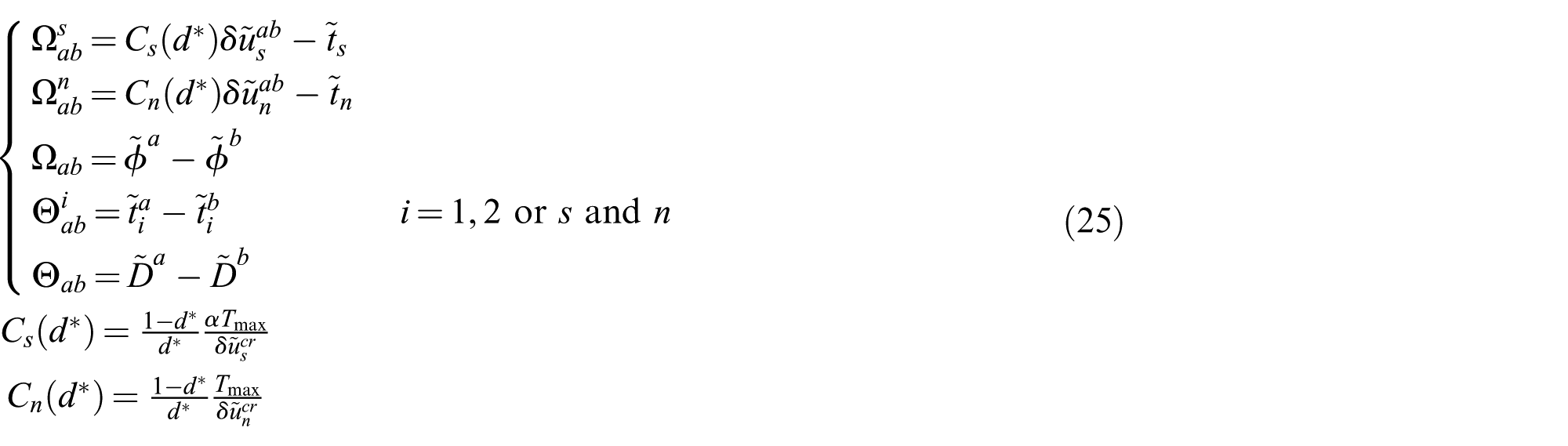
When node pairs enter the cohesive region, these equations can be rewritten by taking into account the cohesive law
We remark that all the variables and equations are defined in local coordinates. In this paper, the uniform displacement boundary condition applied to the microstructure is represented as

A linear relation for one single grain, namely grain number 10 in Figure 6, can be written as follows

Via applying the interface and boundary condition and by using Equation (27) for all the grains in the polycrystalline aggregate, the adaptive system of equations that contains BEM and grain interface equations can be written in a matrix form
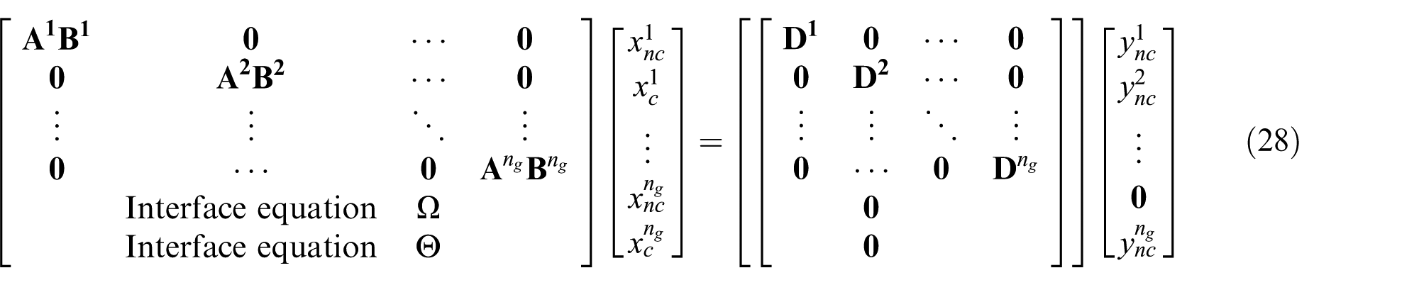
To get this linear equation, the uniform displacement boundary condition has been applied. In Equation (28),
Hence, the linear system of Equation (28) can be extended in another form
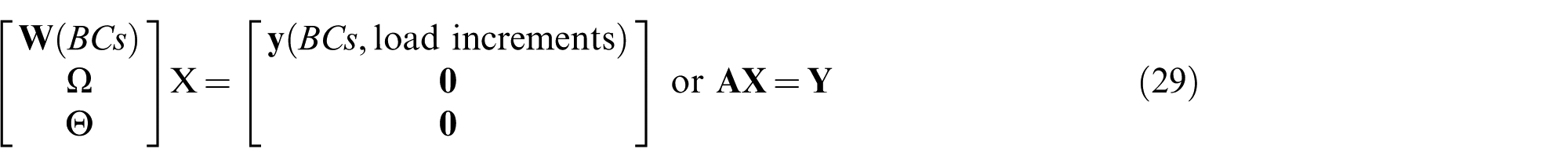
In this matrix,
In order to obtain macro-stress and macro-strain we use averaging theory

where
7. Numerical algorithm and damage evaluations
Let us to explain the numerical algorithms that are used in order to apply the boundary element formulations to the interface equations, damage initiations and propagation procedures. These algorithms have been developed in order to analyse the piezoelectric ceramics from both a micro-mechanical and multi-scale point of view.
7.1 Micro-structural and damage evaluation algorithm
Thanks to the system of linear equation in (28) or (29), it is possible to apply a load to the system. Actually, the external load can be increased incrementally. In the cases where all of the interfaces are in the undamaged status, the micro-structure shows the same behaviour for all the external loads and there are no notable problems in applying the external load; however, this situation is not always available in on the polycrystalline aggregates and, after some particular conditions, the damage will start to be evaluated. More precisely, we define the load increment
We developed a search algorithm in order to find the
In the

7.2 Numerical simulation of micro-damage and the cohesive law without considering contact and frictional effects
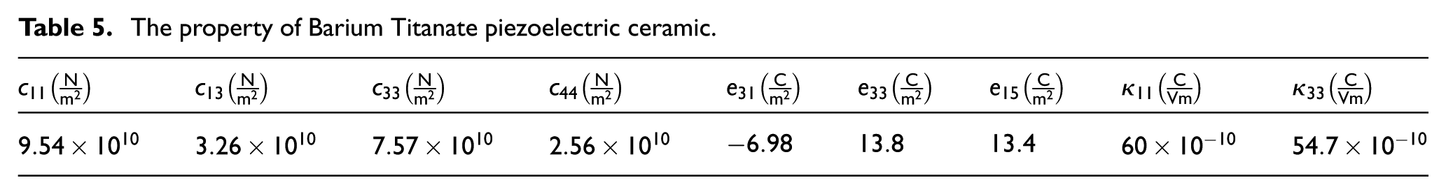
The efficiency of cohesive law and the developed grain boundary formulation will be proved via some numerical examples. We consider a practical example based on the electrical and mechanical properties of barium titanate (see Table 5).
The property of Barium Titanate piezoelectric ceramic.
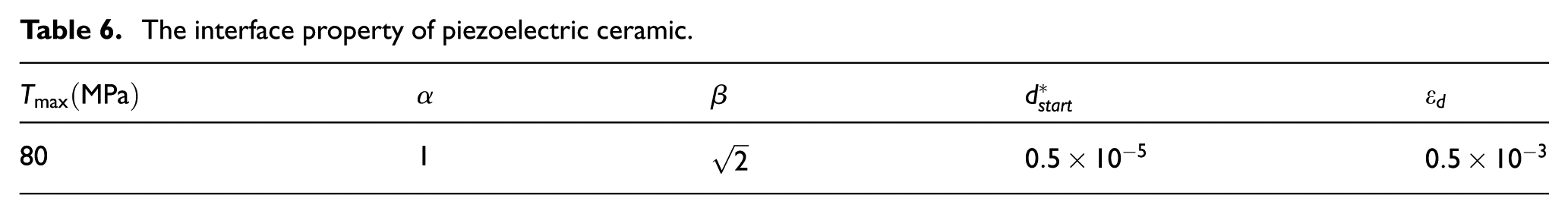
The specified value for parameters was introduced during previous sections and subsections, and can be found in Table 6. The fracture toughness (see [58]) is considered here
The interface property of piezoelectric ceramic.
The uniform displacement boundary condition is applied on the microstructure in the horizontal direction. Figure 8 shows the relation between stress and strain in the microstructure of homogenous piezoelectric ceramic of Figure 9, which is subjected to tensile mechanical load in the horizontal direction (i) by considering the piezoelectric effect and (ii) without the piezoelectric effect. It can be concluded that the piezoelectric coupling has a significant influence on the fracture criteria of aggregates, that is, through considering the piezoelectricity and for a specified amount of strain, the polycrystalline aggregate without the piezoelectric effect can experience more stress. It could be deduced that for a specific strain energy that is entered to the system, the piezoelectric aggregate should be divided between mechanical and electric effects, while in polycrystalline without piezoelectricity this energy can only have influence on mechanical properties. The intergranular fracture criteria of this aggregate, which are subjected to tensile mechanical load in the horizontal direction by considering the piezoelectric effect and without it, are shown in Figure 9. It can be concluded in this figure that by increasing the strain, the crack grows faster and faster.
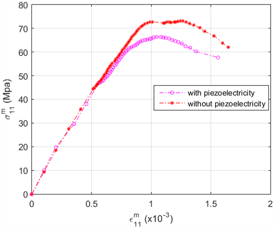
Normal strain and normal stress of polycrystalline aggregate shown in Figure 9 and subjected to tensile mechanical load in the horizontal direction by considering piezoelectric effects and without piezoelectric effects.

The fracture pattern for polycrystalline aggregate under horizontal tensile mechanical load: (a) without piezoelectric effects; (b) with piezoelectric effects.
In this work, the node pairs enter the cohesive zone when the effective traction exceeds the ultimate value of traction. Hence, it could be interesting to know how the traction changes in the node pairs. Figure 10 represents the variation of normal and tangential traction in three different zones of barium titanate polycrystalline subjected to horizontal tensile load. It could be concluded that all of the zones in this figure enter the cohesive zone. As can be seen, these figures are similar to Figure 7, where the normal displacement jump and normal traction have positive values as expected. Moreover, for negative values of tangential traction, the value of the tangential displacement jump is negative and vice versa.
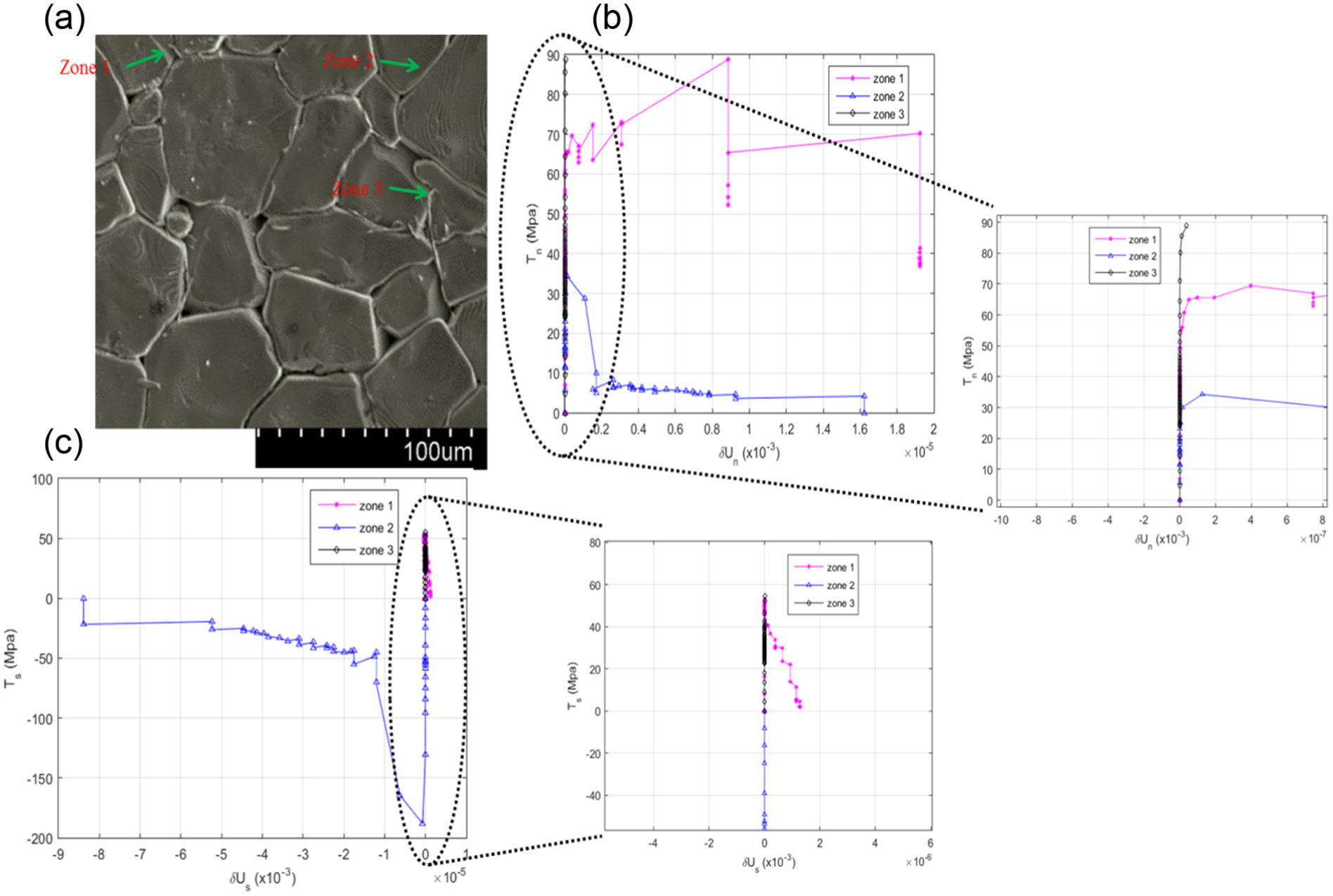
Variation of normal and tangential traction versus normal and tangential displacement jump in three different zones of barium titanate polycrystalline subjected to horizontal tensile load: (a) area in which the components are shown; (b) normal component; (c) tangential component.
7.3 The influence of frictional contact on the mechanical and electrical response of piezoelectric ceramic
The presented results were based on separation and no contact was assumed. In this section, slip and stick conditions are assumed in micro-mechanical grain boundary formulations as well as separation. Let us to compare the results according to the assumption of frictional contact and contact without friction. Figure 11 represents the tension test of piezoelectric polycrystalline aggregate in Figure 9 with and without considering frictional effects. It can be concluded that in the curve with frictional effect the stress has a greater value for the same amount of strain between
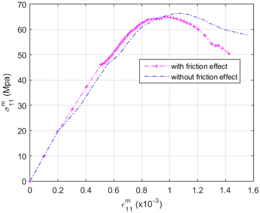
Normal strain and normal stress of piezoelectric polycrystalline aggregate of Figure 9, which is subjected to horizontal tensile load by considering frictional effects and without frictional effects.
Figure 12 demonstrates the modelling in the stress–strain micro-structure of piezoelectric polycrystalline aggregate of Figure 13, which is subjected to a horizontal compression mechanical load, and Figure 13 demonstrates the micro-fracture path. It is obvious in Figure 13 that for a higher value of friction coefficient the micro-crack propagates slower, that is, a higher value of frictional loads opposes the sliding and carrying more loads. In Figure 12, as can be observed, while the polycrystalline aggregate experiences failure and crack propagations, the amount of stress still increases because of inter-lock at the interface and the internal fraction results in intergranular traction higher than zero.
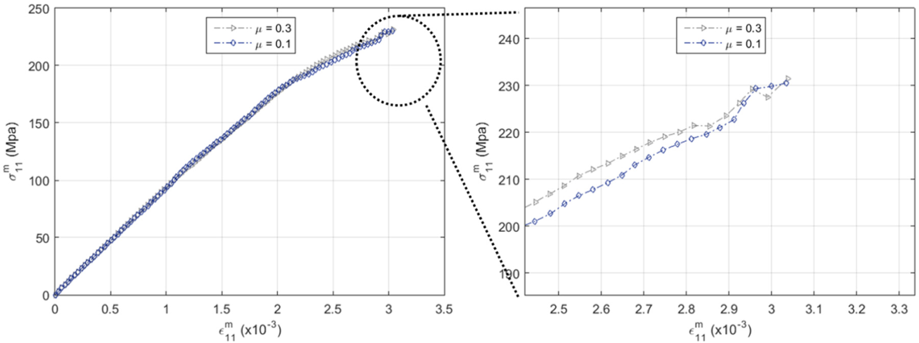
The stress–strain curve of the micro-structure in Figure 13 subjected to compression horizontal mechanical load for different values of friction coefficient.
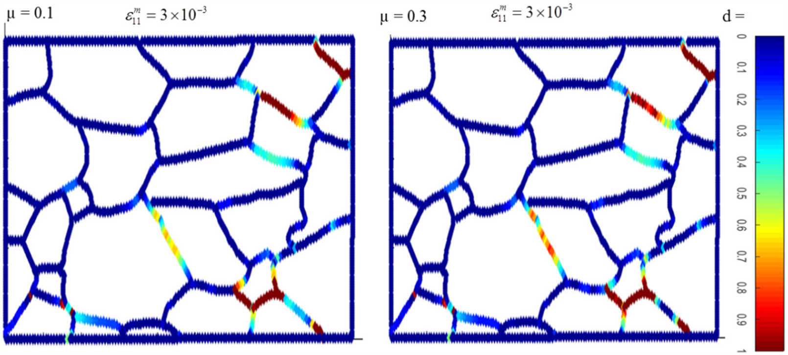
The micro-fracture path of piezoelectric polycrystalline subjected to compression horizontal load for different values of friction coefficient at
8. Conclusions
The crack initiation and evaluation in piezoelectric ceramic according to image processing-based discretisation algorithms have been presented. The micro-structure was obtained through doing some experimental procedures. Then, some comprehensive numerical algorithms have been developed to utilise the geometrical information of pixels, which are allocated to every grain in the micro-aggregate in order to prepare the final model for numerical analysis. The nonlinear grain boundary formulations in different zones, namely the undamaged, cohesive and failure zones, have been combined with the BEM in an adaptive system of linear equations. The image processing-based discretisation algorithms and developed grain boundary formulation were found suitable for investigation of the intergranular micro-fracture in piezoelectric ceramic. Furthermore, the influences of different parameters, such as piezoelectricity effects, friction effects and mechanical loading, have been analysed by using the developed methods. The results of numerical analyses indicate that the image processing-based numerical algorithm is a suitable method for discretising the natural and artificial microstructure of materials. Moreover, considering friction effects in analysis can increase the strength of the materials.
The problem here presented can be conveniently used to study damage and fracture at the micro-level in some mechanical systems, for example pantographic lattices [59]. Numerical tools able to model fracture in this case can be found in [60,61].
Footnotes
Funding
The author(s) disclosed receipt of the following financial support for the research, authorship, and/or publication of this article: This work was supported by the People Programme (Marie Curie Actions) of the European Union’s Seventh Framework Programme FP7/2007-2013/, Grant Number PITN-GA-2013-606878.