
Abstract
A plane problem of fracture mechanics on crack nucleation in a rod-type nuclear fuel pellet is considered. Nuclear reactor fuel pellets in operation may be damaged in various ways; in particular, crack nucleation. We consider a problem for the case of a heat-releasing fuel pellet with cladding: as the heat release intensity increases, zones of heightened stress are formed in the nuclear fuel pellet. The heightened stress will promote the appearance of prefracture bands that are simulated as zones of weakened interparticle bonds of the material. Interaction of prefracture zone faces is simulated by placing bonds between faces that have a specified deformation pattern. The problem of equilibrium of a fuel pellet with prefracture zones is reduced to the solution of a system of singular integral equations. An analysis of the ultimate state of the zone of weakened interparticle bonds of the material is realized on the basis of the criterion of critical opening of prefracture zone faces.
1. Introduction
Heat-generating assemblies are often [1–3] bundles of cylindrical rod-type fuel pellets between whose clearances heat-transfer agent flows parallel to the element axis. Different forms of damage to the heat-releasing elements, in particular, crack nucleation in fuel rods, are possible in the process of a nuclear reactor’s operation.
To ensure reliable operation of fuel pellets, it is necessary to study their stress–strain state and fracture. Problems related to strength of solid nuclear fuel pellets are urgent even today, and undoubtedly interest in them will increase in connection with the existing tendency of an increased energy release in the nuclear fuel. It is appropriate to note the use of new kinds of nuclear fuel, such as mixed-oxide fuel in fast (neutron) reactors.
The problem of crack nucleation and growth in constructions and goods is a significant problem of strength theory [1–26].
The development of design models for studying crack nucleation in fuel pellets is an urgent problem of the mechanics of materials.
Currently, to the author’s knowledge, there are no studies on crack nucleation in rod-type fuel pellets. The considered form of the nuclear system is a bundle of cylindrical rod fuel pellets located in regular lattices (Figure 1). The coolant flows parallel to the pellets’ axes in the gaps between fuel pellets.
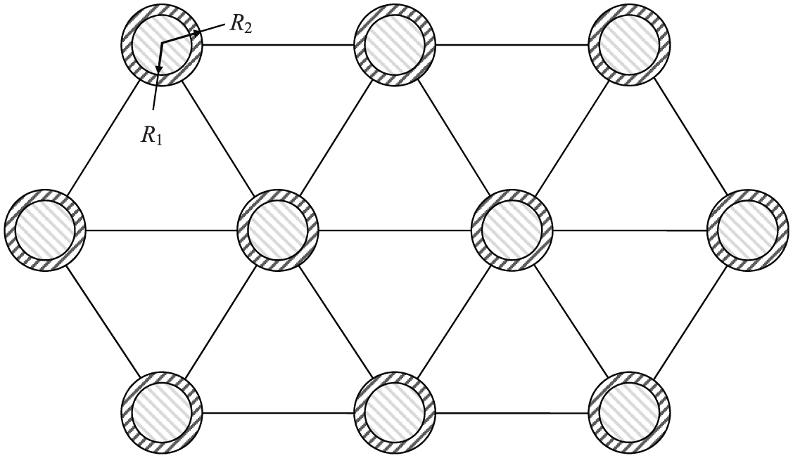
Disposition scheme for fuel elements in the nuclear system of fuel elements and coolant.
In recent years, in the Russia Federation, a fabrication plant for mixed-oxide fuel for fast reactors has been built and commissioned. In other countries, such plants are being built. The nuclear fuel is a mixture of plutonium and uranium dioxides. This fuel is used in BN-800 reactors on fast neutrons in the fourth block of Beloyarsk Nuclear Power Plant. In future, it is expected to use this fuel in more powerful power unit BN-1200 reactors [27]. It should be noted that the considered nuclear fuel is assumed to be an elastic material. Therefore, the proposed model is valid for most fuel elements currently used in nuclear reactors.
The development of methods for studying crack nucleation will promote serviceability increase of heat-releasing elements, by enabling reasonable selection of structural parameters of elements at the design stage.
The goal of this paper is to develop a mathematical model of crack nucleation in heat-releasing fuel pellets in nuclear reactors.
2. Statement of the problem
A plane problem of fracture mechanics is considered for a fuel pellet occupying a domain in the form of a circle of radius R1. The geometry of the fuel pellet is delimited by a circle of radius R1 and the cladding is delimited by circles of radii R1 and R2. Let the considered heat-releasing element occupy a circle of radius R1 in the plane z = x+ iy, centered at the origin of the coordinates, bounded from outside by the circumference L1, and let the cross-section of the cladding occupy, in the same plane, a ring bounded from outside by a circumference L2 of radius R2, whose center coincides with the center of the circumference L1, and bounded from inside with the circumference L1 of radius R1.
In the course of operation of the nuclear reactor, different forms of damage to the fuel pellet material are possible; in particular, crack nucleation. Let us consider a problem for a rod-type fuel pellet with cladding for the case when zones of heightened stresses appear as heat release intensity q in the element increases. The zone of heightened stresses will promote appearance of prefracture zones that are simulated as areas of weakened interparticle bonds of the material.
It is considered that the plane deformation conditions are fulfilled. To simplify the problem, we consider the double-layer structure in the form of “fuel rod cladding.”
The initial axially symmetric problem for the fuel rod is violated because of the pressure of the coolant and the presence of the prefracture zones. The location and size of the first prefracture band are unknown beforehand and are found in the process of solving the problem.
A generalized assumption on plane deformation is accepted. Prefracture bands are described by a cohesive zone form of the Leonov–Panasyuk type brittle model [28]. Recall that in Leonov–Panasyuk’s generalized brittle model, the normal and shear cohesive forces are accepted as constant and are equal to two parameters of the material,
We will assume that the fuel rod is so large that in its middle part the stress pattern is identical at all its sections perpendicular to the axis of the fuel’s cylinder.
In the great majority of cases, it is attempted to create close contact (adhesion) between the core and the cladding to improve heat conductivity and ensure optimum heat sink conditions. The absence of such contact may lead to the appearance of large temperature gradients and violation of integrity of the cladding and core. However, the creation of contact between the core and cladding almost always creates some difficulties as the core and cladding are manufactured separately from completely different materials. If there is a gap between the fuel and the cladding, the cladding should have considerable strength in order to resist destructive action due to external pressure of the coolant. Thin claddings ensure neutron economy, but they are not strong enough and should have additional support in order to resist the external pressure of the coolant. Under close mechanical contact of fuel and cladding, when friction forces between fuel and cladding are great, the fuel may serve as a support for the cladding. From the side of the fuel, the forces arising in the fuel because of thermal stresses act on the cladding. These forces may be balanced; then fuel pellets are subjected to uniform two-axial stress. This is possible only in the case when the gap between the fuel and cladding is identical along the entire length of the fuel pellet. Thus, we can assume that the plane deformation conditions are fulfilled. The case when there is a gap between the fuel and cladding is not studied.
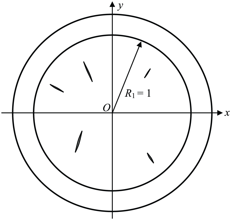
In the deformation process, at some points of the domain occupied by the material of the fuel pellet there may appear prefracture zones, which are simulated as zones of weakened interparticle bonds of the material. As the indicated zones (interlayers of stressed material) are small compared with other parts of the element, we can mentally remove them and replace them by cuts whose surfaces interact by some law corresponding to the action of the removed material, where the material of the fuel pellet is deformed beyond elasticity. Let the fuel pellet’s material have an arbitrary number N prefracture zones (Figure 2). At the centers of the prefracture zones (plastic flow zones under constant stress) we place the origin of the local system of coordinates xkOkyk, whose axes xk coincide with the lines of prefracture zones and make angles αk with the axis x (Figure 2).
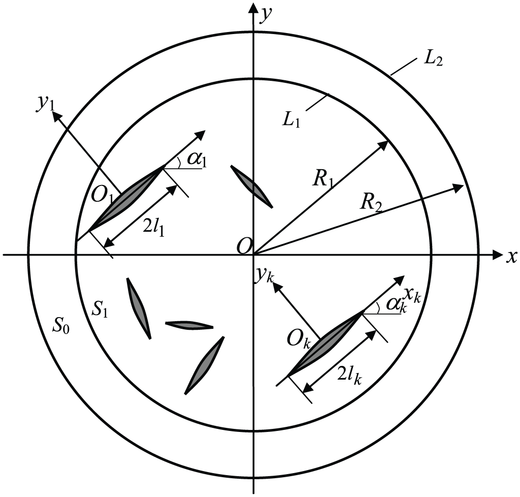
Design scheme of the crack nucleation problem for a rod-type nuclear fuel pellet.
The interaction of prefracture zone faces is simulated by placing the bonds with the specified deformation pattern between the faces. Under the action of external forces in bonds connecting the prefracture zone faces, there will arise constant normal, σs, and tangential, τs, cohesive stresses. Thus, normal and tangential stresses numerically equal to σs and τs, respectively, will be applied to the prefracture zone faces. Herewith, the locations and sizes of the prefracture zones are unknown beforehand and should be determined in the course of solution of the problem.
Experimental research [26, 29, 30] on the appearance of domains wherein the material is deformed beyond elasticity show that, at initial loading stages, the prefracture zones have the form of a narrow stretched layer, and then, as the load increases, there suddenly appears a secondary system of domains that contain a material with partially violated bonds. Based on this research [26, 29, 30], at the initial stages of loading, it is accepted that the prefracture zones extend along a straight line. The number of prefracture zones is given in advance. Allowance for the curvilinearity of prefracture zone bands significantly complicates the problem of crack initiation in nuclear fuel, and this is not considered in this paper. For mathematical description of defect nucleation as a crack in the material of the heat-releasing element in the course of operation, in the considered case, we arrive at a plane problem of thermoelasticity for a two-layer cylindrical structure when the element’s material has prefracture zones (plastic flow zones).
The domain of the fuel pellet bounded by the circumference L1 we denote by S1; the domain of the cladding by S0. As is well-known, an increase in the profitability of nuclear reactors is connected with an increase in burn-out of nuclear fuel. The burn-out of the fuel is limited by the changes that occur in the materials of a fuel pellet during operation in the reactor and reduce to fracture of the fuel pellet. The life time of a fuel pellet may vary, for various reasons, for example, corrosive failure of the cladding. The problems associated with corrosive failure of the cladding are solved by selecting a more suitable cladding material, improved construction, etc. Crack initiation in the core material is an important reason for failure of fuel pellets. Crack initiation reduces to a loss of mechanical strength and fracture under the action of internal stresses. We will consider that the materials of the element and the cladding are isotropic and homogeneous with non-identical mechanical properties.
Let us consider a fracture mechanics problem of crack nucleation in a fuel pellet strengthened with cladding provided that the heat release intensity (the specific capacity of internal heat sources) in the element q is uniformly distributed in the volume.
The stresses in the material of the fuel rod are determined by the second derivatives of the function U (which is called the Airy stress function) in the following form:

In the case under consideration, the boundary value problem for stress function U has the form


on the prefracture zone faces

Here the function f0(t) describes the action of coolant on the external surface of the cladding; α is the factor of linear temperature expansion; E is the modulus of elasticity of the fuel pellet; λc is the heat-conduction coefficient;
To determine the intensity values of the internal heat sources under which crack nucleation happens, the problem statement should be completed with the criterion of crack appearance (rupture of interparticle bonds of the material). As such a criterion, we accept the condition of critical opening of prefracture zone faces:

where
This criterion enables us to determine the parameters of a two-layer cylindrical structure for which a crack appears in a fuel pellet.
3. Solution method
Using Kolosov–Muskhelishvili complex potentials [31], the problem under consideration is reduced to finding two pairs of complex functions Φ j (z) and Ψ j (z) (j = 0, 1) of the complex variable z = x+ iy analytic in domains Sj (j = 0, 1) and satisfying the boundary conditions:


on the prefracture zone faces

Here,
Under the action of loading, at the expense of differences in elastic properties of the materials of the fuel and the cladding, some self-balanced system of forces acts on the fuel pellet from the side of the cladding.
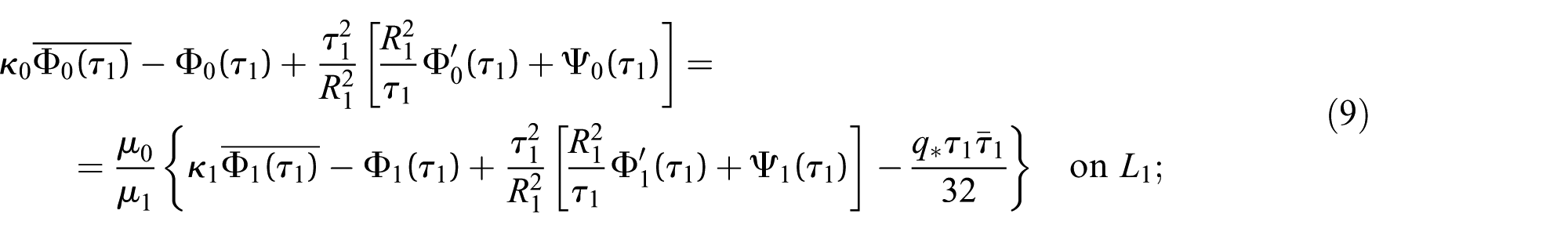
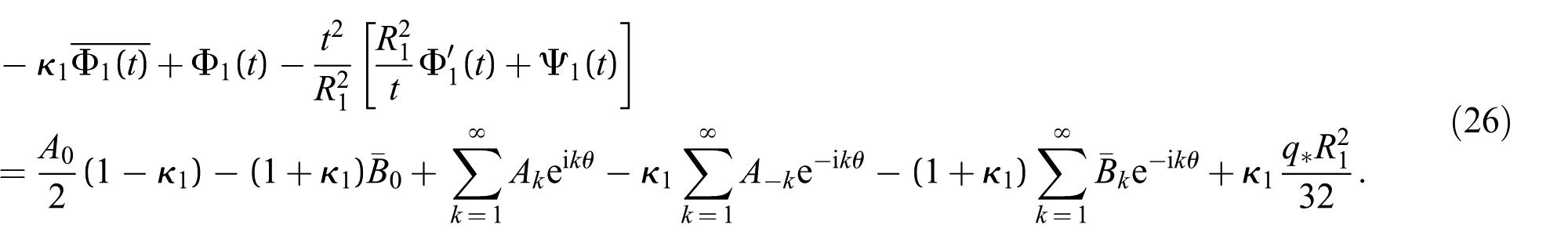
Considering for now this load on the element given formally, we find complex potentials Φ1(z) and Ψ1(z). Denote by N1– iT1 the left-hand side of boundary condition (9) and expand it on the contour L1 in Fourier series:


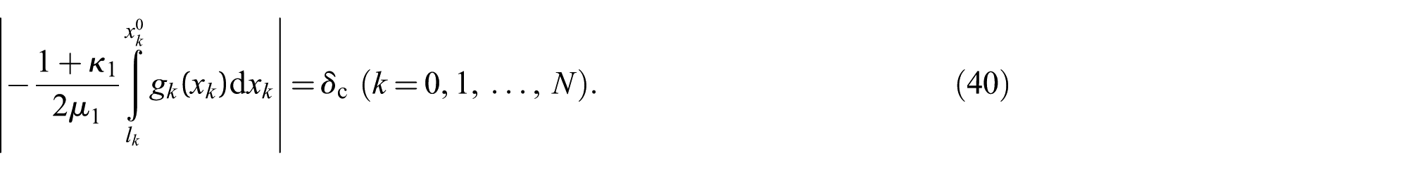
According to boundary conditions (8), (9), and (11) for determining the potentials Φ1(z) and Ψ1(z), we have, on the contour L1, the boundary conditions

on the segments

We look for the solution of the boundary value problem (equations (13) and (14)) in the form

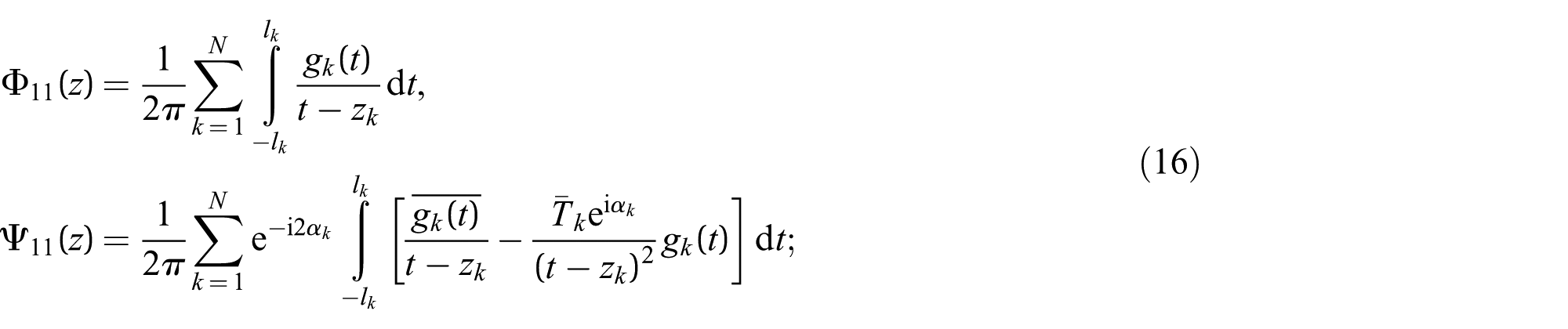

The potentials Φ12(z) and Ψ12(z) are regular in the entire circle of radius R1; they should be determined from the solution for an entire circle according to boundary condition (13); to determine the unknown functions gn(x) (n = 1, 2, …, N), the boundary conditions (14) on the segments
In what follows, all linear sizes (x, t,
We satisfy by functions (15) and (16) the boundary conditions on the faces of the plastic deformations zones and obtain a system of singular integral equations with respect to unknown functions gn(x) (n = 1, 2, …, N)
Here,
Boundary condition (13) admits an auxiliary problem for an entire circle:

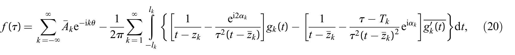

The solution of auxiliary problem (19) is given by Muskhelishvili’s formulas:


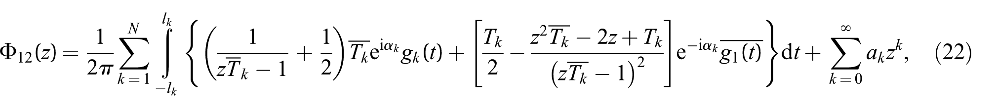
After substituting function (20) in formula (21) and changing the integration order, as well as using the residue theory, we finally get:


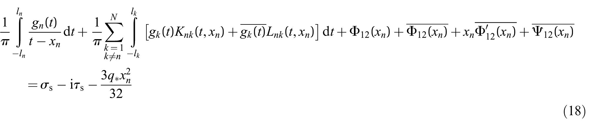
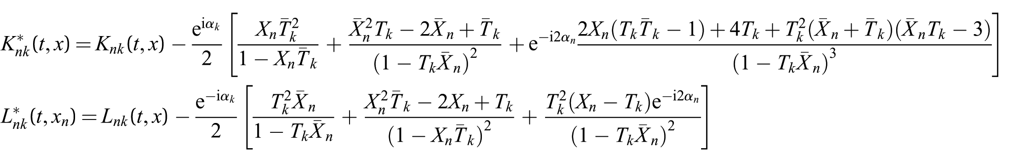
Substituting the found values of Φ12(z) and Ψ12(z) into equation (18), we finally get a system of singular integral equations with respect to the unknown functions gn(x) (n = 1, 2, …, N):
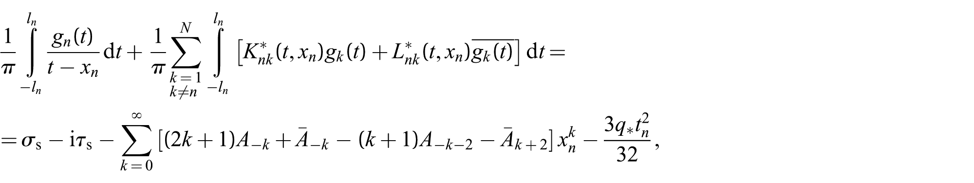

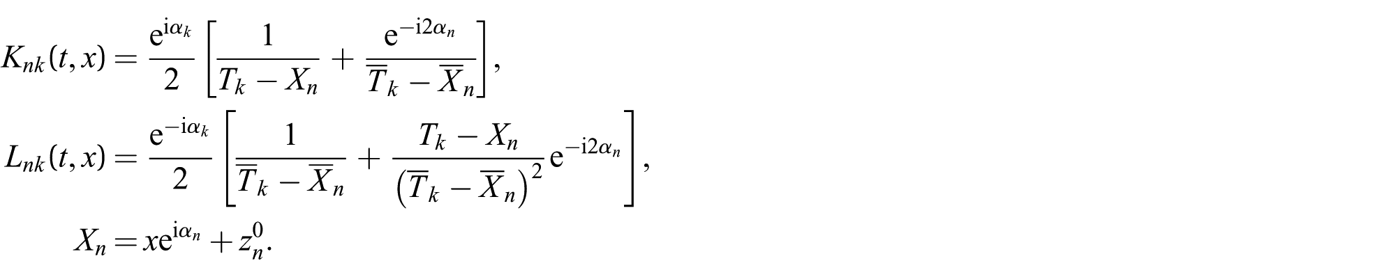
Here,
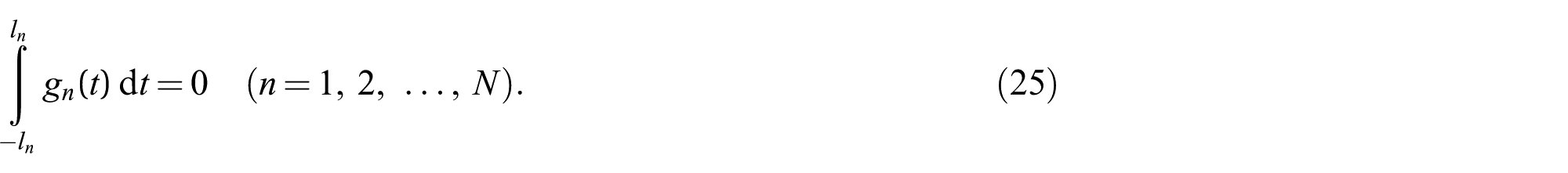
To the system of singular integral equations (24) it is necessary to add the conditions following from the physical sense of the problem:
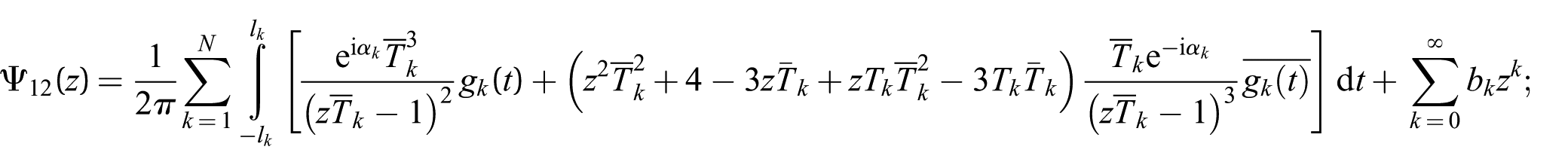
Knowing the potentials Φ1(z) and Ψ1(z), describing the stress–strain state of a fuel pellet, we find the following value:
Here,
When constructing the solution for a fuel pellet, we considered the coefficients Ak (k = 0, ±1, …) to be given, but still unknown. They should be determined in the course of the solution of the boundary value problem. To find them, we use the solution of an elasticity problem for a cladding. To determine the potentials Φ0(z) and Ψ0(z) and the coefficients Ak (k = 0, ±1, …), based on relations (7), (9), and (11), we have the following boundary conditions:


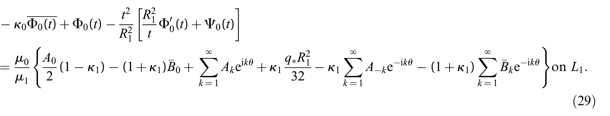
The functions Φ0(z) and Ψ0(z) are regular interior to the domain S0, and therefore may be expanded in Laurent series. Thus, interior to the domain S0, we will have

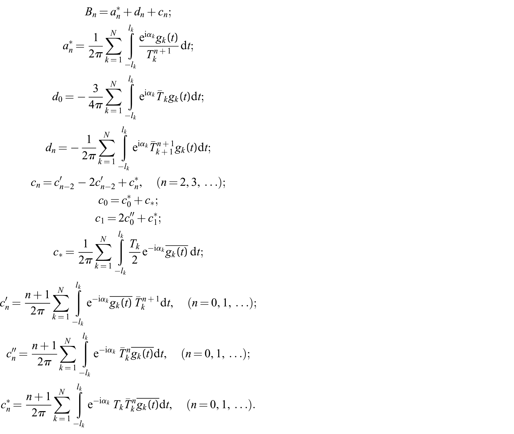
Satisfying by functions (30) the boundary conditions (27) to (29) and comparing the coefficients under identical powers of exp(iθ) in the left- and right-hand sides of boundary conditions (27) to (29), after some transformations we get:


From equations (31) and (32) we find


The last relations admit expression of the coefficients Ak (k = 0, ±1, …) by the values Bk, which are dependent on the unknown functions gn(x) (n = 1, 2, …, N). Conversely, the system of singular integral equations contains the unknown coefficients Ak.
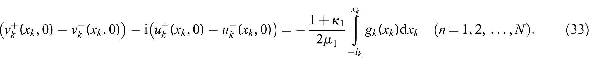
If we represent the unknown functions

then from the system of N complex singular integral equations, after separation of real and imaginary parts, for finding
For the right-hand side of relation (17), we have
Thus, the infinite system of algebraic equations and the system of singular integral equations should be solved jointly.
Now we pass to algebraization of the mentioned system of equations.
4. Algebraization of main resolving equations
By means of change of a variable, we reduce all integration intervals to one segment [−1, 1]. For that we put

Then the system of singular integral equations (24) and the additional conditions (25) are written in the form
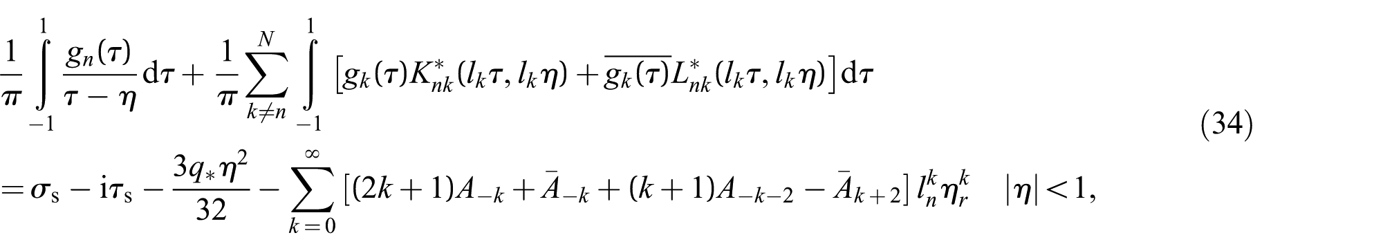
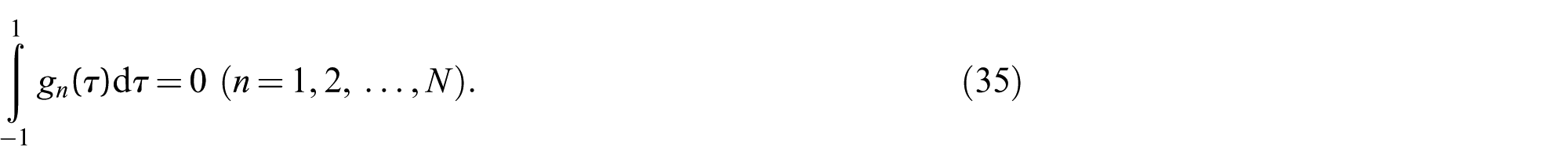
In equations (34) and (35), for convenience, for the unknown functions, we preserved the previous designations. We represent the solution of system (34) under conditions (35) in the form

Here, the functions
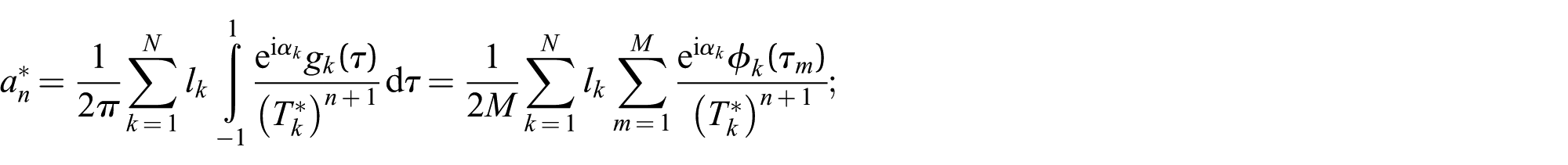
By means of Gauss–Chebyshev-type quadrature formulas [32–34], the system of integral equations (34) under conditions (35) is reduced to the system of N×M algebraic equations with respect to the unknowns
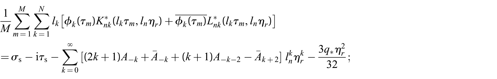

Here,

Gauss–Chebyshev-type quadrature formulas admit complete algebraization of the related systems of equations mentioned already, by means of the relations


The mentioned systems are not closed yet.
To preserve the design scheme, the solution of the system of singular integral equations was sought in the form of equation (36), that is, it has root singularities at the end of the prefracture zone. In fact, within the model of the prefracture zone, with interfacial bonds between faces, the stresses in the fuel pellet are everywhere finite, including at the tip of prefracture zone.
It would be well to look for the solution of the problem in the class of everywhere-bounded functions (stresses). The condition of stress limitation at the tip of the prefracture zone helps to determine the location of unknown sizes of prefracture zones. We complete the obtained main systems of algebraic equations by the stress limitation conditions in the vicinity of prefracture zone tips:


The system of algebraic equations (31), (32), (37), and (38) is closed. Because of the unknown lengths of the prefracture zones, the system of combined algebraic equations is not linear. Its numerical solution enables determination of the coordinates of the tips (location) and the sizes of the prefracture zones; that is, the values
Obviously, having determined the coordinates of the tips of all prefracture zones, using the known formulas of analytic geometry one can find the coordinates
Knowing the function gn(x), one can find the stress–strain state of a fuel pellet and its cladding.
5. Limit level of heat release intensity
After finding the sought-for functions

where
As a result of these calculations, the lengths of the prefracture zones were determined as a function of the intensity of the internal heat sources and the parameter R1/R2.
By means of the criterion of critical opening of prefracture zone faces, the condition determining the limit level of the heat release intensity in the element was found for each prefracture zone. The value of heat release intensity that caused appearance of the kth crack is determined from the relation
The critical value of the intensity of the internal heat sources in the fuel pellet will be minimal among

Because of the unknown quantities lk (k = 1, 2, …, N), the combined resolving system of equations becomes nonlinear. To solve it, we used the successive approximations method. We solve the combined system under some certain values
At each approximation, the combined system of equations was solved by the Gauss method, choosing the principal element for different values of M.
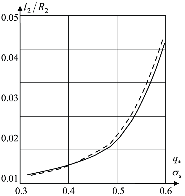
The calculation results are given in Figures 3 to 7. The dependences of the prefracture zone length lk/R2 (k = 1, 2, 3) on the dimensionless value
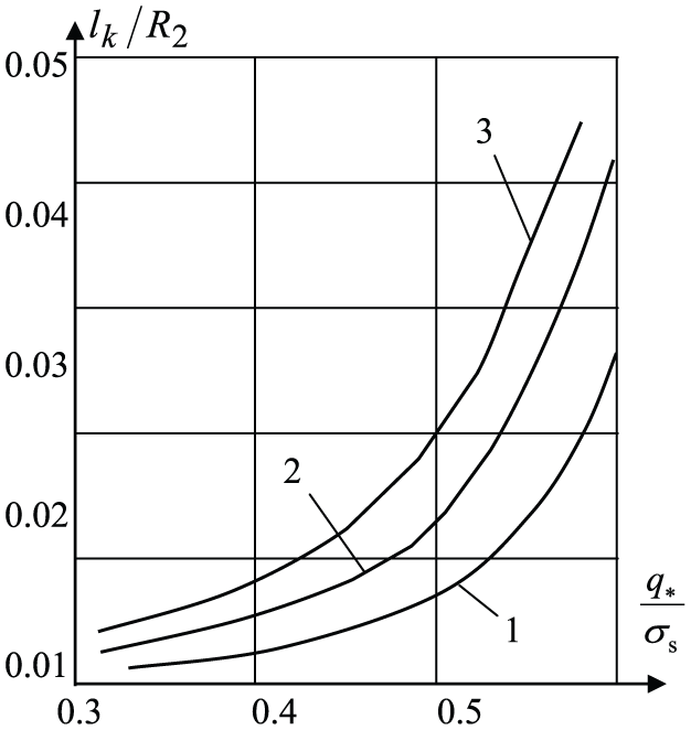
Prefracture zone length lk/R2 (k = 1, 2, 3) as a function of the dimensionless value of the intensity of internal heat sources for different orientation angles: α1 = 15°; α2 = 30°; α3 = 45°.
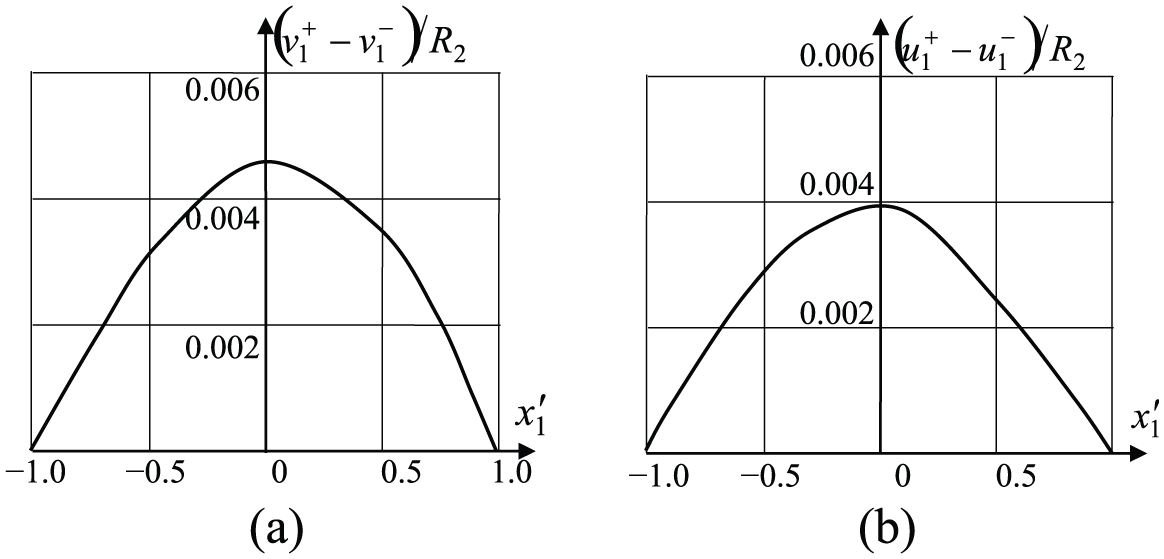
Normal and tangential components of the displacement vector as a function of dimensionless coordinates
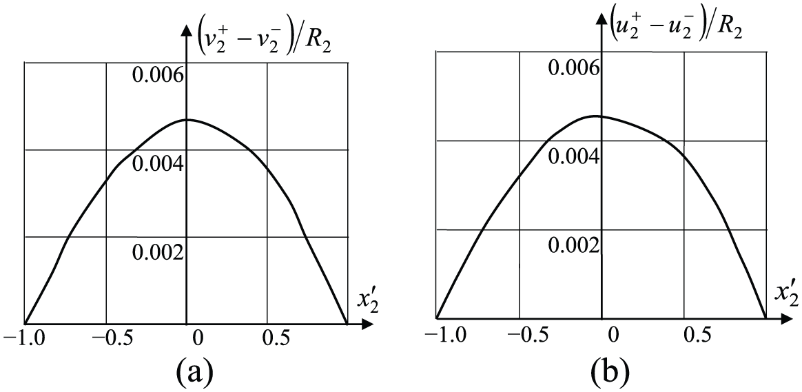
Normal and tangential components of the displacement vector as a function of dimensionless coordinates
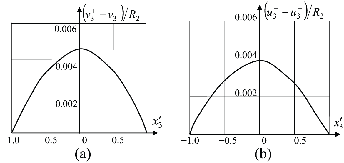
Normal and tangential components of the displacement vector as a function of dimensionless coordinates
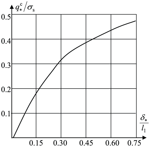
Critical intensity of internal heat sources as a function of the relative opening
Graphs of the distribution of the normal
The stress components
Finally for stresses

where the constant C is calculated from the condition

where FD is the area of the domain D.
The dependence of the critical intensity of the internal heat sources in the material of the fuel pellet
The obtained algebraic system of equations of the problem allows us to get the solution with any accuracy given beforehand. The convergence of the procedure of numerical solution using singular equations is discussed in many papers [32–34]. Numerous studies show that the number of collocations M should not be less than 20. Since M = 20, the values of the coefficients of the function of normal displacement are not significantly changed. In calculations, M was equal to 30.
Thus, a joint solution of the obtained algebraic systems and the limiting condition (40) enables (under the given characteristics of the material of the fuel pellet) us to determine the critical value of the intensity of the internal heat sources and the sizes of the plastic flow zone for the limit equilibrium state under which crack nucleation happens.
Through calculation of the results for the case N = 5,
Calculation results for the prefracture bands (N = 5).
The evolution of the length of the prefracture band on the number of iterations is illustrated in Figure 9. Here, the solid line is the solution for 10 iterations; the dashed line is the solution for three iterations.
Evolution of the length of prefracture band as a function of the number of iterations.
6. Single checks
No heat source, infinite cohesive stress, same material properties for fuel and cladding
In this case,
No heat source, infinite cohesive stress, different material properties for fuel and cladding
In this case,
Heat source and external pressure, infinite cohesive stress, different material properties for fuel and cladding
In this case, the locations and sizes of the prefracture zones should be given beforehand. The solution is sought in the class of unbounded functions (stresses) in the vertices of the prefracture zones. Conditions (39) drop out. The system of algebraic equations is linear and is solved by the Gauss method. In these particular cases, the results of the solution completely and accurately coincide with the analytic and numerical solutions of these problems reported in the literature.
At some stage of loading, simultaneous existence of the plastic flow zone and crack nucleation in the fuel pellet is possible. The solution method in this case combines the simultaneous account of damages and cracks for the end zones of plastic deformations.
7. Conclusions
In practice, the use of nuclear fuel pellets in nuclear reactors shows that at the design stage it is necessary to take into account the cases when cracks may be initiated in an element. In this circumstance, it is necessary to perform limit analysis of fuel pellets in order to establish limiting intensities of heat release under which crack nucleation occurs in the fuel pellet. The size of the limit zone of the weakened interparticle bonds of the material under which crack nucleation happens should be considered in determining the design characteristics of the material of a fuel pellet. Based on the suggested calculation model, which takes into account the occurrence of damage (plastic flow zones) in the material of a nuclear fuel pellet, a method to calculate the parameters of the heat release element under which crack nucleation happens was developed.
The developed mathematical model of cracking in a fuel pellet, in the author’s opinion, may be generalized in future for more complicated phenomena of the behavior of fuel rods that occur during reactor operation.
Footnotes
Funding
The author(s) received no financial support for the research, authorship, and/or publication of this article.