
Abstract
The interplay between mechanics and geometry is used to construct a theoretical framework able to describe the class of three-dimensional objects that can be fabricated from suitable planar designs by using relaxation of pre-strains/stress in ultra-thin films. Small deformations and large rotations are used here to model the elastic relaxation into various three-dimensional shapes. Over the kinematics associated with the designed mid-surface, a small perturbation of Love–Kirchhoff type is considered in order to deduce the design plate-to-shell equations for orthotropic materials with an important pre-stress/strain heterogeneity. The resulting equations for the efforts average and efforts moments provide the supplementary equations to compute the in-plane pre-strain/stress. In particular, for materials with a weak material transversal heterogeneity the moments equations involve only the thickness, the curvature tensor, and the pre-strain/stress moments. Special attention is devoted to materials that can be obtained by layer-by-layer crystal growth (molecular beam epitaxy), which posses an in-plane isotropic pre-strain. We have found that a rectangular plate could relax both into a cylindrical surface or on a part of a sphere in which case it should have a small diameter with respect to the sphere radius. In both cases, the theoretical estimates have been compared with the experimental realizations and finite-element numerical computations and we found very good agreement among all of them. In addition, for the cone geometry we found that the design is not possible from an isotropic pre-stress with an in-plane homogeneity. However, the 3D finite-element computation of the relaxed surface with a (necessary) non-isotropic pre-stress obtained from the theoretical estimates matches remarkably well the designed conical surface.
1. Introduction
Among the advanced methods for semiconductor crystal growth, molecular beam epitaxy (MBE) provides very fine tuning of the thickness and/or material composition, but in order to obtain almost defect-free materials, the lattice mismatch between the planar template and the grown crystal should be as small as possible. Even when this mismatch is small, the pre-strain induced by the lattice mismatch can manifest through the creation of defects and/or bending of the layered structure, a common situation when the respective thicknesses of the layers are of the same order of magnitude. From a practical point of view, the bending process may be beneficial at very low thickness as one can use it to design various three-dimensional (3D) objects starting from planar pre-strained templates. Initiated by the group of Prinz [1, 2] the control of the bending process was essentially restricted to ribbons, curls, and/or similar constant curvature objects [3–5], mainly one-dimensional (1D).
As semiconductors are anisotropic elastic/fragile materials, the study of the equilibrium shape for a bilayer plate with X3 -dependent pre-strain/stress can be formulated as a classical linear elasticity problem as long as one is interested in small perturbations theory (small displacement, small strain, and small rotations) of a given but fixed reference configuration. However, this classical approach has at least two main drawbacks: (i) it cannot recover experimental results illustrated for instance in [5] for the relaxed configurations that do not fit the small perturbation theory, which is a situation frequently encountered in applications; and (ii) it cannot answer the important practical question which is the two-dimensional (2D) shape that relaxes toward a given 3D given surface/object? While the former drawback should be a benchmark for various approximate and/or exact nonlinear models for elastic plates/shells, the latter question fits the framework of topological optimization within the framework of shell theory.
Recent work in [6, 7] on various approximations of the 3D elasticity with incompatible pre-strain/stress provided a hierarchy of nonlinear elastic models that fulfill the requirement (i) but which cannot solve the design problem stated in (ii). From a different perspective, the pioneering work in [8–10] built a theory of incompatible surface growth that includes geometric nonlinearities and finite stretch, both core ingredients for a realistic description of the relaxed shapes.
There are several approaches in deducing (2D) plate models from (3D) elasticity equations. While some of them are based on ad hoc hypotheses (see Ciarlet [11] for a review), others use a mathematical formalism. The latter are based on Gamma convergence (see, for instance, [12–15]) or use an asymptotic expansions on the 3D weak formulation (as in [16–18]) or on the 3D differential formulation. This last method was used to derive various consistent finite-strain plate models for different magnitudes of the in-plane and normal surface loads (as in [19–21]) or without any assumption on magnitudes of surface loads (see [22, 23]). Another way of deducing the asymptotic model, used by Steigmann and his coworkers [24–30], is based on the expansion of the potential energy for conservative boundary-value problems. In all of these approaches there are two main assumptions that prevent the use of these models for pre-stressed structures: (i) the a priori scaling of the in-plane and normal surface loads and (ii) the regularity assumptions on stresses supposed to be smooth with respect to the thickness variable. Indeed, the deformation of the structure is due to the pre-stress only with vanishing surface loads, while for technological reasons the pre-stress is discontinuous with respect to the thickness.
The aim of this article is to construct a theoretical framework able to enlarge the class of 3D objects that can be fabricated from suitable planar design by using relaxation of pre-strains/stress. More precisely, given a shape of a shell’s mid-surface (described as a 3D image of a plate mid-surface) we are looking for the shell’s thickness and for the pre-strain/stress such that the plate will relax (with small deformations) into the given shell as the effect of pre-strain/stress exclusively. As we focus on brittle–elastic materials (as semiconductors) the small deformations assumption is here a technological restriction and not a mathematical simplification. However, to describe complex 3D relaxed shapes, large rotations are mandatory.
This article is organized as follows. Section 2 introduces the kinematics of the plate-to-shell deformation. In particular, over the kinematics associated with the (exact) target mid-surface, we consider a small perturbation of Love–Kirchhoff type, which ensures an approximative designed kinematics. In Section 3, we present the plate-to-shell equations for orthotropic materials with a general dependence of the elastic coefficients on the thickness variable and with an important pre-stress/strain heterogeneity. As for the materials we discuss in this article the material properties are almost homogeneous, we also discuss the case of a weak material transversal heterogeneity, situation in which the system of equation is considerably simpler. In Section 4, we apply the proposed theoretical framework to the small-diameter spherical surfaces, the (arbitrary) cylindrical surfaces and the conical surfaces, all of them in the case of isotropic elastic materials with isotropic in-plane pre-stress. We compare the experimental realizations of the first of these cases both with the theoretical estimates and with 3D finite-element numerical computations and find a good agreement between all of them.
2. Kinematics of the plate-to-shell deformation
In this section, we introduce the kinematics of the plate-to-shell map, further discussed in detail in this article. The starting point is the designed mid-surface of the shell that will be given through a purely geometric transformation. We point out that not only is the surface designed but also its associated transformation. The main restriction is that the corresponding (membrane) deformation should be small in a certain sense, precisely defined in the following. The kinematics of the plate deformation involves the classical Love–Kirchhoff assumption, that is, the normal to the plate mid-plane remains normal to the designed mid-surface, but in a finite deformation context (thus, including large rotations). In addition, the transversal deformation is affine with respect to the plate thickness. Over the kinematics associated with the exact design that reproduces the target mid-surface, we also consider a small perturbation of Love–Kirchhoff type in order to compensate for the small (membrane) deformation of the proposed geometric transformation. As a consequence, the mid-surface of this overall kinematics will be close to the designed mid-surface, and for this reason we called it the approximative designed kinematics. Thus, our goal is to provide conditions that ensure that an “approximative designed configuration” could be reached from a pre-strained plate.
2.1. Designed shell’s mid-surface
Let
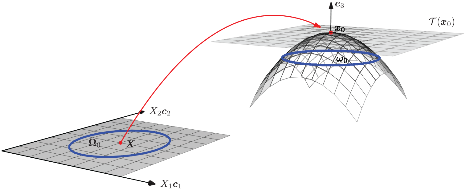
Schematic representation of the geometric deformation of a planar mid-surface.
In what follows

where we have denoted by
Let

2.2. Large rotations and small deformations of the designed shell
Let

We shall also assume that

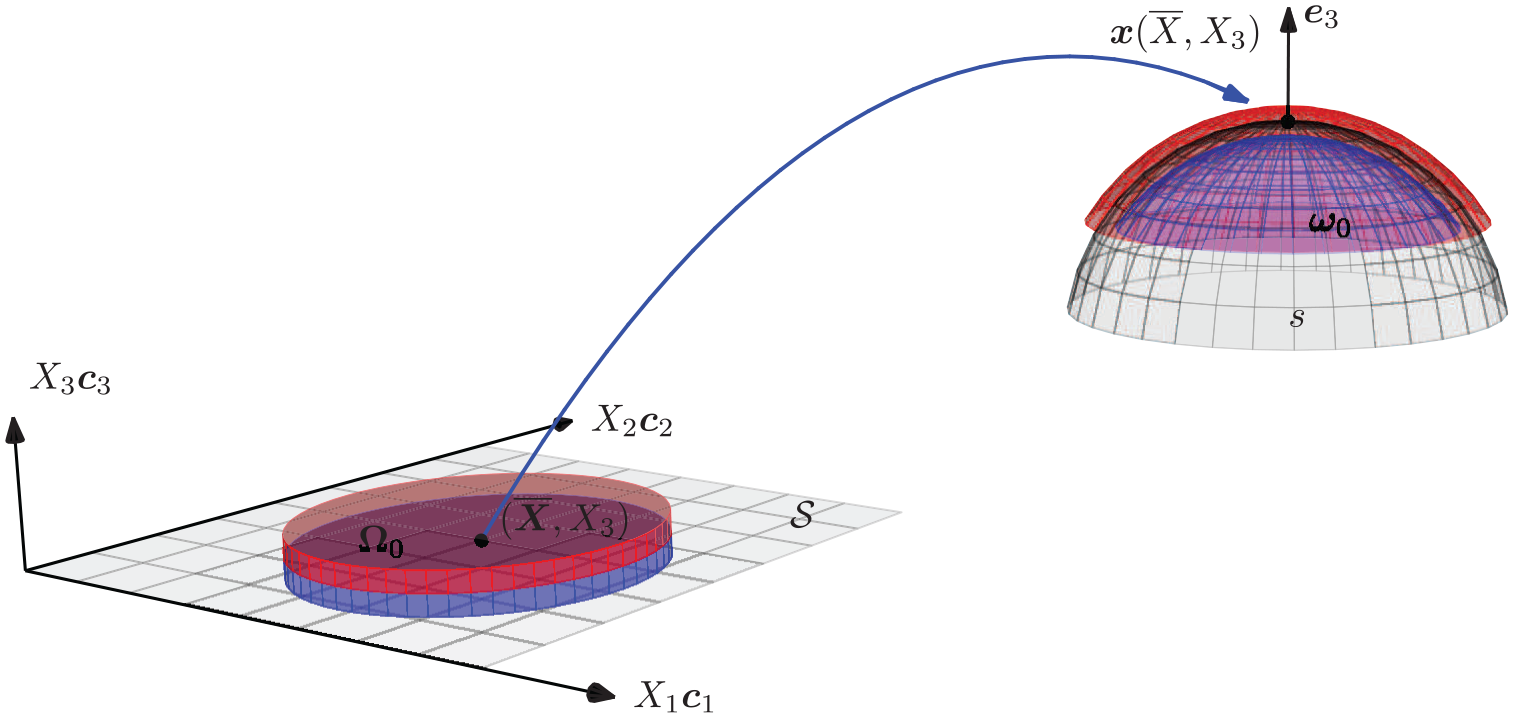
Schematic representation of the deformation of a plate.
Restricting attention to orthotropic materials, which are a subclass of materials exhibiting reflection symmetry with respect to the mid-surface considered by Steigman [26], we consider the expansion of the 3D transformation with respect to the thickness as

where

2.3. Small perturbations of the designed shell
To define a small perturbation of the previous kinematics we consider the following.
An in-plane displacement

An out-of-plane displacement

The plate perturbation, defined as

involves a kinematics of Love–Kirchhoff type. However, we have to point out that the out-of-plane displacement w does not have the same scaling as in the Love–Kirchhoff theory. This was necessary because the mid-surface of the shell has to be close to the designed surface
The plate-to-shell kinematics considered in this article superpose the exact design kinematics

In conclusion, the designed surface
The following result estimates the distance between the mid-surface of the shell


where
Proof. As
2.4. First-order deformations
The deformation gradient tensor


Having in mind the asymptotic assumptions (2.3)–(2.5), the deformation gradient tensor

where

Finally, using assumption (2.1) we obtain the (finite) strain tensor

where
3. Plate-to-shell equations for design
In this section, we introduce the plate-to-shell equations for orthotropic materials. The principal unknowns of the problem are the small perturbation
3.1. Constitutive assumptions
We consider here a pre-stressed hyper-elastic material. For small deformations

where
In what follows, we consider only orthotropic materials with the elastic coefficients

where

where
Concerning the pre-stress

where
From (2.13) and the assumption (3.3) the constitutive equation (3.1) reads

where the in-plane stress

Let

3.2. Boundary conditions
In order to formulate the boundary conditions let us denote by
It follows that the stress-free boundary condition on the lateral boundary can be written as

On the upper and lower boundaries

From the normal components

The solution of the above linear system will be denoted by
3.3. Plate-to-shell equations
We consider here the plate-to-shell equations for design associated with the kinematics introduced in Section 2. These equations, deduced in the Appendix using a classical asymptotic expansion method, involve the in-plane stress resultants and couples. If

then, from the tangential components (in the deformed configuration) of the equilibrium equations (see the Appendix), we obtain

while the normal component (in the deformed configuration) of the equilibrium becomes

If we introduce the in-plane stress couples

then, the tangential components (in the deformed configuration) of the equilibrium equations read

while the normal one becomes

To summarize, we have derived six linear equations (three for the resultants (3.9)–(3.10) and three for the couples (3.11)–(3.12)) for the three small-perturbation unknown functions
3.4. Weak transversal heterogeneity
We assume further that the material has a weak transversal heterogeneity, that is,


In this case the system (3.8) has a simpler form and we obtain

If

denotes the pre-stress resultants then, the in-plane stress resultant is

The average shell equations (3.9)–(3.10) become a linear partial differential equation for


while the normal component (in the deformed configuration) gives

Let

Then the stress couple


We end this section with several remarks.
We note that the small perturbation

and the compatibility conditions to be satisfied for the right-hand side of (3.19) are sufficient conditions for the existence of a solution
We also note that w can be computed explicitly from (3.16) and we have only two (degenerate) equations for

where we have denoted by

By solving (3.17)–(3.18) we obtain the three components of the unknown pre-stress couple

which means that
For isotropic materials the condition of weak transversal heterogeneity (3.13) becomes

the elastic in-plane stress tensor

and we can see that (3.14)–(3.15) and (3.17)–(3.18) are membrane-type equations.
4. Applications to some classical designed surfaces
In this section, we apply the plate-to-shell equations for design, introduced in the previous section, to three classical surfaces: a sphere, a cylinder, and a cone. In this section, we consider only isotropic materials with a weak heterogeneity, that is, (3.2) and (3.22) hold.
Special attention will be paid for the plane pre-stress configuration induced by a small pre-strain

and the pre-stress resultant and pre-stress couple are
A particular case of a plane pre-stress configuration induced by a small isotropic pre-strain pre-strained elastic layer is the following two layers system. One layer of thickness h1 is grown under stress-free conditions on an elastic layer of thickness h2, that is,

4.1. Small parts of spherical surfaces
Let

then after some algebra we have

The unit normal of the Eulerian surface is

Let us show that if

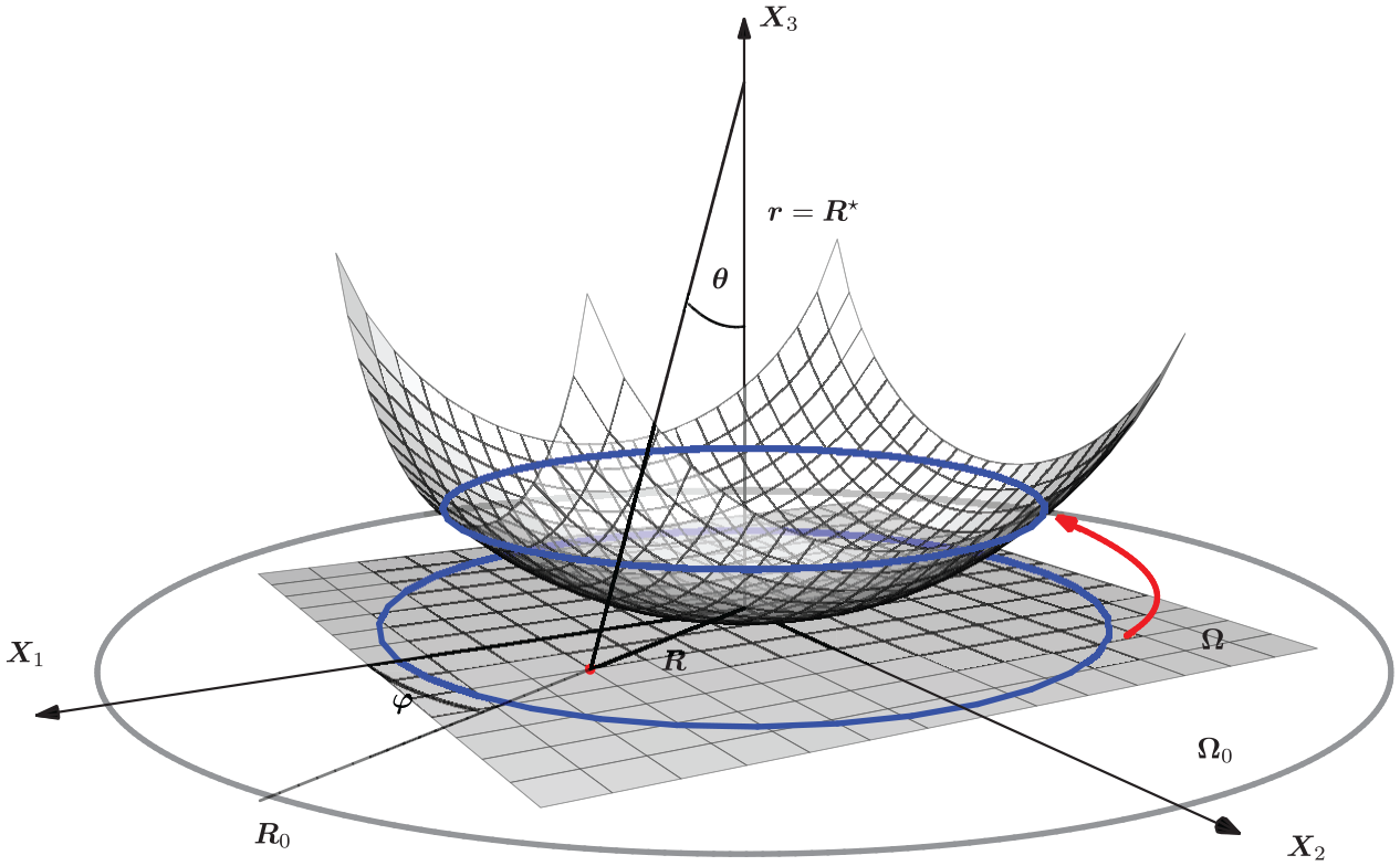
Illustration of the radial projection
We can now compute

If

We note that the small perturbation

and if we suppose that

while the boundary conditions read

Finally, from (4.5)–(4.7) we found the pre-stress couples
For isotropic pre-stress/strain given by (4.1) equations (4.5)–(4.7) reads

and the equilibrium equations for the moments are satisfied for all the geometries
In conclusion, we found that: a spherical configuration of radius
In the particular case when an isotropically pre-strained elastic layer of thickness h1 is grown under stress-free conditions on an elastic layer of thickness h2, that is,

where we introduced
A refinement of this result may be obtained from (4.8) using

which, obviously, reduces to (4.9) when
The comparison between the theoretical, numerical, and experimental results is illustrated in Figure 4. Let us describe first the experimental results. We have grown a bi-layer semiconductor material that consist of a
Right, top: Experimental evidence of a
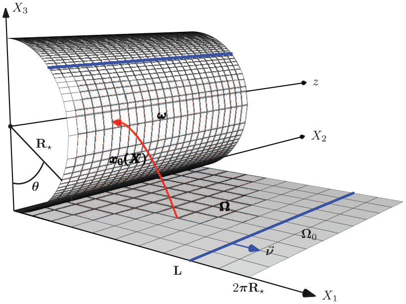
Illustration of the cylindrical projection
If we suppose that the elastic coefficients are homogeneous, then the radius
The 3D finite-element numerical computations of the relaxation of the same finite elastic square (
4.2. Cylindrical surfaces
We use

then, after some algebra, we obtain

Obviously, the unit normal of the Eulerian surface is

Let

and (2.1) follows with
Once again, the small perturbation

If we assume further that

Finally, from (4.13) and (4.14) we found the pre-stress couples
For isotropic pre-stress/strain given by (4.1) the first alternative in (4.14) cannot be true and (4.13) reads

In conclusion, a cylindrical configuration of radius
Let us analyze here the case of a bi-layer material that is isotropically pre-strained/stressed in the upper part (i.e., (4.2) holds). If it has equal elastic coefficients, from (4.15) we find the cylinder curvature

where, as previously,
which again reduces to (4.16) when
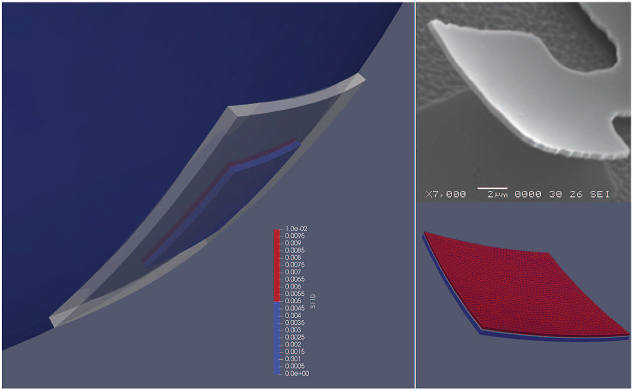
As in the previous subsection, we present here a comparison between the theoretical, numerical, and experimental results. Figure 6(right) shows a scanning electron microscopy (SEM) image of an experimental realization of a cylindrical shape starting from a pre-strained bi-layered material. It concerns a 50
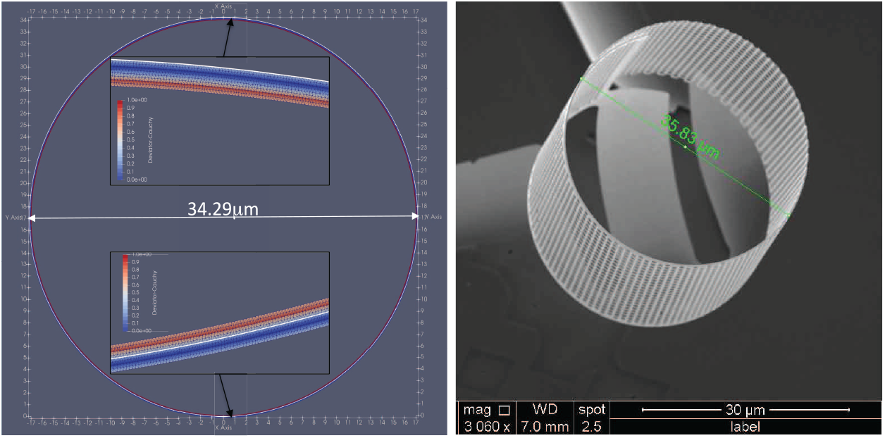
Right: Experimental evidence of a large surface with vertically non-homogeneous but isotropic in-plane pre-strain whose relaxed shape is a cylinder and the experimental value of the diameter. Left: The designed cylinder computed with formula (4.16) versus 2D finite-element computations of the relaxation of an elastic plate with a pre-strain/stress. Zoom on the upper and bottom part.
The diameter of the designed cylinder, predicted by the simplified formula (4.16), is
The 2D finite-element numerical computations of the relaxation of the plate with a pre-strain given by (4.2) versus the designed cylinder, predicted by the simplified formula (4.16) is shown in Figure 6(left). The error between the numerical diameter
4.3. Conical surfaces
Let us consider the spherical coordinates

and a straightforward computation gives

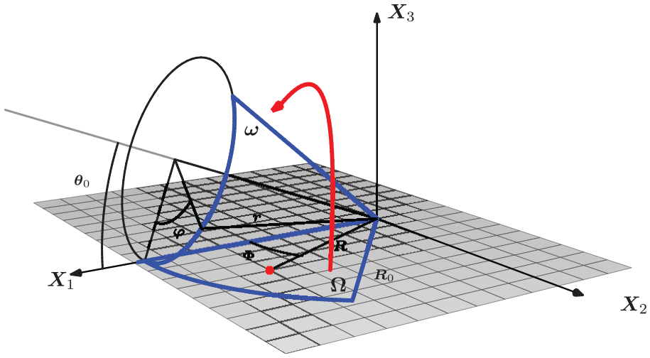
Illustration of the map (4.18).
The unit normal of the Eulerian surface is

Let

Then (2.1) follows with

As previously, the small perturbation

For materials with a circular symmetry (i.e.,

Finally, from (4.21) and (4.22) we obtain the pre-stress couples
For isotropic pre-stress/strain given by (4.1) the necessary conditions (4.21) and (4.22) are

Finally, we conclude that a conical configuration of angle
Since, for technological reasons, an experimental realization of a cone relaxation is not yet possible, we restrict ourselves to a comparison between theoretical and numerical results. Let us describe first the mechanical settings. The plate is a pre-stressed bi-layered homogeneous material of constant thickness

where

The Lagrangian plate is a the angular sector
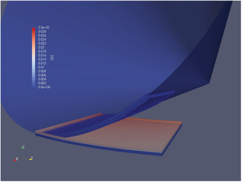
The designed cone of angle
5. Conclusions
We have investigated the interplay between mechanics and geometry in the case of a pre-strained/stressed ultra-thin film. Our aim was to construct a theoretical framework able to enlarge the class of 3D objects that can be fabricated from suitable planar design by using relaxation of pre-strains/stress. Toward the applications in the field of light-engineering (photonics), we have focused on semiconductor materials only, which are brittle–elastic materials. For this practical reason the mechanical relaxation problem has to deal with the small deformations only. This is actually a technological restriction and not a mathematical simplification of the problem. As is the case of buckling, large rotations are mandatory in order to describe the complex 3D relaxed shapes of various planar geometries. The design problem considered in this article can be formulated as follows: given a shape of a shell’s mid-surface (described as a 3D image of a plate mid-surface) find some sufficient conditions on the shell’s thickness, on the pre-strain/stress and on the shape of the plate mid-surface such that the pre-strained/stressed plate could relax with small deformations into the given shell without any other loading effort.
As the above design problem is very complex we will split it into two simpler problems. The first, called the geometric design problem, consists of finding a small strain transformation of planar surface into a 3D surface. Significant effort was done (see, for instance, [33–36]) on isometric transformations (no strain deformation), which represent a special class of small-strain transformations (2.1) considered here. We do not give here any general mathematical treatment of the problem, but we take it like a geometrical input. Moreover, we provide three classical geometries examples, the small-diameter spherical surfaces, the (arbitrary) cylindrical surface, and the conical surfaces, but as expected, many others could also be considered. While the last ones are isometric transformation, the first one is not.
The second design problem, called the mechanical design problem, is related to the relaxation of a plate with a non-homogeneous (in thickness) pre-strain/stress. The deformation of the mid-surface is supposed to be known (see the first geometric problem) and characterized through the small deformation tensor and the curvature tensor. Over this geometric design problem (which reproduces exactly the target mid-surface) we consider a small perturbation of Love–Kirchhoff type in order to compensate for the small (membrane) deformation of the proposed geometric transformation. As a consequence, the mid-surface is close to the designed geometric mid-surface, and we deal with an approximative design problem. The resulting six equations for efforts’ average and moments for three unknowns (two in-plane and one out-of-plane displacements) will provide three supplementary equations to compute the in-plane pre-strain/stress moments.
A special attention was devoted to orthotropic materials with weakly transversal heterogeneity and with an isotropic pre-strain. From a practical perspective, these materials can be obtained by modern methods for crystal growth (MBE) where the pre-strain/pre-stress can be controlled by the composition and the heterogeneity is purely vertical as a consequence of the layer-by-layer growth mode. In this case, the system of equations is simplified and the efforts–moments system involves only the pre-strain moments and the thickness. In the special case of isotropic materials the three examples considered here (sphere, cylinder, and cone) can be easily handled to obtain the formula of the pre-strain moments as a function of the curvature radius and the thickness.
For a given isotropic pre-stress/strain, we have found that a rectangular plate could relax both into a cylindrical surface (if the boundary is parallel to cylinder axis) or on a part of a sphere in which case it should have a small diameter with respect to the sphere radius. In both cases, the theoretical estimates have been compared with the experimental realizations and finite-element numerical computations and we found very good agreement between all of them. For the cone geometry, we found that the design is not possible from an isotropic pre-stress with an in-plane homogeneity. For a non-isotropic pre-stress, given from the theoretical expressions, the 3D finite-element computation of the relaxed surface matches very well with the designed conical surface.
Footnotes
Appendix: Deduction of the plate-to-shell equations
In this appendix, we use a classical asymptotic expansion method to deduce the plate-to-shell equations for design (3.9)–(3.12) associated with the kinematics introduced in Section 2.
The equilibrium equation in the absence of the body forces reads
Acknowledgements
We are grateful to Ph. Regreny, P. Cremillieu, and J.-L. Leclercq for the fabrication of pre-strained thin multi-layered films and associated clean-room technology at the NANO-Lyon fabrication facility at the Institute of Nanotechnologies in Lyon.
Funding
The author(s) disclosed receipt of the following financial support for the research, authorship, and/or publication of this article: This work was partially supported the French Research Agency (Grant Number ANR-17-CE24-0027) and the Romanian National Authority for Scientific Research and Innovation, CNCS-UEFISCDI (Project Number PN-III-P2-2.1-PED-2016-0436), within PNCDI III.