






Abstract
This article aims to study the modeling and simulation of Ti6Al4V micro-lattice structures under the same compressive loads. Initially, five distinct unit cell topologies (Grid, X, Star, Cross, and Tesseract) were used to design lattice structures. For the modeling of these lattice structures, both three-dimensional wireframe and solid (homogeneous and heterogeneous gradient) meshing were employed. However, the geometric design parameters, such as strut length, strut diameter, and, in particular its configuration (5 × 5 × 5 array), have been assessed as the same for all types of lattice structures. Here, the finite element (FE) modeling approach is used to evaluate the elastic and elasto-plastic behaviors of these structures due to subjected uniaxial compressive loading. The FE results have been validated in previously reported experimental data and have been well comprehended. The static linear and nonlinear FE method formulations are based on the Timoshenko beam theory and Johnson–Cook damaged model, which describe the elasto-plastic behavior. The FE simulations results (linear and nonlinear) were studied and it was shown that Star lattice structure has high stiffness value at low porosity, compared to the other lattice structures. Hence, to further determine the optimum variables (strut diameter –Sd and pore size –PS) for the Star unit cell-based lattice structures, the Taguchi-based optimization technique with L9 orthogonal array was used. In addition, a linear regression model was developed to estimate the maximum initial yield stress for the optimum variables. Finally, the same configuration of Star lattice structures was designed by the heterogeneous solid gradient mesh approach with two swapping conditions, ‘A’ and ‘B.’ These models were employed to perform linear static FE simulations. Therefore, the swapping condition and the type of gradient-based lattice structures, possessing high and low compressive stresses, were identified.
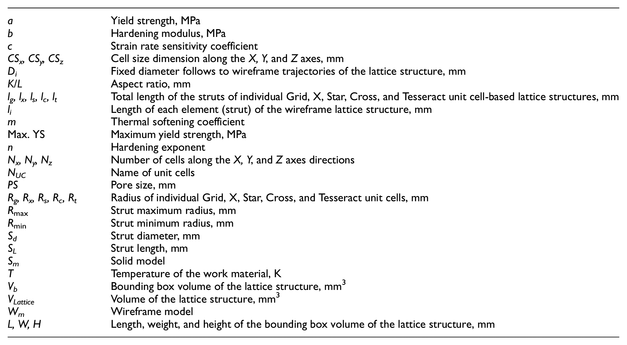
Nomenclature
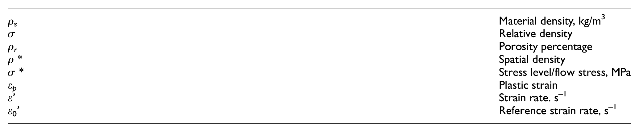
Greek symbols
1. Introduction
Since human beings first noticed the anisotropic behavior of natural material structures (wood, coral, pearl, and cancellous bone), they have been inspired and learned how it could be fabricated in the form of cellular structures. Hence, artificial techniques with synthetic materials, such as metals, polymers, and ceramics, have been designed to fabricate structures mimicking natural materials [1–4]. Recent studies have revealed that the micro-lattice-based architecture exhibits ultra-stiff and ultra-light mechanical metamaterial at ultra-low density. This performance is acquired from the arrangement of microscale unit cells with its node connectivity and nanoscale features. Usually, these lattice architectures are designed to carry loads in tension or compression [5–8].
To design the mechanical metamaterials by using a multi-disciplinary approach, a synergistic relationship between the different phases from design to manufacture and validation methodologies were developed. These methodologies involve also experimental techniques and modeling approaches that help to design new metamaterial multiscale architectures. Thus, fabrication can be effectively guided by a precise theoretical and experimental framework [9]. Similarly, the mechanical behavior of designed micro-metric pantographic metamaterials was also investigated and different mathematical models (discrete or continuous) were developed [10,11]. Hence, it is a broad research area, especially for engineering and biomedical applications.
In the past two decades, many researchers have investigated how to calculate the mechanical properties of lightweight cellular structural materials fabricated by additive manufacturing (AM) techniques [12–14]. Lightweight titanium alloy (Ti6Al4V) cellular structures have gained significant popularity due to their superior mechanical responses, corrosion resistance, and biocompatibility properties [15]. Their density (ρs) is only 4432 kg/m3 compared to 7900 kg/m3 for 316 stainless steel and 8300 kg/m3 for cast CoCrMo alloys [16].
AM can improve the potential ambient performance of a metallic lattice structure, such as low weight and high energy absorption, and obtain the desired mechanical properties used in various engineering fields. In addition, it provides superior thermal and acoustic insulation properties. Laser additive manufacturing (LAM) is an innovative approach (layer by layer) to fabricate simple or complex product designs [17]. This emerging technique offers geometric freedom with great potential to build lightweight lattice structures, which are highly desired for engineering applications [18]. To easily alter the design of the structure at any place, the modifications should be incorporated in the three-dimensional computer-aided design (3D-CAD) model [19–23]. For example, the AM built titanium alloy (Ti6Al4V) lattice structures are well suited due to their outstanding mechanical and biological properties [24,25]. In contrast, conventional manufacturing processes possess limited design capabilities to build lattice structures. The geometrical design variables of a lattice topology largely affect the mechanical response, which also depends on the materials and fabrication process [26].
Cellular solid materials [foam (open or closed), lattice, truss, and honeycomb] structures can deform by either the bending or stretching of the cell wall or cell network (ligament). However, most cellular structures are bending-dominating, while those that are stretching-dominating have considerably more weight reduction for structural applications. At the same relative density, the Young’s modulus and yield strength of stretching-dominating cellular structures are considerably higher compared to those of bending-dominating cellular structures [27]. Despite the fact that the stochastic open foam structure has an advantage over the periodic (heterogeneous and homogeneous) lattice structure because it has soft and high energy-absorbing characteristics, open foam structures are much more challenging to tailor from the viewpoint of pore network distribution [28].
Based on the designer’s requirements, the lattice structure can be fabricated as custom-made, whereby the required mechanical properties for specific applications can be achieved. The morphology and volume fraction of the lattice are subjected to adjustments to reach the desired properties [29]. The feature advantage offered by cellular solid materials is high strength accompanied by a relatively low mass. The nature of the internal voids classifying cellular lightweight structural materials – either stochastic or ordered – is shown in Table 1.
Classification of lightweight structures.

Initially, Sypeck [30] focused on the fabrication and performance of lightweight materials structures (e.g., cellular solids, composites, etc.). He provided a comprehensive review regarding metal cellular solid structures and their different fabrication techniques. In addition, the work presented in ‘Metal foams: a design guide’ [31] offers an important understanding of the manufacturing, utility, and properties of these structures. This design guide also demonstrated how foam-based structures should be employed, under the scope of cost, material, and fabrication methods, for a wide range of applications.
Deshpande et al. [32] investigated the effective mechanical properties of the lightweight octet-lattice structure (aluminum alloy) material by both experimental and theoretic approaches. The fabricated structures were built through the lost-wax investment casting process. However, the strength and stiffness of the octet-lattice material are provided due to its stretching-dominating nature, which is associated with the node connectivity inside the lattice structure. Thus, the authors observed a close match between the analytical and the finite element (FE) calculated results, such as strength and stiffness, which were compared with experimental test data. The conventional foam strength and stiffness scales are ‘σ3/2’ and ‘σ2,’ respectively, which was demonstrated by Deshpande et al. [27], whereas ‘σ’ represents the relative density. In such structures, a bending mode of deformation commences due to the applied load.
Hollander et al. [33] investigated the structural, mechanical, and in vitro characterization of Ti6AL4V porous specimens fabricated by the direct laser forming (DLF) technique. By performing tensile and bending tests for both untreated and annealing treated specimens, they compared the resulting yield strength and fatigue properties, respectively. In addition, their characterizations (i.e., morphology vitality, proliferation, and cell diversity) were obtained for non-porous and porous blasted DLF specimens using scanning electron microscopy (SEM). It was suggested the DLF Ti6AL4V specimens fulfill potential mechanical properties and further could fulfill potential mechanical properties that could be used in the field of hard tissue biomaterials.
Cheng et al. [34] investigated the mechanical properties of two different Ti6Al4V cellular solids, (a) open foam and (b) lattice-based structures, which were fabricated using the electron beam melting (EBM) technique. It was shown that the modulus and compressive strength properties of the open foam materials with dimensional parameters (25 × 25 × 40) mm are 0.19–0.49 GPa and 3.8–4.5 MPa, respectively, at a porosity range of 91.65–90.08%. Similarly, lattice-based structures with bounding box dimensions (15 × 15 × 30) are 0.54–6.34 GPa and 12.4–112.8 MPa at a porosity range of 86–62%. The authors concluded that during axial compressive deformation the lattice structures have higher specific strength than the stochastic foams. They also compared these structures with the mechanical properties of human bone (trabecular and cortical bone) structure properties.
Gibson and Ashby [1] developed an analytical model to investigate the compressive responses on titanium body-centered cubic (BCC) micro-lattice material. The response of the analytical model was compared to the corresponding experimental results. Besides, the preliminary studies on analytical and FE models were successfully employed for the investigations of sandwich textile core and truss core material-based structures under different loading conditions [35,36]. Labeas and Sunaric [37] demonstrated a methodology to analyze the compressive quasi-static and failure responses of three different sandwich core (i.e., BCC, BCC-Z, and F2FCC-Z) architectures. Simulations were performed using ANSYS, and were based on linear and nonlinear (elasto-plastic) approaches consisting of the Timoshenko beam element model. The models aimed to provide a good correlation between the FE analysis and the experimental results. The selective laser melting (SLM) technique was used to build the lattice structures, and variation on the strut radii in fabricated structures was observed due to inhomogeneities and material concentration on the strut intersection points. They suggested that the strut aspect ratio, the unit cell (types, size and shape), and spatial configuration (n×n×n) arrangements are the geometrical design variables of lattice-based architectures, which highly influence the mechanical responses. Lastly, it was concluded that the plateau stress of the lattice structure can be accurately estimated using the FE model. It needs to import the material plastic properties and increase the number of unit cell configurations with a decrease in the unit cell size.
In the recent literature, specifically for biomedical engineering, there are various experimental and numerical studies on the failure and morphological analysis of lattice structures materials. For example, the morphological features in terms of in vivo and in vitro biocompatibility, along with the mechanical properties of metallic porous scaffolds, have been addressed [24,38–40]. Previously, the analytical model and Timoshenko beam or Bernoulli–Euler approaches were used to predict the mechanical behavior of several single-unit cells (cubic, tetrakaidecahedral, diamond, and octahedral) [41–44]. Similarly, Ahmadi et al. [45] derived analytical solutions to investigate the mechanical properties of the Ti6Al4V diamond lattice structure. A good correlation between the analytical and numerical solutions (using Timoshenko beam theory) was presented for the mechanical properties with small density, which were also compared by experimental results. However, for a large density structure, the mechanical properties were predicted by analytical solutions based on Bernoulli–Euler beam theory deviating from the experimental results. The FE model prediction results are less accurate compared to the experimental results.
Smith et al. [46] developed FE models to predict the quasi-static compressive response and collapse behavior for two different lattice-based structures, namely BBC and BBC-Z, at varying densities. The lattice structures were built using stainless steel material through the SLM technique. The two FE models (i.e., beam and 3D brick elements) were used for the prediction of mechanical properties and were compared with the experimental quasi-static compression results on lattice structures. ABAQUS software was employed to perform the FE simulation. The authors highlighted the key difficulties in the modeling of the SLM lattice structures and also offered a possible solution. They also presented an analytical model for BCC unit cells, which have a fixed length (L), but the width (K) reduces in terms of aspect ratio (K/L) (i.e., 1, 0.9, 0.8, etc.). This model was used to calculate the initial stiffness and plastic collapse strength, and has been validated well with the FE beam model and experimental results. In this literature, it was suggested to improve the mechanical properties in the lattice structures by reducing the unit cell aspect ratio.
Terriault and Brailovski [47] presented an approach to quickly design lattice structures with a large number of struts, which can be easily arranged as a form of functionally graded porosity structure. They have shown that the FE meshers can generate small mesh volume tessellations into a series form, which filled easily on a complex solid 3D-CAD geometry. The edges of the tetrahedrons were defined as the strut section. The use of numerically and experimentally techniques indicated two significances: (a) FE simulation results with beam elements could predict displacement and stiffness of the structure and (b) the experimental technique highlights two main technical challenges, namely non-uniform material properties and non-conforming geometry.
An extensive experimental and analytical literature study is available for compressive behavior on the Ti6Al4V lattice structure for many distinct engineering applications. The characterization of various types of lattice structures of different materials by conducting experimental studies is very expensive and time-consuming. The FE simulation studies are beneficial because (a) it is easy to calculate and attain the stress distribution in the structure (b) and they reduce the time and cost for achieving detailed responses of the object with defined loading and boundary conditions. The motivation of this paper arises in one previously published research work presented by Smith et al. [46].
In this study, the five different unit cell-based Ti6Al4V lattice structures were created using CAD software. These are Grids (G), X (X), Star (S), Cross (C), and Tesseract (T). The unit cell was arranged into a 5 × 5 × 5 array in the lattice structures. The same arrangement (5 × 5 × 5) was used by Kadkhodapour et al. [48]. They reported that the reason for selecting this arrangement is due to prevent high central processing unit (CPU) times for solving the FE model. Both 3D wireframe and solid CAD geometries have been used for further FE simulations. These periodic lattice structures were constructed by simply repeated unit cell geometries. Preliminary, for the modeling of all five lattice structures, the unit cell geometry size and strut diameter have been kept the same.
Before proceeding to analyze the structural responses in this study, a numerical validation was performed using both beam and 3D tetra elements of Ti6AL4V lattice structures with an already published experimental work, presented by Merkt et al. [49]. Static linear and nonlinear FE analysis has been employed to predict the mechanical responses within the lattice structures under uniaxial compressive loads. The results of the compressive properties were compared to identify which structural performance is higher. Furthermore, the optimized (high-performance) structure was modified in terms of two design variables, namely the strut diameter (Sd) and pore size (PS), at three different levels. The optimized structure is implemented via the Taguchi method to identify the optimal design variables for high yield stress and low compressive stress. The aim of this study is to accurately develop FE models for given lattice structures under compressive loads. It is reported how the mechanical properties are influenced due to varying Sd and PS of the unit cell of the lattice structures. The main intention of this work is to predict the stiffness and yield strength of such unit cell-based structures. This FE model approach could help in assessing the structural responses with arbitrary geometry of the lattice structure under compressive loads. Consequently, this methodology could help to improve the mechanical properties of AM fabricated Ti6AL4V micro-lattice-based implants or scaffolds. Hence, a design engineer can easily modify them to fill the desired mechanical properties of the unit cell-based lattice structures.
2. Design methodology
2.1 Unit cell architecture
Tang et al. [50] presented a design methodology of unit cells on the basis of relative node position and topology. The authors consider the topology of a unit cell is within tri-dimensional bounding box, and this bounding box center represents the origin of the local coordinate system. It was suggested that (a) the unit cell pattern must be symmetric with respect to three local coordinate planes and also (b) its orientation is particularly essential; further, these allow the designer to improve the mechanical performance of the lattice structure. In addition, it shows a graphical model to represent a unit cell. In this proposed design methodology, a typical unit cell topology is used to create micro-lattice structures, simply repeating unit cells in three principal directions X, Y, and Z, respectively. In this unit cell topology, a geometry variation in the three principal directions can be easily managed. Five different unit cell topologies were selected, namely G, X, S, C, and T (see Figure 1). The outer geometry of G, S, and T are similar to that of the cubic type, but internally, it is changed. Concurrently, X and C unit cell topologies are different from each other. The ordered arrangement of each unit cell is in terms of (element) strut and (node) vertex numbers, which have defined according to the crystal structure of an atom. The total number of nodes and elements of the five unit cells are represented in Table 2, where NUC represents the name of the unit cells.
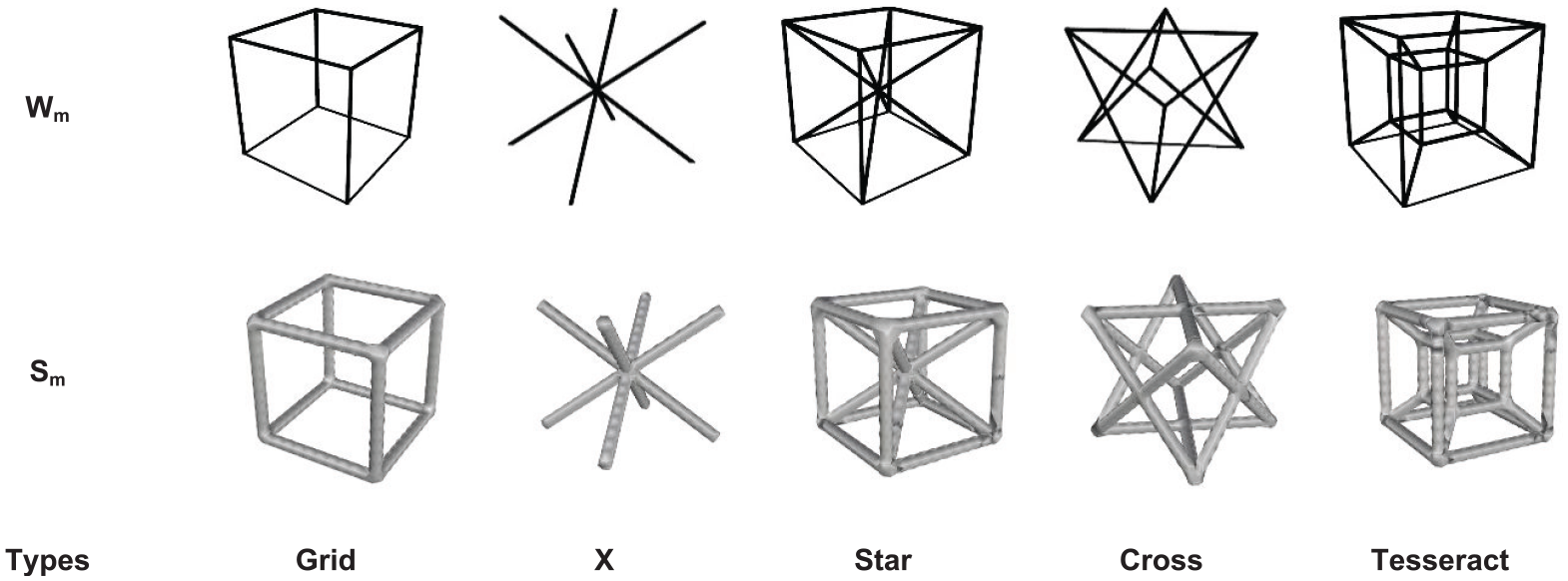
Wireframe (Wm) and solid (Sm) models of five typical unit cell architectures.
Number of nodes and elements in wireframe unit cell architecture.

2.2 CAD lattice structures modeling
This section illustrates the building of the wireframe and solid CAD lattice structures model by using open source (INTRALATTICE) CAD software. This software is developed by McGill’s Additive Design and Manufacturing Laboratory (ADML, 2013) [51], based on Grasshopper, a graphical algorithm editor for Rhinoceros 3D software. It has a number of CAD tools to generate both (wireframe –Wm and solid –Sm) lattice structures within the design space with defined preset or custom cell topology. The benefits of this for design are lightweight structural integrity, porosity in bone scaffolds or implants, and topology optimization.
In this present article, two solid CAD modeling methodologies have been used, called the periodic homogeneous (constant radius) (Section 2.2.1) and heterogeneous gradients (gradient strut radius) (Section 2.2.2). Initially, both modeling techniques required a frame module (generate wireframe geometry), which was connected to preset or custom cell topology. The frame module contains the cell size (CSx, CSy, CSz) and number of cells (Nx, Ny, Nz) to generate a line/wireframe lattice structure model. Subsequently, this frame module is added to the mesh module, whereby it can be converted into either one of the two valid solid mesh geometries (homogeneous mesh and heterogeneous gradient mesh).
2.2.1 Homogeneous mesh
The construction of homogeneous mesh over wireframe lattice geometry needs struts (lists of curves) and the radius as the input data. For example, a preset cell (Star) topology is connected to an optional basic box frame module, which consists of the cell size (CSx, CSy, CSz) and the number of cells (Nx, Ny, Nz) with respect to the global coordinate system, as illustrated in Figure 2. The above steps are well described in constructing 3D wireframe models. In addition, for modeling the solid lattice structure, a given 3D wireframe geometry is paired with the homogeneous mesh module, herein needing to be defined only as a single parameter (radius), which represents the circular cross-section of the strut. Further, it can be created and saved in standard CAD file format (i.e., 3dm, STL, PLY, OBJ, etc.). The mesh report and mesh preview consists of the utility module, and it represents the mesh details and geometrical views.
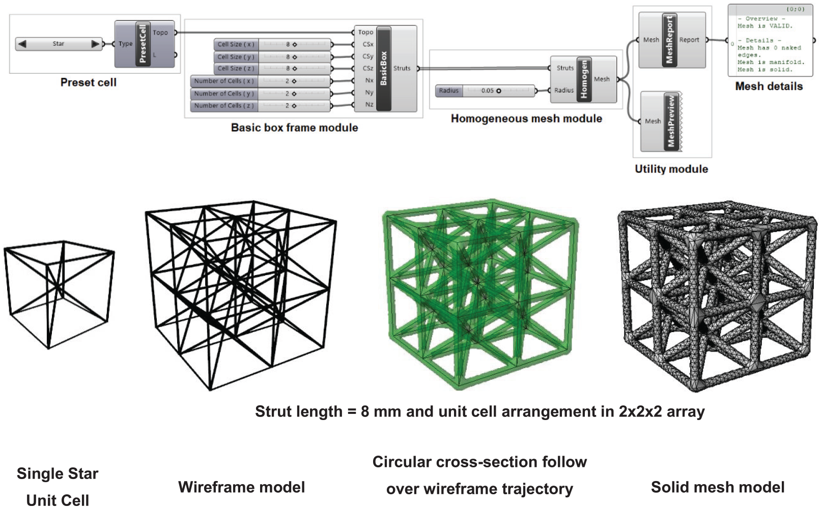
Homogeneous solid mesh modeling of lattice structures.
2.2.2 Heterogeneous gradient mesh
In the construction of heterogeneous gradient mesh, the basic box frame module (wireframe geometry) is similar to that used in the homogeneous mesh construction module. The given 3D wireframe geometry is connected with the heterogeneous gradient mesh module that herein needs to be defined with preset gradient types, maximum radius (Rmax) and minimum radius (Rmin), which represent the circular cross-section of the struts followed by the gradient functions. Subsequently, it is created and saved, which was explained in Section 2.2.1. For example, a Star unit cell is used for constructing heterogeneous solid mesh. Figure 3 shows the generation of the heterogeneous mesh module.
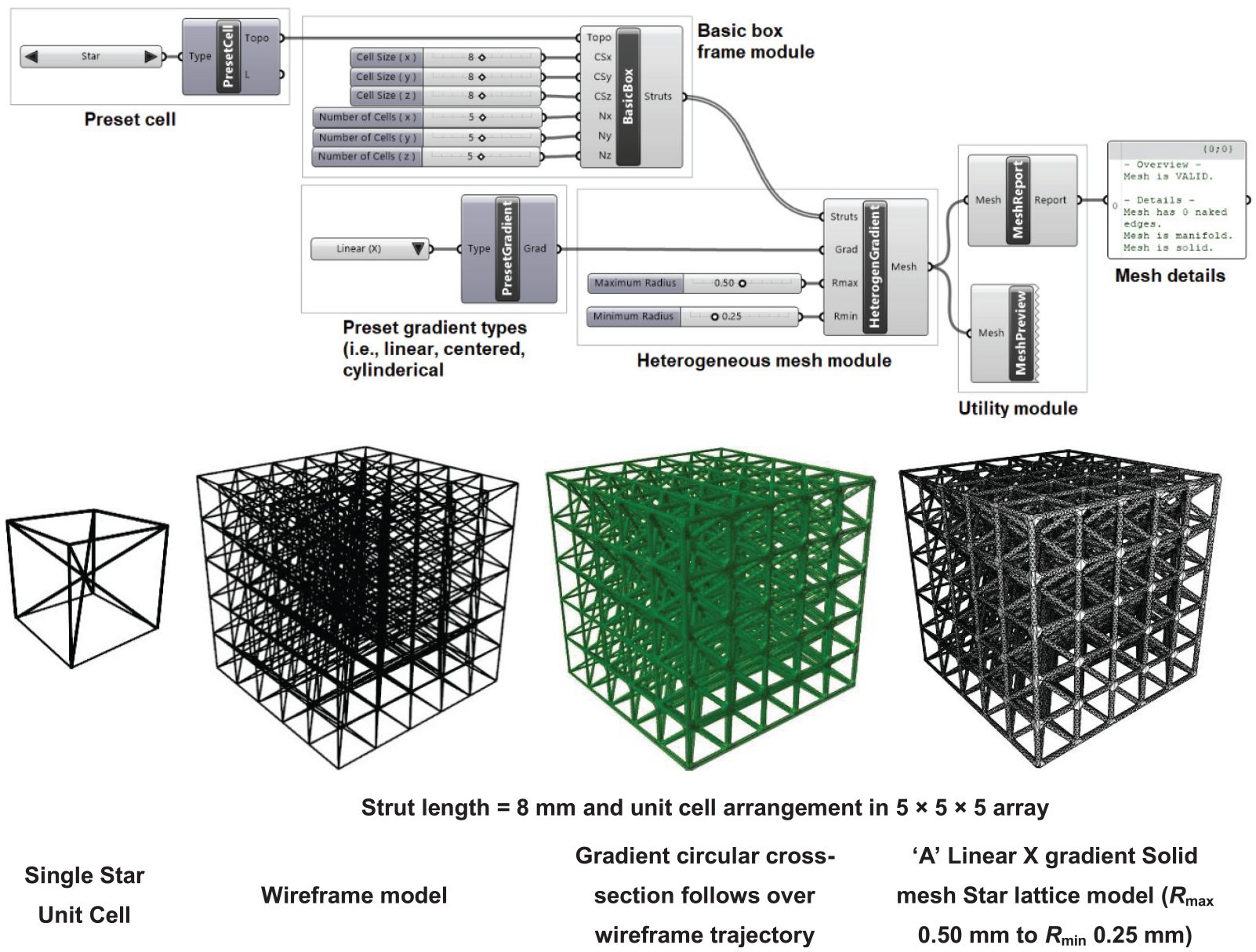
Heterogeneous solid mesh modeling of lattice structures.
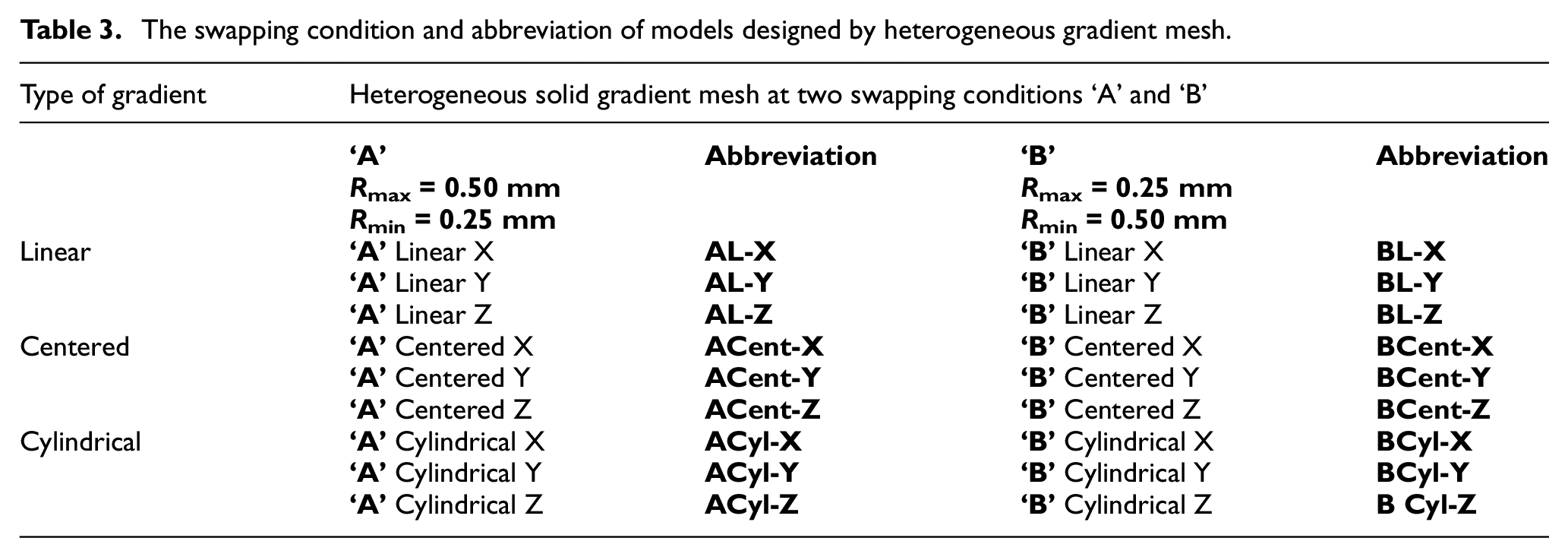
In addition, we can also reverse the gradient by just swapping Rmin and Rmax of the mesh geometry or developed our own gradient function. The ‘A’ linear Z-axis (Rmax 0.5, Rmin 0.25) illustrates the type of preset gradient that is connected with the heterogeneous mesh module at Rmax– 0.5 and Rmin– 0.25. Meanwhile, in the ‘B’ linear Z-axis (Rmax 0.25, Rmin 0.5) the gradient is reversed by swapping Rmax– 0.25 and Rmin– 0.5 (shown in Figure 4). The term ‘A’ represents without swapping, and the term ‘B’ shows with swapping the Rmax and Rmin values. There are a total of nine preset gradients, in which the main three types of gradients (i.e., linear, centered, and cylindrical) and each type have three mathematical functions g(x,y,z) with a unitized domain in all three X, Y, and Z axes, as represented in Table 3.
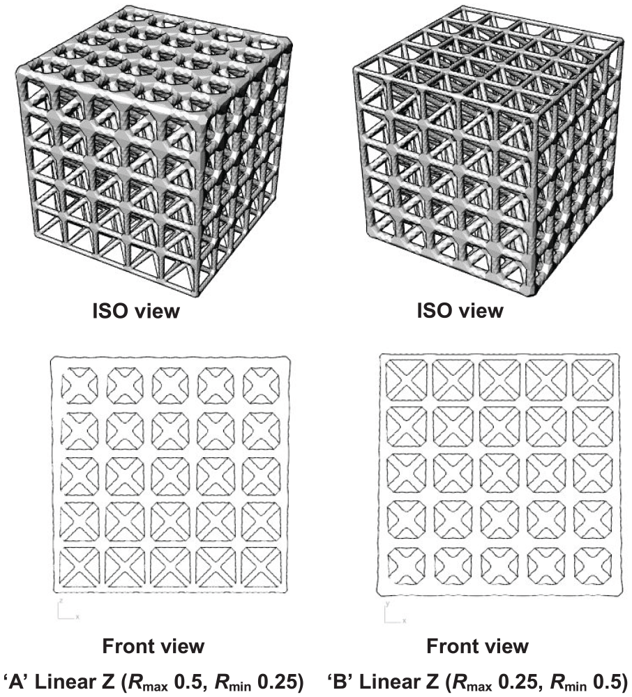
Heterogeneous solid mesh modeling of Star lattice structures without and with swapping Rmax and Rmin.
The swapping condition and abbreviation of models designed by heterogeneous gradient mesh.
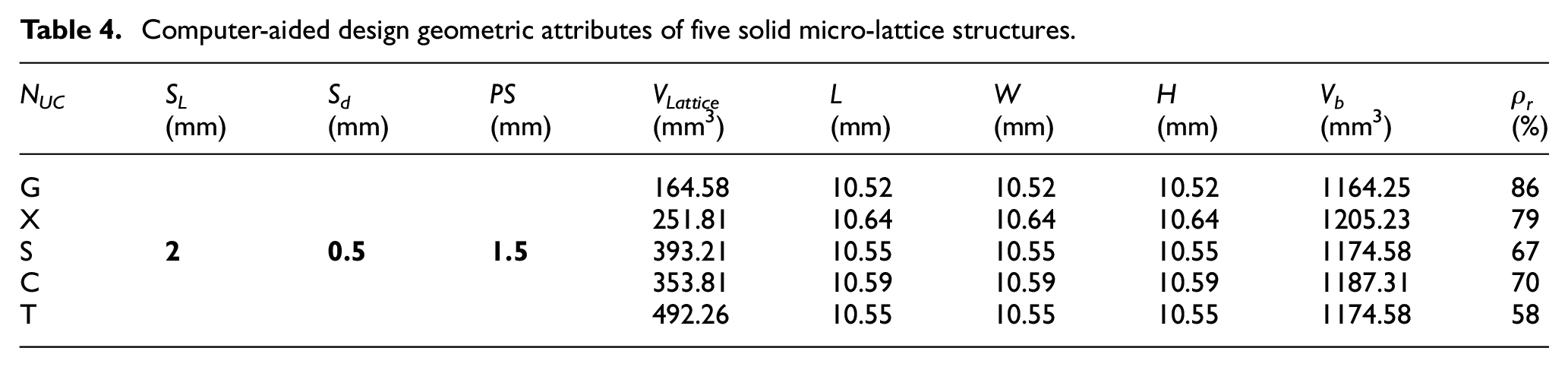
Here, the name of the unit cell (NUC), strut length (SL), strut diameter (Sd), pore size (PS), the volume of the micro-lattice structures (VLattice), length (L), width (W), height (H), the bounding box volume of the lattice structures (Vb), and the porosity percentage (
Computer-aided design geometric attributes of five solid micro-lattice structures.
2.3 Micro-lattice structural block
In this section, the proposed design has been used to develop a Ti6Al4V micro-lattice structure block, in which a unit cell is arranged in a 5 × 5 × 5 array within the lattice structure. Initially, the design of five different unit cell-based lattice structures of the same size means that the unit cell width (strut length) and diameter are 2 and 0.5 mm, respectively, as shown in Figure 5.
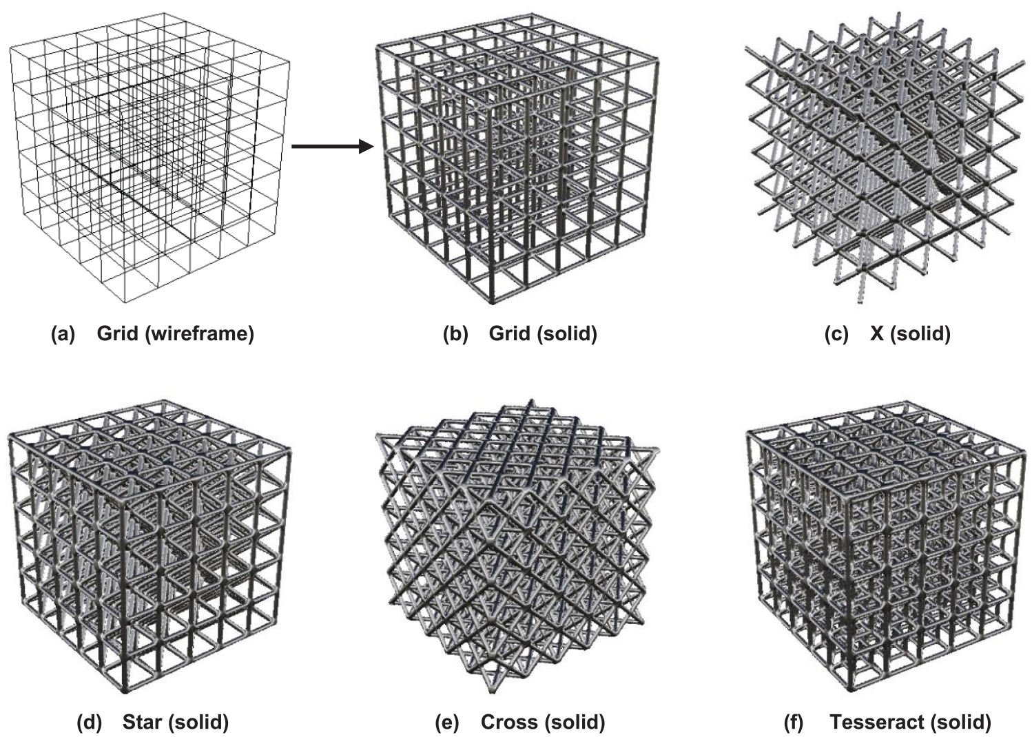
Grid wireframe transforms into the grid solid model; similarly, X, Star, Cross, and Tesseract lattice structures block into the 5 × 5 × 5 array.
Here, the lattice structures geometries were designed in both 3D wireframe and solid CAD models. The circular cross-section area over the wireframe trajectories of each lattice structure is
where Rn = Rg, Rx, Rs, Rc, Rt are the cross-section radii of the five unit cells [Grid (G), X (X), Star (S), Cross (C), and Tesseract (T)]; similarly, (ln = lg, lx, ls, lc, lt) is the total length of the struts. ρs is Ti6Al4V material density (i.e., 4320 kg/m3). The cuboid dimensions occupied by each unit cell are (xg, yg, zg), (xx, yx, zx), (xs, ys, zs), (xc, yc, zc), and (xt, yt, zt), respectively, and xn = yn = zn, as shown in Figure 6. The wireframe structural features of each cell show that the edge structure separates the shared edge into four divisions and the side edges of the interconnect vertex structure separate the edge into four divisions shared with adjacent unit cells, as presented by Zhong et al. [52]. The total strut length (lg, lx, ls, lc, lt) of these unit cells is represented in the following equations
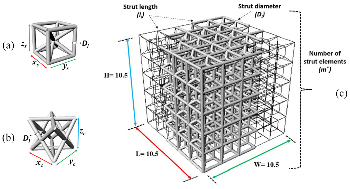
Schematic three-dimensional representation of unit cell topology: (a) Star unit cell; (b) Cross unit cell; (c) Tesseract lattice structure block (5 × 5 × 5 array) (all dimensions in mm).
All five unit cells were constructed as cuboid shapes (design space), and the cuboid external dimensions of each lattice structure blocks are the same: L = 10.5 mm, W = 10.5 mm, and H =10.5 mm. The total volume of the cuboid dimension or bounding box volume (Vb) and the structure volume (VLattice) of each lattice structure block with circular cross-sections are calculated by the following equations
Here, n* and i represent the total numbers of unit cell size (ith dimension) patterns arranged in the X, Y, and Z axes for obtaining the bounding box dimension. Similarly, m*, Di, and
3. Numerical modeling
This section defines the numerical modeling methods that were used to simulate the linear and nonlinear behavior of Ti6Al4V micro-lattice structure blocks under compressive loads. The FE simulations have been done using CAE software (Altair HyperMesh) [53] with beam and tetrahedral elements, and their FE results were compared to each other.
3.1 Meshing scheme/discretization
The FE mesh of the wireframe or solid lattice structure CAD model is solved by the numerical modeling method with defined loading and boundary conditions. Wireframe and solid CAD models were created by 3D modeling software and then saved into IGES and STL files format, respectively. The saved 3D geometries are used to import in commercial FE modeling software and then converted into FE models for further FE simulation analysis. Altair’s OptiStruct solver was employed to compute the FE results for both linear and nonlinear problems under static and quasi-static compression loading, respectively. In addition, the optimized mesh sized was determined for both beam and solid element models using the root mean square error (RMSE) method (see Section 3.3).
In this study, the two discretization methods have been utilized to predict the mechanical responses through the finite element method (FEM) of the given lattice structure block. The first method is two node beam elements to represent the struts with line mesh, including six degrees of freedom (DOFs) at each node, in total 2 × 6 = 12 DOFs. The circular cross-section area follows the line mesh trajectory that represents the strut diameter. The second method used is four node tetrahedron elements at three DOFs per node, in total 4 × 3 = 12 DOFs. The tetrahedron element is solid, and all solid elements only three translational DOFs (no rotational DOF). These elements are well formulated in 3D space, which helps one to accurately depict the stress distribution inside the lattice structure model against the loading conditions. Here, the general input data (Ti6Al4V material) have been used for FE simulation, which are the Young’s modulus (113.8 GPa), Poisson’s ratio (0.34), and material density (4432 kg/m3). The FE model of the cuboid shape lattice structure block is rigidly fixed at the bottom face nodes, and a uniaxial compressive force applied on the top face nodes. In addition, displacement boundary conditions (i.e., five DOF fix and one DOF along the Z-direction is free) have been applied on the surrounding cuboid lattice block to evaluate the crushing behavior of the lattice block from the top layer to the bottom. The same boundary conditions were used by Smith et al. [46].
3.1.1 Beam element
In this section, two-node (IJ) beam elements were used to model the lattice structure with a circular cross-section area, as shown in Figure 7. The same diameter (0.5 mm) is considered for all five lattice structure blocks, with no diameter changes in the nodal area. The strut geometry was a perfectly straight line to allow the mesh to be regular and not warped. At least six elements are used for the meshing of a single strut. The above-mentioned boundary conditions were applied to the bottom face nodes on the cuboid lattice block, which are fully fixed supported, while on the top face nodes, the total uniaxial compressive force is applied (parallel along the Z-axis) as in the distributed manner (i.e., force per node = total force divided by the selected number of nodes on the top face). Next, the same boundary and loading conditions were applied to all five FE models.
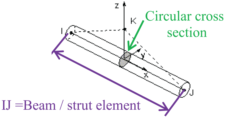
Schematic beam element with a circular cross-section.
This discretization method is based on Timoshenko beam theory with the quadratic shape function. Accordingly, such FE model is suitable to describe the shear and bending effects on the structure. An analytical solution, the Timoshenko beam theory concept is used to calculate the initial stiffness by considering the bending effect of a single strut, while the full plastic moment theory is used to predict the plastic collapse strength [54].
3.1.2 Tetrahedral element
The tria or triangle two-dimensional (2D) element includes three nodes, although, in three dimensions, a tetrahedral element consists of four nodes at the corners (see Figure 8). In this section, the FE model of a lattice structure block has been discretized using tetrahedron elements with the quadratic interpolation function, whereby the initial stiffness value is calculated within the structure through FE analysis. It has an advantage over beam elements, and it allows us to map meshing in CAD geometry completely with adjustable mesh features. The boundary conditions were applied, which were the same as those applied for beam element-based FE models.
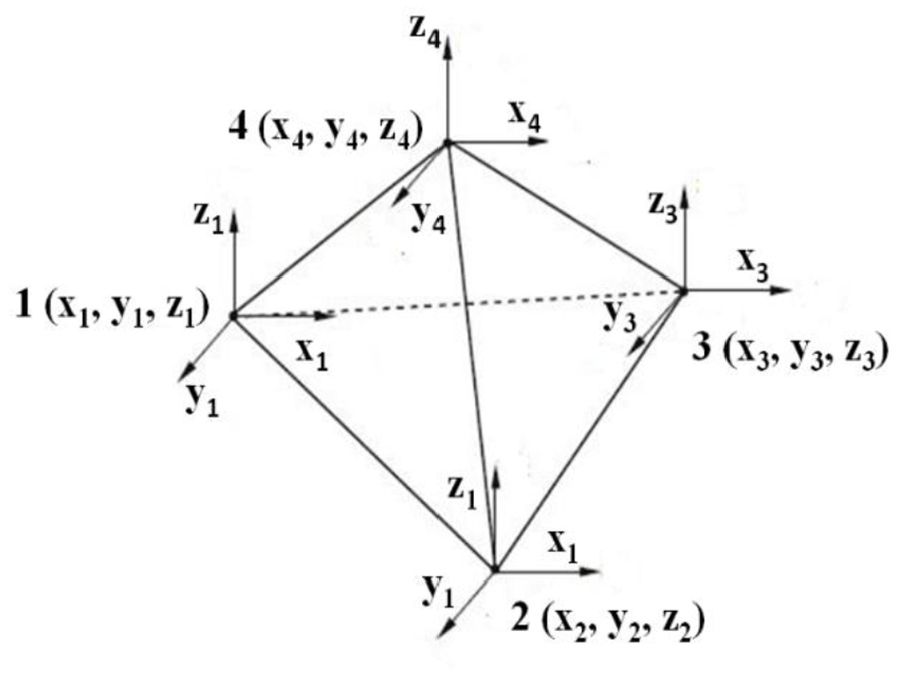
Shape function of the tetrahedral finite element.
In addition, the mesh convergence study was performed using the RMSE estimation technique, and an optimized meshed size has been used for linear analysis. Meanwhile, for nonlinear analysis, an adaptive meshing methodology was adopted, by which the mesh is automatically refined on the high-stress concentration area. With the help of 3D modeling software, the solid lattice structure model was generated on the Rhino3D interface platform. The generated model is actually in the form of numerous small triangular 2D facets or a poly-surface, that is, its edges are joined corresponding to other 2D facet edges and represent a 2D watertight mesh structure. It looks like a solid model, but the lattice structure surfaces are made with many triangular 2D facet forms. Therefore, the generated CAD models in the Rhino3D software platform were saved into STL file formats. In this study, the STL file format is used to import into a commercial FE software for further FE simulation analysis. This software has strong FE tools available, whereby converting 2D mesh files into 3D tetrahedron elements takes a few minutes time. To obtain better FE results, a mesh quality check option is used to identify failed elements within the FE model. Once the failed elements are identified, then mesh corrective FE tools are used to control them easily and achieve quality mesh.
3.2 Material model for the Ti6Al4V lattice structure block
This section presents an evaluation of the elastic and elasto-plastic material properties of given lattice structures by using the FEM. The mechanical responses of lattice structures at various loading and boundary conditions commonly depend on the selected material and also the geometric attributes, such as cell configuration, strut diameter, pore size, relative density, etc. The FE modeling approach includes both elements to develop the lattice structure of FE models and analyze the defined assumptions.
For the characterization of elastic material properties within a structure, a simple linear static FE analysis was performed; for nonlinear analysis, a Johnson–Cook material model is used, which describes the elasto-plastic behavior. A similar model was adopted by Kadkhodapour et al. [48], who investigated using this model to predict the plateau stress and maximum stress at the first peak with less than 18% error. The obtained FE nonlinear stress–strain curve results for the Ti6Al4V lattice structure are well formulated by the Johnson–Cook material model (1983). This model describes the stress flow in the material as a function of strain, strain rate, and temperature effects
where
3.3 Mesh sensitivity study
The FE commercial software Altair Optistruct is used to prepare and analyze the FE model of Ti6Al4V micro-lattice structures. Here, as an example, Star micro-lattice structures (5 × 5 × 5 array) were designed, which includes both wireframe and solid CAD models of the same unit cell size for FE mesh sensitivity analysis, shown in Figure 9. The strut diameter and length of a given lattice structure are 0.5 and 2 mm, respectively. This study was performed for both element-based FE models to comprehend the relationship between element sizes and material properties. Figures 10 and 11 demonstrate the FE results of beam and tetrahedral element-based lattice structures, which were subjected to the same uniaxial loading and boundary conditions.
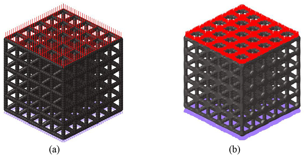
A Star Ti6Al4V micro-lattice structure used for mesh sensitivity analysis: (a) beam element-based finite element (FE) model; (b) tetrahedral element-based FE model.
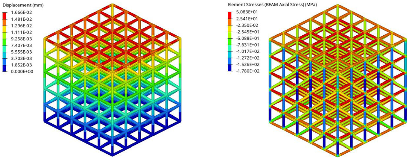
Beam element-based finite element results of the Star Ti6Al4V micro-lattice structure.
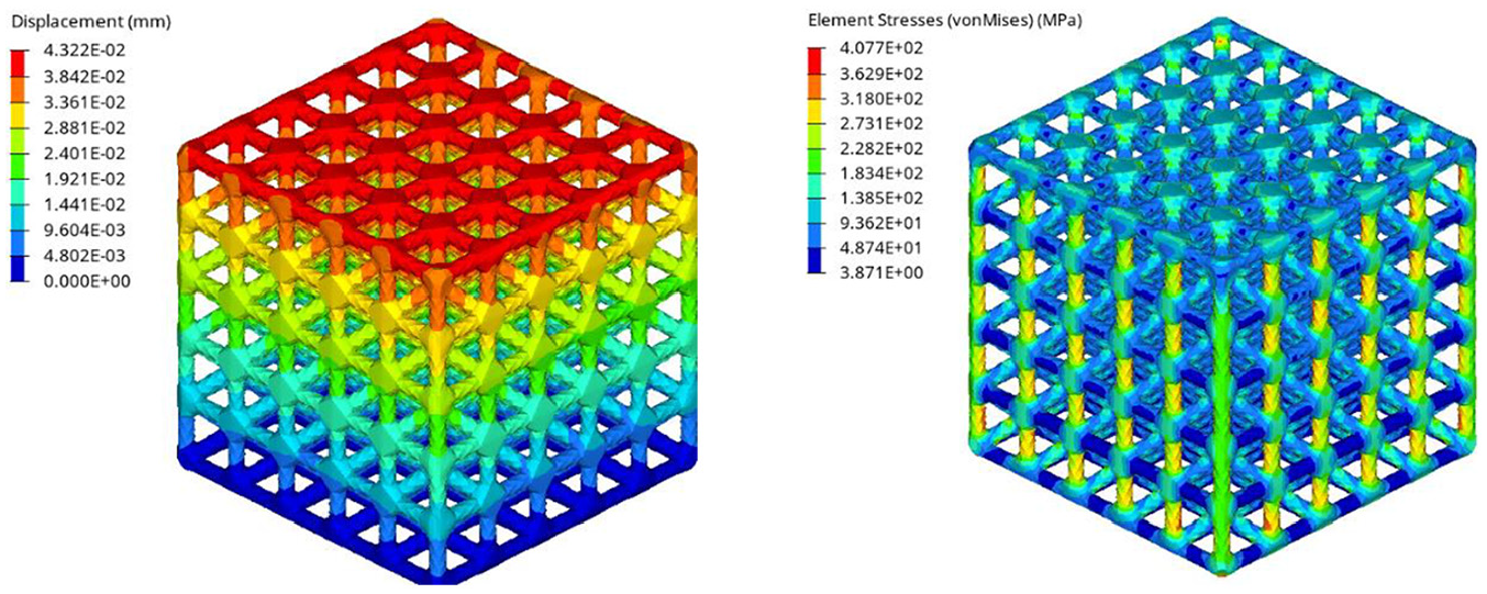
Tetra element-based finite element results of the Star Ti6Al4V micro-lattice structure.
A simple linear static FE analysis was performed to optimize the mesh size on both the elements and a RMSE method was employed, whereby a mesh size independence with respect to structural geometry has been checked accurately and further can be implemented for other FE models. The method for the mesh independence check on beam and tetrahedral element-based FE models is elaborated in the following sections (a) and (b), respectively.
The ratio of strut length (SL) to element division (xi) was taken as a dimensional parameter. The stress at predefined nodes having specific spatial locations was computed in each numerical run, and the dimensional parameter was increased by an arithmetic progression of 2 in consecutive runs. The RMSE value was computed as the square of stress difference for successive runs and taken as the index to near-exact solution. This was repeated until the index to near-exact solution reaches a nearly steady value. A similar method was used by Kumar et al. [55] to identify the effect of the dimensional parameter on the near-to-exact solution index. The result of the mesh independency test is presented in Figure 12(a). It can be seen that there is a sharp fall in the near-to-exact solution index with damping oscillations, as the dimensional parameter (SL/xi) is increased. For (SL/xi) (2/8) = 0.25, hence (SL/xi) > 8, the index becomes nearly steady with stress difference less than 10−2 in successive runs. In the present simulation study, (SL/xi) (2/6) = 0.33 is used, which corresponds to an element size of 0.33 mm.
Similarly, the same approach is used to check mesh size independence for solid elements. Here, the solid CAD model was meshed with the solid (tetrahedral) element and the same loading and boundary conditions were applied on the beam element-based FE model. The criteria to select the solid mesh size are not the same as those of the beam element. The solid structural model was meshed with five different (0.1, 0.15, 0.2, 0.25, and 0.3) mm element sizes, individually, and the FE simulation was run to compute the maximum stresses within the structures, illustrated in Figure 12(b). It can be seen the variation of stresses versus element sizes in the same micro-lattice structure model is subject to the same compressive load consideration. Thus, the optimized solid element size has been found to be 0.25 mm, which is applied to all the solid lattice structure models for FE linear static analysis.
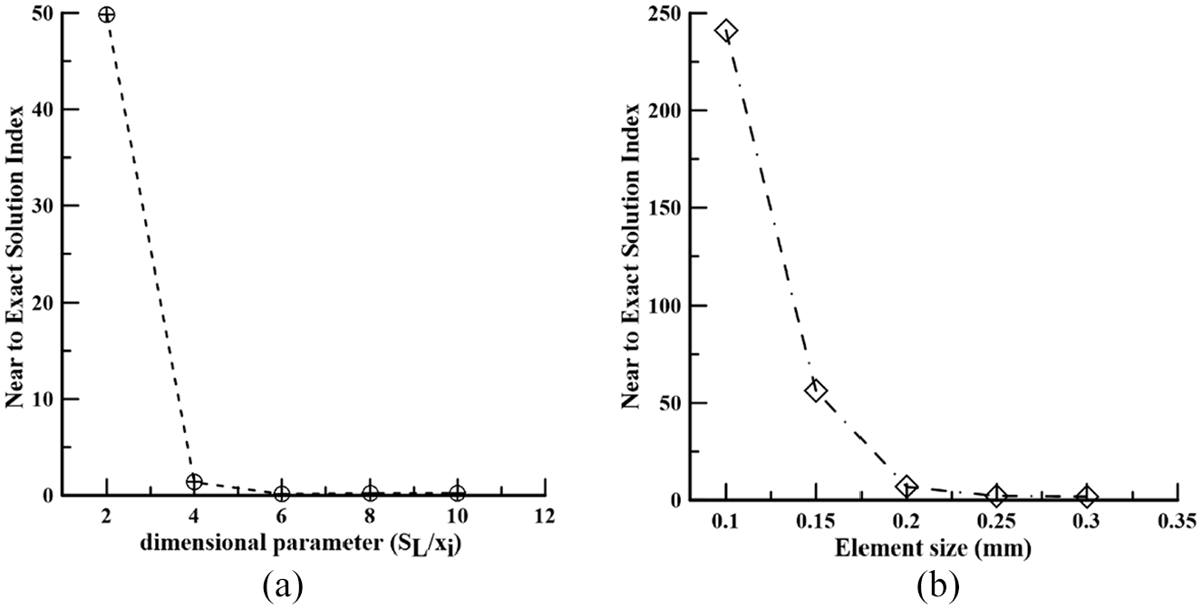
Mesh sensitivity analysis study of the Star micro-lattice structure: (a) effect of the dimensional parameter on the near-to-exact solution index for beam elements; (b) effect of element size on the near-to-exact solution index for tetrahedral elements.
4. Validation
This section demonstrates a validation study of FE analysis using the Merkt et al. [49] experimental work. Merkt et al. [49] experimentally has investigated the elastic and plastic deformation behavior of Ti6Al4V cuboid shape lattice structures blocks with different strain rates: quasi-static and dynamic compression loading. The authors used various types of unit cell-based lattice structure blocks of the same size, fabricated by the SLM method, and performed compression tests to determine which lattice structure was the best among all of them. The cuboid lattice blocks were designed into 8 × 8 × 8 unit cells at fixed strut diameter and cell width of 0.35 and 2 mm, respectively. It was found that the F2CC-Z unit cell-based lattice structure demonstrates excellent mechanical properties. Thus, a similar model was created using INTRALATTICE software and then nonlinear FE analysis was performed. In this study, two FE models are developed, namely beam and tetrahedral. Simulation was done using OptiStruct Solver. The obtained stress–strain curves through the FEM depicted that the initial yield stresses of both FE models are much deviated from the Merkt et al. [49] experimental curve, while the elastic properties with respect to strain measurement of the beam elements deviate a great deal and are illustrated in Figure 13. Consequently, it is concluded that the stress–strain curve of solid element FE models is near to that of the experimental test results.
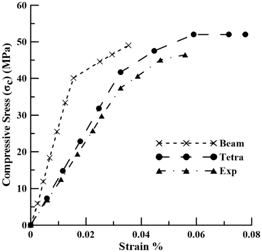
A schematic representation of the compressive quasi-static results of finite element (beam and tetra element-based) models from the Merkt et al. [49] experimental work.
5. Results and discussion
Initially, wireframe and solid CAD models of all five different micro-lattice structures (G, X, S, C, and T) were used for static linear and nonlinear FE analysis with defined compressive loading and boundary conditions. For all lattice structures, the unit cell geometry size (SL– 2 mm, Sd– 0.5 mm), Ti6Al4V material properties, and their configurations (5 × 5 × 5 array) were the same. The CAD models were converted into FE models for the FE simulation study. Here, instead of CAD wireframe and solid models, the beam and tetrahedral element-based FE models are employed, respectively. The linear static FE analysis results for both elements is illustrated in Figure 14. Accordingly, the Star based micro-lattice structure block represents a high stiffness value. In addition, it is found that the tetrahedral element-based FE model simulation results of all lattice structures are more varied while subjected to the same loading condition.
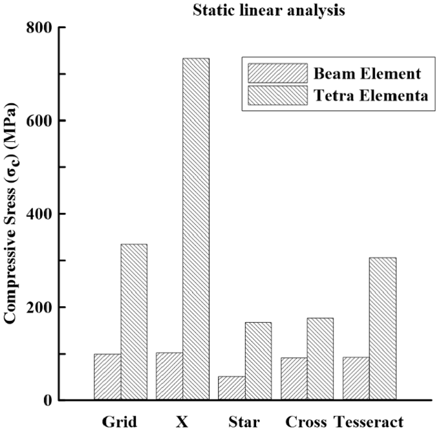
Comparison of linear static analysis for five different lattice structures with tetrahedral and beam element-based finite element models.
Therefore, for further nonlinear analysis, tetrahedral FE models have been used. The FE analysis and simulation results show that the deformation behavior occurs in Grid, Star, and Tesseract lattice-based structure blocks as the stretching-dominated mode, and while that in the X and Cross lattice blocks is in the bending-dominated mode. However, the orientation of struts in Grid, Star, and Tesseract lattices were all parallel and perpendicular to the loading direction, while in the case of X and Cross lattices, the struts were inclined relative to the loading direction, and therefore stretch-dominated and bending-dominated behavior was expected, respectively. Figure 15 represents the nonlinear FE analysis results in terms of compressive stress–strain curves. The Star unit cell-based micro-lattice structure has high compressive yield stress (83.39 MPa) compared to the other lattice structure blocks. Thus, from the linear and nonlinear FE analysis results, it is found that the Star unit cell-based lattice structure demonstrates the best mechanical properties during uniaxial loading conditions.
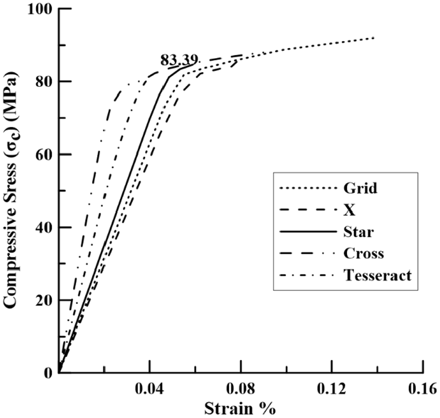
Nonlinear static analysis for five different lattice structures with three-dimensional tetra element-based finite element models.
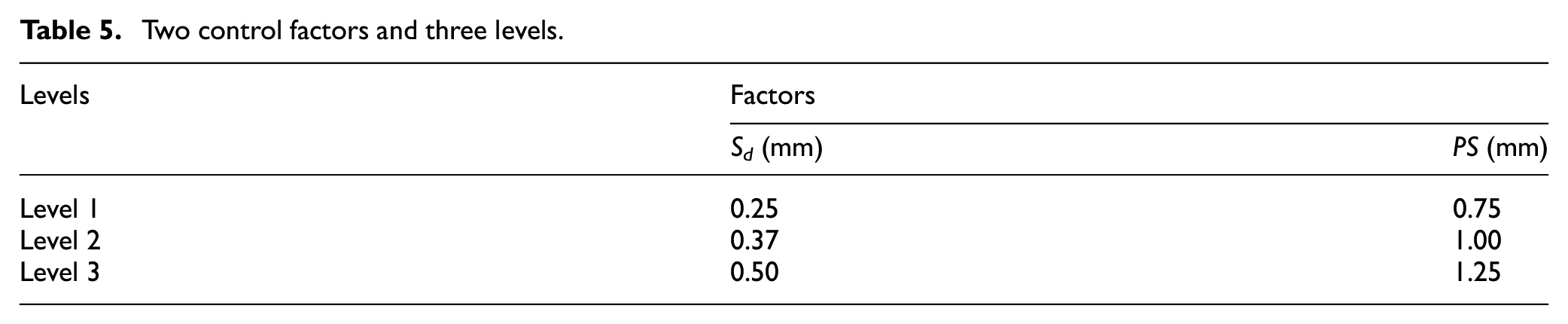
Subsequently, the Star lattice configuration (5 × 5 × 5) was constructed at two design variables and three levels, namely strut diameter (Sd– 0.25, 0.37, and 0.5) mm and pore size (PS– 0.75, 1, and 1.25) mm at fixed strut length (SL– 2) mm, which are shown in Table 5. Next, the Taguchi-based optimization technique with L9 orthogonal array was used to determine the optimum variables (see Table 6). The Taguchi method involves reducing the variation in a process through the robust design of experiments (DOE). Consequently, the maximum initial yield stress of 85.50 MPa was obtained when designed at the optimum variables of Sd– 0.25 mm and PS– 0.75.
Two control factors and three levels.
Design L9 Taguchi orthogonal array with two factors and three levels using MINITAB.
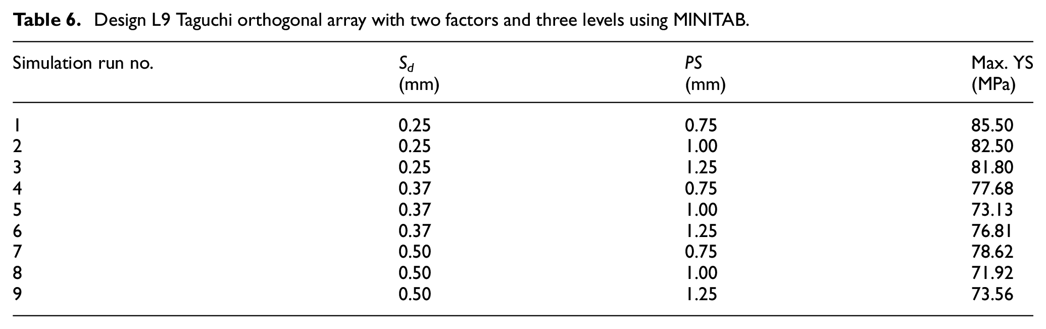
Further, an analysis was carried out the using the linear regression method by MINITAB software, and a mathematical expression has been established, shown in the following equation
Based on the aforementioned static linear and nonlinear analysis, it is found that the Star lattice structure has low compressive stress and high yield strength compared with all other types of lattice geometries. Therefore, the Star lattice structures blocks were designed (5 × 5 × 5 array) by heterogeneous solid gradient mesh (discussed in Section 2.2). The geometric design variables have been selected as strut length (SL– 2) mm and maximum and minimum strut radius (Rmax and Rmin). The strut trajectory is followed by the type of gradient function (i.e., linear, centered, and cylindrical) toward the X, Y, and Z axes. The term ‘A’ and ‘B’ represent the Star lattice structure design at two main conditions, which are without swapping and with swapping of Rmax and Rmin values (see Table 3), respectively. However, here, the two variables of strut radius 0.50 and 0.25 mm are used for designing heterogeneous gradient solid mesh. The term ‘B’ is the reversed gradient of term ‘A,’ which just means swapping the given Rmax and Rmin values. Figures 16–18 show the design of Star lattice structure blocks with consideration of three types of gradient in three principal axes (X, Y, and Z) and that have two swapping conditions, ‘A’ and ‘B.’ Thus, a total of 18 Star lattice structure blocks was designed. The linear-gradient function designed ‘A’ and ‘B’ models look symmetric (i.e., AL-X and BL-X, AL-Y and BL-Y, AL-Z and BL-Z), while their orientation changes according to the X, Y, and Z axes direction, which is shown in Figures 16 and 17. Similarly, ACent-X and ACent-Y, BCent-X and B-Cent-Y designed models are symmetric. The linear static FE results (von Mises stress) of the aforementioned models are nearly identical, for example, AL-X = 623.31 MPa and BL-X = 613.07 MPa (illustrated in Table 7).
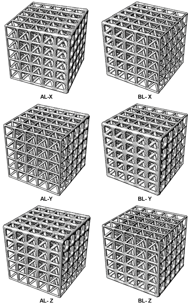
Linear type of gradient function to design Star lattice structures (5 × 5 × 5 array) at two swapping conditions, ‘A’ and ‘B.’
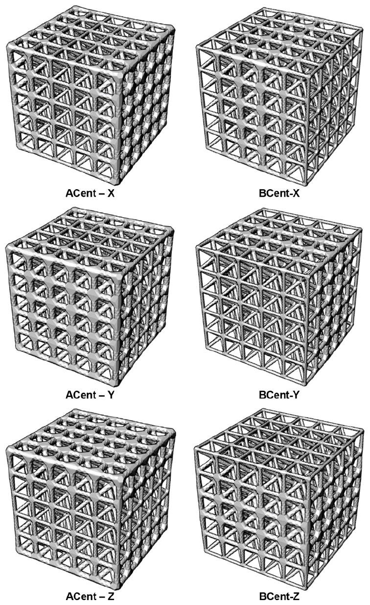
Centered type of gradient function to design Star lattice structures (5 × 5 × 5 array) at two swapping conditions, ‘A’ and ‘B.’
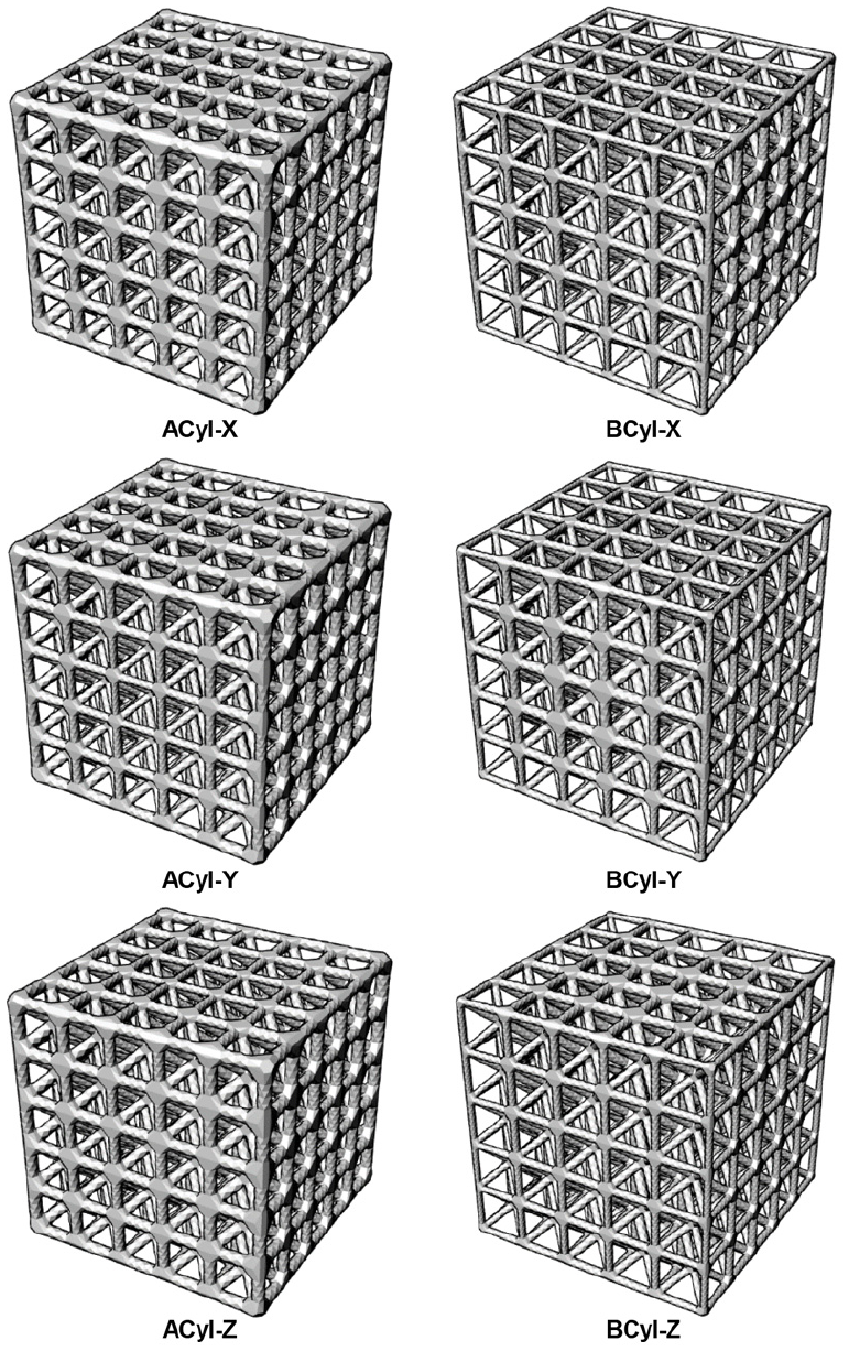
Cylindrical type of gradient function to design Star lattice structures (5 × 5 × 5 array) at two swapping conditions, ‘A’ and ‘B.’
Compressive stresses results from finite element (FE) static linear analysis of all 18 Star lattice structures.
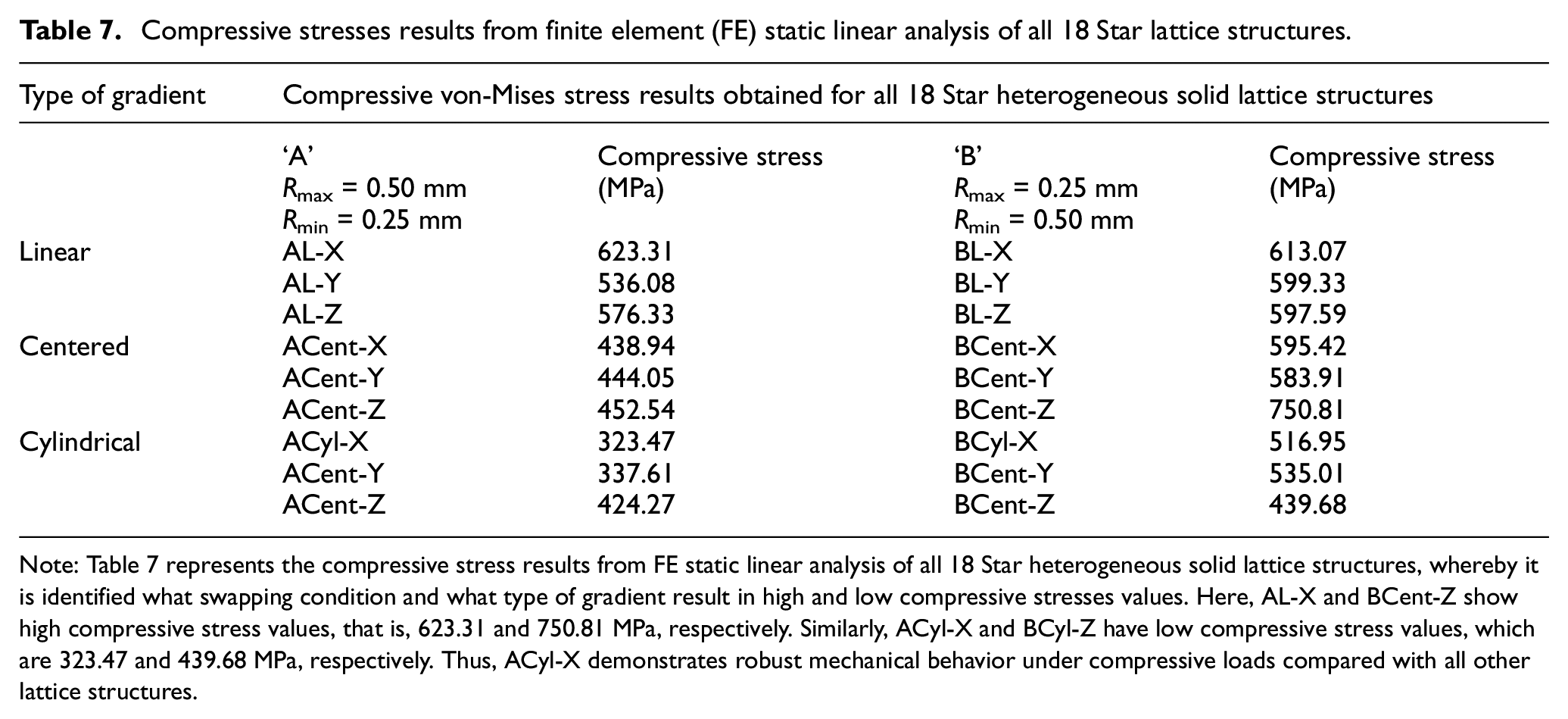
Note: Table 7 represents the compressive stress results from FE static linear analysis of all 18 Star heterogeneous solid lattice structures, whereby it is identified what swapping condition and what type of gradient result in high and low compressive stresses values. Here, AL-X and BCent-Z show high compressive stress values, that is, 623.31 and 750.81 MPa, respectively. Similarly, ACyl-X and BCyl-Z have low compressive stress values, which are 323.47 and 439.68 MPa, respectively. Thus, ACyl-X demonstrates robust mechanical behavior under compressive loads compared with all other lattice structures.
Subsequently, individually the FE static linear analysis has been performed for all 18 Star lattice structures with defined uniaxial loading and boundary conditions (Figures 19(a)–(c)). In addition, their FE results were compared (Figure 20), whereby it may determined what type of gradient structure could be designed, which has demonstrated robust mechanical behavior structure among all 18 Star lattice structures. Thus, it helps if some modification is needed in the design of the lattice structures, as we can so easily regulate the design by choosing gradient types, and swapping conditions without changes in the porosity.
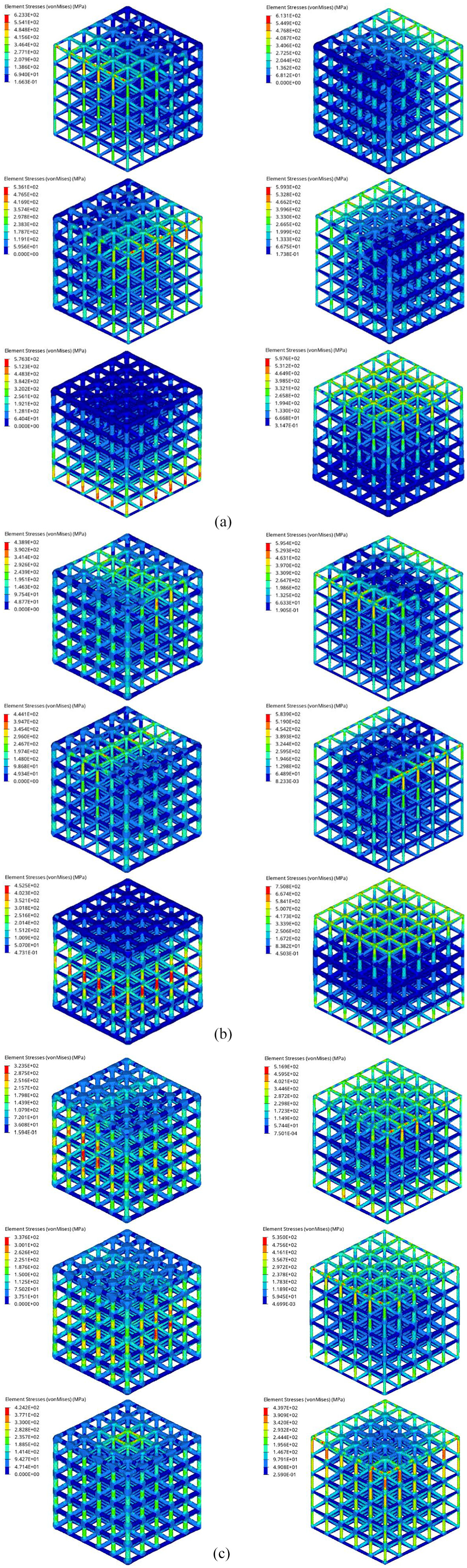
(a) Von Mises stress results of heterogeneous linear-gradient Star lattice structures (5 × 5 × 5 array). (b) Von Mises stress results of heterogeneous centered gradient Star lattice structures (5 × 5 × 5 array). (c) Von Mises stress results of heterogeneous cylindrical gradient Star lattice structures (5 × 5 × 5 array).
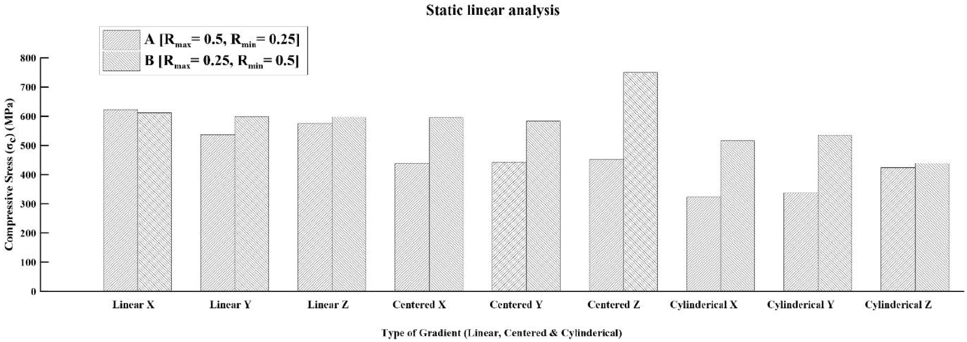
Comparison of von Mises stresses results of three gradient types of Star lattice structures at the ‘A’ and ‘B’ conditions.
The design of custom structures (such as patient-specific implants or scaffolds) has been a theme of intensive research and development for decades. In future research work, for achieving the effective mechanical properties of lattice structured material, these innovative modeling approaches will be in good agreement. Further, we would utilize this modeling approach with different custom unit cells (i.e., octet, cuboctahedron, diamond, and hexagonal) to design either regular or gradient-based lattice structures for defined shape volume object. In addition, we can predict the mechanical characterization of these lattice structure material fabricated by direct metal laser sintering by computer-aided engineering (CAE) software. For better FE prediction results, if there are alterations needed to the design of the lattice structure at any place in the 3D-CAD models, then geometrical attributes could be easily modified and incorporated. Lastly, experimental validation will be carried out also in order to confirm the FE results.
6. Conclusion
In this article, the Ti6Al4V micro-lattice structure modeling and simulation for additive technology was studied. Preliminary, the main finding was to estimate the compressive behavior of five different types of lattice structures under defined uniaxial compressive loading and boundary conditions through CAE software. The mechanical response of different micro-lattice structures depends upon two aspects – (a) the type of unit cell topology and its configuration (n×n×n) and (b) The gradient type of lattice structure placed in position or orientation under loading directions.
In the first part, a design methodology was proposed to create periodic wireframe and solid homogeneous and heterogeneous micro-lattice structures with defined design parameters. Using design parameters, design engineers can easily regulate CAD geometries as per design requirements.
In the second part, a mesh sensitivity study was performed by using both beam and 3D continuum elements to generate FE models of the lattice structures. The RMSE method was employed for mesh sensitivity analysis, whereby further static linear FE simulation study is done with an optimized meshed sized for both the elements. The nonlinear FE simulation results showed good agreement with the deformation mechanism of lattices, such as for bending-dominated structures (X and Cross), in which deformation was accompanied by the shearing effect of 45 degrees, while the Grid, Star, and Tesseract lattice structures were shown to undergo stretch-dominated deformation. Accordingly, this study can raise the understanding of the deformation and failure mechanism effects of different lattice structures.
In this study, it has been found that ‘Star’ has low compressive stress and high initial yield stress as compared to Grid, X, Cross, and Tesseract unit cell-based structures. Moreover, the Star unit cell has been configured into 5 × 5 × 5 array at two design variables and three levels, namely the strut diameter (Sd– 0.25, 0.37, and 0.5) mm and pore size (PS– 0.75, 1, and 1.25) mm. After, the Taguchi-based DOE technique was used with the L9 orthogonal array. Consequently, the maximum initial yield stress of 85.50 MPa was obtained when designed at the optimum variables of Sd– 0.25 mm and PS– 0.75 mm and then we developed an analytical model.
Finally, the Star lattice structure blocks (5 × 5 × 5 array) are re-modeled using heterogeneous solid gradient mesh with two swapping conditions, ‘A’ and ‘B.’ The term ‘B’ is the reverse of the gradient of term ‘A,’ which means just swapping the given Rmax and Rmin values. The geometric design variables are the strut length (SL– 2) mm and maximum and minimum strut radius (Rmax and Rmin). Thus, a total of 18 Star lattice structure blocks was designed. The two variables of strut radius of 0.50 and 0.25 mm are used for designing heterogeneous gradient solid mesh. The FE simulation results and their comparison has shown that AL-X and BCent-Z show high compressive stress values, that is, 623.31 and 720.81 MPa, respectively. Similarly, ACyl-X and BCyl-Z have low compressive stress values, which are 323.47 and 439.68 MPa, respectively. Thus, ACyl-X demonstrates robust mechanical behavior under compressive loads compared with all other lattice structures. The FE results suggest that to achieve potential mechanical properties one needs to change the appropriate design parameter of lattice structures, whereby these structure materials can be used in various engineering application, such as implant design, scaffold design, heat exchangers, etc.
