
Abstract
A method proposed earlier, relying on the use of harmonic Cartesian polynomial and rational functions, is extended here to find a semi-analytical solution to the uncoupled, two-dimensional problem of thermo-magnetoelasticity for a system of long parallel, non-intersecting, transversely isotropic elastic cylindrical electrical conductors. Results are presented for two conductors of equal circular normal cross-sections carrying currents of equal densities flowing along the same direction, subjected to Robin-type thermal boundary conditions. Quantities of practical interest are represented graphically and discussed. Consideration of a system of electrical conductors is of practical importance in power plants and in various technological instruments, where it is required to assess the interaction between conductors. The obtained formulas for the magnetic vector potential may be of importance for the determination of the coefficients of self- and mutual inductance of long electric conductors, otherwise difficult to calculate by standard methods. Comparing the results with those of a single conductor allows us to assess the interaction between conductors.
Keywords
1. Introduction
A system of long elastic electrical conductors carrying uniform, steady axial currents deforms under the combined action of Joule heat in the bulk, and the magnetic forces that are equivalent to a distribution of surface forces in the quasi-electrostatic approximation. Such a system of electrical conductors is found in electrical power stations in the form of busbars, and in other electrical instruments. An important task is to find the deformations and the stresses occurring in the cylinders, in order to secure safe functioning.
It is known that the associated mathematical problem reduces to the determination of a number of harmonic functions linked to one another by some thermal, magnetic, and mechanical boundary conditions.
If the thermal problems are usually solved separately for each conductor, the magnetoelastic aspect of the problem involves interaction between the conductors due to the magnetic field distribution in the whole space.
There is little work available in the literature devoted to static thermo-magnetoelasticity of long electrical conducting cylinders carrying a uniform steady current. We cite [1–4] for circular, elliptic and rectangular boundaries and the calculation of Lorentz force-induced stresses in long straight conductors carrying a uniform current, and [5–9] for elliptic or square boundaries by boundary integrals and under different boundary conditions including a numerical approach.
The present work extends a previous paper [11] to the case of multiple parallel, non-intersecting conductors in which the steady axial currents may be flowing in any one of two possible directions. Its aim is to provide simple means for evaluating the deformation and stresses occurring in these conductors under Joule heat and their own magnetic field, in addition, possibly, to other external factors. Such a model finds important application in electrical power plants and in various technological instruments where groups of conductors are found. Here, the interaction between these components needs to be investigated. This, in turn, guarantees a safe performance of such a structure under working conditions (cf. [10]). Again, the study of a system of electrical conductors allows to assess the elastic interaction between them, on the basis that each conductor contributes to the total magnetic field distribution of the system in space. The obtained results for the magnetic field may be considered as approximations to those for conductors with finite configuration and, thus, have an extended range of validity. The method may be easily adapted to deal with the cases where an external magnetic field is applied, or to a system of parallel, non-conducting magnetic cylinders placed in an external transverse magnetic field. Solution of the magnetic problem provides formulas for the magnetic vector potential everywhere in space, which may be of interest in calculating in a relatively easy way the coefficients of self- and mutual inductances for a system of long cylindrical electric conductors, otherwise a difficult task to achieve (see, for example, [12, 13]. On the basis of the present results, other problems of electromagnetism may be resolved. For example, by taking the radius of one conductor sufficiently small, one finds the magnetic field distribution for a long conductor placed a distance apart from an infinite parallel wire carrying a current.
The method relies on the use of Cartesian polynomials and rational functions to generate a system of harmonic functions involved in the solution in the form of expansions. These harmonic functions are inter-related by the boundary conditions. The coefficients intervening in these expansions are determined numerically by boundary collocation. The method allows to simply resolve a difficult Poisson’s equation arising in the elasticity problem. Thus, the method produces a semi-analytical solution and may be used for general geometries of the normal cross-section of the conductors.
The basic equations and accompanying conditions are presented in brief. Details may be found in [11]. For simplicity, results are provided for two circular conductors of the same material having the same radius, with currents flowing in the same direction. A simplified thermal boundary condition makes it possible to direct the main effort towards the resolution of the magnetoelastic problem, for which the interaction between different conductors is conditioned by the magnetic field of the system. All quantities of practical interest are represented graphically and discussed. In particular, results are compared with those for a single conductor.
2. Problem formulation
Consider a system of long, parallel non-intersecting elastic cylindrical conductors of homogeneous, transversely isotropic materials. The cylinders carry steady, uniformly distributed axial electric currents flowing in one of two possible directions and are placed in an ambient medium (vacuum) of steady constant temperature
A system of orthogonal Cartesian coordinates
Geometry of the problem: multiple non-intersecting conductors. The currents and the magnetic vector potentials are parallel to the cylinders’ axes.
The parametric equations of the i th cross-sectional contour are of the form:

where

respectively, with

3. Basic field equations and boundary conditions
The governing equations of static, linear uncoupled thermo-magnetoelasticity are quoted here without proof as presented in [7]. These are solved under prescribed proper mechanical and thermal boundary conditions. The model takes into account the dependence of the magnetic permeability on strain. In addition, the equations are complemented with the usual mechanical condition of continuity of the total stress vector across the boundary, and the magnetic boundary conditions expressing the continuity of the magnetic scalar or vector potential and the normal component of the magnetic induction in the absence of surface electric currents.
3.1. Equation of heat conduction
The temperature T, as measured from a reference temperature

where K is the coefficient of heat conduction and
3.2. Equations of magnetostatics
The magnetic vector potential is everywhere parallel to the axes of the cylinders, along the z-axis, with component denoted by A. Vanishing of its divergence is automatically satisfied. Thus, in each conductor:

where
In the surrounding vacuum labeled “*” one has

3.3. Equations of elasticity
The basic equation in each conductor is the biharmonic equation for the stress function U (cf. [5, 7]):

of which the general solution is expressed in terms of two basic harmonic functions

and

The constants
The stress tensor components

where the commas in the subscripts mean differentiation with respect to the shown variables.
The stress components are expressed in terms of


The mechanical displacement vector components in Cartesian coordinates are expressed as


where
The tangential component
The boundary conditions associated with the mechanical problem may be one of the following: either the displacements or the total stresses are prescribed on the boundary; or otherwise mixed conditions. In the first case, one uses relations (14), (15) or (16), (17). For the second case, one needs the following relations, necessary to formulate the continuity of the total stress (involving Maxwell’s stress tensor) across the boundary:
1. continuity of the total stress


where
2. external forces
and
3. Maxwellian stress

with


3.4. Elimination of rigid-body motion
The elimination of rigid-body motion from the obtained elastic solution and the additional conditions imposed on the stress function and its derivatives at some chosen point on each contour yield equations relating the functions
1. Conditions for eliminating the rigid-body translation at the centers of the cylinders


2. Conditions for eliminating the rigid-body rotation at the centers of the cylinders

The form of these equations may vary when the point at which the conditions are set is different from the origin.
4. The method of solution
4.1. Construction of harmonic functions
As may be noted, the solutions of the thermal, magnetic, and mechanical problems involve several harmonic functions inside the conductors and in the outer region as well. These functions will be determined in the form of properly chosen expansions in polynomial or/and rational Cartesian harmonics as explained in [11]:

the values of M and N may be different for the different harmonic functions. The real and the imaginary parts of function

whereas their counterparts derived from

There are many possibilities to generate such harmonic functions and this will be used to reduce the errors in satisfying the boundary conditions. Under any choice, we shall require that the expansions for the magnetic vector potential inside the conductors include exclusively polynomial terms. This condition is necessary, as it allows us to easily find the solution of the arising Poisson’s equation (9).
The next step is to satisfy the thermal, magnetic, and mechanical boundary conditions, together with the conditions for eliminating the rigid-body motion and the additional conditions at two chosen points in the conductors. The use of boundary collocation yields three systems of linear algebraic equations to calculate the coefficients in the expansions for the different harmonic functions and the constant intervening in the expression for the magnetic vector potential at infinity. As a result, all quantities of practical interest are determined everywhere inside the conductors and in the surrounding space.
4.2. Estimation of the error
All field equations are satisfied rigorously. The only errors to be taken care of are those arising from the solutions of three systems of linear algebraic equations mentioned previously for the thermal, magnetic, and mechanical problems. Any of these rectangular systems of linear algebraic equation in matrix form

is reduced to a square system by the transformation

where superscript T denotes the transpose. Solution then follows by least squares. If Z denotes the obtained solution of this last system, the error in satisfying the system of equations is defined as

For each problem, there will be three errors,
5. Application
As the thermal problems for the different conductors are usually treated independently, these problems can be dealt with as explained for a single conductor. The application considered here concerns two parallel, non-intersecting cylindrical conductors of the same material and of equal circular normal cross-section, placed a distance apart. The circles have radius a and are centered at the points
A Robin thermal condition is prescribed on each of the boundaries in the form:

where Bi is Biot constant and
The general solution of (4) is

where

Other geometries and thermal boundary conditions may be treated equally well.
The solutions of equations (5), (6) are looked for in the form

The boundary conditions for the magnetic problem, in the absence of surface electric currents, reflect the continuity of the tangential component of the magnetic field and the normal component of the magnetic induction. They are expressed as [5, 7]


together with the radiation condition

The magnetic field is obtained from the relation:

The mechanical boundary conditions express the continuity of the total stress at the boundaries, taking into consideration only the Maxwellian stress in the region outside the conductors.
All equations are taken in dimensionless form. For this, introduce the dimensionless quantities


and two dimensionless parameters

For definiteness, calculations have been carried out with collocation nodes uniformly distributed with respect to the central polar angle on each contour. The values of the different dimensionless material parameters were taken the same for both conductors, with values

In addition, the parameter entering the expression for the magnetic vector potential far away from the conductors was chosen
5.1. Temperature
We consider a simple thermal problem in order to concentrate on the magnetoelastic aspect for which interaction between the different conductors takes place. The conductors will be labeled
The external dimensionless temperature is taken as

The following results were obtained for

and

We present the results for the first cylinder only. The temperature distribution in the first cylinder, as well as the temperature displacements at the boundary, are shown in Figures 2–4. The distribution of magnetic vector potential in a region containing the two cylinders is represented on Figure 5.
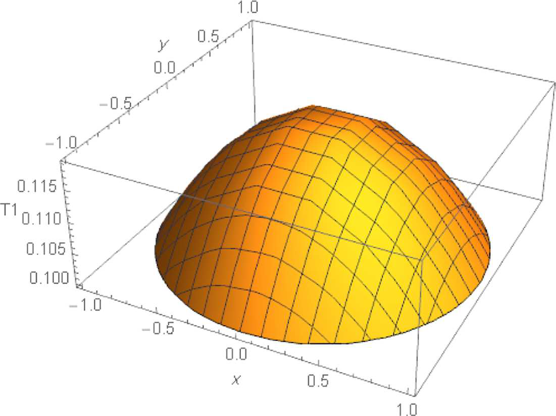
Distribution of temperature in a normal cross-section of the first cylinder.
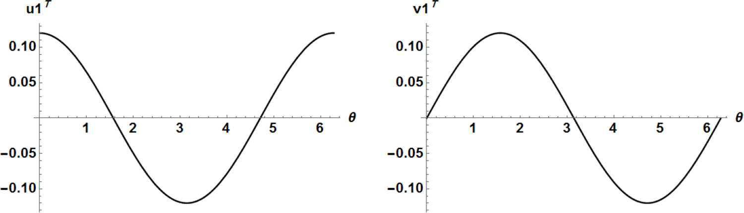
Boundary temperature displacements for the first cylinder.
Normal boundary temperature displacements for the first cylinder.
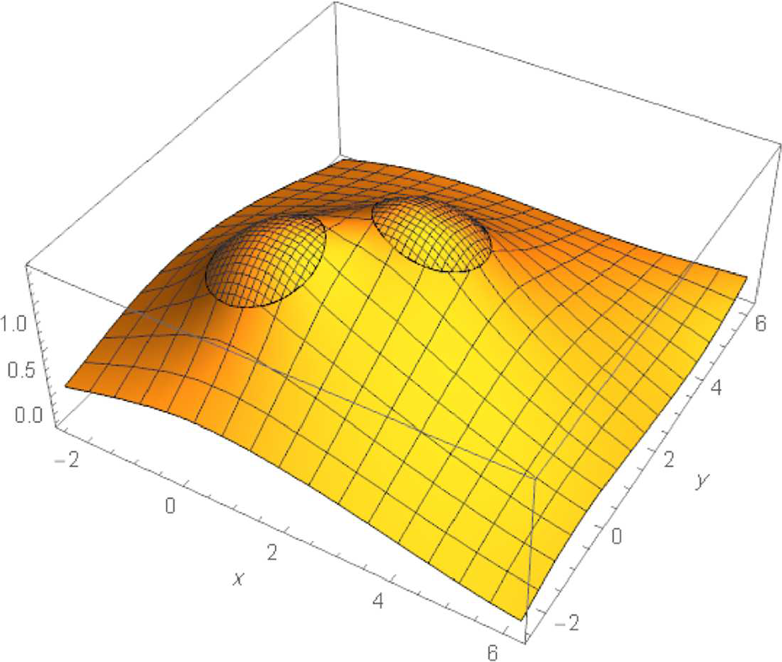
Distribution of the magnetic vector potential in an area including the two cylinders.
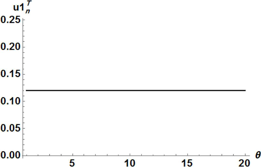
It is seen that the boundary temperatures produce a constant normal displacement of the boundary of the first cylinder of value
5.2. Magnetic field
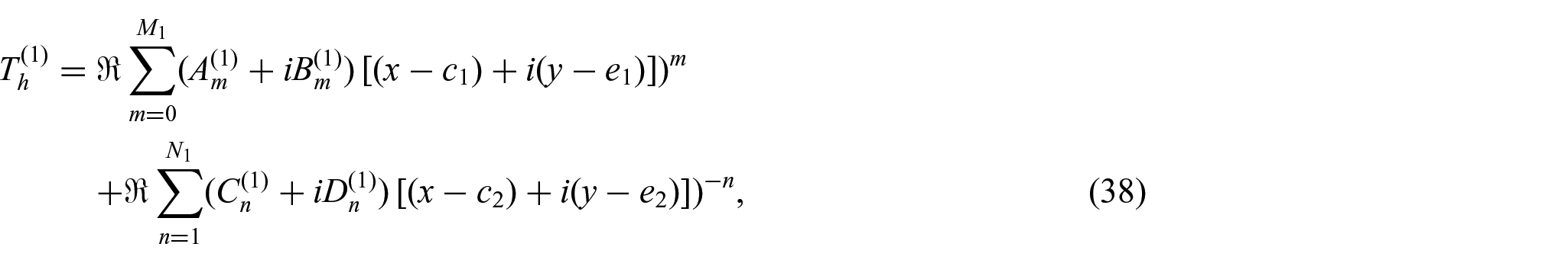
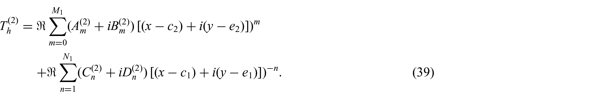
For the harmonic part of the (dimensionless) magnetic vector potential inside the first conductor centered at
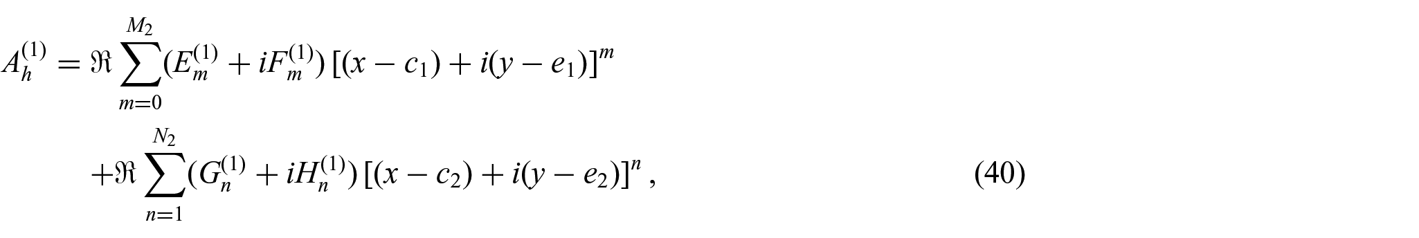
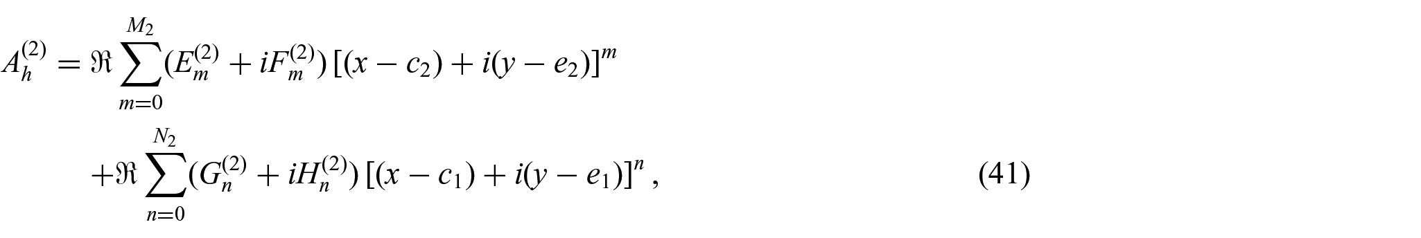
in which only polynomial terms appear. This fact will allow us to easily integrate Poisson’s equation involved in the mechanical part of the problem. A similar expansion is taken inside the second conductor centered at
Numerical experiments have indicated that the errors in satisfying the boundary conditions may be reduced further if one incorporates into the second of expressions (34) additional logarithmic terms centered inside the cylinders, with unknown strengths to be determined together with the coefficients of the expansions. For the present case, the expression for the magnetic vector potential far away from the conductors is taken as

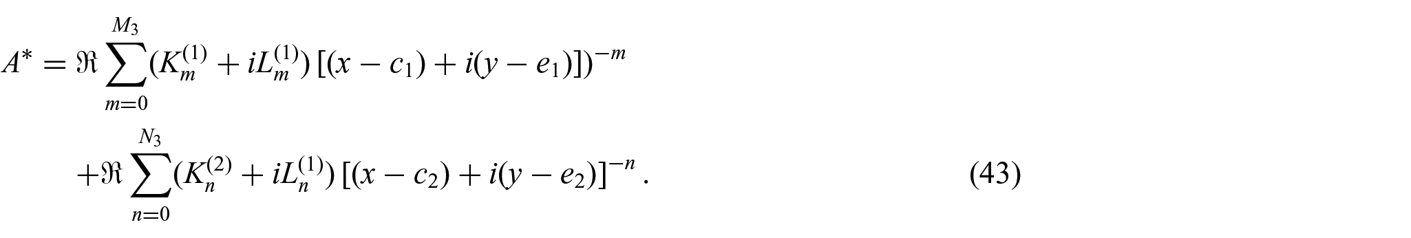
The harmonic part of the magnetic vector potential outside the conductors is represented as
The following results were obtained for the values:

and

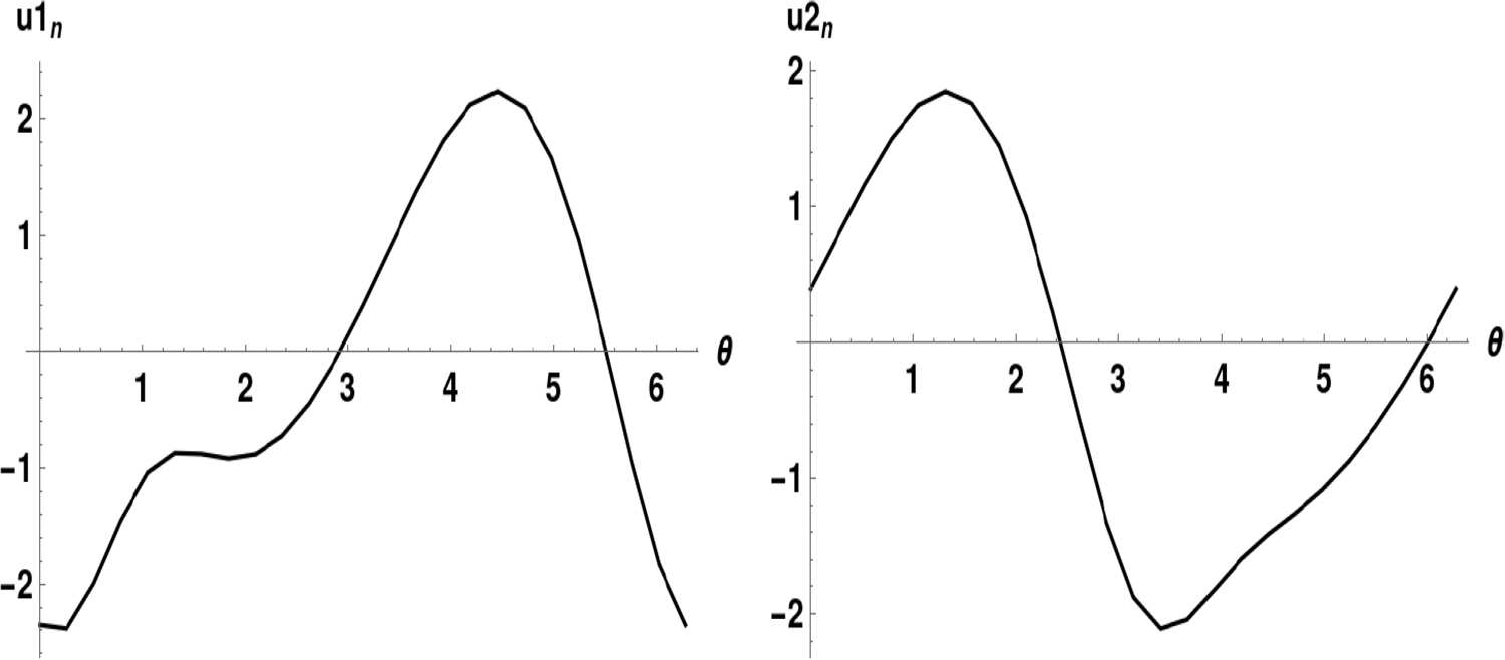
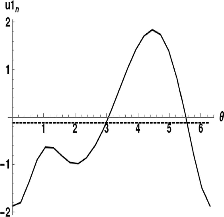
The plots in Figure 6 illustrate the distributions of the boundary components of the magnetic field for the first cylinder, the dashed plots correspond to the case of only one cylinder. Figure 7 indicates that the normal magnetic field is now non-zero as expected, in contrast to the case of only one cylinder. Turning now to the boundary distributions of the magnetic displacements, Figure 8 shows that they are more uniform for the two cylinders, compared with the case of only one cylinder.
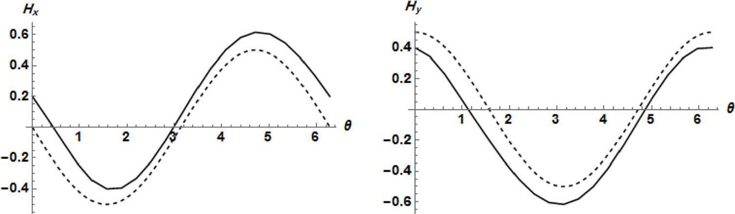
Boundary distributions of the magnetic field components
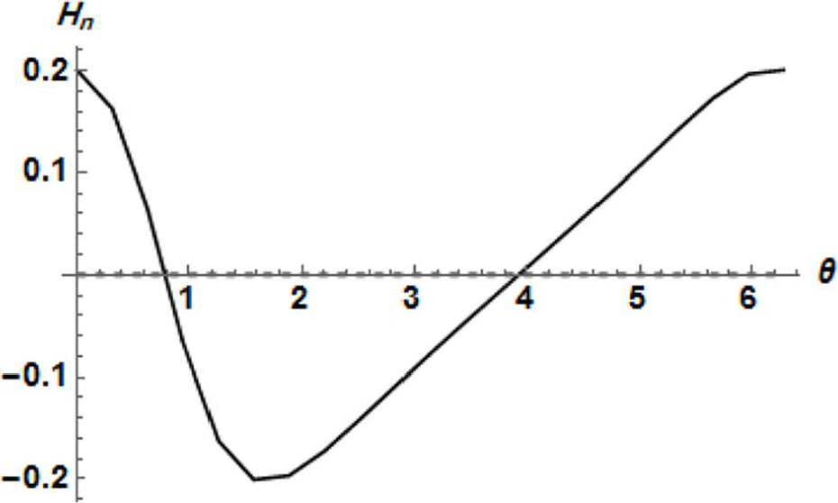
Boundary distribution of the normal magnetic field component
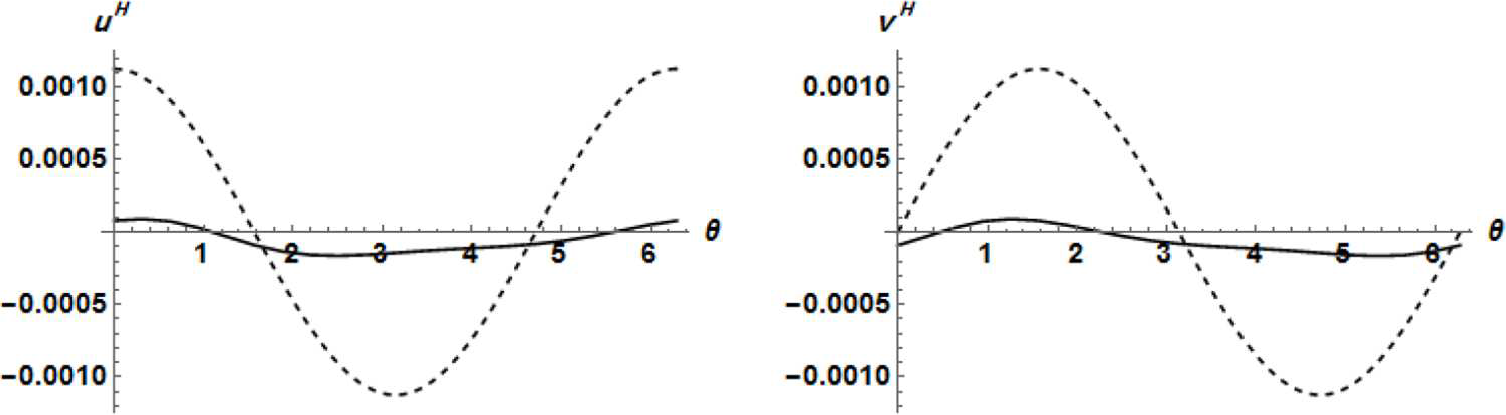
Boundary distributions of the magnetic displacement components
The obtained results may be developed further to find solutions to interesting problems of interactions of steady currents. For example, by letting the value of the radius of one conductor decrease substantially, one can calculate the magnetic field distribution for a long cylindrical conductor placed a distance apart from a long parallel wire.
5.3. Stresses and displacements
The expansions for the functions

Figures 9 and 10 illustrate the distributions of Airy’s stress function and the stress components in the normal cross-section of the first cylinder.
Airy’s stress function for the first cylinder.
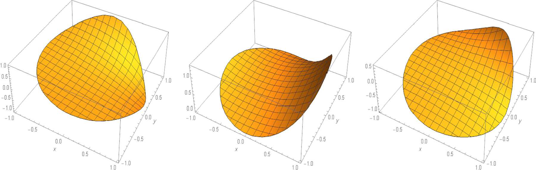
Stress components
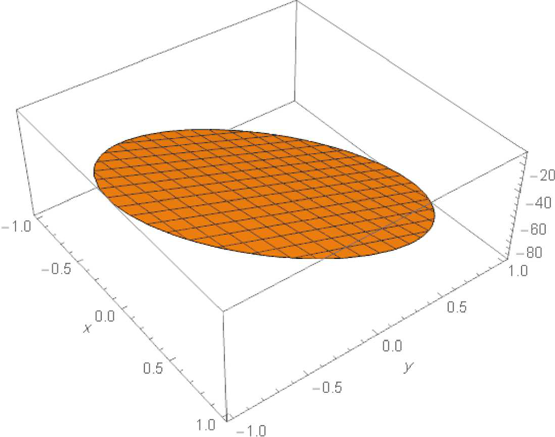
The normal mechanical displacements at the boundaries of the conductors are shown in Figure 11. These may change sign at different portions of the boundaries, a fact that differs completely from the case of a single conductor where the whole boundary acquires a negative normal displacement as in Figure 12.
Boundary normal displacements of the two conductors.
Comparison between the boundary normal displacements of the first conductor in the presence (plain curve) or absence (dashed curve) of the second conductor.
In order to illustrate the effect of relative positions of the conductors, the boundary normal displacement for the first conductor is plotted in Figure 13 for three values of the radius.
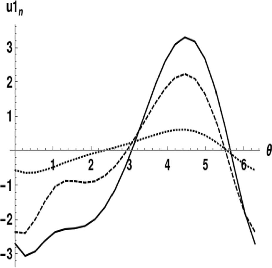
Comparison between the boundary normal displacements of the first conductor for three values of the radii:
6. Conclusions
A method of solution proposed earlier for the plane problem of thermo-magnetoelasticity for one long cylinder carrying a steady uniform electric current has been modified to deal with multiple non-intersecting parallel conductors. The consideration of multiple electrical conductors involves important practical industrial applications, as the conductors are usually found in groups in the electrical power plants and in various technological devices. Comparison of the results with those for a single conductor allows us to elucidate the interaction between conductors, whether in the purely magnetic problem or for the elastic field distribution entering into the mechanical boundary conditions.
The method provides an efficient way to calculate the stresses and the displacements in the elastic conductors. It deals with general geometries of the normal cross-sections, provided these are simply connected, and under various thermal and mechanical conditions. The presence of more than one conductor allows us to enrich the expansions describing the unknown harmonic functions involved in the solution, compared with the case of a single conductor.
The proposed expressions for the magnetic vector potentials inside the conductors provide an efficient tool to solve new problems of interaction of steady currents. As an example, to find the coefficients of self- and mutual inductance of a system of straight long conductors, or to calculate the magnetic field due to a long conductor placed a distance apart from a parallel long wire.
The presented application concerns two equal long cylinders of the same material with circular normal cross-section and carrying currents of the same intensity and same sense, subjected to the Robin thermal condition. The distribution of magnetic vector potential in space and those of stress inside the conductors were obtained with very good accuracy in satisfying the boundary conditions. The boundary magnetic field components and the boundary normal mechanical displacement were plotted and discussed. Some aspects of the interaction of the two conductors were elucidated. Cases with more than two conductors can be treated equally well.
Footnotes
Appendix A
The temperature distribution generates in each conductor “temperature displacements,” which will go into the expressions for the mechanical displacement components. These are expressed as (cf. [5, 7])
where
Appendix B
Similar to the thermal problem, the magnetic field distribution inside each of the conductors generates a distribution of “magnetic displacements”, which are part of the mechanical displacement components. They are given by [5, 7]:
where
and
Again, the integrations in (45) are path independent for any of the conductors.
Funding
This project was supported financially by the Academy of Scientific Research and Technology (ASRT), Egypt (grant number 6446).