This paper investigates the frictional contact problem of a layer indented by a rigid punch within the framework of the couple stress elasticity. It is assumed that the layer is homogeneous, isotropic, and fully bonded to a rigid substrate. The mixed-boundary value problem is converted using Fourier transform into a singular integral equation in which the unknown is the contact pressure between the layer and the punch. The integral equation is further derived for the flat and cylindrical punch case profiles, normalized and then solved numerically using the Gauss–Jacobi integration formula. The obtained results are first validated based on those published for the case of a frictionless contact problem of a half-plane indented by a rigid punch and solved within the context of couple stress theory. An extensive parametric study is then conducted to investigate the effect of several parameters on the contact stresses for the both the flat and cylindrical punch profiles. These parameters include the characteristic material length, the layer height, the friction coefficient, the indentation load, and the shear modulus.
Nanoindentation testing has been a widely used method to characterize material properties at the micro- and nanoscales, which include elastic modulus, hardness, and yield strength. This experimental technique has been popular because it is inexpensive, easy to conduct, non-destructive, and accurate. It utilizes indenters such as cylindrical indenter, Berkovich pyramid indenter, Rockwell conical indenter, and Brinell spherical indenter [1,2]. Nanoindentation experiments have shown that as the specimen dimensions reduce to the micro- and nanoscales, the mechanical properties increase drastically indicating a strong size dependency [3–7].
In an indentation experiment, it was shown that the response of the material during unloading is largely elastic and as a result the theory of elastic contact may be employed to estimate the elastic modulus from a load-displacement indentation data [8]. As the specimen dimensions in an indentation test are reduced, length scale effects become more dominant and classical continuum mechanics cannot predict these effects because it does not possess any intrinsic length scale parameters. To study size effects in this experiment, two different methods have been employed, namely, material microstructure discrete modeling approach and higher-order size-dependent continuum mechanics approach [9]. The first one is computationally expensive because it requires detailed modeling of the material microstructure. The second approach consists of smearing the material microstructure by expanding classical continuum mechanics by an additional characteristic length scale to extend its applicability to micro- and nano-levels. To this end, several higher-order size-dependent continuum mechanics theories have been put forward during the last few decades to model the microstructure-dependent size-dependent effects on the elastic properties of the material. These theories include the micropolar theory, the couple stress theory (CST), and the strain gradient theory.
One of the most widely used size-dependent theories is the CST which has been also referred to as Cosserat theory [10,11]. The CST is considered to be the simplest gradient theory in which the rotation gradient is introduced as a new deformation measure. CST is different from the classical theory in several aspects. First, the strain energy is a function of not only the infinitesimal strains but also the strain gradients (i.e., rotation gradients). In addition, the constitutive relations involve two new additional elastic constants one of which is a function of the so-called length scale material parameter that can capture size effects. When the length scale parameter goes to zero, CST degenerates to the classical theory of elasticity.
The CST has been widely applied to obtain the response of nanostructures including beams and plates but with rather limited applications to nanoindentation problems. In what follows is a brief summary of a number of these studies which employed the CST. Zisis et al. [12] studied the frictionless contact problem of an isotropic elastic half-plane loaded by a rigid stamp of an arbitrary profile. Gourgiotis et al. [9] investigated the indentation of a tilted flat punch on a half-plane using the method of singular integral equations and studied among others the effect of material length scale on the contact stresses. Gourgiotis and Zisis [13] derived a two-dimensional Green’s function and then solved the contact problems of a half-plane loaded by a rigid microindenter. In another study, Zisis [14] extended the so-called Burmister’s problem to study the response of a microstructured layer bonded to a rigid substrate under the action of a normal load. In a similar study, Zisis [15] investigated the anti-plane response of a microstructured half-plane and layer of finite thickness bonded to a rigid substrate and subjected to a tangential point load on the surface. Karuriya and Bhandakkar [16] considered the contact problem of a layer of finite thickness under the action of an indentor of an arbitrary profile. Song et al. studied the frictional contact problem of a half-plane [17] and the frictionless contact problem of coated semi-infinite medium [18]. Wang et al. [19] investigated the partial slip contact problem of a half-plane subjected to a rigid cylindrical punch. In another study, the same authors developed a three-dimensional analytical model to study the contact of a half-plane with a rigid sphere [20]. Gourgiotis et al. [21] reconsidered the classical three-dimensional Hertz contact problem within the context of the CST.
Although there are limited number of studies related to the frictionless contact problem within the context of the CST, the frictional case is very rare. To the best of authors’ knowledge, there is no study in the literature that considers the frictional effect on the contact problem of finite thickness layer using CST. To fill this gap in the literature, the frictional contact problem of a finite thickness layer indented by a rigid cylindrical punch is considered within the framework of CST. The proposed problem in addition to other published contact problems employing the CST is quite important in understanding several nanotechology applications such as nanoindentation tests characterized by small-scale contact. The remainder of this paper is organized as follows. Section 2 describes the problem under consideration and the initial solution methodology using Fourier integral transform. The application of the boundary conditions and the derivation of the singular integral equation are detailed in Section 3. The numerical solution for solving the singular integral equation is summarized in Section 4. Results are presented and discussed in Section 5. Finally, a summary of this study in addition to concluding remarks is provided in Section 6.
2. Formulation and basic equations in couple stress elasticity
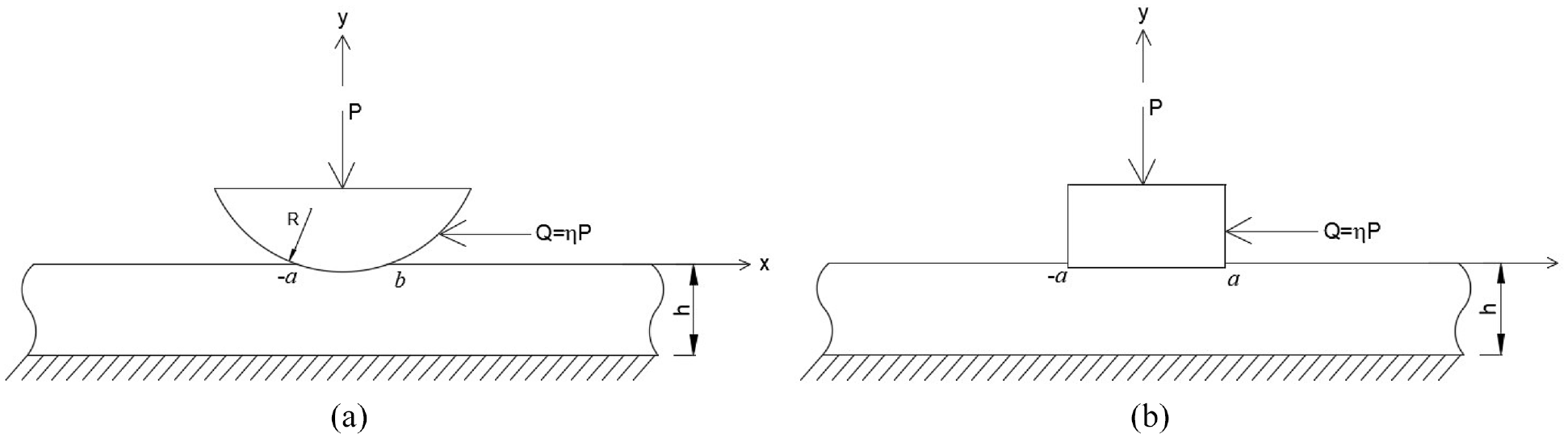
Consider the plane strain contact problem of a layer indented by a flat or a circular rigid punch as shown, respectively, in Figure 1(a) and (b). The homogeneous and isotropic layer of thickness is fully bonded to a rigid substrate. The rigid punch is subjected to a normal load and tangential load . The proposed formulation is similar to the one adopted by Zisis et al. [12]. The considered problem is described in the cartesian coordinate system as depicted in the figure. The geometric equations in the framework of coupled stress elasticity can be written as follows:
where are the displacement components, are the strain components, is the rotation vector, are the curvature components. Ignoring the body forces, the equations of equilibrium are given by
where and are the stress and couple stress components, respectively. The constitutive equations can be expressed as follows:
and
Geometry of the contact problem: (a) Flat punch case; (b) Cylindrical punch case.
Based on the previous equations, the following stress and couple stress equations of compatibility can be obtained:
Using the Mindlin’s stress functions [10], the solution of equation (2) can be expressed as follows:
and
where and are arbitrary but sufficiently smooth stress functions. Substituting equations (8) and (9) into equation (7) yields following partial differential equations (PDEs):
which are then decoupled as follows:
Substituting equation (8) into equation (3) and considering equation (1a) yields the displacement field which can be written in terms of Mindlin’s stress functions as
The PDEs can be converted into ordinary differential equations (ODEs) using Fourier integral transform technique. The Fourier transform and its inverse are defined as follows:
where is the imaginary unit. Applying the Fourier transform to equation (11) leads to the following ODEs:
Similarly, the transformed stress, couple stress, and displacement expressions can be obtained as follows:
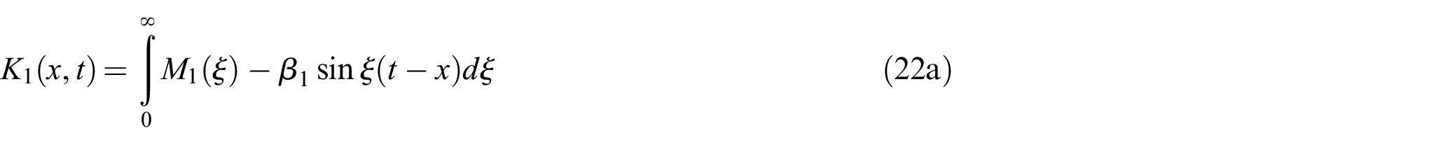
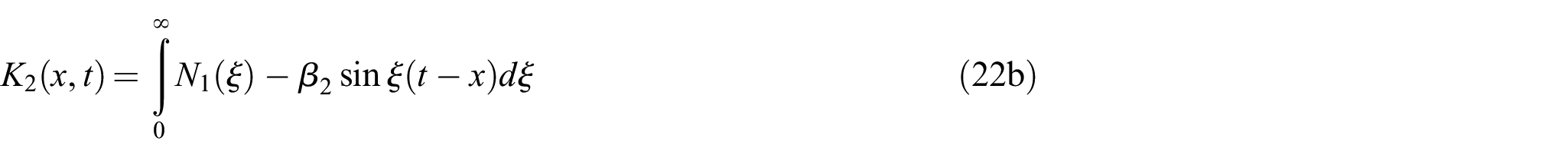
The solution of the governing equations (14a) and (14b) can be written as
where . and are coefficients to be determined from the boundary and compatibility conditions.
3. Boundary conditions and singular integral equation
The plane contact problem outlined above must be solved under the following boundary conditions:
where is the friction coefficient and is the contact stress on the contact region . Since the layer is fixed at the bottom at (see Figure 1), the rotation can also be considered as a boundary condition instead of equation (17f) [16]. However, is not used here as it is inconsistent with the corresponding classical elasticity solution which leads to . Hence, instead of the rotation condition , the couple stress condition is employed in this formulation such that the couple stress elasticity solution converges to the classical elasticity solution in the limiting case when .
To solve for the eight unknowns of the problem, and , the above six boundary conditions are employed in addition to the two compatibility equations (10) which can be written as follows:
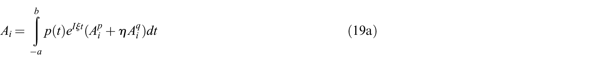
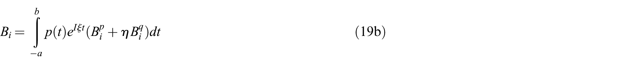
Using the boundary conditions equation (17) and compatibility equations (18), the unknown coefficients and can be determined in terms of the contact stress as follows:
To solve for the contact stress , the following mixed-boundary condition can be used:
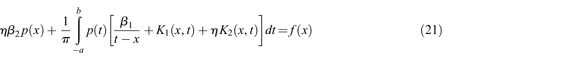
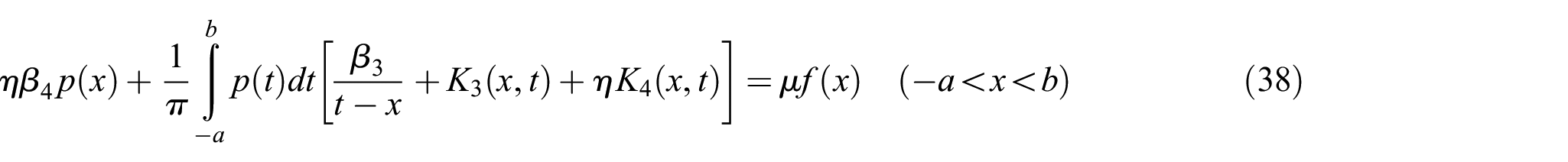
where is the derivative of the punch shape function. Substituting the unknowns and into the above equation yields the following second-kind singular integral equation which can be written as
where
in which
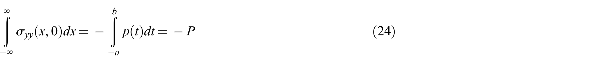
In the above equations, the expressions of and are lengthy and do not depend on the friction coefficient . To complete the solution of equation (21), the following equilibrium condition is required:
4. Numerical solution of the singular integral equation
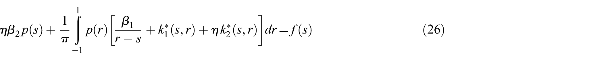
Similarly, the equilibrium condition equation (24) can be written in the normalized form as follows:
The solution of the singular integral equation (26) can be written as
where is the weight function of associated with the Jacobi polynomial which can be expressed as
in which and are the so-called strength singularities evaluated using the following relations [22]
where and are arbitrary integers and must be determined using the inequality for the index.
Using Gauss–Jacobi quadrature formula [22], the integral equation (26) can be converted to the algebraic equation system as follows:
where is the number of retained terms in the Gauss–Jacobi quadrature formula [22], and are the roots of the Jacobi polynomial, and is the weighing constant which are all given by
Similarly, the equilibrium condition (28) becomes
4.1. Solution of the cylindrical punch case
For the cylindrical punch case (Figure 1(a)), the derivative of the punch can be written as
where is the punch radius. As the contact stress vanishes at the ends of the contact region, the index of the integral equation (21) is [22]. Note that there are equations to determine the unknowns in equation (32) for . The extra equation is extracted from equation (32) and used to determine the unknowns a and b with the equilibrium condition (34). Thus, equations (32) and (34) provide algebraic equations to be solved for unknowns which are the contact widths and and . The system of equations are linear in terms of , but highly nonlinear in terms of and . Thus, an iterative scheme must be adopted to solve for the unknowns.
4.2. Solution of the flat punch case
For the flat punch case (Figure 1(b)), and since the shape function of the flat punch is constant the derivative of the punch function is
Since there is a sharp edge at the ends of the rigid flat punch, the index of the integral equation (21) is . Equations (32) and (34) provide equations with unknowns which are .
5. Classical solution of the contact problem
For the classical solution, the displacement and stress components in the layer can be written as follows [23]:
Applying the boundary conditions equations (17)(a-d) and (20) yields the following singular integral equation:
where
6. Results and discussion
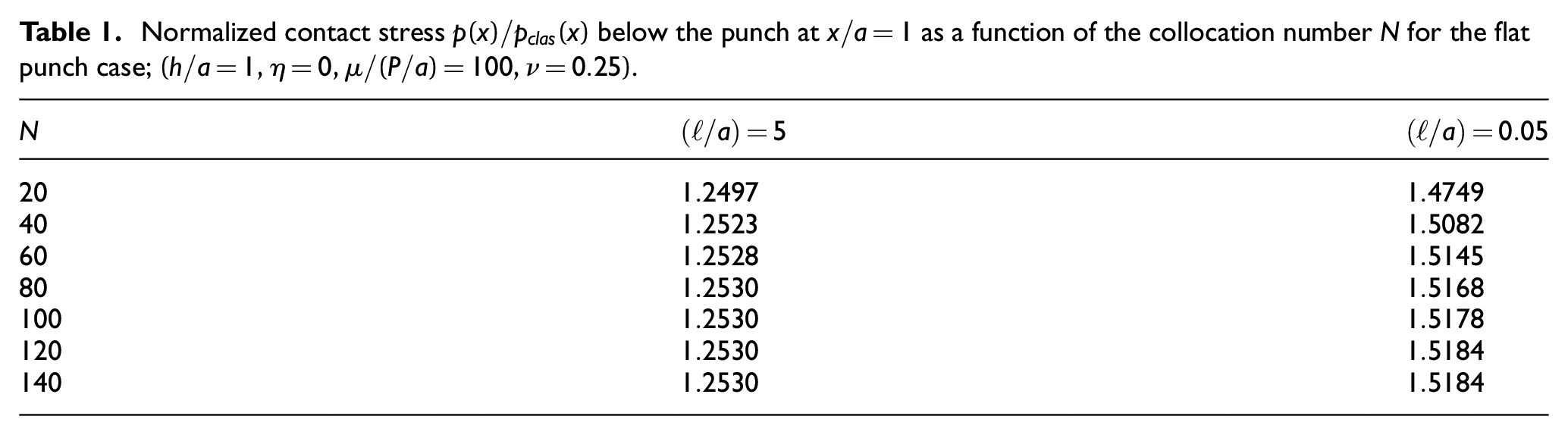
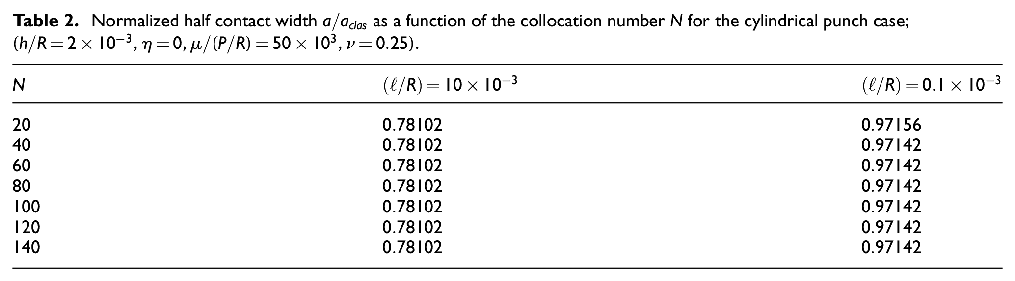
The geometry and the coordinate system of the investigated contact problem are illustrated in Figure 1(a) and (b) for the flat and cylindrical punch profiles, respectively. A convergence study is first conducted to study the influence of the collocation number appearing in the discretized integral and equilibrium equations (32) and (34). The convergence is similar to the one performed by Zisis et al. [12]. Table 1 reports the normalized contact stress obtained for the flat punch case for different values of the collocation number and for limiting values of the normalized characteristic length 0.05 and 1. According to this table, convergence is reached at about and hence this value is used in the remainder of the analysis for the flat punch case. Similarly, Table 2 tabulates the normalized half contact width for the cylindrical punch case for different values of the collocation number and for limiting values of the normalized characteristic length and . Based on this table, convergence is achieved at around and thus this value is utilized in the remainder of the analysis for the cylindrical punch case.
Normalized contact stress below the punch at as a function of the collocation number for the flat punch case; .
Normalized half contact width as a function of the collocation number for the cylindrical punch case; .
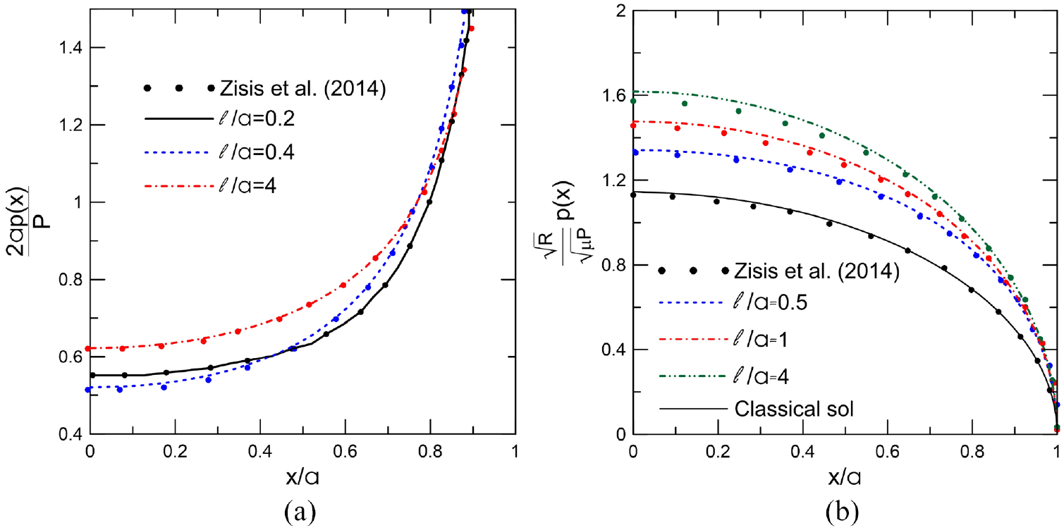
The results obtained from the present formulation are next validated based on the those published by Zisis et al. [12] for the case of a frictionless contact problem of a half-plane indented by a rigid punch and solved within the framework of CST. Such a comparison is shown in Figure 2(a) and (b) for the flat and cylindrical punch profiles, respectively. Both figures indicate an excellent agreement between the obtained and published results for the classical solution as well as for different values of the length scale parameter associated with the CST.
Comparison of the obtained results with those of Zisis et al. [12]; (a) Flat punch case; (b) Cylindrical punch case.
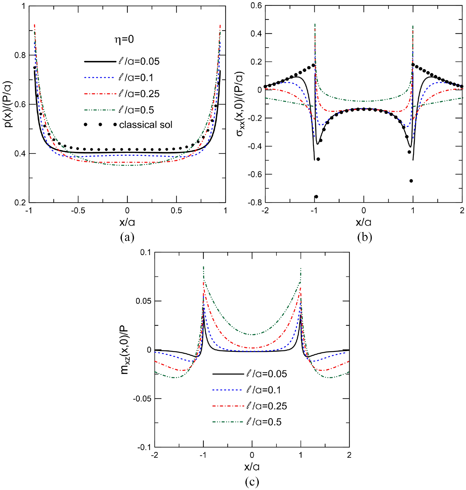
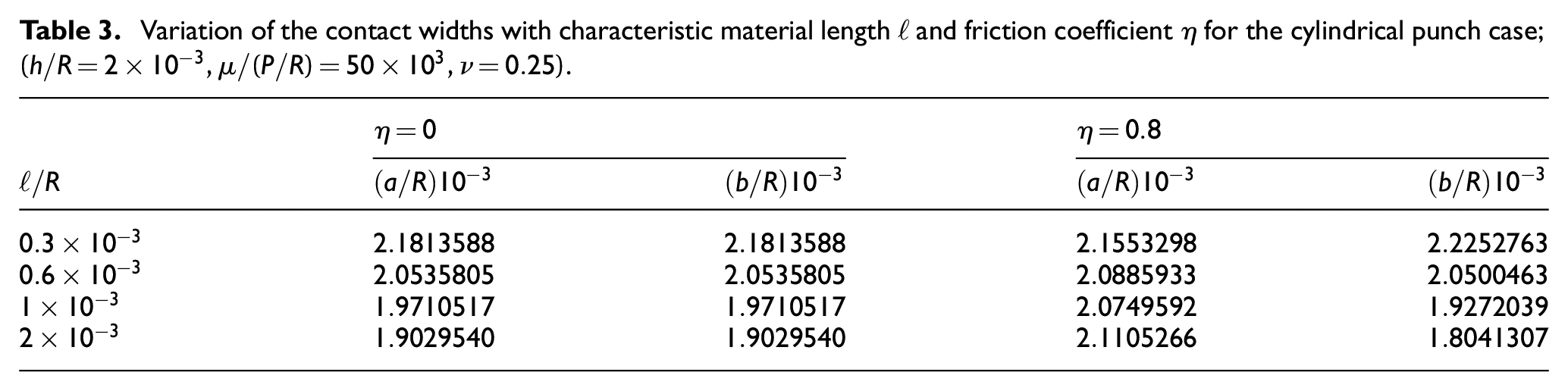
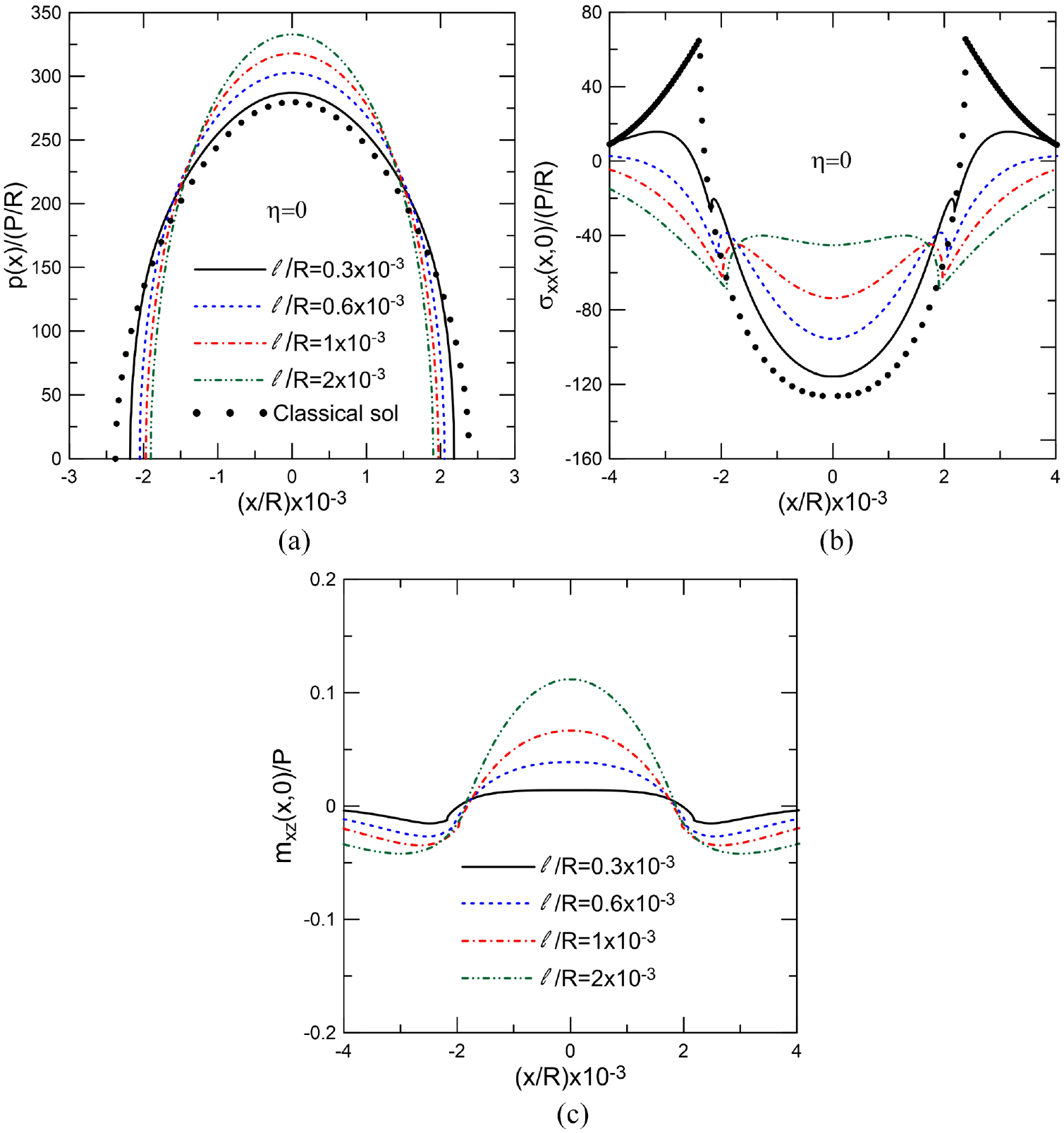
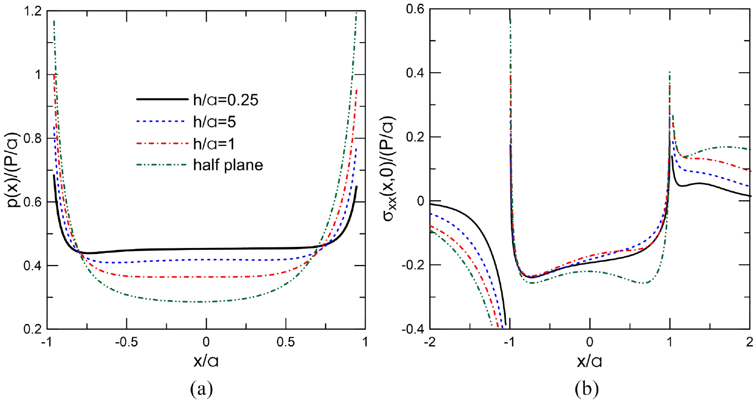
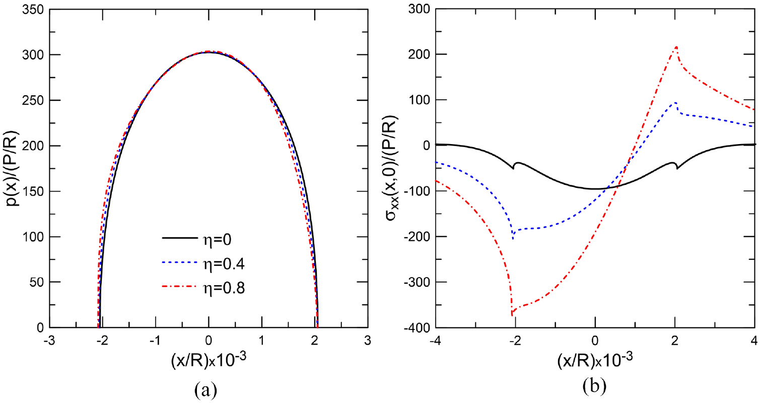
The remainder of this section is devoted for the parametric study whose purpose is to investigate the effect of several parameters on the contact pressure and the stress , for both the flat and cylindrical punch profiles. These parameters include the characteristic material length , the layer height , the friction coefficient , the indentation load , and the shear modulus . Figure 3(a) and (b) shows the effect of the characteristic material length on the contact stresses, respectively, for the case of the flat punch. The following parameters are used in this analysis: for the case of the flat punch and for the case of the cylindrical punch. The curve referred to as the classical solution has a zero value characteristic length. Both figures indicate that the contact and the in-plane stresses are singular at the two ends of the flat punch and their distributions are qualitatively similar. Furthermore, increasing the value of has a tendency to increase the maximum contact stresses but rather decrease the in-plane stresses all over the contact region. As the value of becomes smaller, the distribution of the contact and in-plane stresses get closer to the classical solution. It can also be observed that the stress becomes negative not only inside the contact area but outside of it. To explain this, a plot of the stress , shown in Figure 3(c), indicates that this stress is making more negative outside the contact region and less negative inside the contact region for increasing values of the characteristic material length . It is worth noting that for the classical solution corresponding to a zero value of the characteristic material length. Table 3 illustrates the variation of the contact widths with the characteristic material length and the friction coefficient for the cylindrical punch case. The effect of the characteristic material length on the contact and the in-plane stresses, respectively, for the case of the circular punch is depicted in Figure 4(a) and (b). The effect is qualitatively similar to the case of the flat punch except there are no singularities and increasing the value of results in a decrease of the contact region associated with an increase of the maximum contact stress. It is obvious that the classical and couple stress solutions approach each other as the characteristic material length decreases. Moreover, similar to the flat punch, the stress becomes negative not only inside the contact area but outside of it. To this end, a plot of the stress , illustrated in Figure 4(c), shows that this stress is making more negative outside the contact region and less negative inside the contact region for increasing values of the characteristic material length .
Effect of the characteristic material length on (a) the contact stress , (b) the stress , and (c) the couple stress for the flat punch case; .
Variation of the contact widths with characteristic material length and friction coefficient for the cylindrical punch case; .
Effect of the characteristic material length on (a) the contact stress , (b) the stress , and (c) the couple stress for the cylindrical punch case; .
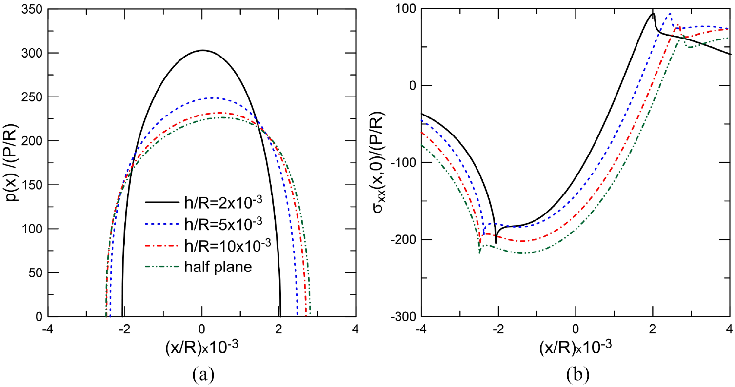
Figure 5(a) and (b) illustrate the effect of the layer height on the contact and the in-plane stresses, respectively, for the case of the flat punch. The results are obtained by fixing the values of the following parameters: , . It is clear that the contact and the in-plane stresses are singular at the ends of the punch and increasing the layer thickness results in an increase of the contact stresses. Moreover, the rate of increase of the in-plane stresses is more pronounced in the leading edge as compared with the trailing edge of the punch. The effect of the layer height on the contact and the in-plane stresses, respectively, for the case of the circular punch is demonstrated in Figure 6(a) and (b). It can be seen that the behavior is quite different from the flat punch case in that increasing the layer height has a tendency to decrease the contact and the in-plane stresses at the expense of widening the contact region.
Effect of the layer height on (a) the contact stress and (b) the stress for the flat punch case;
Effect of the layer height on (a) the contact stress and (b) the stress for the cylindrical punch case; .
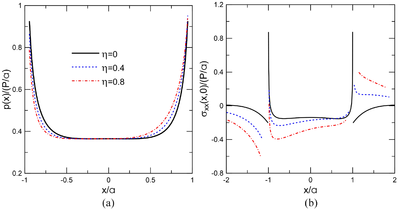
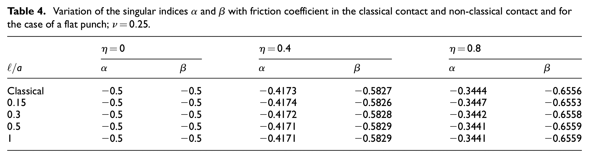
Figure 7(a) and (b) depicts the influence of the friction coefficient on the contact and the in-plane stresses, respectively, for the case of the flat punch. The following parameters are used in this analysis: . Both figures indicate that the contact and the in-plane stresses are singular at the two ends of the flat punch. Furthermore, increasing the value of has a tendency to keep the maximum contact stresses more or less constant, but an increase of the contact stresses in the leading edge and a decrease of these stresses at the trailing edge are observed. This can be explained by the values of the singular indices and where an increase of results in a decrease and increase of and , respectively, as depicted in Table 4. The effect of friction coefficient on the contact and the in-plane stresses for the case of the circular punch is illustrated, respectively, in Figure 8(a) and (b). The effect is somewhat different from the flat punch case. First, increasing the value of has almost an insignificant effect on the contact stresses but affects largely the in-plane stresses. In fact, these stresses increase in tension in the leading edge and increase in compression in the trailing edge. This can be explained by observing the strength singularities and which experience, respectively, a decrease and an increase upon augmenting the value of the friction coefficient , as depicted in Table 5.
Effect of the friction coefficient on (a) the contact stress and (b) the stress for the flat punch case; .
Variation of the singular indices and with friction coefficient in the classical contact and non-classical contact and for the case of a flat punch; .
Classical
−0.5
−0.5
−0.4173
−0.5827
−0.3444
−0.6556
−0.5
−0.5
−0.4174
−0.5826
−0.3447
−0.6553
−0.5
−0.5
−0.4172
−0.5828
−0.3442
−0.6558
−0.5
−0.5
−0.4171
−0.5829
−0.3441
−0.6559
−0.5
−0.5
−0.4171
−0.5829
−0.3441
−0.6559
Effect of the friction coefficient on (a) the contact stress and (b) the stress for the cylindrical punch case; .
Variation of the singular indices and with friction coefficient in the classical contact and non-classical contact and for the case of a cylindrical punch; .
Classical
0.5
0.5
0.4578
0.5422
0.4171
0.5829
0.5
0.5
0.5738
0.4262
0.6405
0.3595
0.5
0.5
0.5805
0.4195
0.6519
0.3481
0.5
0.5
0.5821
0.4179
0.6545
0.3455
0.5
0.5
0.5827
0.4173
0.6556
0.3444
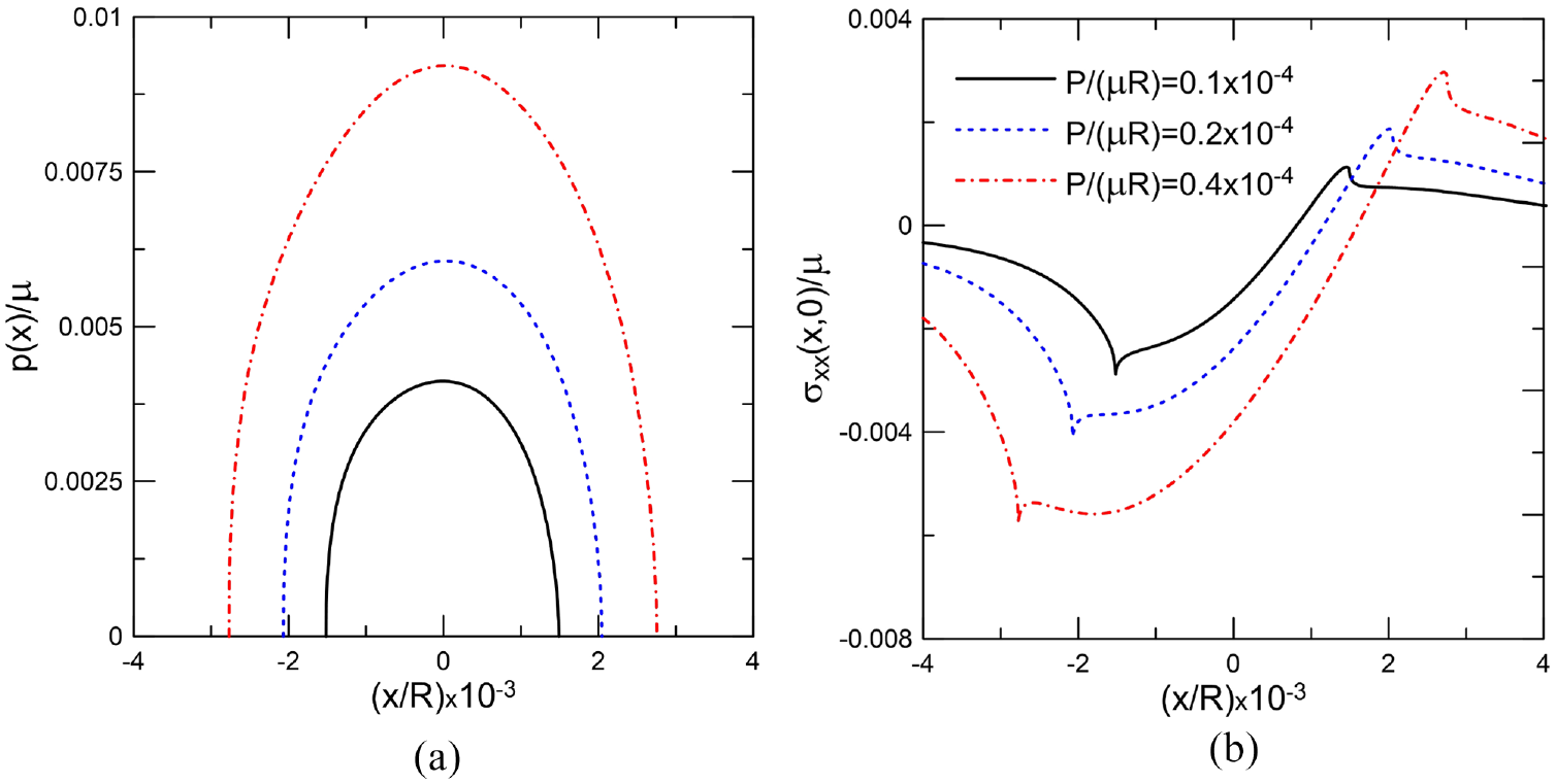
The influence of the indentation load on the contact and the in-plane stresses for the case of a flat punch will not be investigated because the contact problem is linear. The results are obtained by fixing the values of the following parameters: . Figure 9(a) and (b) depicts the effect of the indentation load on the contact and the in-plane stresses for the case of the circular punch, respectively. It can be observed that increasing the indentation load results in an increase in the contact and the in-plane stresses at the expense of enlarging the contact region.
Effect of the indentation load on (a) the contact stress and (b) the stress for the cylindrical punch case; .
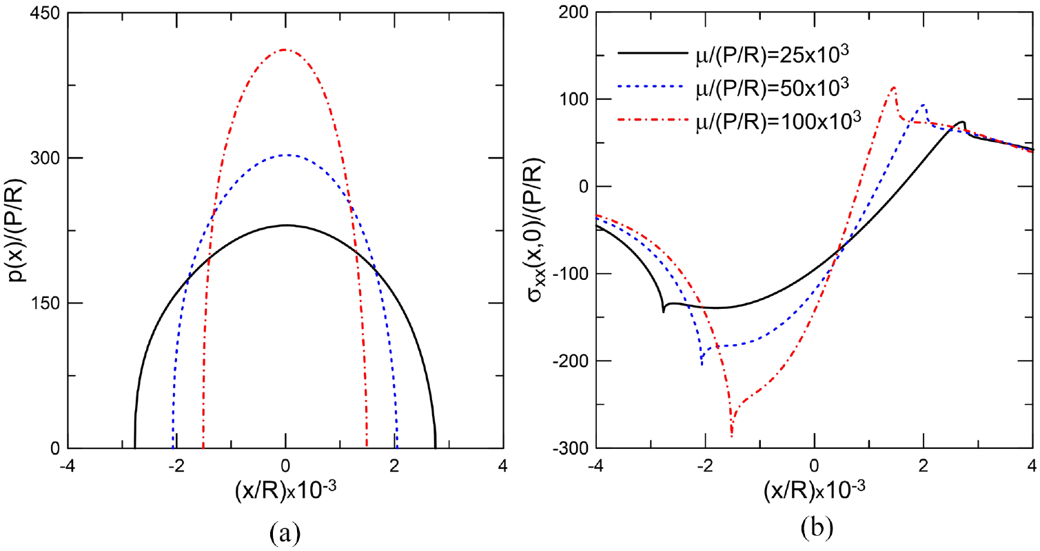
Finally, the effect of the shear modulus on the contact and the in-plane stresses is only investigated for the cylindrical punch case because the flat punch results are independent of the shear modulus because the right-hand side of the singular integral equation (38) becomes zero for this type of profile . Figure 10(a) and (b) illustrates the influence of the shear modulus on the contact and the in-plane stresses for the case of a circular punch, respectively. It can be concluded that increasing the shear modulus results in an increase in the maximum contact stresses at the expense of shrinking the contact area.
Effect of the shear modulus on (a) the contact stress and (b) the stress for the cylindrical punch case; .
7. Conclusion
The frictional contact problem between a layer and a rigid punch within the framework of Couple Stress Elasticity is considered in this paper. The layer was assumed to be homogeneous and isotropic and fully bonded to a rigid substrate. Using standard Fourier transform, the plane elasticity equations along with the appropriate boundary conditions were employed to convert the mixed-boundary value problem into a singular integral equation in which the unknown is the contact pressure between the layer and the punch. The singular integral equation was further derived for the flat and punch case profiles, normalized and then solved numerically using the Gauss–Jacobi integration formula. The obtained results were first validated based on those published for the case of a frictionless contact problem of a half-plane indented by a rigid punch and solved within the framework of CST. The following conclusions can be drawn from this study:
The contact stresses increase but in-plane stresses decrease as the characteristic material length gets larger.
As the layer height increases, the contact region becomes larger resulting in a decrease of the contact stresses for the cylindrical punch case.
For the cylindrical punch case, the contact stresses are almost insensitive to the change of the friction coefficient, but the in-plane stresses increase in tension in the leading edge and increase in compression in the trailing edge as the friction coefficient increases.
The contact and in-plane stresses increase as the indentation load becomes larger for both cylindrical and flat punch cases.
The contact and in-plane stresses are insensitive to the change of shear modulus of the layer for the flat punch case. However, they increase as the layer becomes stiffer for the cylindrical punch case.
Footnotes
Acknowledgements
The authors are thankful for the assistance of Mrs. Hedia Layouni El-Borgi in typesetting the Latex document.
Funding
The author(s) disclosed receipt of the following financial support for the research, authorship, and/or publication of this article: The second author is grateful for the funding provided by Texas A&M University at Qatar. The publication of this article was funded by Qatar National Library.
ORCID iDs
Isa Çömez
Sami El-Borgi
References
1.
JohnsonKL. Contact mechanics. Cambridge: Cambridge University Press, 1987.
FleckNAMullerGMAshbyMF, et al. Strain gradient plasticity: theory and experiment. Acta Metal Mater1994; 42(2): 475–487.
4.
ZhongL. Deformation behavior and microstructure effect in 2124Al/SiCp composite. J Comp Mater2000; 34(2): 101–115.
5.
HuberNNixWDGaoH. Identification of elastic-plastic material parameters from pyramidal indentation of thin films. Proc Royal Soc London—Series A: Math, Phys Sci2002; 458(2023): 1593–1620.
6.
LiuDHeYTangX, et al. Size effects in the torsion of microscale copper wires: experiment and analysis. Script Mater2012; 66(6): 406–409.
7.
KathavateVSKumarBPSinghI, et al. Analysis of indentation size effect (ISE) in nanoindentation hardness in polycrystalline PMN-PT piezoceramics with different domain configurations. Ceramics International2021; 47(9): 11870–11877.
8.
PharrGMOliverWCBrotzenFR. On the generality of the relationship among contact stiffness, contact area, and elastic modulus during indentation. J Mater Res1992; 7(3): 613–617.
9.
GourgiotisPAZisisTBaxevanakisKP. Analysis of the tilted flat punch in couple-stress elasticity. Int J Solids Struct2016; 85: 34–43.
10.
MindlinRD. Influence of couple-stresses on stress concentrations. Exp Mech1963; 3(1): 1–7.
11.
ToupinRA. Theories of elasticity with couple-stress. Arch Ration Mech Anal1964; 17(2): 85–112.
12.
ZisisTGourgiotisPABaxevanakisKP, et al. Some basic contact problems in couple stress elasticity. Int J Solids Struct2014; 51(11–12): 2084–2095.
13.
GourgiotisPZisisT. Two-dimensional indentation of microstructured solids characterized by couple-stress elasticity. J Strain Anal Eng Design2016; 51(4): 318–331.
14.
ZisisT. Burmister’s problem extended to a microstructured layer. J Mech Mater Struct2018; 13(2): 203–223.
15.
ZisisT. Anti-plane loading of microstructured materials in the context of couple stress theory of elasticity: half-planes and layers. Arch Appl Mech2018; 88(1): 97–110.
16.
KaruriyaANBhandakkarTK. Plane strain indentation on finite thickness bonded layer in couple stress elasticity. Int J Solids Struct2017; 108: 275–288.
17.
SongH-XKeL-LWangY-S. Sliding frictional contact analysis of an elastic solid with couple stresses. Int J Mech Sci2017; 133: 804–816.
18.
SongHKeL-LWangY-S, et al. Two-dimensional frictionless contact of a coated half-plane based on couple stress theory. Int J Appl Mech2018; 10(5): 1850049.
19.
WangYShenHZhangX, et al. Semi-analytical study of microscopic two-dimensional partial slip contact problem within the framework of couple stress elasticity: cylindrical indenter. Int J Solids Struct2018; 138: 76–86.
20.
WangYZhangXShenH, et al. Three-dimensional contact analysis with couple stress elasticity. Int J Mech Sci2019; 153: 369–379.
21.
GourgiotisPAZisisTGiannakopoulosAE, et al. The Hertz contact problem in couple-stress elasticity. Int J Solids Struct2019; 168: 228–237.
22.
ErdoganFGuptaGDCookTS. Numerical solution of singular integral equations. In: SihGC (ed.) Methods of analysis and solutions of crack problems. Berlin: Springer, 1973, pp. 368–425.
23.
ÇömezIErdölR. Frictional contact problem of a rigid stamp and an elastic layer bonded to a homogeneous substrate. Arch Appl Mech2013; 83(1): 15–24.