Engineered fibers such as azobenzene—a photoresponsive material—change their stress free or natural reference length in response to ultraviolet (UV) light. This work focuses on the mechanics of a plane annular membrane formed from a homogeneous incompressible nonlinear elastic material reinforced by an axisymmetric distribution of activated fibers lying in a plane parallel to the mid-surface. The lengths of these fibers can be triggered to change by non-mechanical influences such as temperature change or radiation from an UV light source. Each fiber has the shape of a plane spiral curve that extends from the inner to the outer radius. The membrane is attached to a rigid circular disc at the inner boundary. The outer boundary can have a prescribed radial stretch. A new constitutive model for the UV-activated fiber-reinforced medium is developed. Boundary value problems that combine twist with radial expansion are formulated and solved as a system of ordinary differential equations. Corresponding finite element (FE) models are also developed. Results show that the contraction of the spiral fibers will lead to a shape change, a shearing deformation in the radial-circumferential plane, and a distribution of shear stresses within the membrane. The resulting shear deformation may cause a principal stress to become negative indicating wrinkling. The shearing deformation disappears in the special cases of radial and circumferential fiber distributions while negative principal stresses might still present. We consider conditions where wrinkling may be avoided by imposing a radial stretch. We also investigate the regimes of instability due to the compressive stress in the membrane using FE methods. Such understanding is critical to multiple applications including designing soft robotic devices that can be actuated by active fibers, biomechanical modeling of biological phenomena (e.g., vasoconstriction and vasodilation in blood vessels, the peristalsis motion in urinary and gastrointestinal tract systems), and complex deformation in muscular hydrostats of animals.
A variety of biological fiber-reinforced structures employ the activation of muscle fibers to generate complex motion and deformation. For example, the peristalsis motion in ureters and intestines is driven by circular and longitudinal muscle contraction [1–3]. Muscular hydrostats in animals (e.g., elephant trunks and octopus arms) can exhibit various modes of deformations such as bending and twisting [4–6]. Such ubiquitous presence of activated fibers in nature has motivated a large body of work from interdisciplinary fields of engineering and material science to develop and design bio-inspired materials and structures where non-mechanical stimuli are used for activation [5–10].
Stimuli-sensitive polymers [7] are a new class of materials with very interesting properties. They respond to specific external non-mechanical changes by altering properties such as shape or color. One particular sub-class consists of photoresponsive polymers that can convert light energy directly into mechanical work [8]. One such material is azobenzene, whose stress-free or natural reference length changes when it is exposed to ultraviolet (UV) light [8, 9]. In particular, when azobenzene is exposed to UV light of wavelength 436 nm, the material contracts, and when exposed to UV light of wavelength 345 nm, it recovers its original length. This effect occurs because of cis–trans isomerization, a geometric conformational change in a macromolecule with no change in its fundamental chemical composition. A demonstration of a device operating because of this effect can be found in the work by Yamada et al. [10].
According to Ikeda and Ube [8], these materials can be fabricated into any size and shape by means of photolithographic methods. This motivates the study of elastomeric structures reinforced with distributions of photoresponsive fibers that contract when exposed to UV light and thereby induce non-homogeneous deformations. The particular structure treated here, a planar annular membrane, has been selected for several reasons. First, the fibers lie close enough to the surface so that UV light can penetrate far enough into the matrix material and affect the fibers. Thus, this membrane configuration is convenient for experimental study. Second, Yang [11] calculated axially symmetric non-homogeneous stretch ratio and stress distributions in unreinforced rubber planar annular membranes for a number of displacement and traction boundary conditions at the inner and outer circular boundaries. It will be interesting to see the influence of photoresponsive reinforcing fibers on these distributions. Third, there is a large literature on fiber-reinforced nonlinear elastic objects in which the fibers respond only to mechanical stimuli [12–17]. This study may provide useful insights when the fibers exhibit responses to both mechanical and non-mechanical stimuli. Furthermore, while wrinkles induced by generated compressive stress in thin membranes have been widely studied [18–22], it is unclear how such instabilities emerge in fiber-reinforced thin membranes that can be driven by non-mechanical activation.
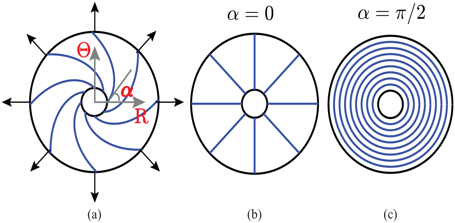
This work considers a plane annular membrane with inner radius , outer radius , and uniform thickness , with . The membrane is formed from a homogeneous incompressible nonlinear elastic material reinforced by an axisymmetric distribution of fibers lying in a plane parallel to the midsurface. Each fiber has the shape of a plane spiral curve that extends from the inner to the outer radius. This is taken to be a stress-free reference configuration for the membrane material and fibers (Figure 1). The membrane is attached to a rigid circular disc at the inner boundary. An initial radial stretch may be imposed on the membrane by displacing the outer boundary so that it is held fixed at some specified radius . The fibers lie parallel to the midsurface and are distributed in a radial, circular, or spiral pattern (see Figure 1). Membranes have generally been loaded by specifying displacement or traction on their circular boundaries or by pressure on their lateral surface [11, 18–21, 23]. When there is no mechanical loading, corresponding to a fixed outer boundary, this work investigates the effects of loading generated when the fibers are exposed to UV light and contract, i.e., there is a non-mechanical trigger. Suppose the membrane is exposed to UV light of wavelength 436 nm. Because the fibers have spiral shapes and their ends are held at fixed radii, it is expected that the contraction of the fibers will lead to a shape change, a shearing deformation within the membrane, a distribution of shear stresses on the cylindrical surface of the rigid disc, and thus a resultant moment about its centerline. This response is motivated by that in the work by Demirkoparan and Pence [24] which treated a circular cylinder of spirally shaped fibers embedded in an elastic material. It was shown that swelling of the elastic constituent led to shearing deformations and twisting. The purpose of this study is to relate the activation due to UV light, the properties of the fibers, and their spiral shape to the torque on the disc. The resulting stress and stretch ratio distributions are determined for each of the fiber patterns. The finite element (FE) method is used to examine whether wrinkling occurs and the effects of fiber patterns on instability shape. The combined mechanical and non-mechanical loading by prescribing a stretch to the outer boundary is also examined.
A schematic representation of an annular membrane reinforced with various fiber patterns subjected to radial stretching at the outer boundary. Cylindrical coordinates are considered with in the underformed configuration and in the deformed configuration. The fibers are oriented as (a) spiral fibers, (b) radial fibers, or (c) circumferential fibers. Note that (b) and (c) are special cases of (a) and correspond to specific choices of spiral fibers where the angle of the tangent vector to the fiber with respect to the radial axis becomes or , respectively. The fiber-reinforced annular membrane is fixed at the inner circular boundary.
The constitutive model is presented in section 2, and the governing equations for the membrane response are formulated in section 3. The governing equations are solved by two methods: (1) formulating and solving as a system of ordinary differential equations (ODEs) and (2) solving with FE method, aspects of which are described in section 4. Section 5.1 contains numerical results for radial, circular, and spiral fiber distributions for different amounts of fiber contraction. Shear stresses are produced in the case of spiral fibers. These produce a resultant moment about the axis of symmetry on the boundaries. The dependence of this moment on the spiral shape and the amount of fiber contraction are calculated. It was found that there can be annular regions within the membrane in which the minimum principal stress is negative, indicating regions of wrinkling. The possibility that these regions can be eliminated by stretching the membrane is explored in section 5.2. Concluding comments are in section 6.
2. Constitutive model
Consider a fiber of a material whose length changes in response to some non-mechanical influence such as a change in temperature or radiation from an UV light source. When there is no non-mechanical influence, the fiber length is . Let denote a parameter that indicates a measure of the intensity of this non-mechanical influence. If the fiber is unconstrained and this non-mechanical influence is activated to an intensity , the free length of the fiber is . It is assumed that the fiber contracts so that . The corresponding stretch ratio due to activation is:
If this non-mechanical influence is activated when the fiber is constrained by an applied force, the observed length is and the observed stretch ratio is
Using the approach in Nardinocchi and Teresi [25] and Wineman [26], the observed stretch ratio is decomposed into mechanical and activated factors,
where
It is assumed that the stress depends on .
These notions are now presented in a three-dimensional setting. Let and denote the common reference and current configurations, respectively, for the matrix and fiber. Let the position vectors of a particle in these configurations be and . The deformation gradient comparing to is and the right and left Cauchy–Green tensors are , . The usual invariants of are . The invariants of are obtained by substituting for . It will be assumed that the material system is incompressible, so that .
When a non-mechanical influence is activated to an intensity and there is unconstrained response, configuration becomes configuration and their connection is . If there is an applied force, becomes and their connection is . Then, as developed in the work by Nardinocchi and Teresi [25],
Let be a unit vector tangent to a point along a fiber in the reference configuration. The lengths of a differential segment of the fiber in the reference and current configurations are and , respectively. A typical differential line element of a fiber in the reference configuration becomes , where is a unit vector along the fiber in the current configuration. Then, by equation (4),
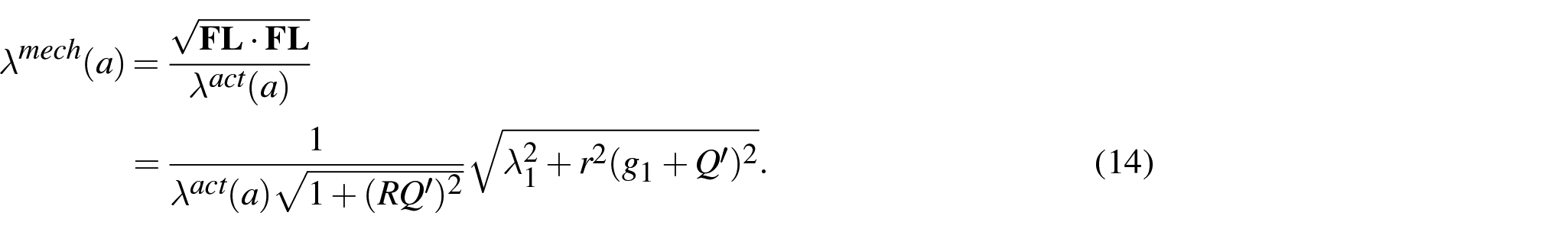
represents the mechanical stretch along the fiber in the current configuration. The scalar is an invariant that arises in treatments of nonlinear elastic fiber-reinforced materials. has the geometric interpretation of being the square of the observed stretch ratio of the fiber, . Then, by equation (3), the mechanical stretch ratio of the fiber is .
In much of the literature on the mechanics of nonlinear elastic fiber-reinforced materials, there is the underlying assumption that the matrix and fiber constituents share a common reference configuration that each constituent is stress-free in this configuration and that they have the same deformation gradient. The matrix-fiber system is considered homogenized and treated as an equivalent single-constituent transversely isotropic nonlinear elastic material. The system could also be treated as a mixture of matrix and fibrous constituents, each with its own reference configuration and properties. The conditions under which the constitutive equation for the total stress in the mixture can be transformed into a constitutive equation for an equivalent single-constituent transversely isotropic nonlinear elastic material have been discussed in the work by Pence and Wineman [27]. In this work, where the reference length for the mechanical deformation of the fiber can change due to activation, it is more satisfying to treat the system as a mixture of matrix and fiber constituents. The total stress is the sum of partial stresses for the matrix and fiber, each given by a separate constitutive relation with its own reference configuration and properties.
The total stress is assumed to consist of contributions from the constituents in the form
where is the reaction stress due to a constraint. is the stress due to the matrix and it depends on the deformation gradient from the original reference configuration. is the stress due to the fiber and it depends on the deformation gradient from the activated configuration. For the purposes of providing numerical examples, it is assumed that the material is incompressible and the constitutive equation is an adaptation of the standard reinforcing model in the work by Qiu and Pence [28]
where the first term is the reaction stress due to incompressibility, the second assumes the matrix acts as a Mooney–Rivlin material with modulus and Mooney–Rivlin parameter . The last term is motivated by the standard reinforcing model [28]. Only the invariant whose geometric interpretation is the square of the fiber stretch is used to formulate the constitutive relation here. Previous work by Murphy and others [29, 30] shows that it might be necessary to incorporate the invariant to better capture shear modes. The importance of and potential issues of neglecting this invariant for this study can be investigated in future work. Note that
where is the fiber stiffness. When or equivalently there is no non-mechanical activation, the model reduces to the traditional nonlinear elastic reinforced material model.
3. Formulation
The governing equations are formulated using the membrane approximation, whereby a physical entity is evaluated on the midsurface and its variation in the direction normal to the midsurface is neglected. Cylindrical polar coordinates are used in both the initial configuration and the current configuration . The orthonormal unit vectors in the reference and current configurations are denoted by and , respectively.
The fiber description here is a summary of that in the work by Demirkoparan and Pence [24], where full details can be found. First, consider the fiber layout in the reference configuration. For the fiber beginning at , , its curve is described by with and , the angular offset. The fiber curve beginning at any other angle is described by . The unit vector in the reference configuration that is tangent to the fiber at is
the prime denoting differentiation with respect to . In this work, the fiber geometry is described as a logarithmic spiral , where is the angle between the tangent to the spiral and at . For a logarithmic spiral, is a constant. corresponds to radial fibers, while corresponds to circular fibers.
The deformation has the following form:
Using the notation , the deformation gradient is
Here is the radial stretch ratio, is the circumferential stretch ratio. Note that the stretches and are not the principal stretches when shear deformation occurs (i.e., in the spiral fiber-reinforced membranes). The incompressibility condition implies that the thickness stretch ratio is given by:
In the membrane formulation, which gives . Moreover, the equilibrium equations for the membrane are expressed in terms of the stress resultants
The equation expressing equilibrium in the radial direction is
and in the circumferential direction
Substitution of equations (16) and (17) into equations (20), and equation (18) into equation (21), and using the expression for in terms of shown above, leads to two ODEs in terms of . For the convenience of formulating and numerically solving an ODE system , the constitutive and governing equations are formulated as functions of 5 variables as discussed in section 4.1.
4. Boundary value problems: methods of numerical solution
4.1. Formulating and solving as a system of ODEs
With equations (16)–(19), the two governing equations (21)–(22) in terms of in section 3 can be used to derive and as functions of . This together with and leads to a system of four ODEs of the following forms:
where .
Since the inner surface of the membrane is fixed, two boundary conditions are and . The boundary conditions at the outer surface are and , where is the applied outer stretch.
The solution process starts with assuming together with two boundary conditions . A fourth-order Runge–Kutta procedure is used to integrate the ODE system (23) to determine and . These values will be compared with the specified boundary conditions at the outer surface and . When the differences are not small enough, a Newton’s scheme is used to modify the guessed values at the inner surface and and the Runge–Kutta procedure is repeated. This iterative process is performed until the boundary conditions are all satisfied.
4.2. Solving by FE method
The constitutive model is implemented as a VUMAT material subroutine for membrane elements in the commercial FE software ABAQUS [31, 32]. Using the incompressibility condition , the component of the deformation gradient in the thickness direction is determined: . The stresses are updated using equations (16)–(18). Additional details of the VUMAT implementation are presented in Appendix 1.
The membrane is fixed at the inner surface in all degrees of freedom, while the outer surface is fixed in the through thickness and circumferential directions and is subjected to a radial displacement of . Without any out-of-plane perturbation, the FE solutions are used to cross-check with the solutions from formulating and solving an ODE system approach. A small out-of-plane pressure is applied to trigger instability if negative stresses occur.
5. Boundary value problems: results and discussions
A number of different boundary conditions on the outer radii are considered. The following calculations were performed for a membrane with the ratio between the outer radius and the inner inclusion’s radius . The ratio for mismatch stiffness between fibers and matrix is assumed if not stated explicitly. The following results are considered for three values of the activation stretch, , and for spiral fiber orientations: (radial fibers), (spiral fibers), and (circumferential fibers).
5.1. Fixed inner and outer radii
To elucidate the effects of the non-mechanical activation, the inner and outer surfaces of the membrane are held fixed at their undeformed radii. In other words, the applied stretch at the outer surface is .
5.1.1. Radial fibers
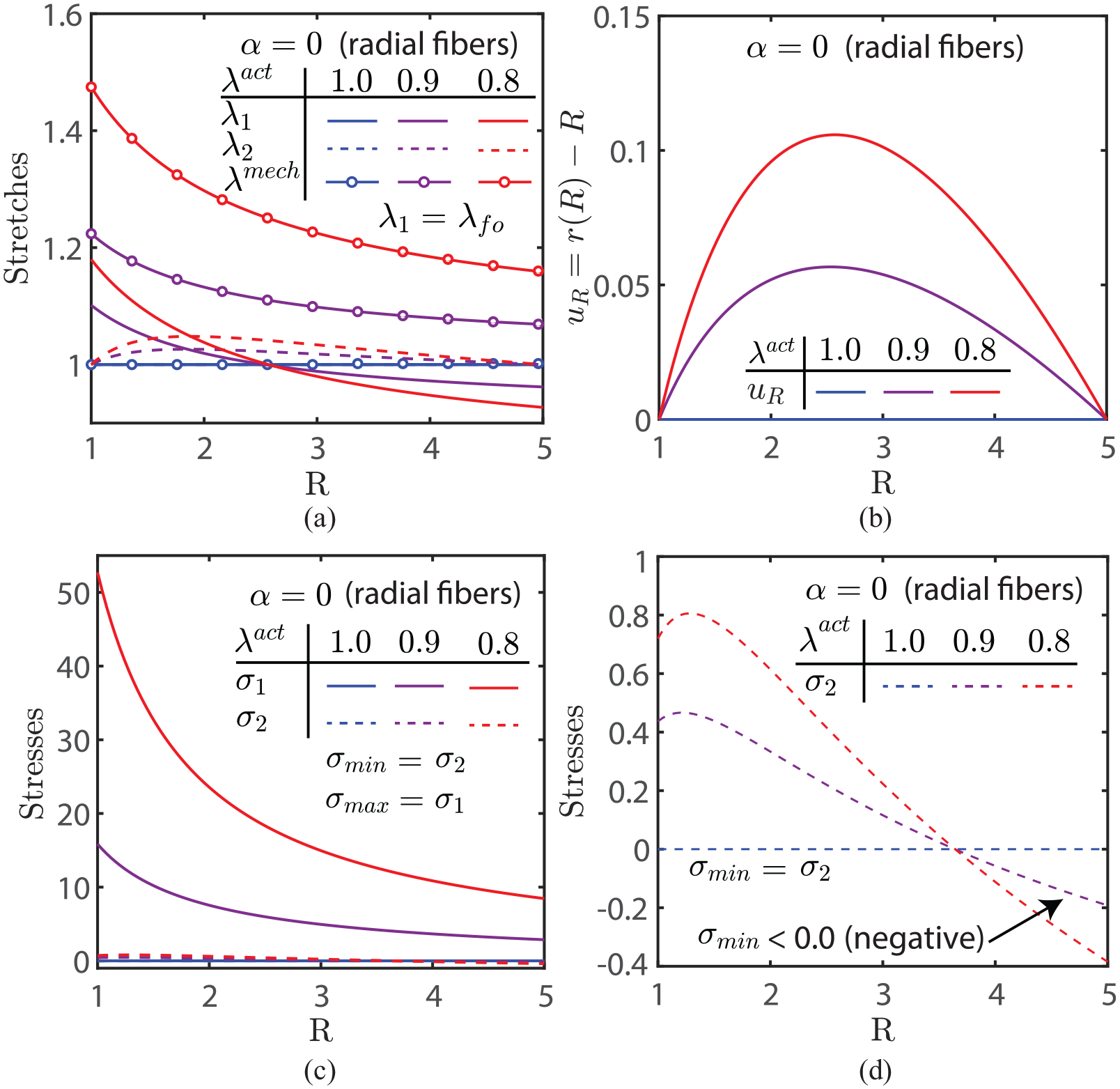
Figure 2(a) shows the radial distributions of and when the fibers are oriented in the radial direction. When , there is no fiber contraction and . When , varies from greater than 1 near the inner radius to less than 1 near the outer radius while is greater than 1 for all radii. Note that is the observable stretch in the fiber, but it is not the mechanical stretch. Since and , the mechanical stretch in the fiber also shown in Figure 2(a) is which is non-homogeneous through the membrane. As the active fibers are in the radial direction, is both the observable and the mechanical circumferential stretch in the matrix. It is greater than 1 for all radii. This is consistent with the particle positions in the deformed state shown through their radial displacements as a function of the undeformed radius in Figure 2(b). The increase in radial displacements shows that the particles in between the two inner and outer surfaces move toward the outer surface with a rate of movement that increases then decreases spatially from the inner to outer radii. Figure 2(c) and (d) shows the stress distributions. The radial stresses are tensile for all radii and are highest at the inner boundary and lowest at the outer boundary. The circumferential stresses are slightly negative near the outer radius as shown in Figure 2(d). The circumferential stress also has a local maximum near but not at the inner surface. An increase in fiber contraction leads to more significant negative circumferential stress. As these are mainly stresses in the matrix, the membrane may wrinkle near the outer radius. These distributions are confirmed using FE simulations (see Figure 3) and the effects of negative stress inducing wrinkling will be explored in section 5.1.4 (see Figure 9).
Radial fiber-reinforced membrane with , , , and three amounts of activation : (a) Radial distributions of stretches: and are observable stretches along the radial and circumferential directions, respectively; is the mechanical stretch along the fiber direction (radial). The observable stretch along the fiber direction in this case is . (b) Radial displacements of particles with respect to radial positions. (c) Radial distributions of stresses: and are radial and circumferential stresses, respectively; they are also principal stresses. (d) An expanded vertical axis view of the radial distributions of stresses shows negative circumferential stresses (minimum principal stresses) near the outer radii due to fiber contraction. Note: all the stresses here and in the following figures are normalized with respect to .
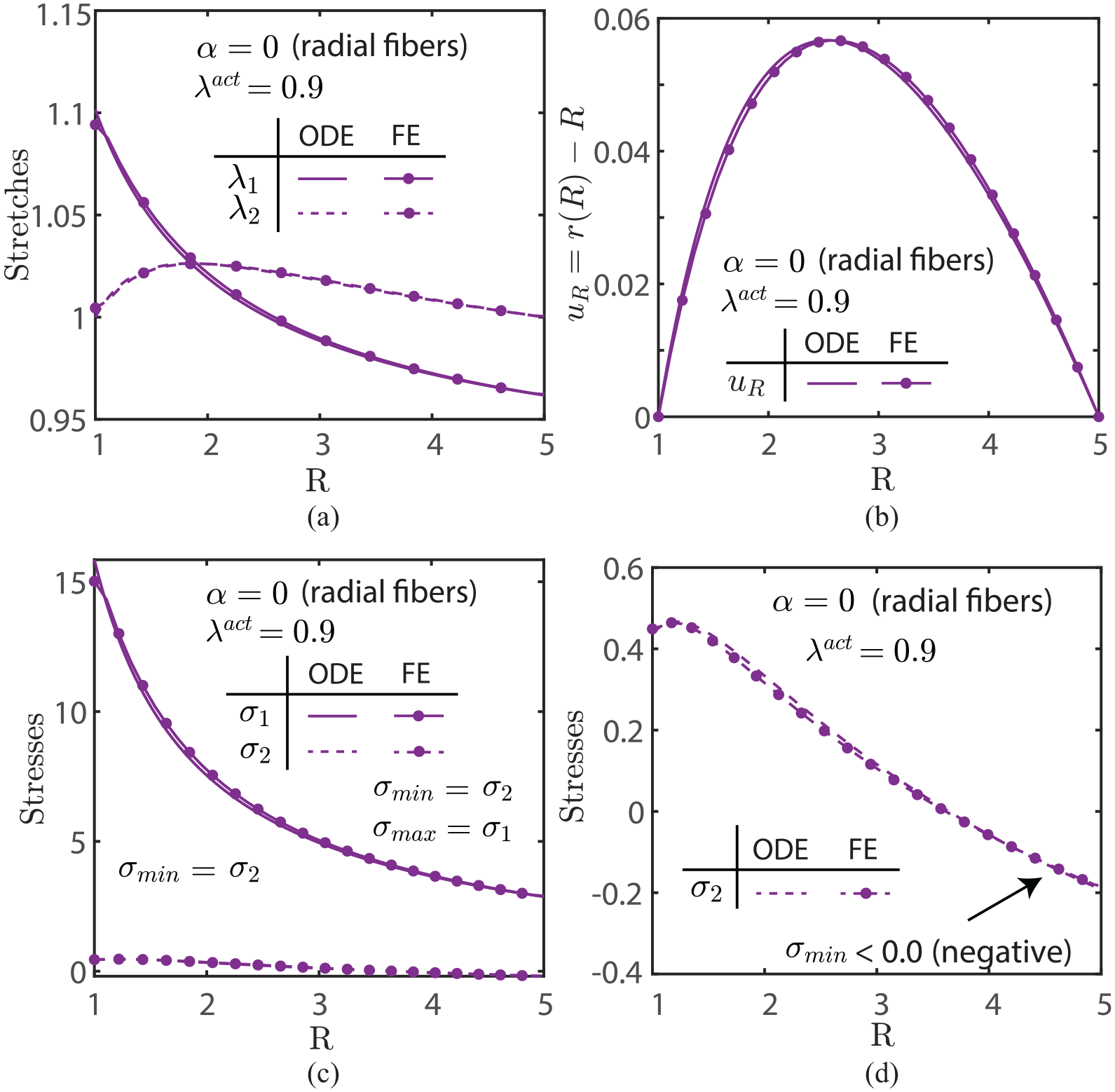
FE simulations of radial fiber-reinforced membrane with , , , and as compared to the solutions obtained from solving a system of ODEs (corresponding purple curves in Figure 2(a)–(d), respectively) : (a) and . (b) . (c) and . (d) An expanded vertical axis view of the radial distribution of stress shows that the minimum principal stress reaches a maximum near the inner surface. Both solution methods are in good agreement.
5.1.2. Circumferential fibers
Figure 4(a) shows the radial distributions of and when the fibers are oriented in the circumferential direction. is the observable circumferential stretch in the fiber and for all radii. As in the case of radial fibers, the mechanical stretch in the circumferential fiber is , as shown in Figure 4(a). is both the observable stretch and mechanical stretch, mostly from the matrix. It is less than 1 near the inner radius and greater than 1 near the outer radius. The explanation for this follows from the plot of vs in Figure 4(b). When the circumferential fibers are activated, the radii of all particles decrease, which is opposite to the radial fiber case (Figures 2(b) and 3(b)). The matrix material near the outer radius is stretched radially and the material near the inner radius is compressed radially. Figure 4(c) shows the stress distributions. The circumferential stresses in the fibers are all tensile and decrease from a local maximum at the inner radius to a minimum near and then increase to another local maximum at the outer radius. However, the radial stress is compressive near the inner radius, suggesting wrinkling in that region. These results are also explored by FE simulations. Consistent predictions of the radial stretch, displacement, and stress distributions are obtained from FE solutions as compared with the solutions obtained from solving a system of ODEs. Note that for brevity, the results for the circumferential fibers are not presented (such a comparison for the radial fiber case is shown in Figure 3).
Circumferential fiber-reinforced membrane with , , , and three amounts of activation : (a) Radial distributions of stretches: and are observable stretches along the radial and circumferential directions, respectively; is the mechanical stretch along the fiber direction (circumferential). The observable stretch along the fiber direction in this case is . (b) Radial displacements of particles with respect to radial position. (c) Radial distributions of stresses: and are radial and circumferential stresses, respectively; they are also principal stresses.
5.1.3. Spiral fibers
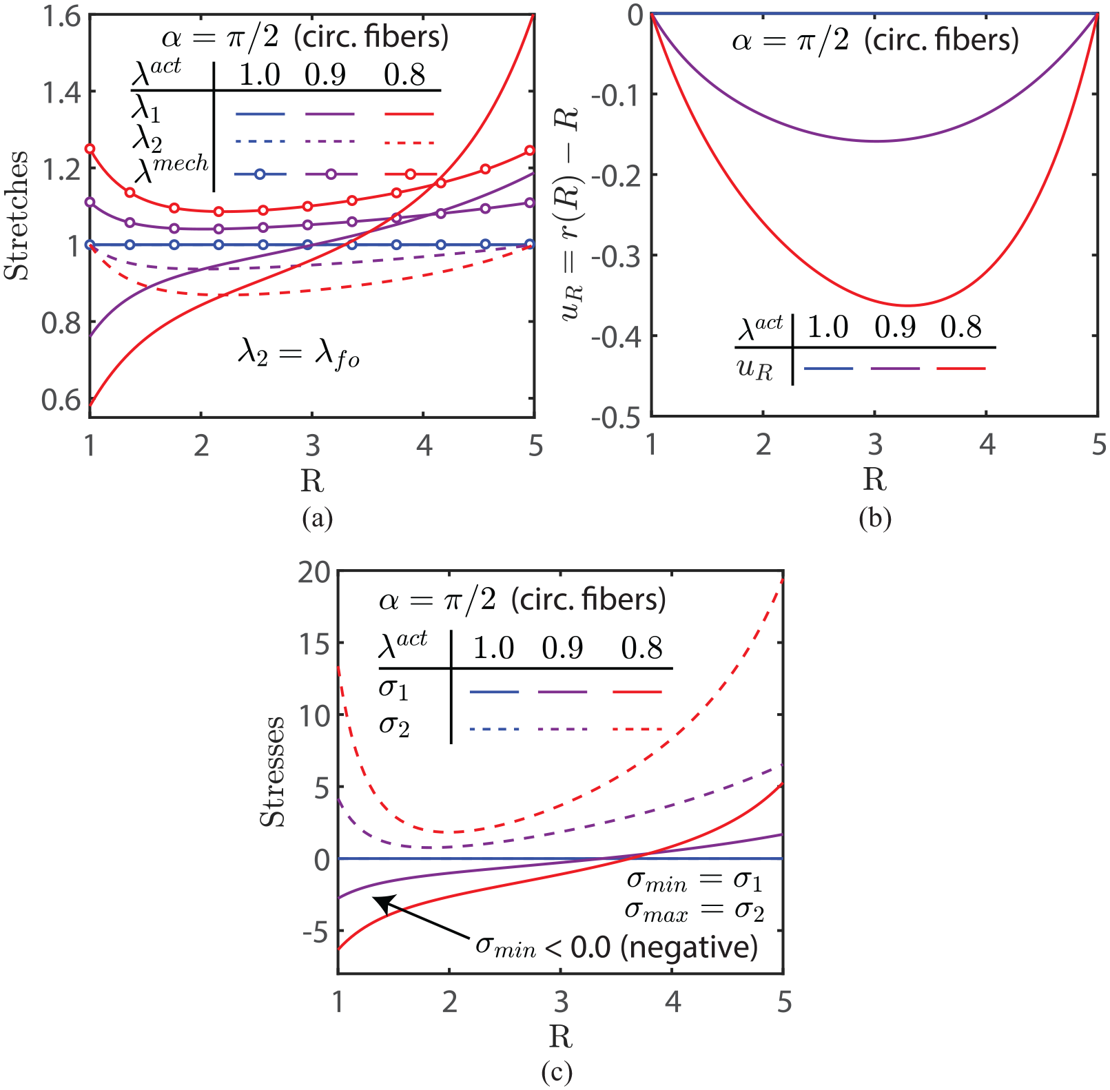
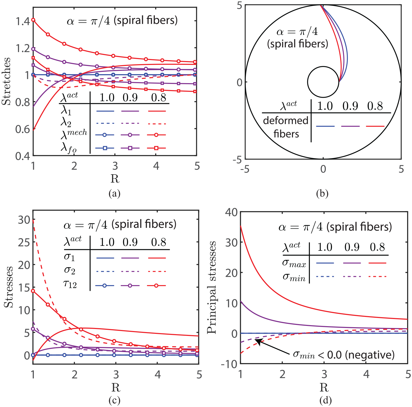
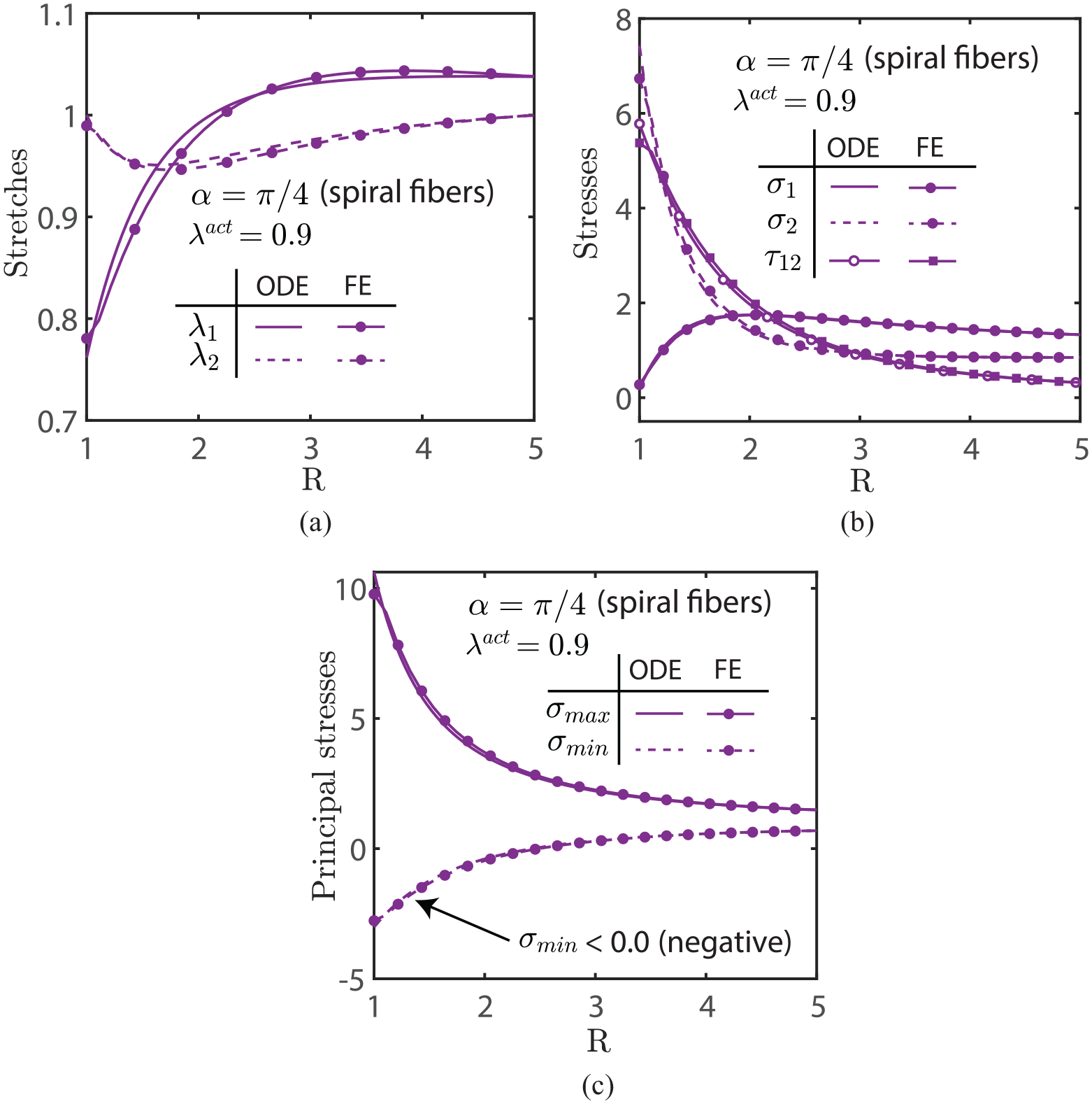
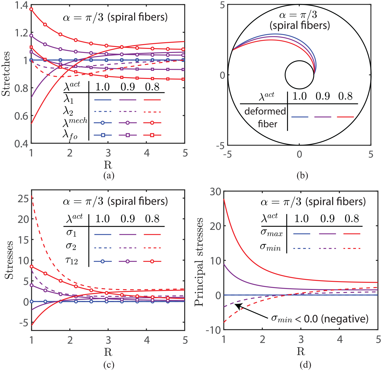
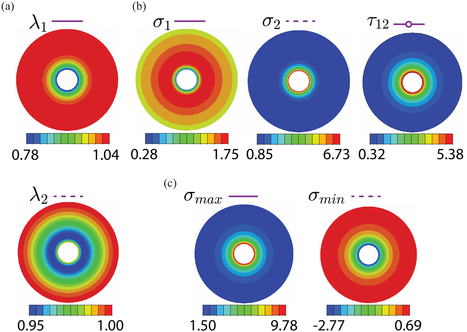
The results in this section consider the mechanics of membranes with spiral fiber reinforcement. The next set of figures shows the influence of spiral fibers with when there is contraction due to activation. Figure 5 is for , Figures 6 and 7 are for , and Figure 8 is for . The general features of the distributions are similar for all three values of , but the magnitudes of stretches and stresses have a strong dependence on the value of . Each of Figures 5(a), 6(a), and 8(a) shows the radial distributions of observable total stretches in the radial and circumferential directions (), the observable stretch in the fiber, , and the mechanical stretch along the fiber direction (). are now stretches in the matrix/fiber system. in an annular region near , with its smallest value at . It increases with and becomes greater than in the outer annular region. for and equals 1 only at and . The observable stretch in the fiber, decreases monotonically from greater than near to less than in the outer annular region. The mechanical stretch along the fiber direction () is greater than for all radii and decreases monotonically from its maximum at to a minimum at . The magnitudes increase significantly when changes from to , i.e., when the stress-free length of a fiber becomes shorter. Figures 5(b), 6(b), and 8(b) show the changes in the shape of the spiral as activation increases. Figures 5(c), 6(c), and 8(c) show the radial distributions of radial (), circumferential (), and shear stresses, now stresses in the combined matrix fiber system. Figures 5(d), 6(d), and 8(d) also show the principal stresses and . The maximum principal stresses are positive for all radii, but the minimum principal stresses are negative in an annular region and become positive for , for a value of near that depends on . This is due to the presence of the shear stresses shown in Figures 5(c), 6(c), and 8(c). The shear stress is maximum at and decreases with . The twisting moment M that acts on the inner support increases with increasing activation . The values of at three activation values of , respectively, are 0, 8.63, 29.88 for ; 0, 7.59, 24.28 for , and 0, 5.42, 15.68 for . Results from FE simulations presented in Figure 7 for show good agreement with the stretch and stress distributions obtained by formulating and solving a system of ODEs in Figure 6 (similar comparisons are also obtained for other angles but are not presented for brevity). The visualization of these distributions are also shown in Figure 14 in Appendix 1. Negative values of the minimum principal stress are obtained consistently at the inner radius.
Spiral fiber-reinforced membrane with , , , , and three amounts of activation : (a) Radial distributions of stretches: and are observable stretches along the radial and circumferential directions, respectively. The observable stretch along the fiber direction in this case is and the mechanical stretch along the fiber direction (). (b) Deformed shape of the spiral fiber. The shape that corresponds to is also the undeformed shape of the spiral fiber (blue curve). (c) Radial distributions of stresses: , , are radial, circumferential, and shear stresses, respectively. Shear stress is increased with more contraction in the fibers resulting in an increase in twisting moment about the centerline. (d) Radial distributions of principal stresses: and are not the same as the radial and circumferential stresses in this case. Negative minimum principal stresses occur near the inner radii due to fiber contraction.
Spiral fiber-reinforced membrane with , , , , and three amounts of activation : (a) Radial distributions of stretches: and are observable stretches along the radial and circumferential directions, respectively. The observable stretch along the fiber direction in this case is and the mechanical stretch along the fiber direction (). (b) Deformed shape of the spiral fiber. The shape that corresponds to is also the undeformed shape of the spiral fiber (blue curve). (c) Radial distributions of stresses: , , are radial, circumferential, and shear stresses, respectively. Shear stress is increased with more contraction in the fibers resulting in an increase in twisting moment about the centerline. (d) Radial distributions of principal stresses: and are not the same as the radial and circumferential stresses in this case. Negative minimum principal stresses occur near the inner radii due to fiber contraction.
FE simulations of spiral fiber-reinforced membrane with , , , , and as compared to the solutions obtained from solving a system of ODEs (corresponding purple curves in Figure 6(a), (b), (d), respectively): (a) and . (b) , , and . (c) and . Both solution methods are in good agreement.
Spiral fiber-reinforced membrane with , , , , and three amounts of activation : (a) Radial distributions of stretches: and are observable stretches along the radial and circumferential directions, respectively. The observable stretch along the fiber direction in this case is and the mechanical stretch along the fiber direction (). (b) Deformed shape of the spiral fiber. The shape that corresponds to is also the undeformed shape of the spiral fiber (blue curve). (c) Radial distributions of stresses: , , are radial, circumferential, and shear stresses, respectively. Shear stress is increased with more contraction in the fibers resulting in an increase in twisting moment about the centerline. (d) Radial distributions of principal stresses: and are not the same as the radial and circumferential stresses in this case. Negative minimum principal stresses occur near the inner radii due to fiber contraction.
5.1.4. Fiber contraction inducing wrinkling
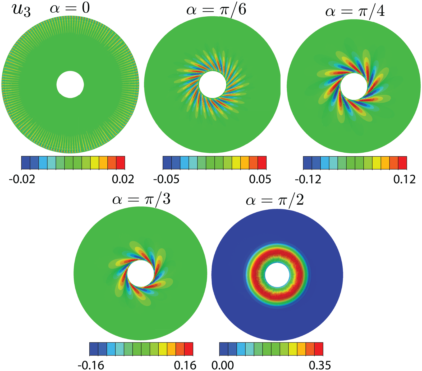
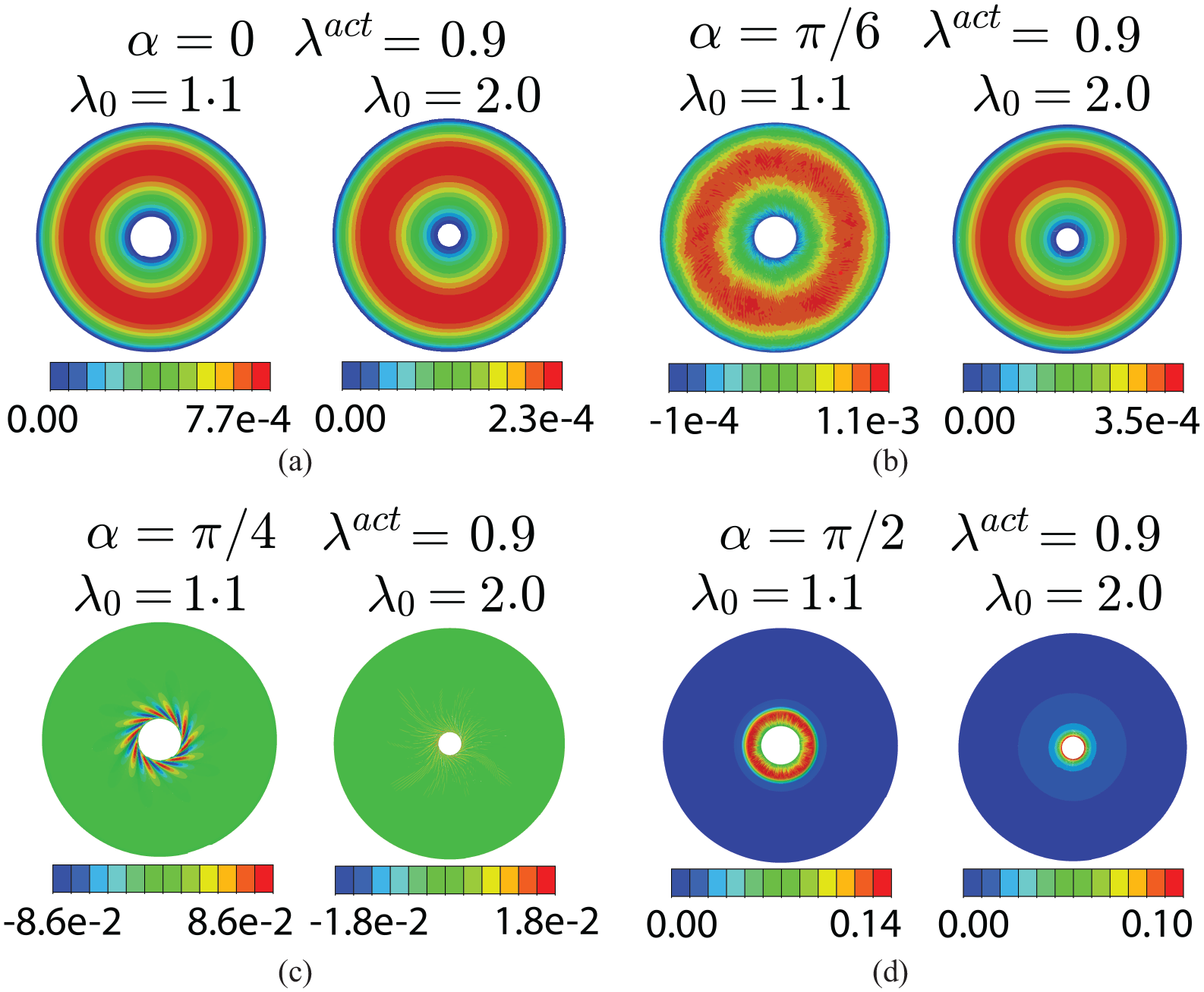
Triggering out-of-plane perturbation in the FE simulations leads to interesting spiral wrinkle patterns where the number of wrinkle reduces and the wrinkle amplitude increases as the angle increases as shown in Figure 9. The wrinkles are postulated to arise to release the negative stresses generated by fiber contraction.
Out-of-plane displacement are obtained from FE simulations of spiral fiber-reinforced membrane with , , , and with out-of-plane perturbation for different spiral fiber patterns. The number of wrinkles becomes coarser and the wrinkle amplitude is also increased when increases. The wrinkling occurs in the regions of negative minimum principal stresses which are in good agreement with the corresponding purple curves in Figures 2–8.
5.2. Fixed inner radius and increased outer radius
This section considers the membrane that is subjected to an applied stretch of . Specifically, two values are used. For brevity, this section will only present the distributions of principal stresses from formulating and solving a system of ODEs approach and FE simulations with out-of-plane perturbation to study the influence of radial stretching the membrane on wrinkling. The large stretching generates very large stresses in the membrane, so unlike section 5.1, the distributions here will be plotted using logarithmic values of the stresses. Negative stresses will show no presence in these plots.
5.2.1. No fiber activation
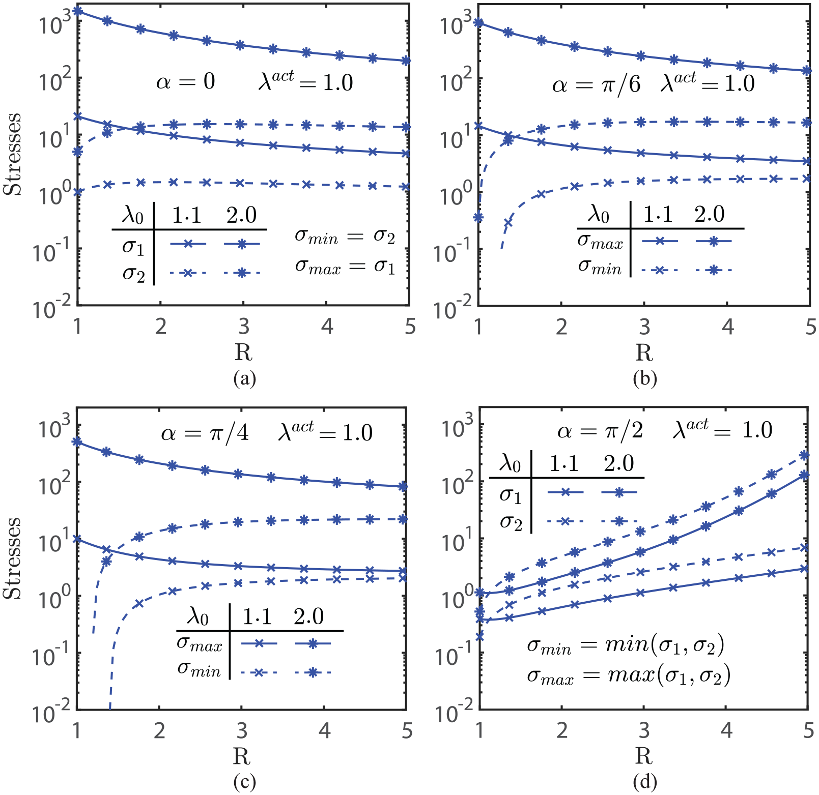
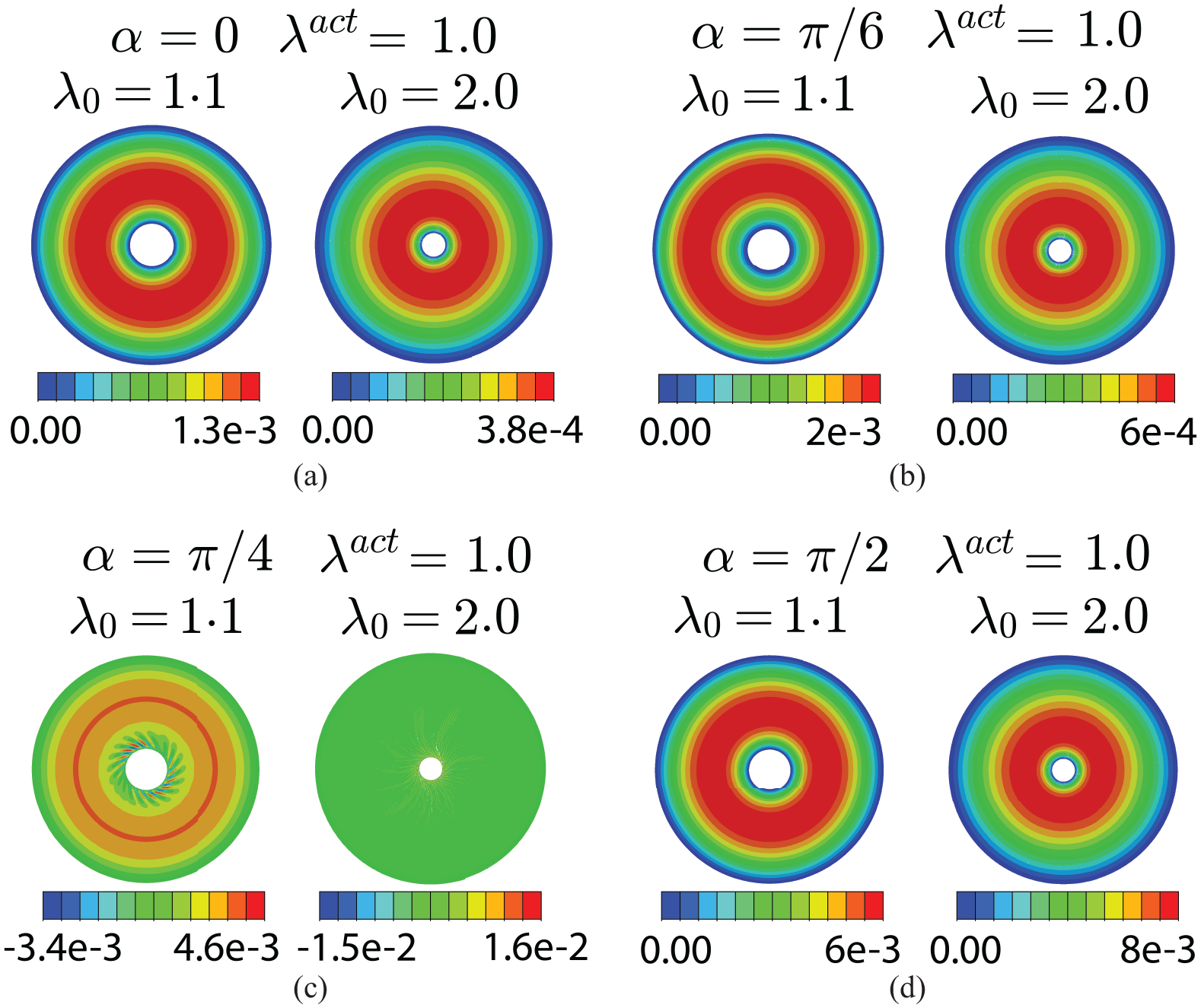
Let there be no activation . The problem reduces to the stretching of a traditional nonlinear fiber-reinforced membrane with the special case of the non-reinforced membrane studied by Yang [11]. We have confirmed the agreement with Yang et al. in this special limit (results not shown). Figure 10 shows the radial distribution of the minimum principal stress for different values of . For radial () and circumferential () fibers, the minimum principal stresses are positive at all radii. For other values of , there is a region near the inner radius where the minimum principal stress is negative, indicating a wrinkled zone. FE simulations with out-of-plane perturbation are used to examine the effects of these stress distributions on wrinkling (see Figure 11).
Spiral fiber-reinforced membrane with , , (no activation), and two levels of applied stretch : (a) For (radial fibers), the maximum and minimum principal stresses are the radial and circumferential stresses, respectively, for all radial positions which are all positive. (b) and (c) For and (spiral fibers), the maximum and minimum principal stresses are not the radial and circumferential stresses. The minimum principal stresses are negative near the inner radius. Increasing the amount of stretch reduces the regime of negative stress. (d) For (circumferential fibers), the principal stresses are the circumferential and radial stresses. The maximum (minimum) principal stresses can be either radial (near the inner radius) or circumferential (toward outer radius). All principal stresses are positive.
The out-of-plane displacement () from FE simulations of spiral fiber-reinforced membrane with , , (no activation), and two levels of applied stretch with out-of-plane perturbation for different spiral fiber patterns: (a) for : is only slightly perturbed due to the applied perturbation. No wrinkling occurs as all the principal stresses are positive (Figure 10(a)). (b) For : field also shows no wrinkling. Negative minimum principal stresses occur within a narrow region near the inner radius; we postulate that these stresses are not significant enough to induce wrinkling for small angle of spiral fibers (Figure 10(b)). (c) For : there is a signature of low amplitude spiral wrinkling that occurs at both the low and high applied stretch (see corresponding stress distribution in Figure 10(c)). (d) For : similar to the radial fiber case, no wrinkling occurs as all the principal stresses are positive (Figure 10(d)). Increasing the amount of stretching tends to decrease .
5.2.2. With fiber activation
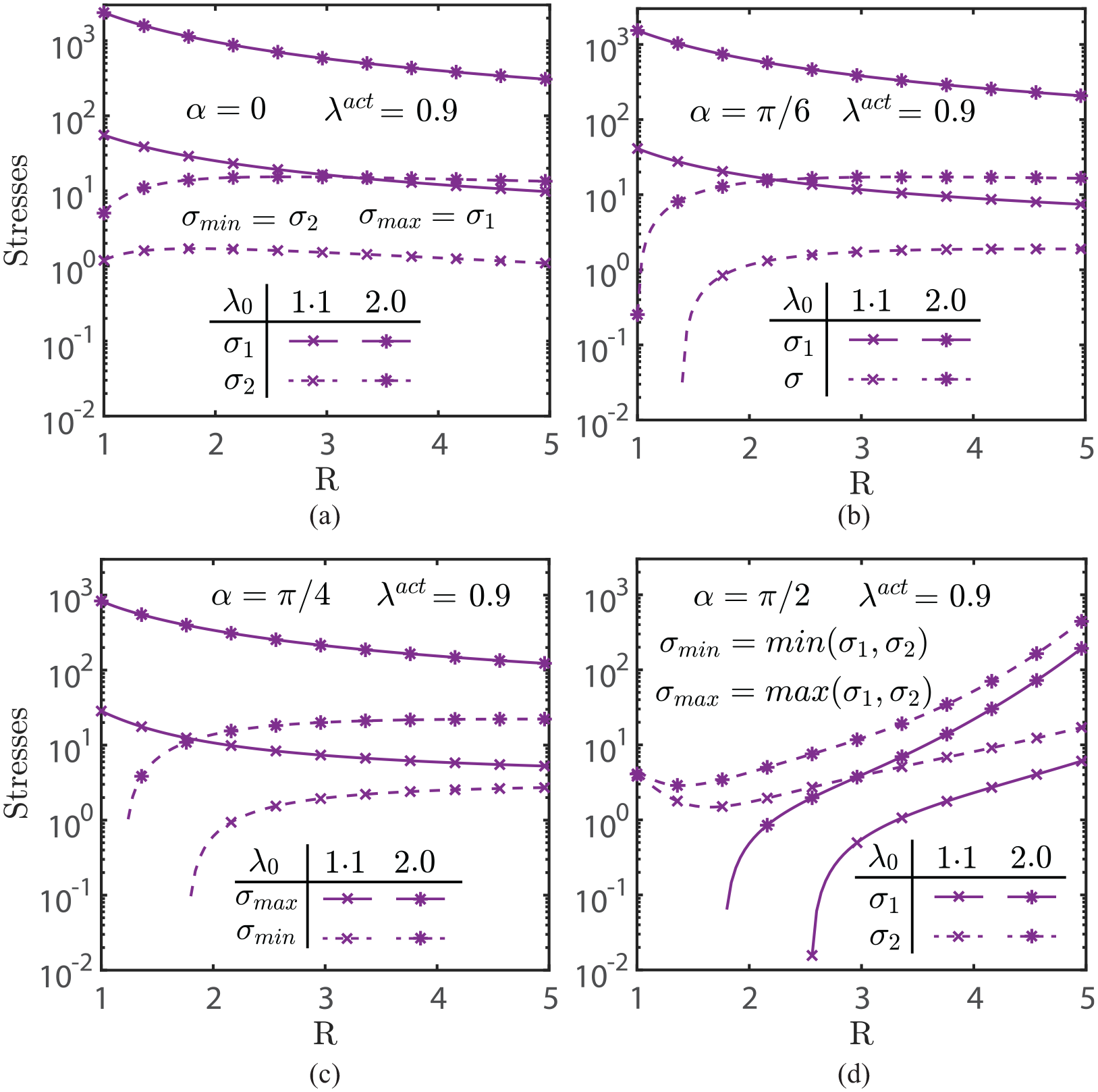
The activation of the radial, circumferential, and spiral fiber distributions was shown to produce compressive stresses in the membrane. The outer stretch reduces the regime of negative stresses. These suggest considering the effect on the compressive stresses of stretching the membrane reinforced by activated fibers. The following results are for membranes with subjected to outer stretches of and . Figures 12 and 13 show that a high outer stretch can eliminate the compressive stresses for spiral fibers at low spiral angles.
Spiral fiber-reinforced membrane with , , (with activation), and two levels of applied stretch : (a) For (radial fibers), the maximum and minimum principal stresses are the radial and circumferential stresses, respectively, for all radial positions which are all positive. (b) and (c) For and (spiral fibers), the maximum and minimum principal stresses are not the radial and circumferential stresses. The minimum principal stresses are negative near the inner radius. Increasing the amount of stretch reduces the regime of negative stress. (d) For (circumferential fibers), the principal stresses are the circumferential and radial stresses. The maximum (minimum) principal stresses can be either radial (near the inner radius) or circumferential (toward outer radius) the minimum principal stresses. The minimum principal stresses are negative near the inner radius with smaller negative region when the high amount of stretching is applied.
The out-of-plane displacement () from FE simulations of spiral fiber-reinforced membrane with , , (with activation), and two levels of applied stretch with out-of-plane perturbation for different spiral fiber patterns: (a) for : is only slightly perturbed due to the applied perturbation. No wrinkling occurs as all the principal stresses are positive (Figure 12(a)). (b) For : field also shows no wrinkling though is more perturbed than the radial case, especially at low stretching. Negative minimum principal stresses occur within a narrow region near the inner radius; we postulate that these stresses are not significant enough to induce wrinkling for small angle of spiral fibers (Figure 12(b)). (c) For : a spiral wrinkling pattern clearly occurs and high applied stretch flattens out these wrinkles (see corresponding stress distribution in Figure 12(c). (d) For : circumferential buckling occurs at both levels of stretches, with increasing the amount of stretching leading to a reduction of amplitude .
FE simulations of spiral fiber-reinforced membrane with , , , , and : (a) and . (b) , , and . (c) and . These results are in good agreement with the corresponding purple curves in Figure 6(a)–(d), respectively.
6. Concluding comments
This work has been motivated by the development of stimuli-sensitive polymers and their potential applications [5–7]. When used in conjunction with traditional polymers, this new class of materials introduces the possibility of new devices with new physical effects. This is illustrated here with the example of a planar annular membrane that is reinforced with stimuli-sensitive polymeric fibers. The specific stimuli-sensitive material treated is azobenzene, which contracts when exposed to UV light wavelength of 436 nm and recovers its original length with exposed to UV light wavelength of 345 nm [8–10].
The membrane was assumed to be a composite of a matrix of a traditional elastomer reinforced with an axisymmetric distribution of azobenzene fibers. The constitutive equation for the composite was based on that for the standard reinforcing material model in the theory nonlinear fiber-reinforced elasticity. The membrane was fixed to rigid supports at its inner and outer circular boundaries. Exposure to UV light acted as a non-mechanical trigger that caused the fibers to contract and induce a stress and deformation distribution within the membrane. This work has explored the influence of the amount of fiber contraction and the fiber layout on the stress and deformation distributions. Three fiber distributions were considered: radial, circumferential, and spiral. The spiral distribution was considered because it combined aspects of both the radial and circumferential distributions. Another reason was its use in a device in which the outer surface is attached to a fixed support, while the inner surface is attached to a rigid solid cylinder. When activated and contracted, the spiral fibers exert a moment on the inner cylinder about its axis of symmetry.
The numerical results provide useful insight into the influence of fiber contraction and shape on the stress and deformation distributions. These were shown to have a strong dependence on the fiber shape. In particular, the results show that compressive stresses can be produced in the membrane, leading to zones of wrinkling. A preliminary study was carried out to determine whether an outward radial stretching of the membrane could produce tensile stresses within the membrane that eliminated the compressive stresses and wrinkling. It was shown that there are conditions where this may be possible, but they depend on the amount of contraction and fiber shape. Future work that integrates FE simulations with analyses such as the WKB methods [21, 33, 34] will be useful to better understand wrinkle onset and profile.
Due to the apparent lack of data for the mechanical properties of azobenzene suitable for use in the constitutive equation presented here, this work should be regarded as a “broad brush” study of the mechanical response of the UV-activated fiber-reinforced membrane. The development of a potential device using a specific stimuli-sensitive material would require a more refined determination of its properties. Some properties are (1) the relation connecting the activation parameter to the intensity and duration of the stimulus, i.e., the UV light; (2) the influence of activation on the mechanical response of the fiber; (3) the multi-axial mechanical properties for sheets.
Furthermore, while this work focuses on UV-activated fiber-reinforced polymeric membranes, the developed models are adaptable to modeling biological structures that utilize activated fibers to change shape and deformations, opening a new direction for further studies.
Footnotes
Appendix 1
Funding
The author(s) received no financial support for the research, authorship, and/or publication of this article.
ORCID iD
Alan Stuart Wineman
References
1.
FarrugiaMWhitakerR.The search for the definition, etiology, and effective diagnosis of upper urinary tract obstruction: the Whitaker test then and now. J Pediatr Urol2019; 15: 18–26.
2.
BrasseurJNicosiaMPalA, et al. Function of longitudinal vs circular muscle fibers in esophageal peristalsis, deduced with mathematical modeling. World J Gastroentero2007; 13: 1335–1346.
3.
HuizingaJLammersWJ.Gut peristalsis is governed by a multitude of cooperating mechanisms. Am J Physiol Gastrointest Liver Physiol2009; 296: G1–G8.
4.
KierWSmithK.Tongues, tentacles and trunks: the biomechanics of movement in muscular-hydrostats. Zool J Linn Soc2008; 83: 307–324.
5.
LeanzaSYangJKaczmarskiB, et al. Elephant trunk inspired multimodal deformations and movements of soft robotic arms. Adv Funct Mater2024; 2400396.
6.
LaschiCCianchettiMMazzolaiB, et al. Soft robot arm inspired by the octopus. Adv Robotics2012; 26: 709–727.
TaylorMShiraniMDabiriY, et al. Finite elastic wrinkling deformations of incompressible fiber-reinforced plates. Int J Eng Sci2019; 144: 103138.
23.
WinemanA.Nonlinear viscoelastic membranes. Comput Math Appl2007; 52: 168–181.
24.
DemirkoparanHPenceT.Swelling-twist interaction in fiber reinforced hyperelastic materials: the example of azimuthal shear. J Eng Math2018; 109: 63–84.
25.
NardinocchiPTeresiL.On the active response of soft living tissues. J Elasticity2007; 88: 27–39.
26.
WinemanA.On the mechanical interaction of a boa constrictor and its prey. Int J Eng Sci2010; 48: 1671–1680.
27.
PenceTWinemanA.On some connections between equivalent single material and mixture theory model for fiber reinforced hyperelastic materials. Int J Non Linear Mech2012; 47: 285–292.
28.
QiuGPenceT.Remarks on the behavior of simple directionally reinforced incompressible nonlinearly elastic solids. J Elasticity1997; 49: 1–30.
29.
MurphyJ.Transversely isotropic biological, soft tissue must be modelled using both anisotropic invariants. Eur J Mech A/Solids2013; 42: 90–96.
30.
DestradeMDonaldBMurphyJ, et al. At least three invariants are necessary to model the mechanical response of incompressible, transversely isotropic materials. Comput Mech2013; 52: 959–969.