
Abstract
The fracture initiation likelihood of numerous offset interfacial cracks in a structure that comprises a functionally graded magneto-electro-elastic (FGMEE) layer, which is sandwiched between two distinct functionally graded material (FGM) layers of equal thickness, is examined in this study. One of the offset cracks is located centrally at the interface between the FGMEE strip and one FGM layer, while the other two are positioned symmetrically along the interface of the FGMEE and another FGM layer. The cracks are idealized as impermeable and are under the influence of in-plane magnetic and electric, and anti-plane mechanical loadings. The governing partial differential equations are reduced to a set of first-kind integral equations of singular type with the help of an integral transform approach. Owing to the complexity of the kernel, a numerical solution based on the Chebyshev polynomial is employed. At last, the expressions of stress intensity factor (SIF) are obtained at the crack tips. A comparative assessment is used to validate the findings. The study highlights, through detailed graphical illustration, the consequence of strips’ width ratio, non-homogeneity parameter ratio, interfacial crack length ratios, and applied electric–magnetic loadings on the normalized SIFs.
Keywords
1. Introduction
The concept of FGMs was originally introduced by researchers in Japan in the 1980s for aerospace thermal-barrier applications, where extreme temperature gradients of approximately 2000 K on the outer surface and 1000 K on the inner surface across a 10 mm thickness necessitated materials with continuously varying thermo-mechanical properties. FGMs are engineered such that the volume fractions of constituent phases vary smoothly along a prescribed direction, enabling the material composition to transition from 0% to 100% ceramic across the thickness. Functionally graded magneto-electro-elastic (FGMEE) composites are the result of extending the concept of FGM to magneto-electro-elastic materials in order to improve the reliability of composites. One benefit of these materials is that they lack both desirable boundaries and internal seams. Nevertheless, due to their intrinsic brittleness, crack initiation remains unavoidable in FGMEE materials. For this kind of material under magneto-electro-mechanical loading, strong field concentrations arise near crack fronts, thereby accelerating crack growth. Furthermore, it is inevitable to have holes, cracks, inclusions, dislocations, and other flaws to start during the manufacturing process. The investigation of the fracture behavior of FGMEE materials was prompted by these flaws, which can cause composites or structures to break prematurely at any time.
To date, several studies have contributed to the research domain of FGM [1–4]. Singh and Das [5] investigated the fracture response of multiple collinear Griffith cracks in an FGM medium under thermal, mechanical, and thermomechanical environments. Singh and Das [6] investigated the transient behavior of multiple collinear antiplane cracks in an FGM layer bonded between dissimilar elastic layers and subjected to shear-impact loading. For arbitrarily oriented interface-crossing cracks under combined thermal and mechanical fields, a comprehensive analysis was done in the work by Singh and Das [7]. An angled crack under steady-state temperature conditions was further investigated by Singh and Das [8]. The article by Singh [9] presents an analytical method for the random dynamic investigation of two parallel interfacial cracks in a strip of FGM bonded between two different elastic strips.
Furthermore, many researchers have focused on layered FGM and FGMEE composites. A cracked functionally graded piezoelectric–piezomagnetic strip under the impact of in-plane magnetic and electric and anti-plane mechanical loads was analyzed using the distributed dislocation technique proposed in the work by Mousavi and Paavola [10]. In the work by Bagheri and Lak [11], an FGM layer under antiplane loading that is sandwiched between two isotropic layers and deteriorated by several interface cracks is examined. The anti-plane problem of an FGMEE strip positioned between two functionally graded strips is analyzed in the work by Guo et al. [12]. In the work by Hu et al. [13], the problem of a crack in a functionally gradient piezoelectric interlayer between two different homogeneous piezoelectric half-planes that is subjected to both an in-plane electric loading and an anti-plane mechanical loading is studied. The dynamic anti-plane problem for an FGMEE strip is investigated in the work by Feng and Su [14], with an internal crack that is perpendicular to the boundary. The integral transform approach is used in the work by Hu and Chen [15] to analyze a moving crack that moves along the interface of magnetoelectroelastic and functionally graded elastic layers under in-plane magnetic and electric and anti-plane shear stress. In the work by Hu et al. [16], the same crack model was examined for dynamic analysis. Singh and Das [17] investigated the fracture properties of several parallel cracks in an FGMEE plane subjected to both permeable and impermeable boundary conditions. In the works by Singh [18, 19], the dynamic study of several interfacial permeable cracks originating from circular holes in two bonded semi-infinite functionally graded piezoelectric materials under the effect of steady-state SH waves is examined. The Green’s function method is utilized to get the solution of the boundary conditions.
In general, the cracks are modeled as electrically and magnetically impermeable in order to establish an analytically tractable framework for the fracture behavior of the layered FGMEE composite. This assumption represents a limiting case in which the crack surfaces completely obstruct the transmission of electric displacement and magnetic flux across the crack gap. From a physical standpoint, such a situation can be justified where the crack opening is occupied by voids, micro-gaps, oxidation layers, debonded interfaces, or non-conducting damaged regions, all of which possess significantly lower electric and magnetic permeability compared to the surrounding magneto-electro-elastic medium. Under these conditions, the continuity of coupled electromagnetic fields across the crack faces becomes negligible, and the impermeable idealization becomes meaningful. Furthermore, the impermeable crack model generally produces stronger field perturbations and higher crack-tip intensity measures compared to the permeable case [17]. For this reason, impermeable crack assumptions are widely employed in investigations of piezoelectric, piezomagnetic, and magneto-electro-elastic fracture problems as benchmark formulations for evaluating crack-tip singular behavior.
The combined influence of functional grading, crack offset geometry, interfacial interaction effects, layered structure, and loading behavior on the fracture characteristics is not considered to date. This study contributes toward filling this gap by exploring the fracture initiation likelihood of multiple offset interfacial cracks in a multi-layered composite having a core FGMEE strip sandwiched between two different FGM layers of identical thickness. The configuration includes one of the offset cracks located at the center of the interface of FGMEE and one of the FGM strips, whereas the other two interfacial cracks are situated at the interface of FGMEE and another FGM strip, as elaborated in subsection “Schematic description.” The offset cracks are under the influence of in-plane magnetic and electric, as well as anti-plane mechanical loadings. The interfacial cracks are impermeable in nature. The governing equations and other boundary-continuity conditions are discussed in subsection “Governing equations and related boundary conditions.” Section “Mathematical analysis” of the article describes the reduction of the governing field equations to a set of first-kind singular integral equations. The resultant integral equation is solved numerically using an approach including the Chebyshev polynomial because of the complex nature of the kernel, as explained in subsection “Numerical solution.” Finally, the expressions of crack-tip driving force parameters in terms of SIFs are obtained in section “Driving force parameters.” In section “Numerical outcomes and discussion,” some important results and discussion based on the geometrical and material parameters are analyzed. A verification of the findings with existing results is also presented in this article. With the aid of pictorial illustration, the consequence of strips’ width ratio, non-homogeneity parameter ratio, interfacial crack length ratios, and electric–magnetic loadings on the normalized SIFs is examined. Section “Concluding remarks” concludes the article with some concluding comments. At the end of the article, Appendix 1 and references are given.
2. Problem formulation
2.1. Schematic description
The geometrical diagram of the problem is illustrated in Figure 1. The composite under discussion is composed of two different FGM strips of thickness h and an FGMEE strip of thickness
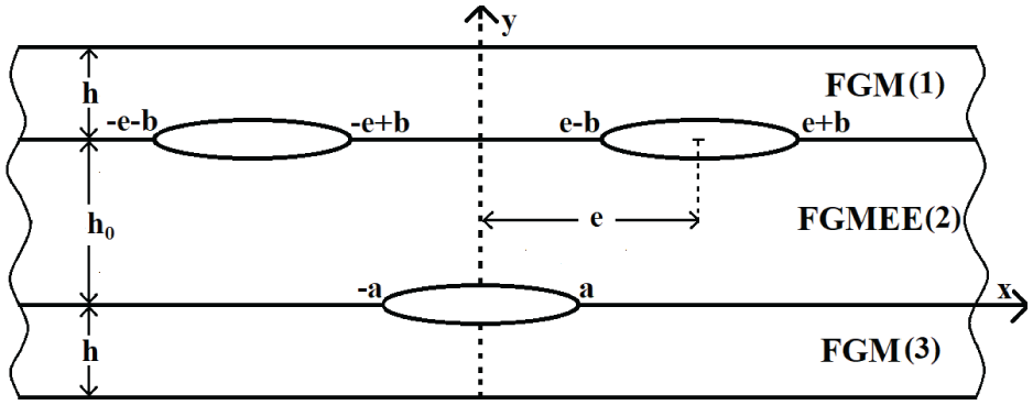
Geometric configuration of the problem.
The mechanical parametric functions, namely shear modulus for strips (1) and (3), are given by

and for the strip (2) magnetic permeability, shear modulus, dielectric, piezoelectric, magneto-electric, and piezomagnetic constants, respectively, are given by

where
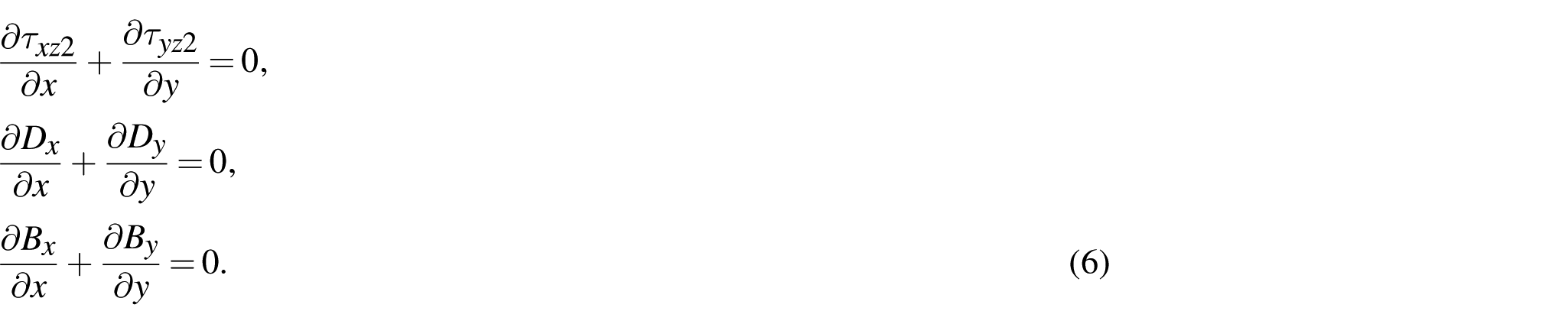
2.2. Governing equations and related boundary conditions
The constitutive equation for FGM strips is given by

and those for the FGMEE strip are given by
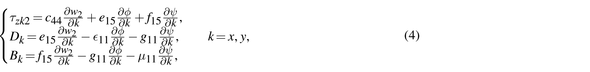
where

and those for the FGMEE strip are given by
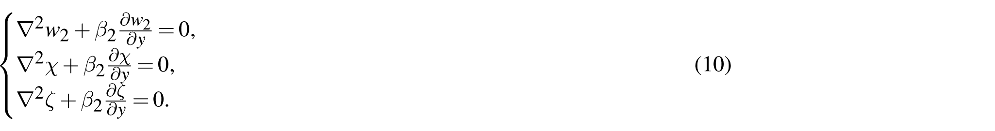
Defining auxiliary functions χ and ζ as

Equation (4) reduces to
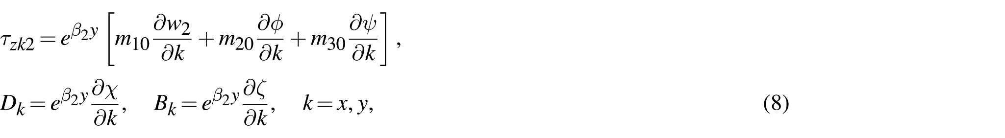
where

It is clear from Figure 1 that the considered geometry is symmetric about the y-axis. Consequently, it suffices to take into account the region

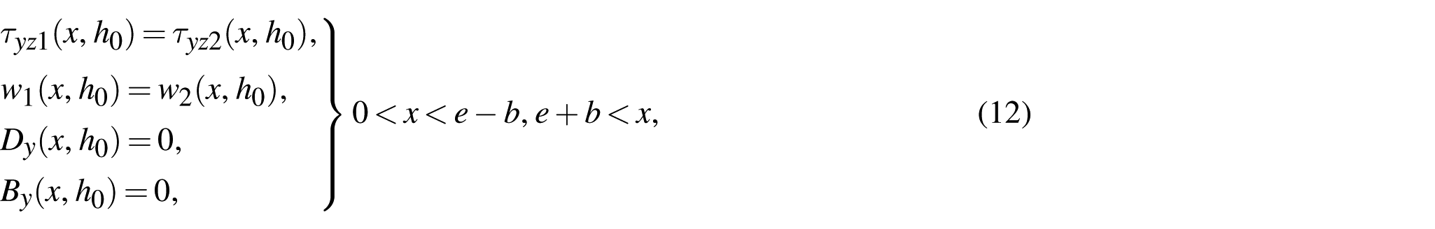
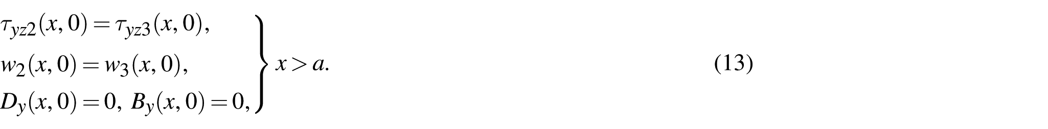
The continuity conditions about the interfaces are as follows
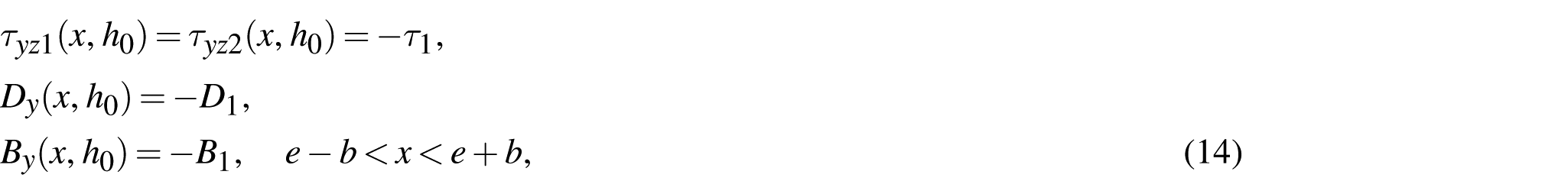
Conditions on the magneto-electrically impermeable crack surfaces are given by


3. Mathematical analysis
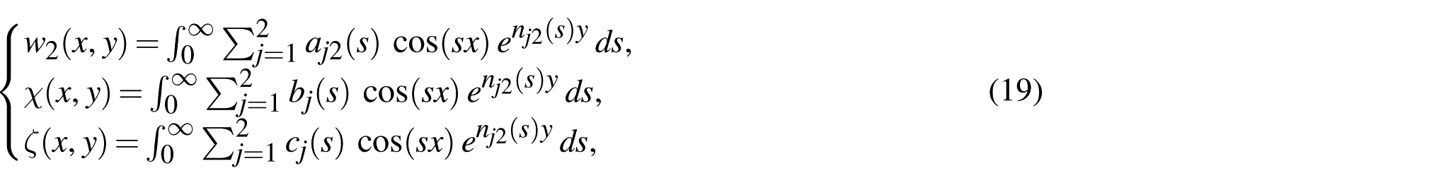
Equations (9) and (10) using the Fourier cosine transformation with regard to x yield
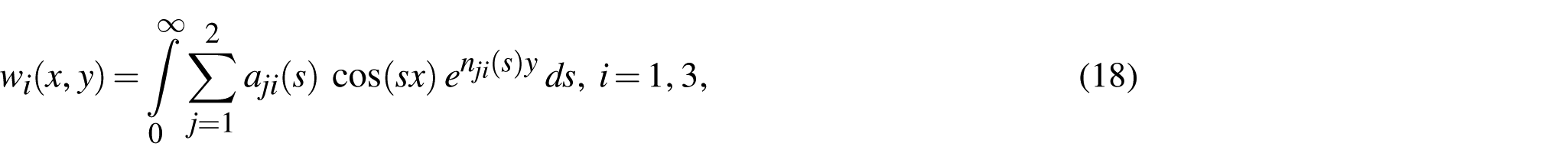
where
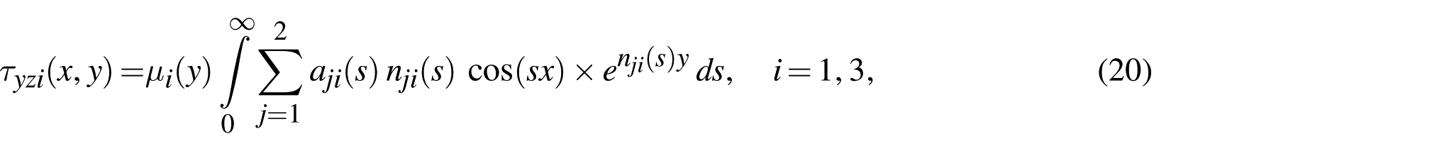
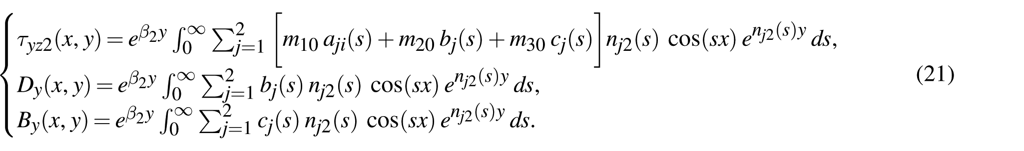
and for the FGMEE strip (2), equations (8) and (19) give the expressions of anti-plane shear stress, in-plane electric displacement, and magnetic inductions as
Defining new functions as
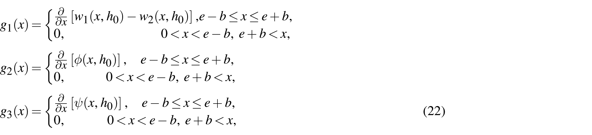
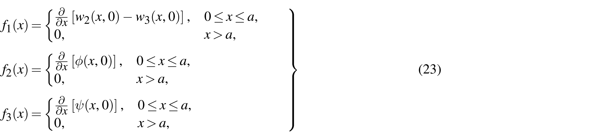
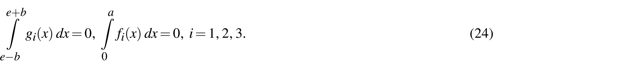
that under the following conditions
From equations (11) to (13) and (20) to (23), 10 equations are found that have the following matrix form
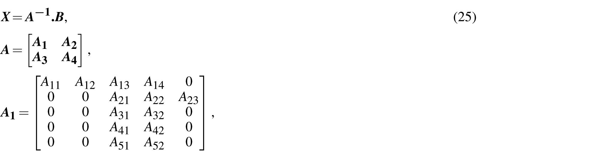
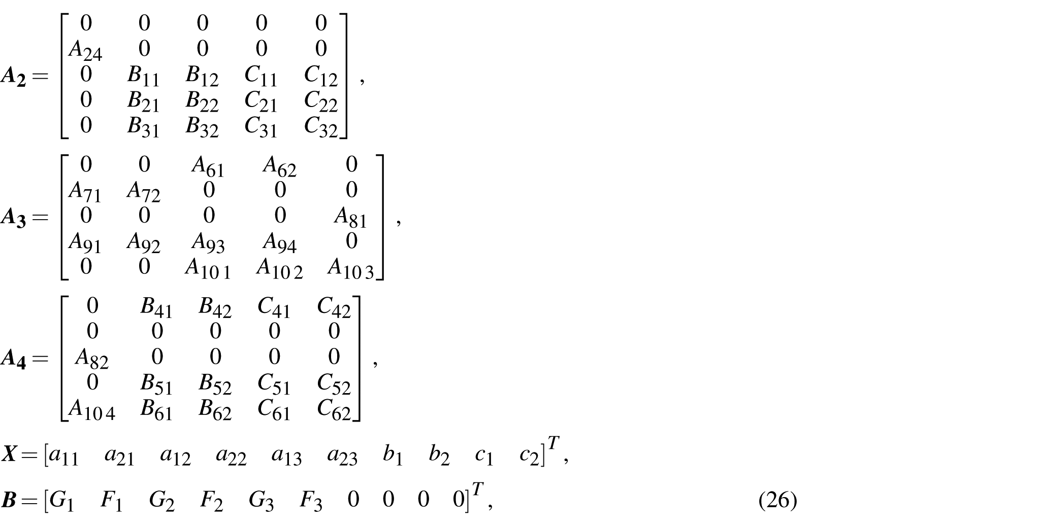
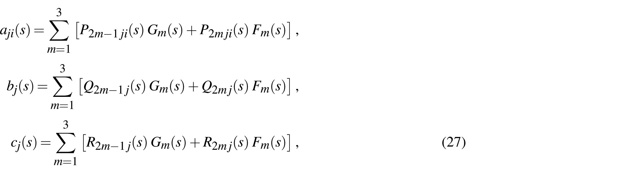
where
where
3.1. Numerical solution
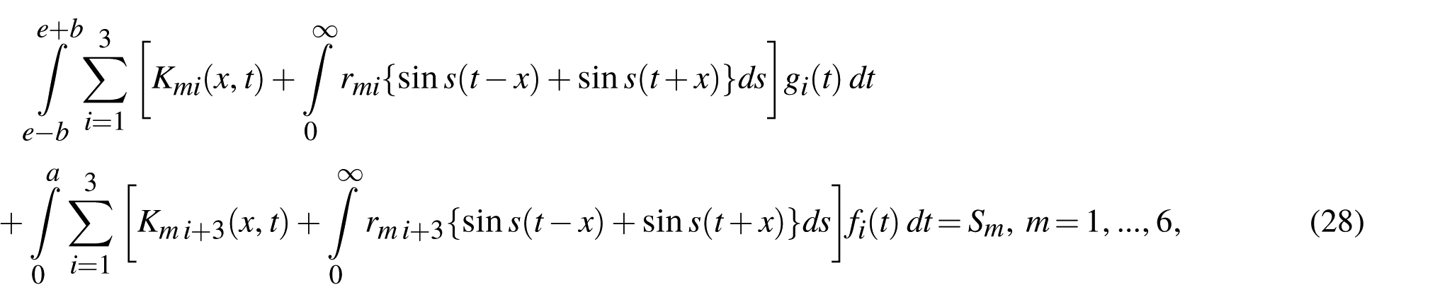
Equation (28) is solved numerically using a truncated series of Chebyshev polynomials of the first kind [5] as a result of the complex nature of the kernel that emerged in the set of singular integral equations
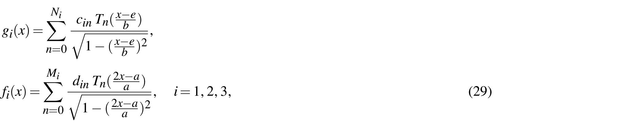
where

where
4. Driving force parameters
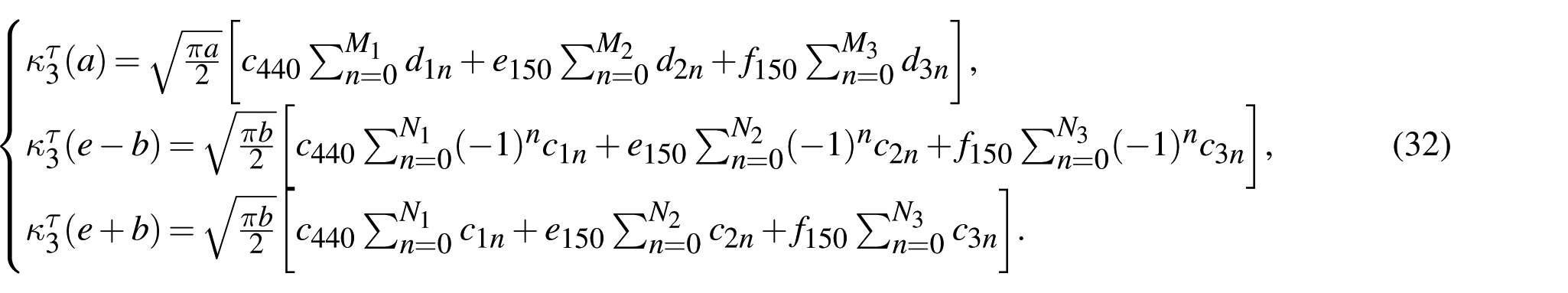
The expression for the stress intensity factor (SIF)
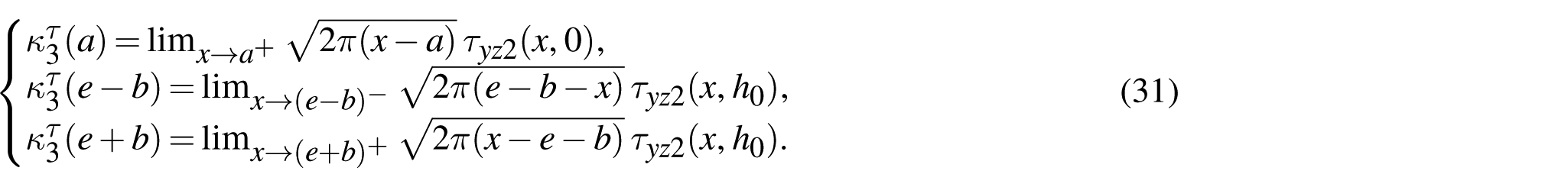
In terms of
Note that the present analysis is based on the framework of linear elasticity and linearized constitutive relations, under which the classical
5. Numerical outcomes and discussion
Here, the effect of strips’ width ratio, non-homogeneity parameter ratio, interfacial crack length ratios, and applied magnetic-electric loadings on the normalized SIFs is shown. For calculation purpose,
5.1. Verification
A verification to compare the found results of this study with [15] is done in this section. For thickness of FGM strip (1) tends to zero,
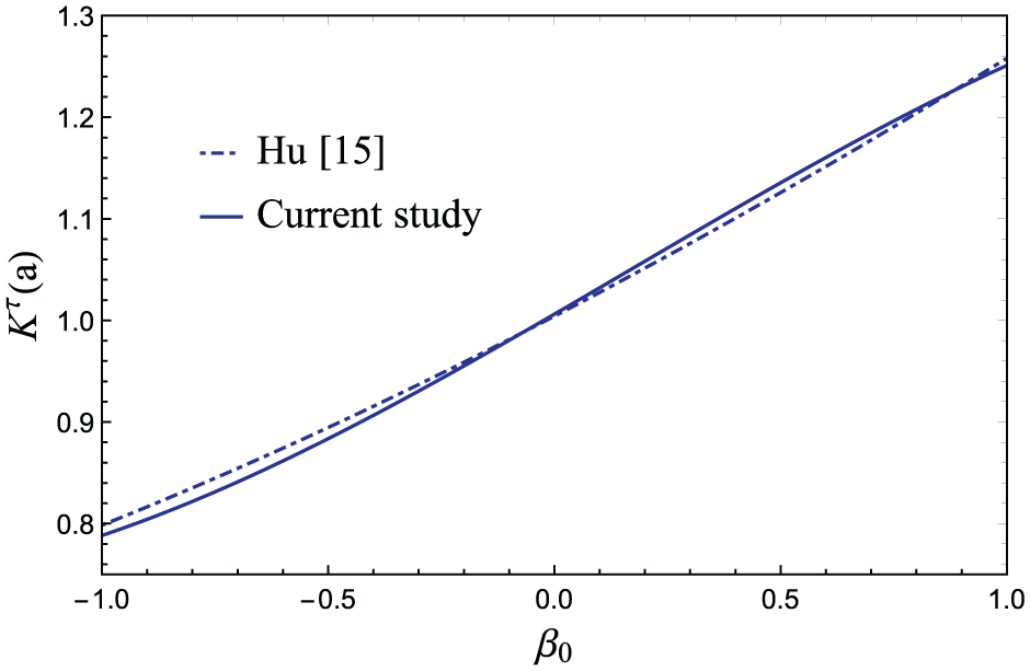
Comparison of this study with the work by Hu and Chen [15].
5.2. Effect of strips’ width ratio
Figure 3 illustrates how the width of strips affects the likelihood of crack initiation. It is detected from the figure that with the increasing width of strips, the normalized SIF at all the crack tips started to decrease. In other words, the fracture initiation likelihood decreases.
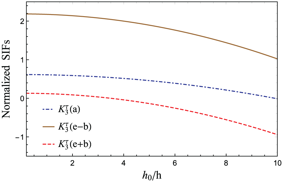
Effect of strips’ width ratio on normalized SIFs at the offset interfacial crack tips
By increasing the strips’ width, the influence of boundary constraints reduces. This redistributes the coupled stress fields over a larger region and lowers stress concentration near the crack tips.
Therefore, it can be said that by considering thicker FGM strips crack-tip driving forces in terms of SIFs, cracks can be reduced.
5.3. Effect of non-homogeneity parameter ratio
The influence of non-homogeneity parameter ratio
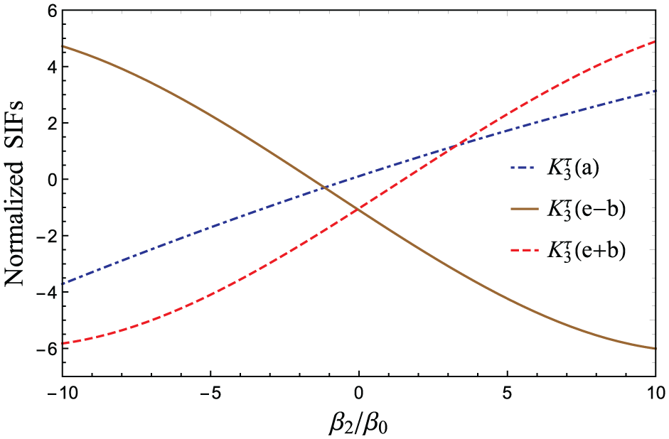
Effect of non-homogeneity parameter ratio on normalized SIFs at the offset interfacial crack tips
Thus, upon examination of the results, it can be concluded that for negative values of the non-homogeneity parameter ratio, the crack-tip driving forces in terms of SIFs of the central crack are less compared to the positive ones. Whereas for the offset crack of length
5.4. Effect of interfacial crack length ratios
&
Figures 5 and 6 demonstrate how the interfacial crack lengths affect the fracture initiation likelihood of cracks.
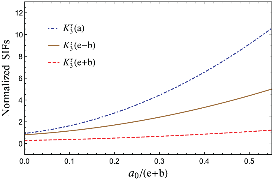
Effect of central crack length variation on normalized SIFs at the offset interfacial crack tips
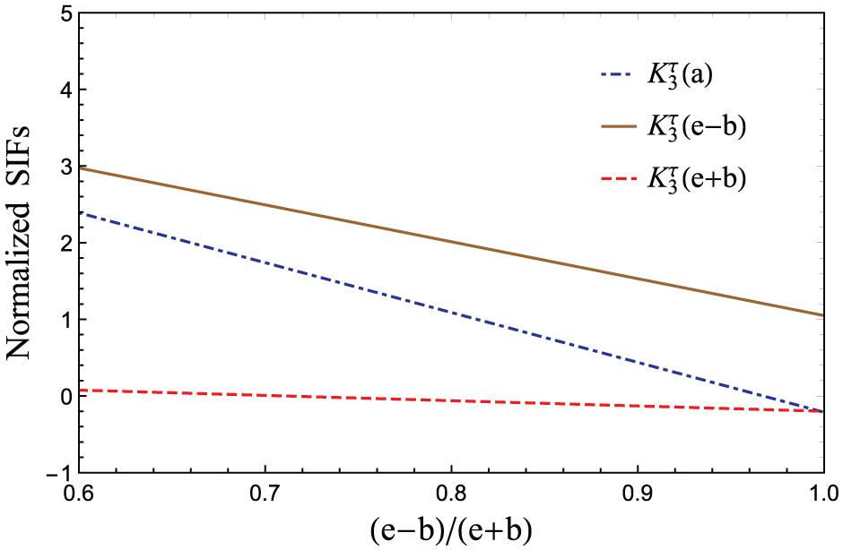
Effect of offset parallel crack length variation on normalized SIFs at the offset interfacial crack tips
It is clear from Figure 5 that the normalized crack-tip SIFs began to rise if the length of the central crack
Similarly, Figure 6 shows that if the length of the central crack is fixed, i.e.,
In other words, when offset cracks are located close to each other, strong crack-interaction effects arise due to stress and coupled-field disturbances. This interaction amplifies the intensity of stress near the crack tips and thereby accelerates crack initiation. It increases the probability of interfacial failure.
Therefore, it may be inferred that the likelihood of crack initiation increases as the central and offset parallel cracks approach one another.
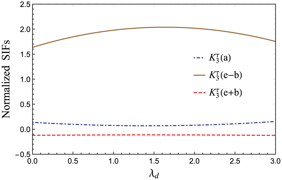
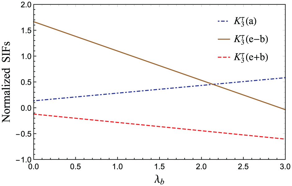
5.5. Effect of electric
and magnetic
loadings
The influence of electric and magnetic loadings is depicted in Figures 7 and 8.
Effect of electric load
Effect of magnetic load
According to Figure 7, maintaining the magnetic load unchanged, if the electric load increases, then
On the other hand, the fracture initiation likelihood of offset parallel cracks decreases for fixed electric load and increasing magnetic load, but increases for the central crack. It shows that normalized SIFs are significantly impacted by both electric and magnetic loads.
The magnitude and nature of the applied electric and magnetic loadings affect the crack-tip SIF by either increasing or decreasing, as per the load nature. Therefore, electromagnetic loading conditions play a significant role in the fracture stability and reliability of the considered layered structures.
6. Concluding remarks
The influence of geometrical and material factors on the offset interfacial type cracks placed in an FGMEE-FGM layered composite under the multiple loading of in-plane magnetic, electric, and anti-plane mechanical kinds is analyzed in this article. The approach employed includes the integral transformation technique and Chebyshev polynomials. Moreover, the findings of the present investigation are also verified. The following are some major findings of this study.
The analytical expression of SIF close to the crack tips is attained with the utilization of Chebyshev polynomials.
As the width of the strips increases, the fracture possibility decreases.
The effect of non-homogeneous graded parameters on normalized SIF at the crack tips is examined, and it is found that the stronger the material properties, the higher is the fracture initiation likelihood of the crack.
The closer the offset interfacial crack tips, the higher the magnitude of normalized SIFs, indicating that the possibility of failure.
Finally, for distinct values of magnetic and electric loads, the normalized SIFs have a varying nature. Thus, the effect of magnetic and electric loads on the fracture initiation likelihood of cracks cannot be neglected.
Footnotes
Appendix 1
Funding
The authors received no financial support for the research, authorship, and/or publication of this article.
Declaration of conflicting interests
The author declared no potential conflicts of interest concerning the research, authorship, and/or publication of this article.
Availability of data and materials
Not applicable.