
Abstract
Tomographic image reconstruction has a wide variety of applications ranging from engineering applications to medical applications. Algebraic reconstruction methods, used to obtain the solutions of tomographic image reconstruction problems, are very slow in nature. This performance bottleneck has been discussed in detail in the present work. This paper encompasses a parallel (multi-processor based and multi-processor multi-GPU based) single-view coded multiplicative algebraic reconstruction technique. It has been found that parallel implementation of this algorithm helps in removing the performance bottleneck without compromising with quality of reconstruction. It has been also found that if one uses four processors to reconstruct an image of 512 × 512 × 512 volume size, then the multi-processor based algorithm takes 1997 s to perform one swap of 200 projections taken over a span of 360°. The use of four processors leads to an increase in speed of 2.39 in comparison with a single processor. Further, the proposed multi-processor multi-GPU based algorithm takes 186 s to perform the same reconstruction by using four GPUs, resulting in an increase in speed of 25.7 in comparison with a single processor. We are able to process 42 projections per minute by using the multi-processor multi-GPU based algorithm. The algorithm is applicable to online laminographic applications.
Keywords
1. Introduction
Nondestructive testing plays a vital role in material characterization. It is also very useful in engineering as well as in medical applications. Tomographic image reconstruction is one of the available nondestructive testing techniques. It involves recovering the original object cross section through the projection data obtained. The solution of image reconstruction problems has a variety of options, such as solutions based on transform methods, solutions based on series expansion methods, or solutions based on optimization methods. Transform-based methods are fast and provide good results for full data but these methods gives inferior results when they are used in limiting-view cases. Series expansion-based methods are slow in nature but provide better results in limited-view cases and also with noisy data in comparison to transform-based methods. Optimization-based methods are too slow. The performance bottleneck of image reconstruction algorithms can be removed by their parallel implementation.
The series expansion-based method for image reconstruction was first presented by Gordon et al. (1970) as an additive algebraic reconstruction technique (ART). Kak and Slany (1987) proposed a variation of the additive ART method, which is popularly known as the simultaneous algebraic reconstruction technique (SART). Mishra et al. (1999) presented a further variation, i.e. the multiplicative algebraic reconstruction technique (MART). The latter has been used for temperature profile generation. Jain et al. (2011) have shown that three-dimensional (3D) image reconstruction based on the MART algorithm requires huge memory and computation time. They have reported the reconstruction of 128 × 128 × 128 volume size. A GPU-based parallel algorithm has been proposed by Bajpai et al. (2012) for two-dimensional (2D) image reconstruction.
A serial single-view coded MART has been described by Bajpai et al. (2013). In this paper, the parallelization of this algorithm is presented on two platforms. The other series expansion based algorithms available in literature are presented in [7-16] along with CUDA programming methodology. First, an efficient parallel algorithm on a multi-processor platform is presented in Section 4, then we propose an algorithm for a multi-processor multi-GPU platform in Section 5. The test object is described in Section 6, while the experimental results have been analyzed and discussed in Section 7.
2. Principle of computed tomography
If M is the total number of rays in all projections obtained from scanners and N is the total number of voxels in the grid with N >> M, then the equation for the image reconstruction from projections can be written in the following form
where ϕ is projection data and W is a matrix of order M×N containing the weight wij for each voxel. The vector f (vector of unknowns) is a column vector storing the image to be reconstructed and e represents stopping criteria.
We can write equation (1) in an expanded form as a system of linear equations:

The weight, wij, represents the contribution of the ith ray of a projection view to the jth voxel of the object cross section. It is clear that the weights bear a crucial role in the solution of this system of equations. Weight wij accurately represents the influence of a voxel fj on a ray ri passing through pixel pi, as shown in Figure 1.
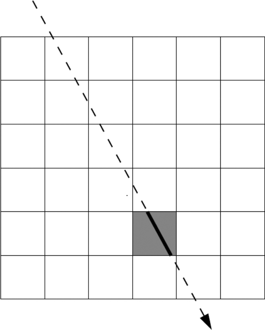
Ray passing through object cross section.
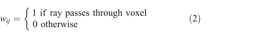
The value of wij is geometry dependent and can be calculated with the help of the scan geometry parameters, e.g. source to detectors distance, source to object distance, fan/cone angle, etc. The approach which has been used to calculate the weights is based on the following idea. If the rith ray passes through the pith pixel, then the corresponding weight wij is 1, but otherwise is 0.
This enables us to use sparse matrix storage techniques to store the weight matrix and reduces the memory requirement for the weight matrix storage.
The number of unknowns is not the same as the number of equations. It should be noted that the system of linear equations obtained from the tomography is highly ill-posed and ill-conditioned. This system is under-determined in nature and hence has infinitely many solutions. Ill-posed condition implies that we cannot use direct methods for solving system of linear equations. This system of linear equation is highly sparse in nature. There exist many sparse solution techniques which can be used to solve this system of equations. The most popular ones that can be used are the conjugate gradient method, Moore–Penrose generalized inverse, and least square method. These methods may not be able to provide the desired results in reasonable time. This leads to the problem of designing an appropriate method which can be used to solve the tomographic problem. The additive algebraic reconstruction method (Gordon et al., 1970) is one such method which can be used to solve the system of linear equations obtained from the tomographic reconstruction problem. This is an iterative method which starts with an initial guess and then a correction term has to be calculated and is incorporated with the field values of the object cross section. This process is repeated until the stopping criterion has been achieved. Major steps of these algebraic methods can be described as follows:
Initialize the pixel values.
While a convergence criterion has not been fulfilled:
Calculate the correction term.
Update the pixel values accordingly.
3. Serial single view MART (SvMART)
The algorithm has been discussed in detail elsewhere (Bajpai et al., 2013). Here, we are summarizing it for clarity. Let S be a set of rays: S ={I1, I2, I3, …, IM}. The set S has been divided into p equal-sized subsets s1, s2, s3,…, sp in such a way that s1={I1, I2,…, It}, s2={It+1, It+2,…, I2t} and so on where t = M/p and p is the total number of projection views. SvMART states that only one subset has to be taken into consideration for reconstruction at a time and output of this subset works as input for the next subset.
Major steps of SvMART are given below for a particular iteration:
4. Multi-processor based parallel SvMART (P-SvMART)
This section describes a parallel version (multi-processor based parallel implementation) of the SvMART algorithm. The algorithm, SvMART, can be divided in three parts: (a) generation of weight matrix, (b) computation of correction term, and (c) field value update. The weight matrix is geometry dependent and depends on the scanning parameters used to obtain the projection data. The scanning parameters are the same for a particular projection view. The individual ray of the particular projection view can be uniquely identified with the cone angle and the other parameters used. This indicates that the weights obtained from individual rays can be calculated simultaneously for a particular projection view. This phenomenon indicates the parallelism within a block of rays (projection view).
Each ray has its own correction term to the field values depending on its contribution to the particular pixel of the object grid. Further, each ray can be uniquely identified by the combination of scanning parameters. This fact results in parallelism within the block of rays (projection view). It enables us to distribute the bunch of rays to different processors and to execute the algorithm on this set of rays. This approach may lead to concurrent write situations as more than one ray of a projection view can pass through a particular voxel and, hence, it needs to update the field value of that voxel. This fact indicates that the third step of the SvMART algorithm has to be performed sequentially.
The major steps of parallel SvMART can be described as follows.
4.1. P-SvMART
This section discusses the parallel SvMART algorithm for cone beam geometry over circular scanning trajectory. Let us assume that each projection view has Nray number of rays and there are N processors available for parallel implementation. Let us assume that S is a set of total number of rays present in a projection view such that:
where
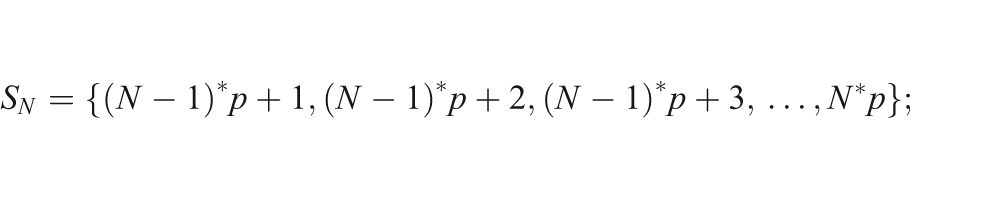
where p=
4.1.1. Weight matrix generation
The weights can be calculated with the help of scanning parameters, which are the total number of projection views (Npa), the total number of rays in each projection view (Nray), the total number of voxels in each side of the object grid (Npix), the distance between the source and object center (Scob), the distance between the source and detector (Scd), the distance between two detector pixels (d), and the span over which projection data has been collected. We use one-to-one mapping for allocation of subsets of set S to the processors. Each processor calculates the weight of each ray belonging to the subset assigned to it. These weights will be further used for calculation of correction terms.
4.1.2. Correction term computation
The weights obtained from Step a have been used to calculate the correction term. Each ray has its own correction term and this calculation is independent from other rays. We will use one-to-one mapping for processor assignment for this step also. The algorithmic step can be written as:
4.1.3. Field value update
The correction term of a ray calculated in Step b represents the effect of that particular ray on the voxels through which it is passing. It is clear that this step involves write operations on the object field value; hence, this step will be performed sequentially. It can be stated as follows:
5. GPU-based parallel SvMART (G-SvMART)
This section describes a multi-processor multi-GPU based parallel algorithm for high resolution image reconstruction. As in the previous section, we have implemented the first two steps of the SvMART algorithm in a GPU environment. One-to-one mapping has been used to invoke the processors and GPUs. Operations have been performed on GPUs and results of this execution have been returned to processors and finally the field values have been updated. Major steps of this algorithm can be stated as being the following.
5.1. Weight matrix generation
It has already been reported that each ray belonging to a projection view can be uniquely identified with the help of scanning parameters. Let us assume that there are Nslice detector rows each having Ndet detector elements. This means there are Nslice*Ndet numbers of detector elements. Let us assume that we are using M GPUs. We are using one-to-one mapping hence M processors have been invoked. Each GPU will calculate the weights for Nslice*Ndet/M number of rays.
5.2. Calculation of correction term
The correction term of each ray has been calculated by GPUs. These correction term values have been then transferred to a CPU for further action. The weights are used for calculation of correction term as follows:
5.3. Update of field value
This step has been performed on the CPU side and the updated field values have been sent to the GPU for further execution of another projection. It can be stated as follows:
6. Test object
The center slice of a numerical phantom (slice number 256) from different planes (e.g. XY, YZ, and XZ planes), which is been shown Figure 2, has been used for testing of the algorithm. Geometrical resolution properties have been achieved by smooth change in density function of the phantom. The contrast resolution properties have been shown by small lines representing the defect in numerical phantom.
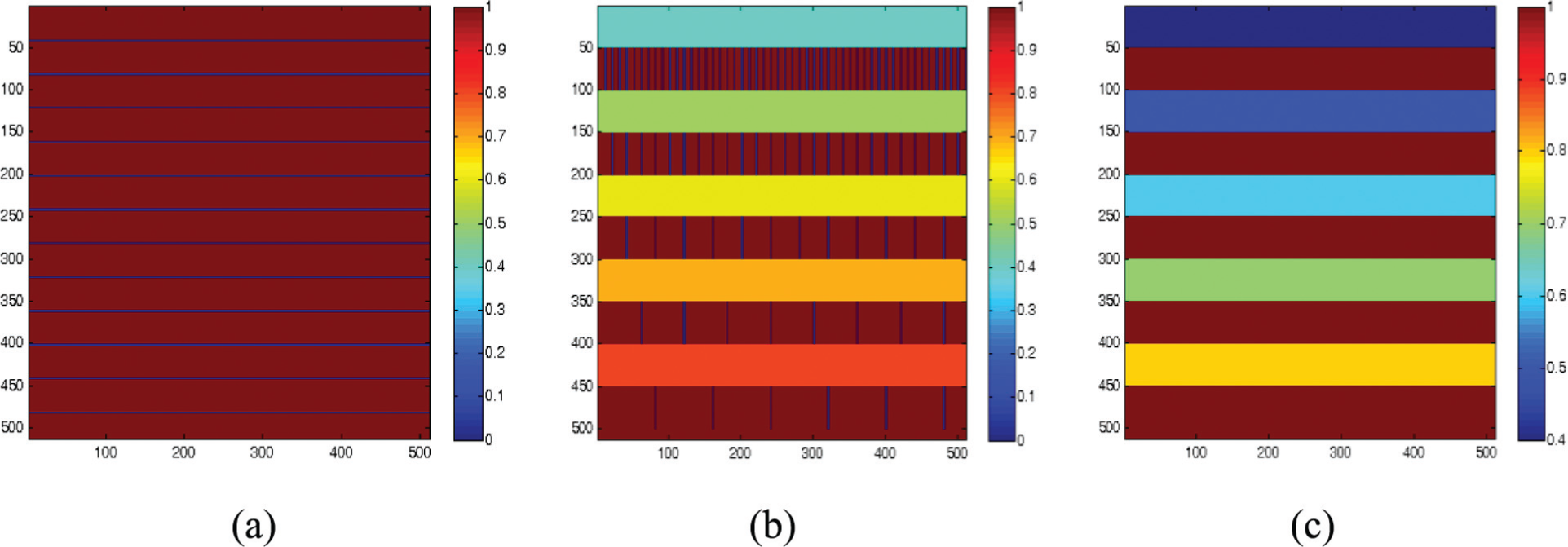
Original images of numerical phantom at (a) XY plane, (b) YZ plane, and (c) XZ plane of slice number 256.
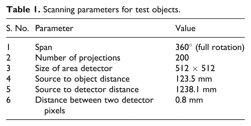
A cone-beam scanning geometry over a circular trajectory has been used to scan the object, as shown in Figure 3. It has been assumed that the object is fixed and that the source detector system is rotating in the system, as illustrated in Figure 3. The detector measures the X-ray flux over a plane. The cone beam data collection methodology enables us to collect the projection data for 3D image reconstruction in the same time interval taken by a conventional fan beam system for its 2D reconstruction. This implies that the main advantage of a cone beam algorithm is the reduction in data collection time. Parameters shown in Table 1 have been used for the generation of projection data. The numerical phantom described above with different resolutions has been used to check the accuracy and improvement in processing speed of the algorithm.
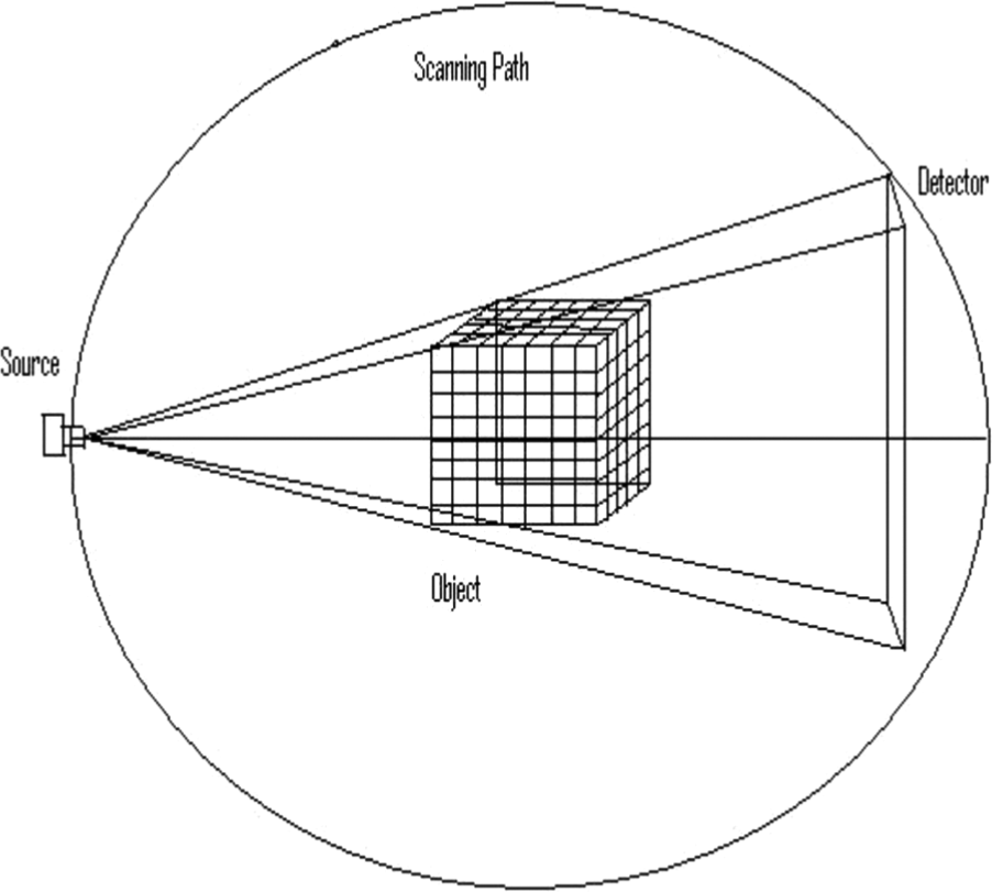
Cone-beam projection data measurement.
Scanning parameters for test objects.
All these algorithms have been implemented on two SL 390 G7 4U half width servers provided by HP. The SL 390 G7 4U half width server tray supports a low profile x8 gen2 PCI-e slot, while also supporting eight internal x16 gen2 slots dedicated for eight GPUs. The server has 16 in total Tesla M2070 GPU cards.
7. Results
The algorithm has been tested on a numerical phantom. The results obtained are very encouraging and are described in detail in this section.
7.1. P-SvMART
The numerical phantom is scanned using the parameters shown in Table 1. Execution times in seconds with different numbers of processors are given in Table 2. It has been found that parallel SvMART takes 4781 s for one swap of 200 projections on the SL 390 G7 sub-cluster for a reconstruction of 512 × 512 × 512 volume size.
Execution time for single iteration of P-SvMART with different number of processors.
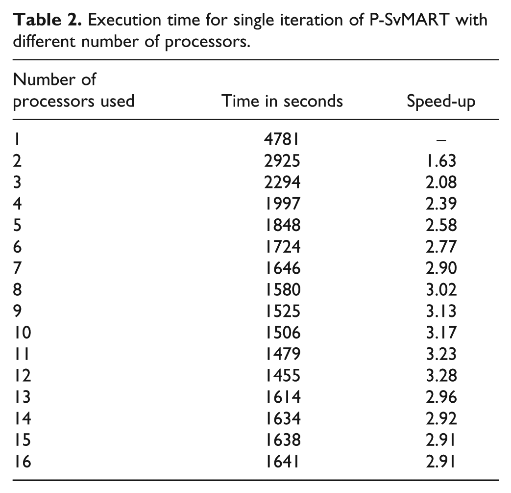
P-SvMART takes 2925 s to execute a single iteration with two processors. This indicates that we obtain an improvement in processing speed of more than 1.5 times if we increase the number of processors from one to two. This improvement rises to 2.4 times if the number of processors used is four. It can be seen from Table 2 that we do not obtain much further improvement in processing speed by increasing the number of processors.
A graph of execution time against the number of processors is shown in Figure 4. It has been found that the slope of the curve is almost flat for the number of processor lying between 4 and 12. This indicates that no further improvement in processing speed is achieved if the number of processors is greater than 4. It has also been found that the execution time increases if the number of processors is greater than 12. The increase in execution time, by using the number of processors greater than 12, is a result of higher communication cost associated with the reconstruction of an image of 512 × 512 × 512 size as compared to computation cost.
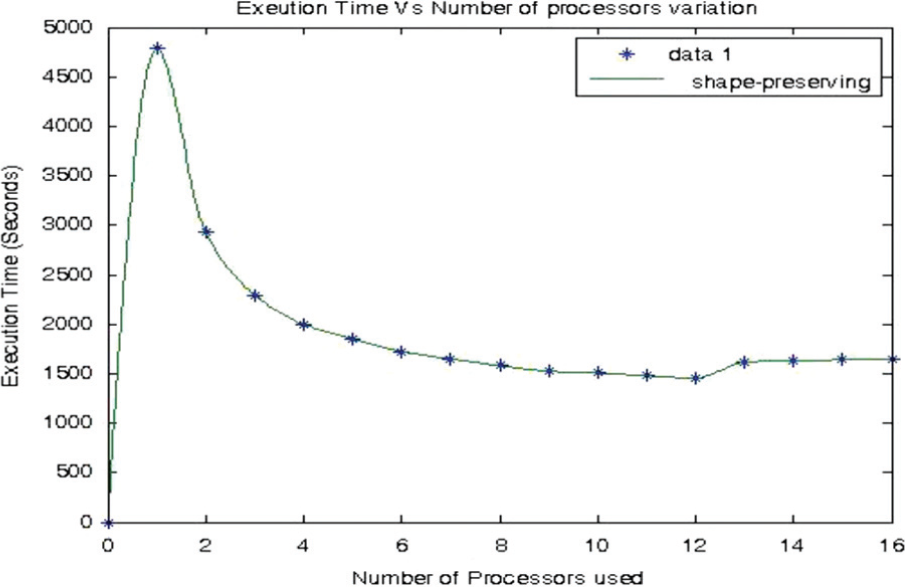
Execution time (seconds) variation with increasing number of processors.
Figure 5 shows the reconstructed images of the XY, YZ, and XZ planes of slice number 256 of the numerical phantom obtained using a single processor. The value of relaxation parameter for this study was chosen as 0.3. The corresponding reconstructed images with two processors are shown in Figure 6. The value of the relaxation parameter was the same as for a single processor, i.e. 0.3. It has been found that without compromising with the quality of reconstruction we have obtained an improvement in processing speed of more than 1.5 times by using two processors instead of one. The quality of reconstruction is the same as that with a single processor while increasing the number of processors used.
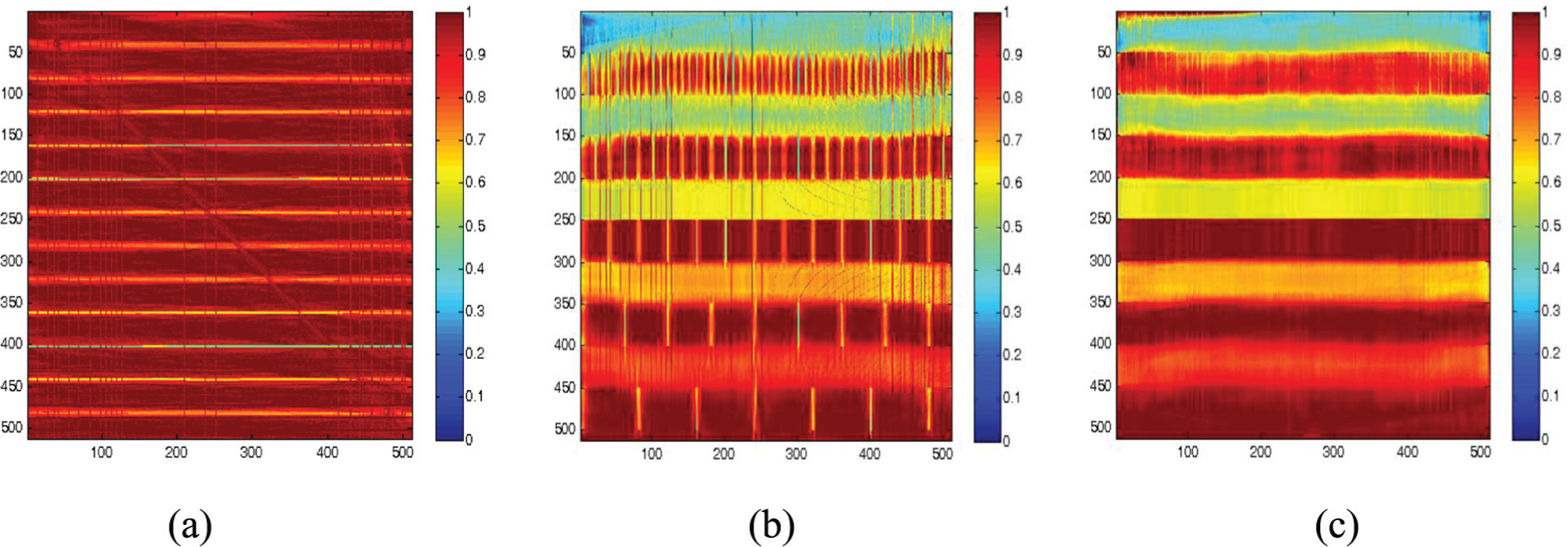
Reconstructed images of numerical phantom at (a) XY plane, (b) YZ plane, and (c) XZ plane from slice number 256 with single iteration using one processor.

Reconstructed images of numerical phantom at (a) XY plane, (b) YZ plane, and (c) XZ plane from slice number 256 with single iteration using two processors.
7.2. G-SvMART
The execution times obtained from G-SvMART are shown in Table 3. It has been found that it takes 282 s to execute a single iteration for reconstruction of a 512 × 512 × 512 volume size with 200 projections. This clearly indicates that we have obtained an improvement in processing speed of around 17 times in comparison of P-SvMART. It takes 232 s when two GPUs have been used. This execution time also includes the CPU–GPU memory transfers.
Execution time for single iteration of G-SvMART with different number of processors and GPUs used.
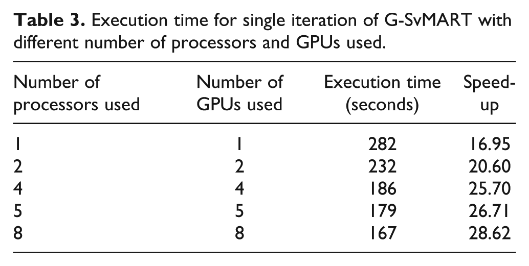
Figure 7 shows a pictorial diagram of execution time vs. number of GPUs used. We can see from Figure 7 that we are not obtaining much further improvement in processing speed by increasing the number of GPUs more than five.
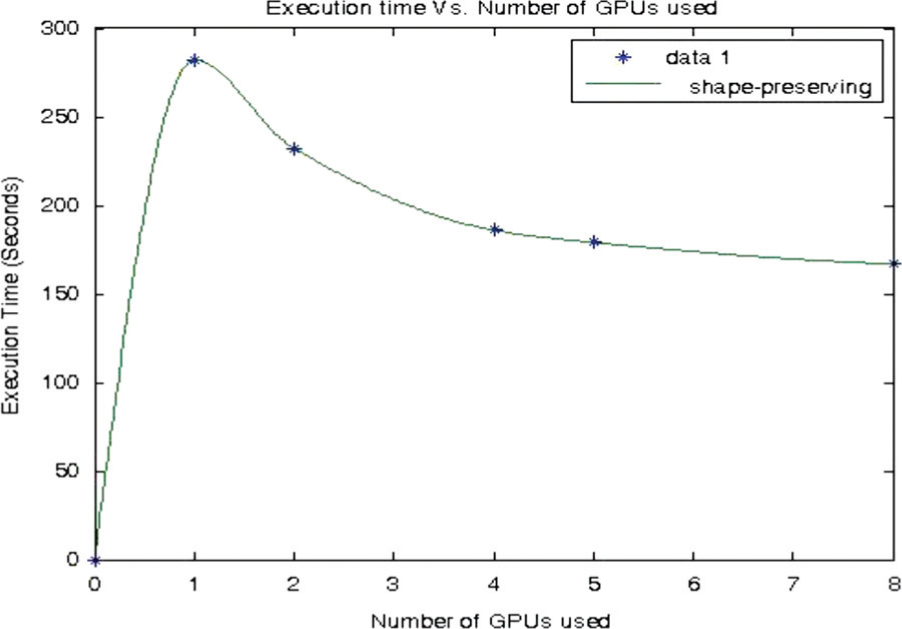
Execution time vs. number of GPUs used for G-SvMART.
Figure 8 shows the reconstructed images of XY, YZ, and XZ planes of slice number 256 with single iteration using a single GPU. G-SvMART provides fast results and the quality of reconstruction is comparable to PMP-SvMART. This algorithm enables us to perform high resolution image reconstruction in real time.
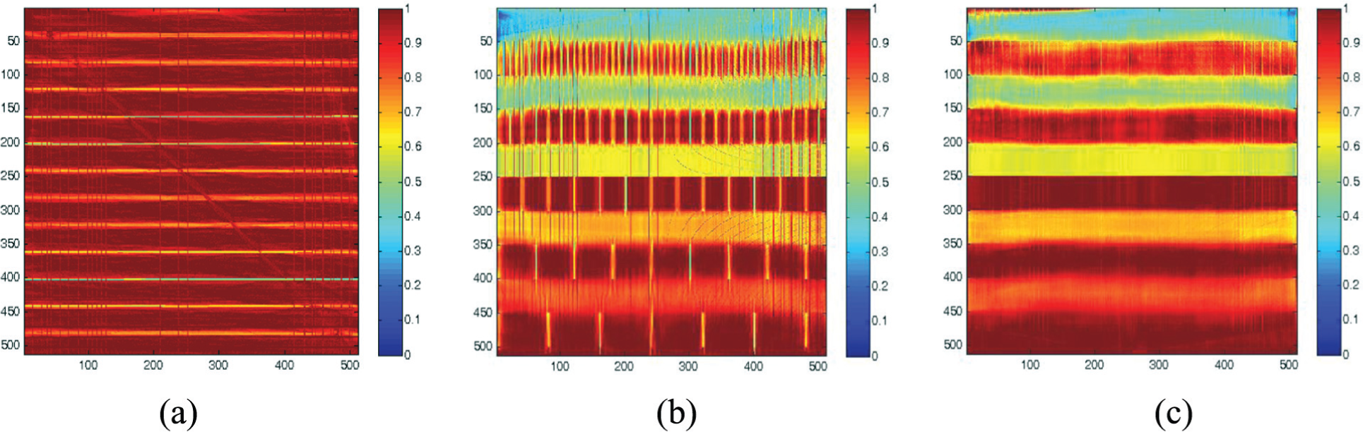
Reconstructed images of numerical phantom at (a) XY plane, (b) YZ plane, and (c) XZ plane from slice number 256 with single iteration using one GPU by G-SvMART.
8. Conclusions
This paper has presented an efficient parallel algorithm of tomographic inversion for 3D image reconstruction. The algorithm has been implemented on multi-processor and multi-GPU based systems. Using P-SvMART, which is the algorithm for multi-processor applications, an improvement in processing speed of around 1.5 has been achieved by increasing the number of processors from one to two. This improvement rises to 2.4 times for four processors for 512 × 512 × 512 volume size reconstruction from 200 projections. It enables reconstruction in 1997 s for the above volume size with four processors.
The GPU-based algorithm G-SvMART enables the reconstruction of 512 × 512 × 512 volume size with 200 projections in 282 s on a single GPU. It enables processing of around 7 projections every 10 s. This implies that we can process 42 projections per minute. The scanning time for the above volume size object is greater than the reconstruction time. This means we can make use of G-SvMART for online reconstruction.
Footnotes
Funding
This research received no specific grant from any funding agency in the public, commercial, or not-for-profit sectors.
Author biographies
Manish Kumar Bajpai is currently working as Assistant Professor in the Department of Computer Science & Engineering at Indian Institute of Information Technology Jabalpur (IIIT Jabalpur), Jabalpur, India. He received his Doctoral degree from Indian Institute of Technology Kanpur, India in 2013. He is currently working in areas of high performance computing, image reconstruction and climate change.
Phalguni Gupta received the Doctoral degree from Indian Institute of Technology Kharagpur, India in 1986. Currently he is a Professor in the Department of Computer Science & Engineering, Indian Institute of Technology Kanpur (IITK), Kanpur, India. He works in the field of biometrics, data structures, sequential algorithms, parallel algorithms, and image processing. He is an author of two books and 12 book chapters. He has published more than 250 papers in international journals and at international conferences. He is responsible for several research projects in the area of biometric systems, image processing, graph theory, and network flow. Prior to joining IITK in 1987, he worked in Space Applications Centre Ahmedabad, Indian Space Research Organization, India.
Prabhat Munshi is a Professor of Mechanical Engineering at IIT Kanpur and in also associated with the nuclear engineering graduate program. The major areas of his interest are computerized tomography, non-destructive testing, non-invasive measurements, and nuclear reactor safety analysis. He has worked for Commonwealth Edison Company (Chicago), Fraunhofer Institute for Nondestructive Testing, and The Royal London Hospital. He has been an Alexander von Humboldt fellow at Leibniz University, Kassel University, and Saarland University. He is a fellow of the Indian National Academy of Engineering.