
Abstract
Data volumes are exploding as sensors proliferate and become more capable. Edge computing is envisioned as a path to distribute processing and reduce latency. Many models of Edge computing consider small devices running conventional software. Our model includes a more lightweight execution engine for network microservices and a network scheduling framework to configure network processing elements to process streams and direct the appropriate traffic to them. In this article, we describe INDIANA, a complete framework for in-network microservices. We will describe how the two components-the INDIANA network Processing Element (InPE) and the Flange Network Operating System (NOS)-work together to achieve effective in-network processing to improve performance in edge to cloud environments. Our processing elements provide lightweight compute units optimized for efficient stream processing. These elements are customizable and vary in sophistication and resource consumption. The Flange NOS provides first-class flow based reasoning to drive function placement, network configuration, and load balancing that can respond dynamically to network conditions. We describe design considerations and discuss our approach and implementations. We evaluate the performance of stream processing and examine the performance of several exemplar applications on networks of increasing scale and complexity.
Keywords
Introduction
As the volume and velocity of data increase at the edge, it is driving the need for high-performance data processing at microsecond speeds. Data analytics applications are moving away from monolithic architectures and toward a microservices architecture, due to the flexibility and elasticity provided by this model (Bucchiarone et al., 2018; Ortiz et al., 2022). Other types of applications demand low-latency processing for responsiveness. Both of these trends are motivating a far more distributed computational architecture, with a continuum of computing resources from the Cloud to the Edge (Asch et al., 2018). Our goal in the realization of this computing continuum is in providing in-network processing elements that allow the maximum articulation of processing element distribution for most efficient placement.
Virtualization is the most common method of sharing physical hardware resources for deploying microservices. Today, it is important to create a platform to share the same physical resources to deploy and service multiple incoming data streams so that interactive real-time applications can meet tight latency requirements. Currently, abstractions to deploy microservices include several hypervisor and container-specific solutions. However, multiple layers of virtualized physical resources, operating system kernels, and network packet processing immensely limit the infrastructure’s ability to attain sub-millisecond latencies for critical services (Cooke and Fahmy (2020); Jha et al., 2021). Recent research has focused on networking infrastructure components that are underutilized despite being highly available in today’s data centers (Choi et al., 2020; Ibanez et al., 2021). Specifically, programmable networking components such as programmable Smart NICs and high-speed switching ASICs, processors and FPGAs are recent additions to the data processing ecosystem as strategies to introduce new packet processing protocols and management with ease. In addition to packet processing, these programmable components are now considered an attractive alternative to running specific network services for use cases such as consensus, packet classification, and deploying microservices (Choi et al., 2020; Dang et al., 2020; Ibanez et al., 2021; Kohler et al., 2018). With significant data processing capabilities, these components can lay the ground for achieving latency requirements for interactive applications.
Building a framework for deploying microservices within the networking domain comes with challenges, including a limited set of resources, sharing resources to facilitate existing networking functionality, and limited infrastructure access. Consequently, most application designers are unaware of how to utilize this high-speed infrastructure and benefit from low-latency application execution, limiting performance improvements to only those experts capable of designing custom solutions (Gupta et al., 2018; Jepsen et al., 2018; Kohler et al., 2018; Xiong and Zilberman, 2019; Zheng and Zilberman, 2021). The microservice framework also needs to support 1) service isolation, 2) elasticity, 3) stream and service scheduling, and 4) dynamic service deployment. Throughout this paper, we discuss considerations in achieving the characteristics above while discussing our proposed solutions. In addition, we also discuss the limitations of employing a low-level framework for deploying microservices.
At the lowest level, deploying microservices requires identifying kernels essential to core functionality and creating task graphs for different applications. Examples of applications include high-performance computing, the Internet of Things (IoT), and graph processing applications. Common characteristics of these streaming applications include data streaming toward computations, inherently being network-intensive, and having stringent latency requirements. Further, we discuss how we dynamically build task graphs and manage streams based on network properties once these applications are live. In this paper, we present the In-Network Distributed Infrastructure for Advanced Network Applications (INDIANA) for deploying microservices with demanding latency requirements.
The INDIANA framework requires two core components, (1) a stream operator deployment architecture built using RISC-V soft cores, and (2) a flow-oriented network operating system built around a declarative language for expressing network behavior through broad policies. In the implementation provided herein, we leverage components from our prior work, NetFaaS (Ossen et al., 2022) and Flange (Musser et al., 2019), expanding on each and integrating them into a single unified whole. NetFaaS provides the NIC-CPU infrastructure to deploy network functions. These functions run on RISC-V soft cores, which form the baremetal platform. Flange coordinates the necessary stream forwarding and dynamic function placement once the streaming applications are operational. Flange provides essential autoscaling and scheduling features required by NetFaaS by programming SDN-capable switches with network rules, primarily to provide undisrupted services to data streams (modeled as flows). We further discuss our design and implementation in detail in the upcoming sections and present benchmarking results.
In Sections 2 and 3, we discuss our approach to building a baremetal, network-based framework with two core design elements, the network platform created using RISC-V soft cores and the flow-based scheduler implemented with network policies. Section 4 presents our evaluation of the work, while we discuss limitations and future work in Section 5. We provide related work in Section 6. Lastly, we conclude our work in Section 7.
High-Level Design
INDIANA is a framework for deploying microservices in programmable networking devices. We utilize both programmable data and control planes to achieve a fully network-compatible architecture for deploying low-latency services. We focus on interactive applications with demanding low-latency requirements in the IoT domain. Increasingly, applications in this domain require fast analytics to provide a better user experience or perform mission-critical operations for smart infrastructure. We form applications in this space utilizing streaming workloads, where a continuous stream of sensor data comes in, and the workload performs fast computations. Our framework supports building applications using a task graph (§2.1.2), where we deconstruct an application into a group of decoupled services. Each workload characteristic includes (1) being long-running or short-term, (2) event-triggered, and (3) only focusing on a single key functionality. Our Network Operating System (NOS), Flange, provides data flow scheduling across network entities. The schedule is built from fully customizable, user defined, policy programs. In addition to first-class load balancing through intelligent routing, Flange detects changes in network behavior and generates suggested microservice rebalancing plans for INDIANA that react to the new network conditions.
Figure 1 presents the high-level view of INDIANA. Each incoming data stream traverses through a programmable switching fabric towards programmable compute clusters that can be placed anywhere in the edge-cloud spectrum. The programmable switching fabric consists of Software Defined Networking (SDN)-capable switches programmed through Flange. The three key elements, (1) INDIANA Compute Cluster (ICC), (2) Flange, and (3) Service Registry, create the infrastructure to consume incoming stream data and schedule services based on stream flow variations. In a programmable networking device, Flange is synonymous with the control plane, and the ICC is synonymous with the data plane. Flange orchestrates the interactions between data source and compute-performing general routing and load balancing-which we have depicted as the central component between these two elements. Each INDIANA Processing Element (InPE) hosts a set of user-defined operators (InOps) that correspond to high-level streams, are optimized to perform microsecond computations and interact with the networking infrastructure with minimal overhead. Each InPE has ingress and egress networking paths, which it associates via Memory Mapped I/O (MMIO) registers. INDIANA with its programmable compute cluster and Flange component. The left-hand-side of the diagram signifies multiple sensor data sources while the right-hand-side demonstrates core components internal to the cluster.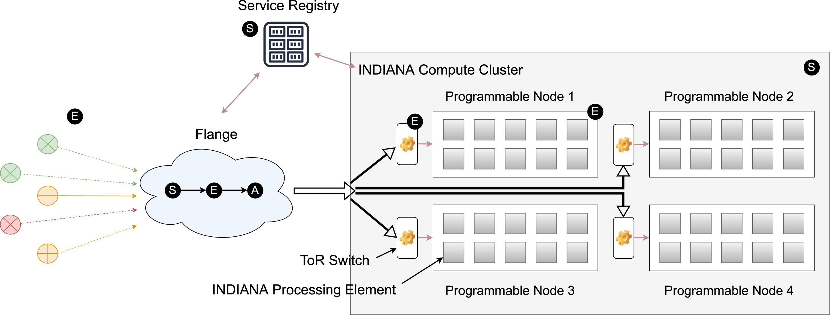
We divide each flow into three ordered stages, (1) Setup, (2) Execute, and (3) Adaptation. INDIANA’s design components each participate in these stages at various times, as indicated by the circled letters in Figure 1.
During the Setup stage, 1. We initialize the ICC with different InPE configurations. We distinguish each processing element by cores of different pipeline depths, instruction issue order, cache sizes, DRAM sizes, and network configurations. 2. On each InPE, we instantiate the desired set of InOps which are associated with their corresponding service identifiers. 3. We register the (InOp, service identifier) pair in the Service Registry. 4. Flange consumes the tuple information from the Service Registry, compiles and builds routing rules, and programs the network switches as necessary for basic initial forwarding.
During the Execute stage, 1. Sensors stream data to the ICC through the network. 2. Packets are forwarded to the correct programmable node by matching the service identifier in the packet. 3. The ToR switch identifies and forwards data stream packets to the correct InPE based on the service identifier. We discuss how we utilize the service identifier to identify the correct InPE in section 2.1.1. 4. The RISC-V core consumes incoming data and completes InOp execution. 5. The switch redirects the final result to the correct destination.
During the Adaptation stage, Flange, 1. Monitors the incoming stream flow. 2. Maps the placement of incoming streams to tiles by labeling (flow, InOp) pairs, organizing pairs by rank, and selecting processing elements with the least utilization in a given tier. 3. Programs the switch with new configurations. The switch now redirects streams to updated cores that can manage the load.
In subsequent sections, we discuss the abstraction and theory behind our key design components, ICC (§2.1 and §2.2) and Flange (§2.3 and §2.4).
Programmable Hardware Abstraction
Figure 1 presents the high-level design of our INDIANA framework. Here, we discuss the abstraction of how the programmable network hardware provides compute nodes in the ICC and how INDIANA provides virtualization.
Hardware level abstraction
Below we describe the virtualized hardware component and how we virtualize it to provide microservices. In Figure 1, each programmable node holds several InPEs, each consisting of RISC-V soft cores. We deploy InOps on low-level hardware threads associated with a core. We assume a one-to-one mapping between an InPE and a hardware thread in our initial implementation. Once we deploy an InOp on a core using INDIANA, we register the (InOp, service identifier) pair in the Service Registry. We use the relationship at Equation (1) to uniquely identify services deployed for each application by application id (appid). Given application and InOp identifiers (oid), F1 produces a unique numerical value to use as a service identifier for corresponding data sources. F1 is a function external to the underlying system, and the relationship between both sides of the Equation does not change as the externally exposed service identifier (sid) is consistent, even though the internal physical InOp placement changes.

Internally, we have two types of core identifiers. The physical core identifier (pcid) uniquely identifies each hardware thread (tid), as shown by Equation (2), and is constant for a given cluster deployment. The virtual core identifier (vcid) identifies where INDIANA deploys a specific InOp, as shown by Equation (3). Here, we distinguish between the two different core identifiers, as we can expose more executable units than what is realistically available by context-switching between idle and active threads. However, for this initial implementation, we assume that physical and virtual core identifiers are the same.


Flange uses the virtual core identifier to build rules for the SDN-capable switch. For an incoming packet, the mapping created by Flange, such as service identifier → switch port X, identifies the correct programmable node to route the packet. During the Adaptation stage, once Flange determines that the virtual core for a specific core should change, it updates the service identifier mapping above and wraps the previously decoded data packet with an Ethernet frame with the updated MAC address, and redirects to the correct physical core.
Task graphs
Many distributed stream processing engines follow the dataflow model, as shown in Figure 2, to pass messages between services and build larger applications to process incoming data streams. The dataflow model allows the breakdown and decoupling of monolith applications into more fine-grained services, which also improves the scalability of streaming applications (Apache (2023a,b); Fu et al., 2019; Henning and Hasselbring, 2021). The directed acyclic graph of tasks, indicates how data traverses between operators. In INDIANA, each InOp runs on an InPE, and we achieve task parallelism by deploying the task graph on multiple InPEs. Decoupled InOps deployed on multiple InPEs allow for upgrades needed for individual operators without affecting surrounding operators. Task graph representation for multiple operators forming a streaming application and associated task parallelism.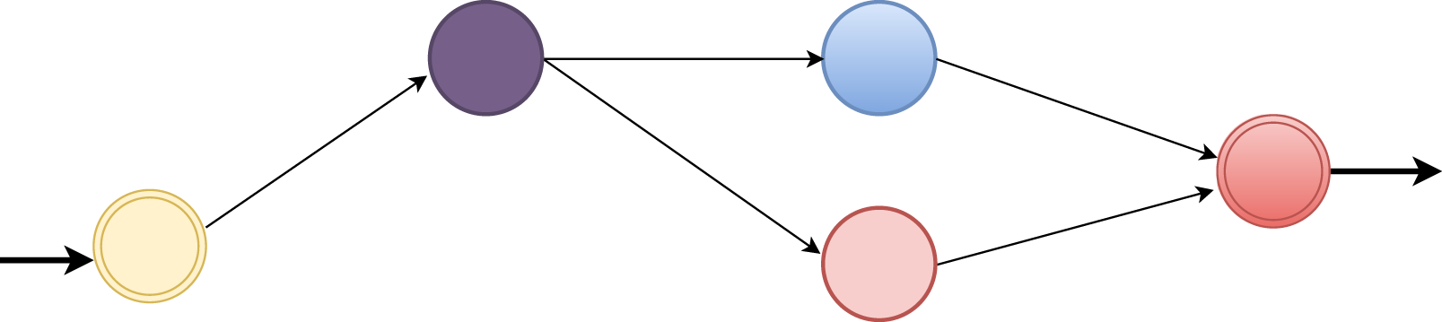
Sensor data generated from the edge requires analytics to extract useful information. RIoTBench (Shukla et al., 2017) is a real-time IoT benchmark that defines various data processing applications built from smaller tasks to process the edge data. Example micro-tasks in RIoTBench implement functions such as filtering, parsing, averaging, counting, training machine-learning models and making predictions on incoming sensor data. We focus on implementing required data analytics compute kernels and building task graphs for IoT applications.
Figure 3 represents the internals of an InPE with three key elements: networking pipeline containing ingress and egress paths, RISC-V soft core for executing baremetal C code, and instruction and data caches storing instructions and data. An Instruction Set Architecture such as RISC-V has smaller fixed-width instructions, therefore, consumes minimal hardware resources to decode and execute instructions (Kanter, 2016), increasing the quantity of compute units. INDIANA with its processing element representation and pairings of multiple processing elements of different variations for data parallelism.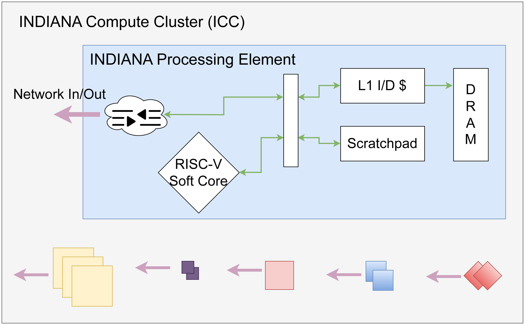
Data traversal within an InPE is similar to a core’s traditional data traversal path. Incoming data from a network switch arrives at NIC registers, which are then visible to the CPU through the memory-mapped address space or placed in the cache/DRAM hierarchy. We model data traversal across several InPEs using Flange for flow direction. Flange generates switch rules based on service identifiers corresponding to InPE-InPE movement, and each InPE outputs data stream packets intended for the subsequent service through a service identifier. In addition, we indicate that by logically grouping multiple InPEs via a shared memory region, we can support operators that benefit from data parallelism.
Serverless Architecture
Section 2.1 discusses the relationship between programmable network hardware, virtualization, and task graphs. In this section, we discuss how the complete INDIANA design offers a serverless architecture on top of the programmable network hardware.
In-network FaaS Architecture
Traditional virtualization methods for deploying applications, creating isolated environments for different applications, and providing adaptive scheduling for dynamic incoming streams depend on two main approaches. Either the applications run on Virtual Machines (VMs) or containers. VMs have isolated guest operating systems, each of which runs on host operating systems. A hypervisor is responsible for creating the virtualization infrastructure associated with VMs. Containers are a lightweight alternative for deploying applications compared to VMs, which utilize host operating system services to create the virtualization infrastructure. These virtualization methods also provide ease of application development to the developer, as any application can run on top of the VMs and containers (Jha et al., 2021). Inherent to these virtualization methodologies lies largely unavoidable overheads associated with providing virtualization and processing network packets on a software network stack. Specifically, spawning new VMs or containers requires a heavy setup phase. In contrast, there is faster hardware that can process incoming network packets at nanosecond speeds and requires a light setup phase. Recent research named In-network computing focuses on utilizing programmable network hardware to also support computations for network-heavy applications (Tokusashi et al., 2019). However, programming these hardware devices is not immediately apparent.
Figure 4 shows how our idea for in-network based virtualization looks compared to VM and container-based virtualizations. For a serverless architecture, InOps are equivalent to serverless functions connected internally via service identifiers. We model services in INDIANA as functions with a single objective, and with new RISC-V instructions backed by faster hardware accelerators to achieve high performance. In contrast to hypervisors and container engines, our proposed system has lower latency for NIC-CPU data traversal due to the absence of a software network stack. Stream processing in high data-rate environments benefits from long-running services, but can be short-term based on resource availability in our system. In-network FaaS platform architecture.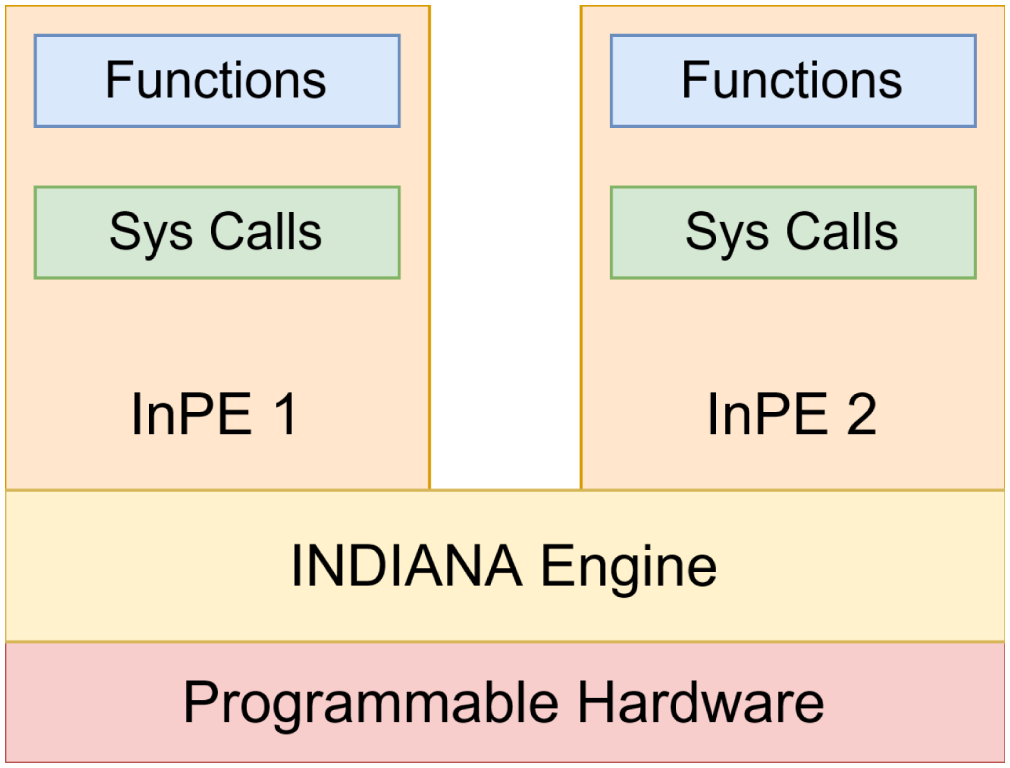
In the previous section, we discussed the internals of an InPE, and here we represent the logical idea of each InPE supporting MMIO-based sys calls and functions. The component in an in-network Function as a Service (FaaS) architecture that supports virtualization is the INDIANA Engine, which acts as the tool that connects both the low-level programmable hardware and high-level functions, which we discuss in the next section.
INDIANA engine
Serverless functions have unique characteristics such as dynamic scaling, easy deployment, and reduced latency. To support these characteristics on programmable network hardware, such as FPGA or ASIC-based Smart NICs, we introduce the INDIANA Engine, as shown in Figure 5. We have several components, such as Thread Scheduler, Stream Scheduler, and Service Registry, on top of which we provide adaptation and virtualization. As stated in the earlier design sections, we heavily depend on the Service Registry to connect the programmable compute cluster and SDN-capable switch (§3.5). Flange schedules incoming streams and forwards them to the correct core acting as the Stream Scheduler in both Execute and Adaptation stages. Flange also provides updated function placement during the Adaptation stage, given a use case where a core cannot manage an incoming data stream. Meanwhile, the Thread Scheduler decides which threads run on a core. However, for our initial implementation, we assume a 1-1 relationship between cores and threads. INDIANA engine.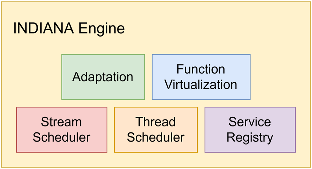
In the sub-sections below, we describe important concepts related to Flange.
Generalized Flow Placement
Having established a mechanism for injecting InOps onto an INDIANA compute node, we now have the groundwork laid for a more generalized interface for operating on network flows. For the purpose of this examination, a network flow is any set F of packets with consistent identifying features that distinguish it from packets not in F.
This is a much broader definition of a network flow than you will see in much of the network orchestration literature. In brief, by broadening the definition of a flow, we allow our analysis of network behavior to be sufficiently flexible to support unconventional network topologies. We will address the larger ramifications and justifications for this definition in more detail in Section 3.
Our goal with INDIANA is to provide a general purpose solution for operation placement within an arbitrary network topology. Generalized operation placement requires three discrete components: programmable hardware, a best-effort algorithm to solve for resource allocations, and a mechanism for defining and controlling the placement algorithm to suite the demands of a given problem domain. The first we have already discussed in Section 2; a method for installing arbitrary InOps onto a variety of network hardware. Each of these compute nodes is capable of further specialization into InPE slices so as to improve flow level parallelism. Expanding the scope outward, even a perfectly optimal placement within a single computation node is still non-optimal if there exist nodes with higher spacial affinity to the packets in the network flows being serviced.
We take a network wide approach to placement by treating all compute nodes as a single pool of resources which are labeled by their affinity to each flow. This allows us to solve the intra-node and inter-node placement of functions in the same pass.
Consider a virtual compute node representing the totality of the available compute resource on the network sliced into N InPEs with a capacity

We further specify the set of flows F as

There is a cost function ψ ( f ) for the unit cost of placing an operation onto an InPE. We would like to identify a mapping

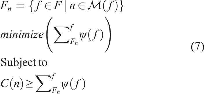
This formulation shares similarities to both the bin packing and number partitioning problems (Martello and Toth, 1990). However, it differs in a few key ways. Our goal is to maximize the available parallelism in the system; conventional bin packing approaches will minimize the number of bins while maximizing the allocation per bin.
Multiway number partitioning shares more in common with the above, but differs again in one key way: our use of elastic bin sizes allows us to upgrade a bin to a larger size for greater capacity at the expense of parallel execution.
We developed an algorithm that instead maximizes the number of bins within a constrained space, collapsing bins into larger bins on an as needed basis.
The constraints in Equation (7) are also insufficient to describe a real world multi-commodity function placement problem. For this, we need to further specify the function color of a flow. Since flows may have multiple functions applied in sequence, we define color as a mapping


Considered as a whole, Equations 7 and 9 define the algorithm we use to perform function placement in INDIANA.
Each flow is labeled by a set of desired operations and each node is labeled based on its candidacy for acting as a solution for each flow. A solution is generated all at once for all flows by aggregating all compute nodes into a single virtual node and solving for the minimal load per InPE.
Defining discrete applications
Having defined our placement constraints, we need a mechanism for specifying the parameters of a discrete instance onto which our algorithm should be applied. For this purpose, we have implemented the Flange NOS.
The Flange NOS is broadly composed of three components: A frontend compiler that consumes human-writable high level, flow-oriented declarations and produces Flange Assertion Graphs, a backend resolver that takes serialized Flange Assertion Graphs and apply them to a specific network topology, and a runtime service for re-validating existing programs as needed as the network topology changes. The relationship between these three components and the underlying network topology is shown in Figure 6. Depicts the flow of information within the Flange NOS.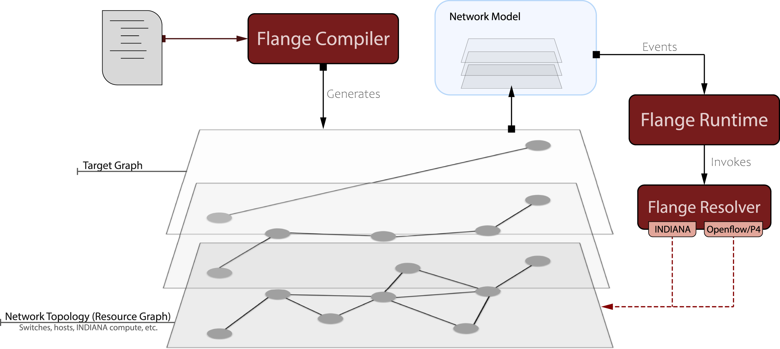
Implementation
INDIANA processsing element
We envision the use of programmable network devices in order to realize a fully integrated network architecture for deploying low-latency microservices. Different programmable networking devices are built using a variety of types of hardware including Application Specific Integrated Circuits (ASIC)s, Network Processors, and Field Programmable Gate Arrays (FPGA)s. ASICs provide fast packet processing but have fixed functionality and can be hard to program. Network Processors are more flexible and may be easier to program, however, the high throughputs required for network-heavy applications require heavily optimized application designs. FPGAs provide a middle ground, outperforming Network Processors without sacrificing too much programmability. In this work, we realize our design using RISC-V soft cores (dynamically instantiated, general-purpose RISC-V processors) on FPGA-based Smart NICs in order to achieve flexibility, performance, and determinism when executing applications.
This work builds on top of prior work discussed below, specifically for the INDIANA in-network processing elements, or InPEs. The initial version of an InPE was found in InLocus (Brasilino et al., 2018), where we presented an in-situ stream-oriented architecture designed around Vivado’s High Level Synthesis capabilities (HLS) in which C-like code is compiled directly to low-level, FPGA register-transfer logic (Xilinx, 2021). HLS hardware modules provide orders of magnitude gains in performance over NodeJS or linux-based C reference solutions, while at the same time benefiting programmability as application developers implement high level code to interact with hardware components written in Verilog. However, HLS limits our ability to implement a dynamic and adaptive function deployment architecture because the FPGA must be dynamically reconfigured, which requires extensive hardware knowledge and is time-consuming.
The second generation InPE was developed as part of NetFaaS, where we investigated how we can achieve performance similar to Verilog hardware modules but with more flexibility and programmability (Ossen et al., 2022). NetFaaS introduced RISC-V soft-core based stream processing services relating to our work, used an Ethernet MAC Address-based service identification scheme, and introduced a new dual-ported memory implemented in hardware. The memory used full and empty signals (identified based on data availability) to control the handshake between the core and memory, reducing memory access latency. HLS module hardware resource consumption increases with increased functional complexity, while RISC-V soft cores have fixed hardware complexity and are a suitable alternative that provides general-purpose computation with better utilization.
In this work, we extend the notion of an InPE to encapsulate any compute architecture that can be deployed into our network, with a focus on heterogeneity and dynamic adaptive customization. This third generation InPE model forms the basic unit of in-network computation and is the target on which InOps are bound (Section 3.2). While we use the term InPE to characterize a class of objects, our evaluation of the full-stack INDIANA framework requires concrete cores and performance metrics. Our evaluation in Section 4.1 will characterize the performance of the unmodified BOOM (Asanovic et al., 2015) RISC-V implementation deployed within the FireSim tiled network framework (Karandikar et al., 2018), which can be viewed as simulating a potential real-world heterogeneous network target.
INDIANA operator placement
Given a set of statically provisioned InPEs as described above, we need a mechanism for mapping INDIANA operators (InOp)s to InPEs. This mapping should be as close to the theoretical optimal mapping for flow allocation as possible to minimize packet loss due to congestion or node over-subscription.
We implement a greedy approach to this InOp placement problem, which shares much in common with the bin packing problem. Our solution roughly follows a Worst Fit approach to bin packing. While Worst Fit matches the approximate optimality guarantee of the more efficient Next Fit, our use case includes the additional constraint of minimizing the work per node. While this results in a larger overall time complexity by a factor of
A similar result can be achieved through Best Fit, however, the conditions of the underlying network are in flux-spikes of flow congestion must be accounted for. Best Fit provides similar time complexity and resilience to flow migration, compared to Worst Fit while maintaining a stronger approximate optimality guarantee but is brittle to intra-flow fluctuation.
Our algorithm begins by modeling each node as a set of unlabeled tiles categorized into cost tiers read from the Service Registry (Figure 1). Tiles ultimately map to discrete InPEs, but we will use an abstraction here to distinguish the internally mutable tiles from the discrete deployed InPEs. Each tile is annotated with a capacity, cap, and cost, ψ. The cap of a tile is considered to be the maximum capacity of a tile of size C minus the resident set of flows
The basis of our algorithm is the iterative tile collapse procedure; any set of tiles S may be replaced by another tile d provided ψ(S) ≥ Ψ(d) and cap(S) < cap(d). This provides us with a framework for elevating tiles up the hierarchy if more capacity is needed. We will call this the
We maintain the upgrade cost of a tier, Ψ, distinct from the individual tile cost ψ because while these functions are the same in the common case, keeping them distinct allows clients to disable the upgrading behavior in the algorithm by marking the tier cost as ∞ if the hardware does not support flexible core sizes.
When there is no tile on a node that satisfies the cap requirement for a flow, we perform a
To solve the multi-flow version of the problem, we extend our definition to create two tensors: the NxF node tensor
Network flow scheduler
At its core, the Flange NOS acts as a flow-oriented graph solver. By taking in the current state of a network as a graph and comparing it to a desired state in the form of a Flange Assertion Graph we can generate a list of differences. The myriad of components and functions in Flange that we describe in the following section all act in service of this core tenet.
The Flange resolver is responsible for the process of resolving the Flange Assertion Graph into a discrete set of topology changes. The assertion graph is a list of proposed flows, each of which contains a list of facts associated with a candidate flow. We address the particulars of the assertion graph representation in detail when we examine the Flange compiler. The first phase of the resolution process is to take the assertion graph and identifying all possible flows described by the graph. This first phase is called the Flow-Expand pass. It only performs expansion on each candidate flow into a discrete, realized flow based on the current state of the topology at runtime.
To explore the practical intent behind the Flow-Expand pass, consider Program 1 in the Flange DSL (Section 3.7).
Listing 1: sample program
This program is semantically congruent to a gather operation from all nodes of type “foo” to a single other node. At compile time this program does not define a number of flows to be generated nor the identity of the node
When resolving flows, changes are described as either interfering or non-interfering changes. For instance, terminating a flow at a node is a non-interfering change. In theory, terminating many flows at a single endpoint may have knock-on effects. However, for all practical purposes, we assume terminating a flow does not affect other flows in the network. In contrast, mapping a function onto an InPE node is an interfering change; for a node of any capacity, there is a certain number of processed flows, at which point the node’s performance begins to degrade, and packets drop.
For this reason, we cannot solve flows independently. The placement of function λ n may preclude the placement of λ m . Instead all flows undergo a sequence of transforms in tandem, starting with the Flow-Path resolution pass described above.
We consider the result of the Flow-Path pass to be a set of candidate flows
This set of iterative candidate solutions lends itself naturally to a modular approach to the Flange NOS. The backend is made up of a series of modifier passes. Each modifier is made up of a validator and a resolver. A modifier’s validator is run on candidate paths before resolution is attempted. In doing so, we can preemptively reject paths that are trivially identified as non-satisfying. For instance, if a flow expression included a fact asserting the existence of a function λ, any path matching the top level conditions of the flow that does not contain a programmable InPE node can be rejected before any costly placement calculations are performed. A modifier’s resolver consumes a validated path and performs a difference operation between the current state of the candidate path and the collection of facts. Each modifier defines for itself how to resolve any given fact. Continuing the example above, the InPE resolver would identify an InPE node along the candidate path to place the λ function (Section 3.2). If no such function already exists, the pass emits a delta including the following flange assembly instruction:
In contrast, the Routing modifier identifies and injects forwarding instructions into the delta based on the type of each node in the path. During this pass, each forwarding instruction is considered independently and is assumed to be a full-field match.
The aggregation of such instructions across modifiers represents an unordered change list generated by the Flange NOS. Network agents such as the INDIANA Service Registry and SDN controllers consume these changes and modify their internal state as requested to reflect the included instructions.
This naive approach is sufficient for many use cases. However, while the resulting solutions will satisfy the prepositions asserted on the network, it is clear that certain flange assembly instructions will result in poor performance if left in an unordered, non-processed state. Up to this stage, flows are processed simultaneously in order to allow modifiers to identify invalid solutions due to inter-flow interference. The resulting instructions are still generated on a flow by flow basis. As a final pass, we perform the trivial transform on the result from a flow-oriented domain to a node-oriented domain. Then each node’s instructions are aggregated by category and forwarding rules are consolidated into a longest prefix match form where applicable.
Thus far we have described the behavior of the Flange NOS as an independent service. Now we will examine the practicalities of the NOS dependencies, the Flange Assertion Graph and the UNIS network model (El-Hassany et al., 2013) which together form the inputs for the Flange NOS as seen in Figure 7. Flange identifies optimal function placement for the network topology (light blue) then inserts forwarding rules to create the circuit as needed (maroon) in Figure 6. Changes to the network are fed back into the model.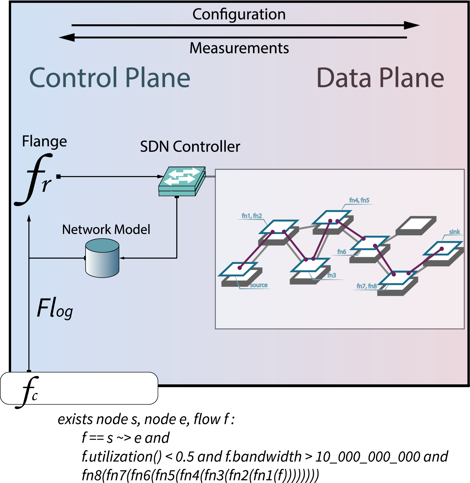
Flange assertion graph
The Flange Assertion Graph (FlAG) is an entity fact tree. A Flange entity E may be any virtual node or flow. Each entity of discourse is included in the FlAG along with a list of predicates or facts which must validate successfully in a candidate solution for the entity to be considered a satisfying solution. Furthermore, in a General FlAG each entity may contain any number of dependent FlAGs. Entities with children at layer n are only satisfied if at least one child at layer n + 1 is satisfied. Let’s consider the Flange program
Listing 2: INDIANA sample program
Program 2 is an archetypal, if simple, INDIANA program written in the Flange DSL (Section 3.7). It describes a scenario wherein a network contains a set of nodes such that at least one node is of the The Flange Assertion Graph for the sample INDIANA program.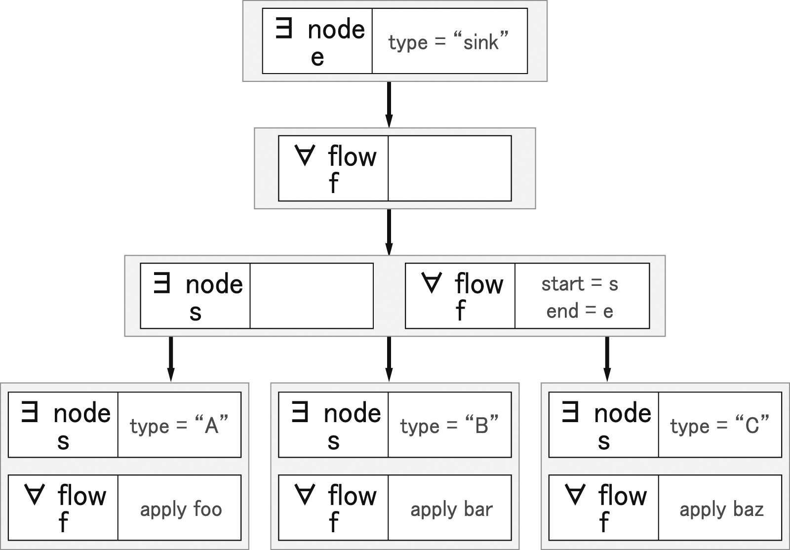
As a first-order logical language, in practice the general Flange Assertion Graph is a predicate logic tree. As a consequence, we can apply any logical permutations on the tree that is permissible within a first-order logical system. While there are certain advantages to this tree-like formulation of a flange program, it does not lend itself well to the flow-oriented approach of the NOS backend. We need to convert the FlAG into a flat, flow-oriented decision space. Fortunately, this operation is well established: we simply remove the existential quantifiers and replace them with functions that map to corresponding results and flatten the tree, this transforms the tree into a Skolemized disjunctive normal form as seen in Figure 9. Each disjunctive stanza can now be treated as an independent network assertion by the Flange NOS. The Flange Assertion Graph for the sample INDIANA program converted to DNF form.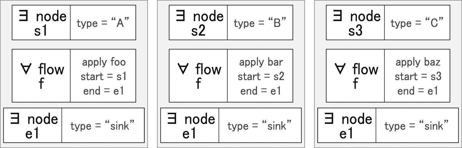
Flange network model
We use an active network model stored in a NoSQL database using the Unified Network Information Service schema. This model may be populated through in-network probes, SDN controllers and manual administrator configuration. The UNIS schema defines
For use in the Flange NOS, we need to be able to model complex network interactions for any useful application. UNIS facilitates multi-layer networks through virtual nodes and links layered hierarchically through ports. A node entity may represent a host, switch, or network depending on associated ports. Node capacities and capabilities are included as entity annotations. The Service Registry described in Section 2 is also implemented as annotations in the network model. This keeps the network model as the ground truth record of network state and allows us to map Flange assertions to model fields through a form of duck typing. Any nodal assertion in a Flange program is considered to be valid if and only if the associated annotation exists on the node in the model and the value of the annotation satisfies the comparison operation.
The dual of the node/network relationship is the link/flow relationship, which behaves in the same way. UNIS link entities may either represent a link or a flow. Links are distinguished from flows by their mutability. Links represent existing features of the network. They may have annotations, but these annotations are only used as the basis for invalidating assertions. In contrast, flows are considered mutable and are identified by the layer of their endpoint ports. Conceptually, the network graph can be viewed as a hypergraph with flows as directed hyperedges. In our experiments, however, we do not expand our model to support this feature; point-to-point flows are sufficient to model our testing scenarios.
We refer to this model as the active network model because it can be augmented with live measurements. Any edge E contains an arbitrary set of measurements. These measurements are identified by a metadata record that uniquely defines an event type and subject entity.
These measurements are used by the Flange NOS in both implicit and explicit ways. Implicitly, any backend modifier may reference a measurement in order to validate or resolve candidate paths. Of particular note to INDIANA is the InPE modifier, which uses measurements on existing flows to better schedule function placement. In the placement algorithm described in Section 3.2, we refer to a cost function
The specifics of how per-flow packet-per-second measurements are generated will depend on the deployment environment but could easily be generated in flight by SDN meters or defined at the source as part of the data generation. Flange itself is agnostic toward the source of the measurement data and assumes the model is a best-effort reflection of the current state of the network. In the absence of a packet-per-second measurement, the behavior is modifier dependent. In the case of InPE, it will fall back to the average rate of existing flows and failing that, use a default estimate defined at compile time.
Alternatively, measurements can be invoked explicitly in a Flange program by calling the measurement as a function on a flow within the program. In Program 3, a single flow between nodes
Listing 3: INDIANA sample program with measurements
During compilation, measurement requests yield a deferred event record. At run time, this event record yields the current state of the measurement. The collection of all event records generated for a given program is considered the program’s event domain.
Passive versus active flow scheduling
The Flange NOS can generate the solution for a program on demand which is then passed to in-network agents that work as actuators on the network, reporting the new state back to the network model. This is the passive execution model of Flange as described thus far. Changes to the network are only applied at the request of the administrator on the execution of a new policy.
This mode of scheduling is insufficient to perform as a production NOS. Conditions in the network change. At the macro level, new data sources may be added, extra links may be connected, and new Programmable Node modules may be installed. At the micro level, data source flow rate may fluctuate or other services may contest the resources used by a program.
In order to address the inherent mutability of the network, we introduce a manager service called the Flange daemon. The Flange daemon primarily acts as a network program scheduler. When compiled, a FlAG is registered with the daemon; newly registered FlAGs are immediately flagged as invalidated. In conventional OS terms, this queues the process as pending.
The Flange daemon runs pending programs against the network state as it appears at execution time. This execution generates two products as described in Section 3.3: a delta list and an event domain. The delta list is immediately deployed to the network where rules are inserted as needed. The event domain is fed back into the Flange daemon as a collection of potentially invalidating conditions. Each condition is registered to the FlAG that generated them.
When a change in the network model is detected, the new state is compared to the event domain of each registered FlAG. If an event fails a validate, the FlAG is marked as invalid and placed in the queue for re-evaluation.
By using this approach, we have traded optimality for performance. Only invalidating changes in the network prompt a re-evaluation of a program. As such, some changes that may result in a more optimal solution will be ignored, since they do not invalidate the current running solution.
In practice, this is preferable, since re-configuring the network involves a substantial cost in terms of network disruption and flow instability until the new solution is fully installed. We can mitigate potential network disruption by using transaction-based transitions, but this incurs a further performance penalty during rule placement. Instead, we minimize network disruption by only modifying the current network state when a program is invalidated. Furthermore, potentially costly re-evaluation is only executed in the case where a member of the event domain is changed.
We can optimize our active resolutions further by tagging event domains with specific DNF stanzas/flow pairs within the FlAG. Since stanzas only interfere if they contain overlapping paths, an event that invalidates a subset of the FlAG only requires a re-evaluation of the invalidated stanzas. This partial re-evaluation is limited to solutions that do not invalidate non-triggered stanzas. In the case of a partial re-evaluation failure, the entire FlAG will be triggered as pending.
This process allows the Flange daemon to maintain the state defined in a set of programs in the face of network topology changes and performance fluctuations.
Flow policy language
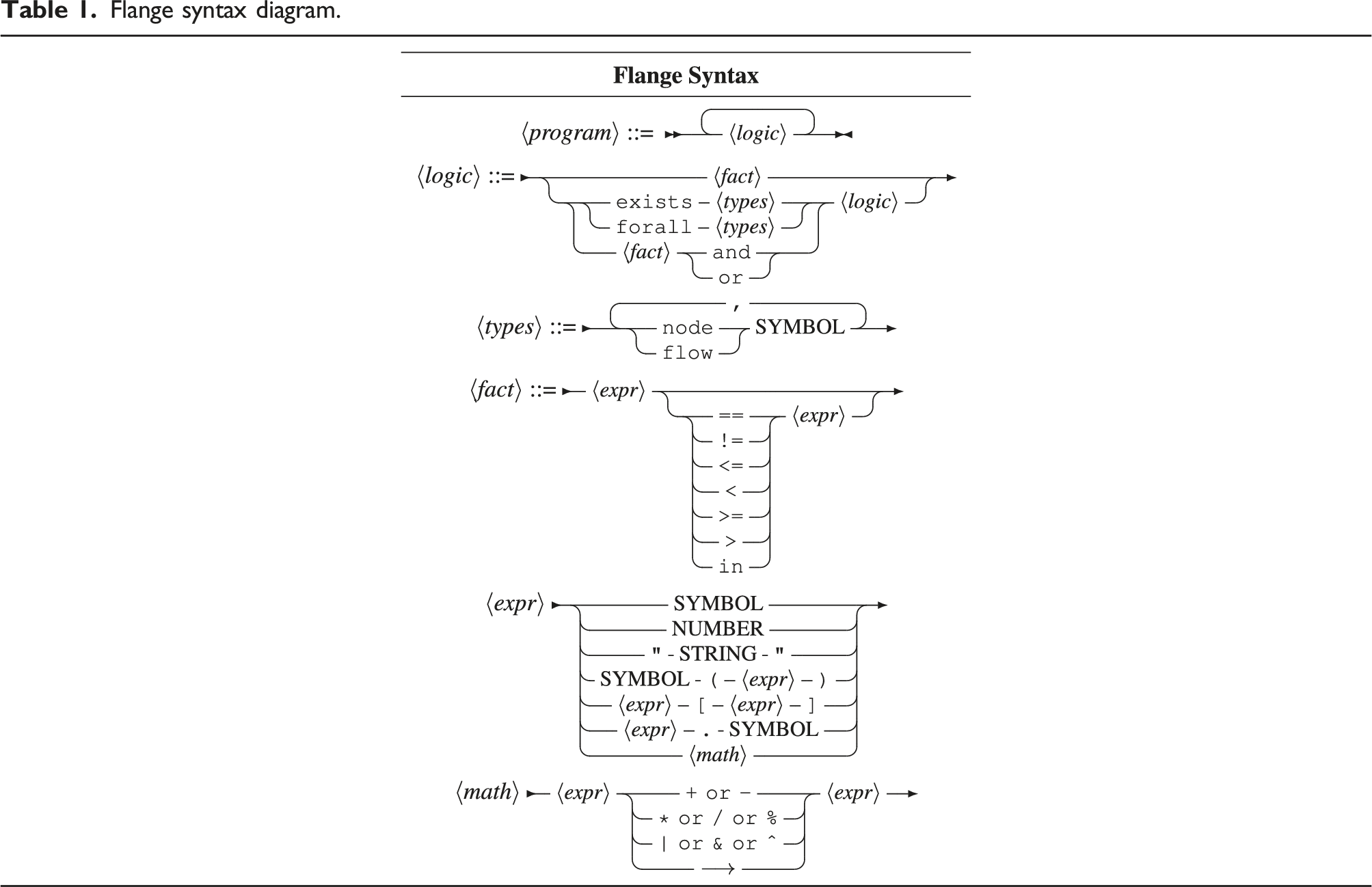
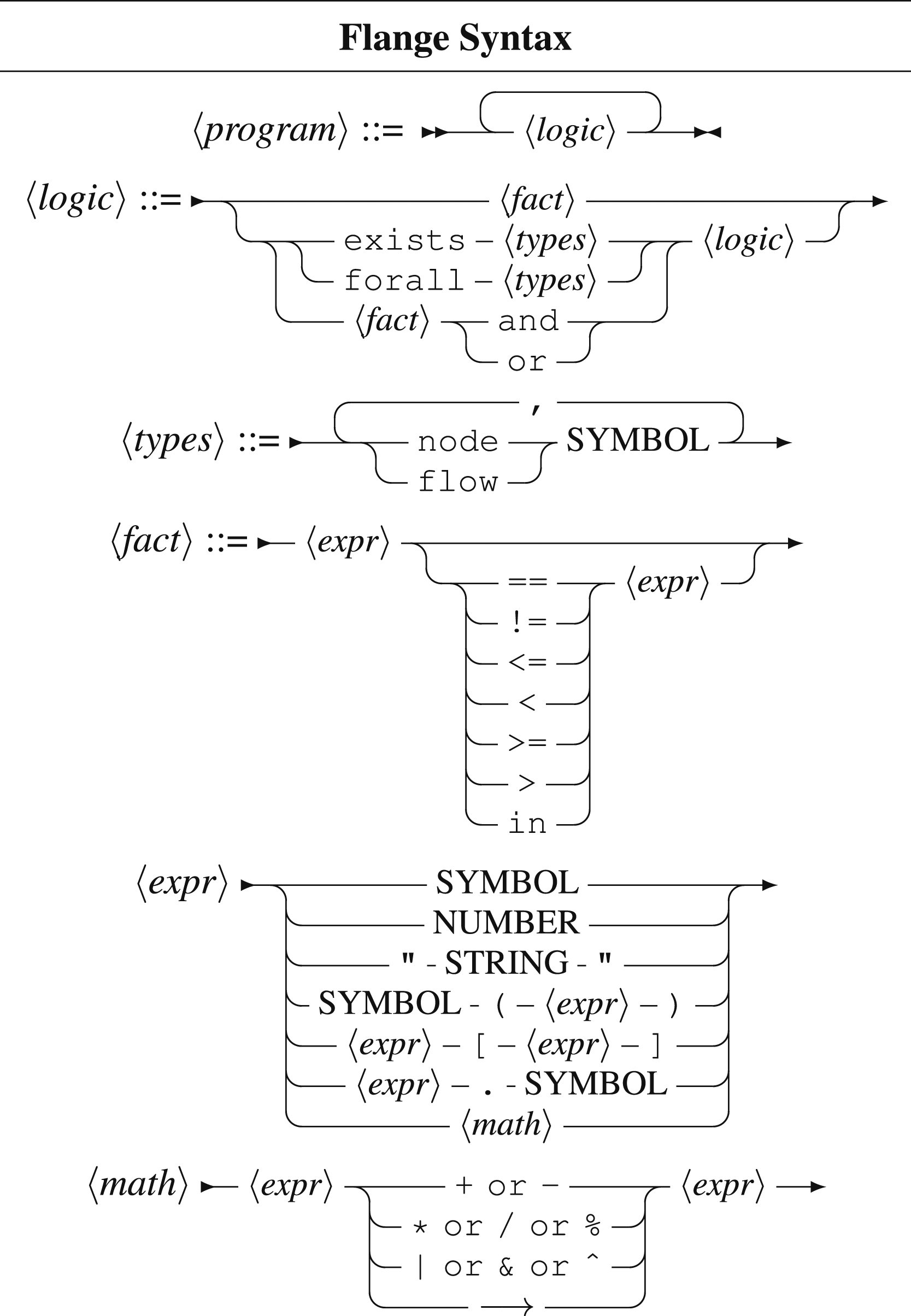
The Flange language was designed to codify network flows into a concise, declarative form. Conceptual network models exist in a spectrum of abstractness from physical to logical. A fully physical network model has the advantage of completely defining the behavior of the modeled network, but suffers from its own complexity. Inferring meaningful information from a physical network model is difficult. The behavior of a given node or link in the model is defined by the hardware specification, adjacent entities, levels of encapsulation, etc. Writing a policy to modify the model state is still more complicated. The user needs a full understanding—not only of the individual systems in the network—but the interactions between systems. For this reason, Flange attempts to divest the developer entirely of the physical topology, allowing them to express their intent purely in terms of the logical flow of content. Flange programs take the form of first-order logical expressions over the domain of logical nodes and flows.
Modern SDN projects such as Firmament (Gog et al., 2016; Merlin Soulé et al., 2014) inspired many of the features in Flange and our approach of modeling networks at a higher, more abstract level. It could be said that SDN itself is a continual effort to lift the domain of discourse from physical to logical abstractions. However, existing approaches use node or packet level abstractions when defining behavior. In contrast, Flange is a flow-oriented language. In Flange, non-flow types, such as nodes, exist only to express specificity when validating flows. Flange combines this high-level abstraction with explorations into declarative network specifications such as (Anderson et al., 2014; Chen et al., 2010; Foster et al., 2011; Hinrichs et al., 2009; Monsanto et al., 2012). Programmers express the behavior of flows by defining the matching parameters that shape the flow. For example, in Program 3, we define a flow
Flange syntax diagram.
This formulation of a path is quite powerful; for many applications, simply being able to express point-to-point paths is enough to achieve useful and robust behaviors. In the INDIANA context, we wish to take this approach a step further. As a functional concatenation operator, the flow operator can be chained, Flange will optimize for the outer pair on paths that pass through all vertices requested. This looks like sum(A → B). The expression can be read as the flow from A to B passing through the function sum. This example assumes a stream of numeric data is being generated by A. Function predicates can be chained indefinitely as needed.
Flange uses link virtualization to treat flow predicates as a single edge between two vertices. When the flow is fully resolved, each hop within the virtual edge is annotated with the necessary forwarding changes to realize the described virtual edge. By reducing all flows to a single edge, all flow problems can be generalized into a single overlay topology before finally resolving down the physical topology in the resolver.
Quantifying assertions
In order to fully specify the relationship between network entities we use the forall and exists quantifiers. When viewed as a formal first order logical language, Flange inherits the predicate logic solution here; node and flow types are bound using the existential and universal quantifier. Validating facts are processed over the variables thus quantified. Recall that facts map to predicate expressions in the FlAG consumed by the Flange NOS. There is a more practical application for quantifiers in Flange; however, it is necessary to have a mechanism for distinguishing how a flow should choose constituent elements. Quantifiers help us to distinguish between a generative operation and a filtering operation. The universal quantifier queries a collection of entities that currently satisfies the descendant facts referencing the quantified variable.
In contrast, the existential quantifier can be generative; if a satisfying entity already exists, the NOS will attempt to satisfy the FlAG by iterating over the list of entities that match to predicates for the variable with short circuiting-search will terminate prematurely on a solution. Unlike the universal quantifier, if no satisfying solution is found with the existing entities, Flange will attempt to generate a satisfying entity.
When the Flange NOS receives a request for an existential flow and no existing flow satisfies the descendant predicates, it instead generates a flow de-novo provided some entity exists that satisfies the start and end points for the proposed flow. The flow generation happens as part of the Flow-Path resolution pass provided at least one physical path exists onto which the flow can be injected. Subsequent passes do not need to consider if the flow under consideration has been generated or is an existing flow to be modified. As such, the modifiers can treat all flows as existing flows to be modified, greatly simplifying the system logic.
In the case of an existential node, our current implementation terminates and informs the user that the program is unsatisfiable. Nodal generation is theoretically possible, provided an agent like KVM, Puppet (Benson et al., 2019), or Ansible (Ansible, 2017) capable of generating system configuration for hardware or VMs. This is beyond the scope of this examination of the INDIANA architecture, however.
Recall that we use a disjunctive normal form for expressions fed into the Flange NOS. Disjunctive normal form does not include quantifiers, so we perform Skolemization on the FlAG. This process converts all references to variables to either discrete instances or closures that take the current scope as arguments depending on the type of quantifier used to generate the variable. Universal entities are converted to discrete variables while existential entities are converted into Skolem functions.
Beyond conforming to the formalities of first-order logic, Skolemizing the FlAG provides us with a practical abstraction when interpreting the expression in the NOS. Each reified candidate flow contains a symbol table with associated universal variables. This maps well to our model where each flow is considered a distinct unit satisfied concurrently. Skolem functions are implemented as a generator with memoization across the entire environment. Each Skolem function returns the same result for each closure environment while allowing the Flange NOS to iterate across candidate matching entities.
By compiling the Flange program from a human-writable format to a Skolemized disjunctive normal form, we can interpret the resulting sequence of clauses as discrete flow requests. Each flow request can then be passed through a sequence of modifiers applied to a network instance to generate a final proposed set of instructions to actuate on the provided network.
Evaluation
In this paper, we perform two sets of experiments. The first is to build a profile for RISC-V cores against various message rates. Different core settings and function complexities affect the time an InPE takes to process data and how well each InPE can handle the load. Next, Flange executes experiments constructing network switch rules and monitoring the network for data streams. Once an InPE reaches a threshold (computed using the RISC-V core profile), Flange generates new switch rules to redirect flows to larger more capable InPEs. We assume a static set of cores and build the profile offline for this work.
FireSim evaluations
The following FireSim simulation experiments are run on Amazon Web Services (AWS) F1 FPGA instances (Xilinx Alveo Smart NICs) (Xilinx, 2022) and are designed to collect meaningful real-world parameters to be used in the cost model for our modeling infrastructure, as evaluated below.
Function kernel description.
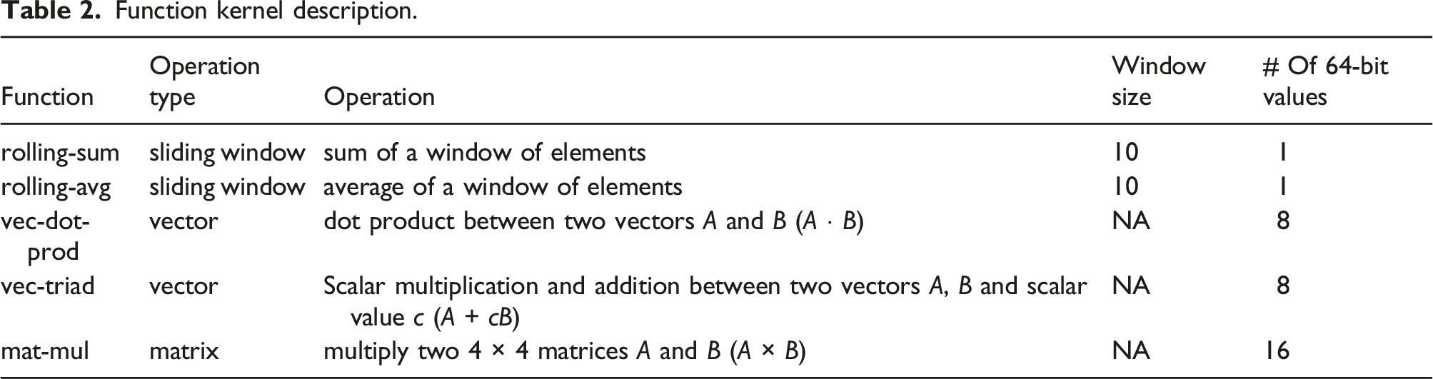
Figure 10 shows the timing information for the producer running on BOOM. We define the transmission time as the total time taken to send the data packets from producer to consumer, and it depends on the data payload size. As the message rate increases, for the same rate (same number of messages sent to the consumer), the difference between sending different-sized packets (1, 8, and 16 64-bit values) increases. As the NIC egress flow contains memory reads and transferring data via the network, each memory word read adds to the total transmission time. In this experiment, the maximum attainable message rate for the 1 Gbps NIC bandwidth is 6,000,000 packets per second without any loss of packets. We can increase the maximum supported NIC bandwidth to support transmitting more 64-bit data words and message rates on the producer without overwhelming the system. Timing information for BOOM Producer.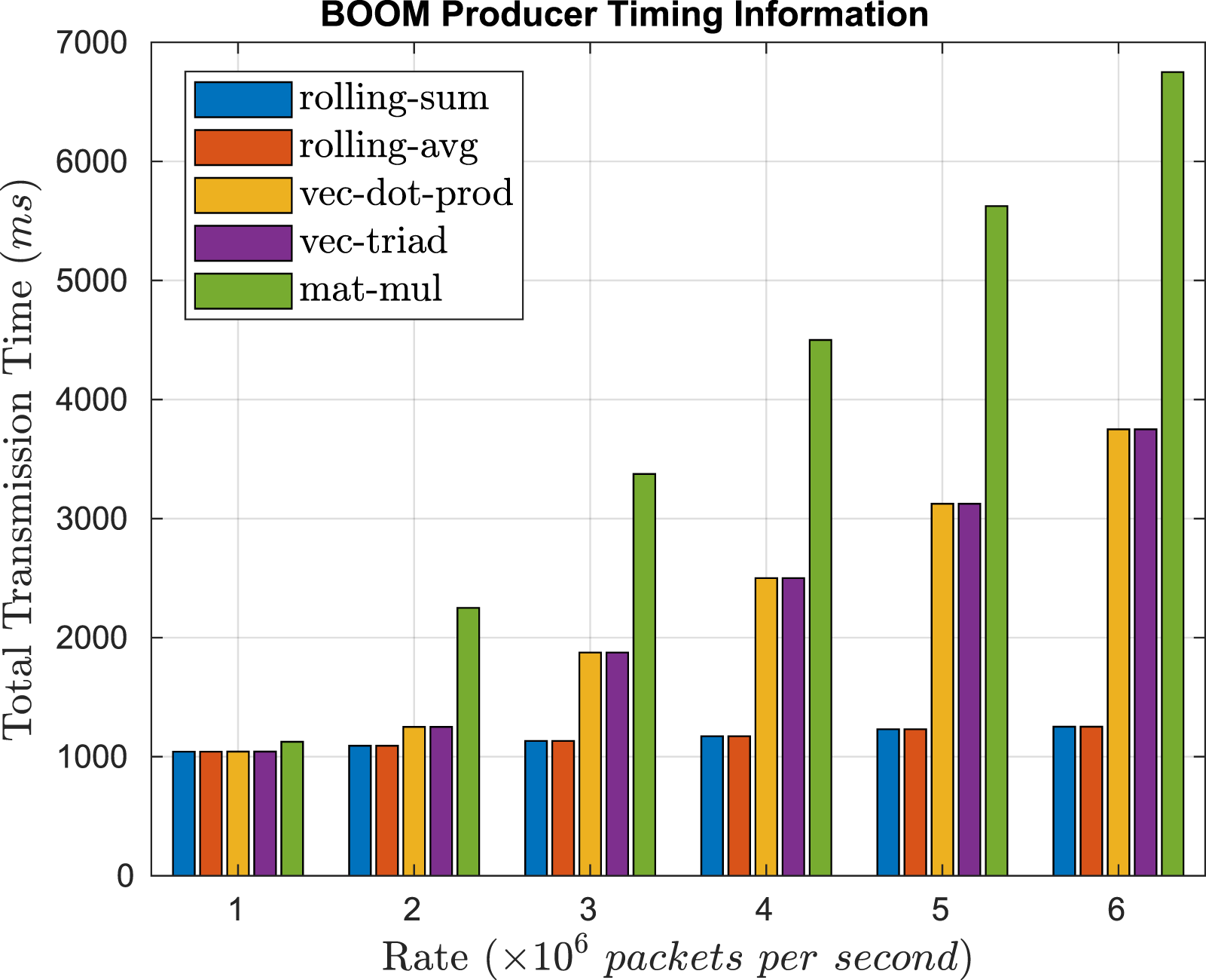
Figure 11 shows the timing information for the consumer running on BOOM. Here, we depict the total execution time, comprising the time taken to receive packets and execute the function kernels on the incoming data. Here, a similar execution time is seen for function kernel pairs (rolling sum and avg, sliding window and vector operations) as an equal number of operations is performed on an equal number of incoming data elements. As the function complexity increases, from simple addition, addition and multiplication between two vectors, and matrix multiplication, the execution time also increases. Timing information for BOOM Consumer.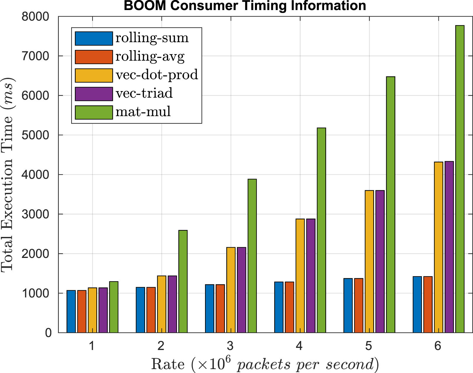
Function placement performance
In order to evaluate the performance of the Flange NOS, we ran two scaling experiments. We performed these experiments using simulated networks in order to examine a wide range of network scales and degrees of function density. Fortunately, the structure of the Flange ecosystem supports network simulation natively. By providing the model with a simulated topology and discarding the instructions generated by the Flange NOS we can perform placement operations on any arbitrary topology. Doing so fails to correctly simulate the feedback loop used by the Flange daemon in order to provide active network management, but since these experiments are meant to demonstrate placement performance, a simple passive application is sufficient. We considered the following three parameters during simulation: the density of data products, the producer count, and the InPE node capacity.
All placement scaling experiments were run on an Intel i7-8705G at 3.1 GHz and 16 GB of DDR4 2,400 MT/s. Each parameter sweep performs 100 runs per configuration; graphs display the mean performance and one standard deviation per configuration.
In our first scaling experiment, we maintained a simple policy across all runs with three product types and infinite InPE node capacity. Our goal here was to determine the effect of increasing graph size on the placement algorithm on a successful solution; limiting the InPE capacity would have injected failure states that would have increased the error for larger graphs without providing any useful feedback. The Flange NOS is able to perform early detection on flows that exceed the network capacity. This produces an apparent sudden performance improvement when the produced data exceeds network capacity—a useful feature for practical applications, but not ideal for examining the scaling behavior of our implementation.
Figure 12 shows our simple three product policy applied to networks with scaling source node counts. For this experiment, the graph is a simple star topology in which one virtualized InPE node and between 100 and 2,000 data producers are routed through a single programmable switch. Results represent the time required for the Flange NOS to calculate an InPE placement scheme and generate a routing plan for the n nodes through the switch (the cost of the latter is dominated by the former, but it is worth considering that these times also include the routing performance). Placement algorithm performance with scaling network size.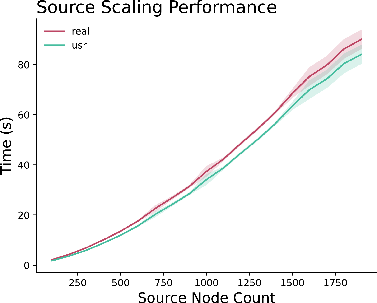
The choice to model this scenario with a single programmable switch lies in the virtualization techniques used by the Flange NOS. With no route optimization conditions in the program, a more complex routing topology—such as a Clos network—would be functionally reduced in model to a single routing vertex as part of the graph reduction pass. Making these two graphs isomorphic for all practical purposes in this scenario.
We observe a clear polynomial growth in placement performance. This is within our expectations based on our inheritance of the
It is our belief that with optimization of the constant factor, we will be able to further refine the placement algorithm to allow for fully responsive reconfiguration.
Interestingly, performance begins to become more unstable past the 1,500 node threshold in this experimental configuration. This is due to the implementation of the virtual InPE node’s properties. Past 1,500, the number of required collapse operations performed increases linearly due to the source cost exceeding the base number of available InPE tiles. Up to this threshold, collapse is performed only when necessary due to a particularly large flow exceeding the tile capacity.
Another observation here is the relative
Figure 13 shows the results of our second Flange scaling experiment in which we used a static 300 source network in a star topology with a single virtualized InPE node. The experiment scaled the function type density from 0.05 (15 function types) to 1.0 (300 function types) over the 300 source nodes in increments of 0.05. Placement algorithm performance as function type density increases.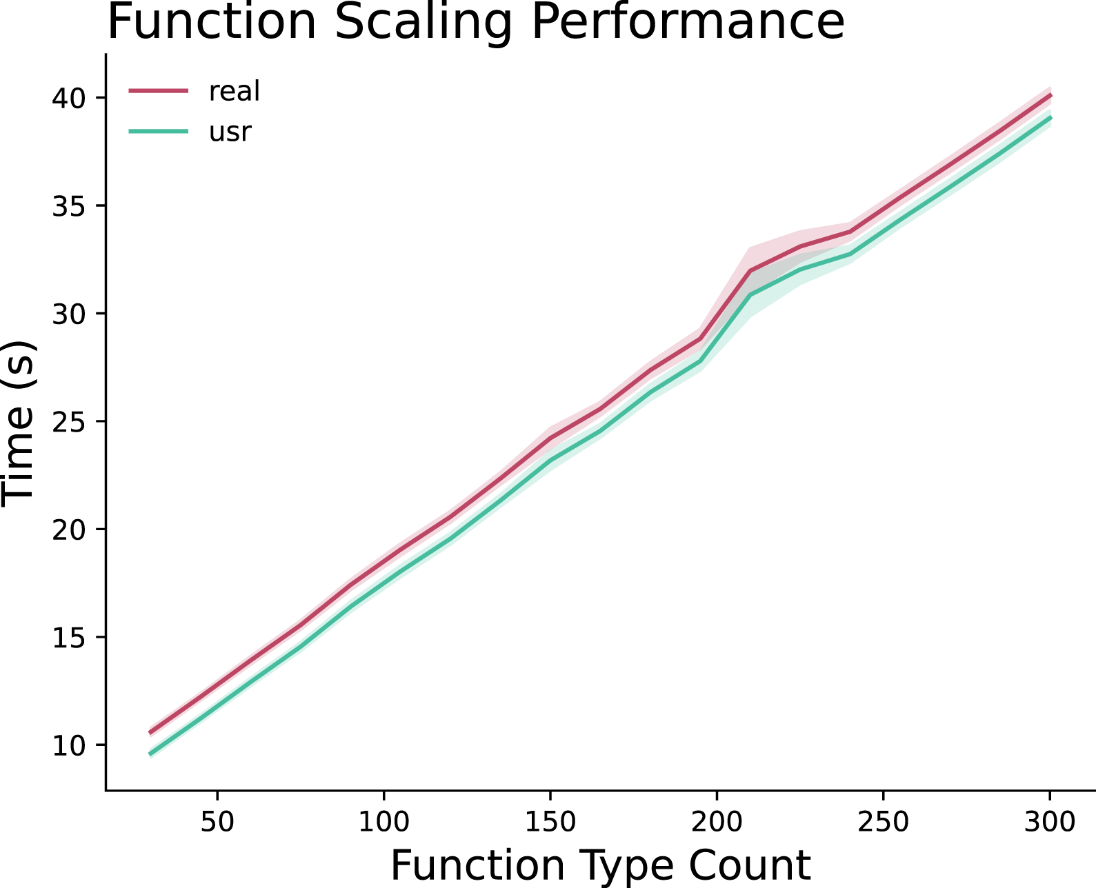
The performance scales linearly as function types are added to the solution. This scaling factor is the result of the Flange NOS’s attempt to find an optimal arrangement of functions on the compute node to balance the flows across the available resources.
There is a disruption around 225 function types. This correlates with the point at which the node can no longer place node function in place onto the node and needs to begin performing collapse operations to successfully place all of the function types.
Combining these two results, we confirm the average runtime of our implementation of
Limitations and future work
Low-level framework limitations
Implementing a low-level framework, designed to be immediately placed in or beside high-speed switching hardware, has limitations in the computation it can offer. Specifically, any operation that requires storing state, such as an element of windows, adds more complexity as we need to allocate resources for storage, reducing available resources for computation. Often performing compute-intensive operations also requires complex solutions (Kohler et al., 2018; Xiong and Zilberman, 2019; Zheng and Zilberman, 2021). We are limited in the capability to use existing software libraries known for improving performance. We also run into the problem of a heavily pipelined solution dropping packets in a network-intensive application when memory-intensive and compute-intensive operations dictate performance timing. However, using FPGA hardware accelerated modules and ISA extensions to delegate specific functionality from the core can significantly provide performance improvements. We intend to explore this space of solutions for significant performance improvements in future work.
Swapping workloads and reprogamming cores
In this work, we program each RISC-V core with the C code before starting the simulation using FireSim. Therefore it is equivalent to statically assigning programs at initialization. However, to be a framework supporting dynamic service deployment, we need the capability to swap workloads and reprogram cores on-the-fly. As previously stated, using partial reconfiguration for FPGA designs consumes considerable time. A less complex and faster alternative to reprogramming a core might be to associate a separate fast network path in the SDN-capable switch, introduce tiny packets containing the program code and utilize this network path to program the core via a reset. To realize this implementation, we will have to expose the L1 instruction and data caches and any scratchpads holding function code. We can either replace existing function codes or place the new function code in a separate address space and perform context switching between the hardware threads using the Thread Scheduler. We will be exploring these avenues in our future work.
Flow scheduling pitfalls
In the current implementation of the Flange language and NOS, there are several features that fall short of the intended design. A major hurdle when designing policies in the current implementation of the Flange NOS is the restriction of one logical flow per conjunctive clause. Every flow is considered an independent flow; placement and routing is performed dependently in the sense that flow a may nearly exceed the capacity on a node, preventing flow b from being placed on the same node, but it is impossible to express that a is directly dependent on the existence of b. The Flange language supports these types of assertions as seen in Program 4 but the NOS will reject the program as invalid.
Listing 4: A simple program with dependent flows
The logic in this program is similar to Program 5; in both examples, two flows are asserted, but in Program 4 the flows are dependent while in Program 5 each flow can exist or fail to exist independently.
Listing 5: A simple program with dependent flows
Transforming the solution space from a list of candidate flows to a list of lists containing dependent flows is the obvious correction, but invokes a performance cost for resolving dependent flows. We plan to explore optimizations that reduce the overhead of solving dependent flows in future work.
Policy language limitations
The type space used in the Flange language is ultimately very limiting. We provide the four constant types-
Listing 6: An hypothetical example of variable substitution in Flange
Furthermore, functions like the above examples
Implementing wider support for in language type definition and variable support would greatly expand Flange’s expressive power and is a major task to support future research to solve more generalized flow scheduling problems.
Related work
In addition to previous work performed in this project for in-network function placement (Brasilino et al., 2018, 2020; Ossen et al., 2022) and network orchestration (Musser et al., 2019; 2020), we took inspiration from several similar approaches described herein.
We investigate the execution of stateful dataflow operators within the in-network computing space first. Due to limitations on switch-ASIC resources, several designs propose approximation (Jepsen et al., 2018), careful estimation (Gupta et al., 2018), or finite state machines (Kohler et al., 2018) for evaluating stateful operators. In addition, the absence of general-purpose computing elements such as loops, floating point, and arithmetic operators support also hinders the ability to use fast switching hardware.
We also explore the work of network processors and FPGA -based in-networking solutions. λ-NIC (Choi et al., 2020) is an in-network serverless framework implemented on Netronome Agilio SmartNICs by defining an abstract machine model to deploy lambdas. NanoPU (Ibanez et al., 2021) is a design for deploying short μs scale services. A fast network path between the RISC-V Rocket core and the programmable NIC enables direct placement of message payload on core registers and subsequently provides low latency service times.
Conclusion
In this paper, we presented INDIANA, a generalized approach to deploying microservices that provides a high degree of control to users without incurring the performance cost of virtualization or containerization. We discussed our two pronged approach with InPE programmable execution units applied to clusters of Programmable Nodes in a Compute Cluster and workload orchestration across these clusters through the use of task graphs which are shaped and reshaped by the Flange NOS. This NOS applies placement policy to an active model of the network and generates placement plans across Compute Clusters to satisfy the asserted policies defined by users. We demonstrated that this placement scales polynomially respective to the size of the network graph and function density. The measurements obtained from running RISC-V cores on FireSim show that as function complexity increases, the execution time increases and that as the number of data elements in packets transmitted between nodes increases, the realistic time taken to transmit the values also increases. We intend to introduce new RISC-V instructions and hardware accelerators to mitigate this increase in time for both function execution and data transmission.
Footnotes
Acknowledgements
This research is based upon work supported by the Office of the Director of National Intelligence (ODNI), Intelligence Advanced Research Projects Activity (IARPA), through the Advanced Graphical Intelligence Logical Computing Environment (AGILE) research program, under Army Research Office (ARO) contract number W911NF22C0084 and the NSF Grant number 2126266. The views and conclusions contained herein are those of the authors and should not be interpreted as necessarily representing the official policies or endorsements, either expressed or implied, of the ODNI, IARPA, ARO, NSF, or the U.S. Government.
Declaration of conflicting interests
The author(s) declared no potential conflicts of interest with respect to the research, authorship, and/or publication of this article.
Funding
The author(s) disclosed receipt of the following financial support for the research, authorship, and/or publication of this article: This research is based upon work supported by the Office of the Director of National Intelligence (ODNI), Intelligence Advanced Research Projects Activity (IARPA), through the Advanced Graphical Intelligence Logical Computing Environment (AGILE) research program, under Army Research Office (ARO) contract number W911NF22C0084 and the NSF Grant number 2126266.
Author biographies
Sabra Ossen is a Graduate Student in the Luddy School of Informatics, Computing, and Engineering at Indiana University. Her research interests include programmable networks concentrated on FPGA-based Smart NICs, distributed systems, and computer microarchitecture focusing on RISC-V cores. Her recent work focuses on accelerating compute-intensive functions in streaming computation within the computer network layer, using ISA-level and system-level enhancements.
Jeremy Musser is a Graduate Student and Lecturer in the Luddy School of Informatics, Computing, and Engineering at Indiana University. His research centers around network modeling and orchestration. In particular, his interests are in applying contemporary compiler theory to full network resource allocation and optimization.
Luke Dalessandro is a Research Scientist in the Department of Intelligent Systems Engineering within the Luddy School of Informatics, Computing, and Engineering at Indiana University. His research interests include high-performance parallel and distributed computing, programming language design and implementation, and graph processing.
Martin Swany is a Professor in the Luddy School of Informatics, Computing, and Engineering at Indiana University and chair of the Intelligent Systems Engineering department. His research interests include high-performance parallel and distributed computing and networking.