






Abstract
This research investigated the failure behaviors of the composite sandwich structures with face sheet and core debond subjected to compressive loading. Experiments and numerical simulations were conducted to determine the effects of the face sheet thickness and debond length on the compressive strength and failure mechanisms of the composite sandwich structures. Experimental results revealed that sandwich structures with either thicker face sheets or a shorter debond length exhibited a higher buckling load and greater failure strength. Moreover, when the debond length was short, failure was primarily caused by global buckling; conversely, when the debond length was long, failure was caused by local buckling and crack extension from the debond edge. To characterize the failure mechanism, a nonlinear finite element simulation of sandwich specimens containing imperfections was conducted. The simulation revealed that, when the dominant failure mode was global buckling, failure occurred at the intermediate portion of the foam core and strength could be characterized using the maximum principal strain criterion. However, when the failure mode was local buckling, failure was initiated at the debond tip, and strength could be predicted using the damage zone method.
Introduction
Exhibiting high bending rigidity and light weight, composite sandwich structures have been extensively used in aerospace, vehicles, and wind turbines. Composite sandwich structures are composed of highly stiff composite face sheets and a low-density foam core. The foam core is sandwiched between two face sheets, and the entire laminate is bonded together by using an adhesive to form a sandwich structure. The purpose of the face sheets is to enable the structure to withstand axial loading, and the function of the foam core is to augment the bending rigidity of the structure by enlarging the moment of inertia of the cross section. During the manufacturing process or engineering application, a debond defect between the face sheet and foam core might be generated, substantially deteriorating the performance of the sandwich structure [1–5]. Thus, understanding the behaviors of debonded sandwich structures is crucial for assessing damage tolerance and guaranteeing safety in engineering application.
In past decades, numerous researchers have investigated the failure strengths and failure mechanisms of sandwich structures [1–5]. Vadakke and Carlsson [1] examined the compressive strength of sandwich structures and reported that, when the length of the tested specimens was increased, the compressive strength decreased. Moreover, when the specimen length was decreased, the failure mechanism changed from face sheet compressive failure to global failure. Mouritz and Thomson [2] performed uniaxial compression tests and four-point bending tests on debonded composite sandwich specimens and indicated that, when the debond length was increased, the strength decreased and the failure mode changed from core shear failure to local buckling in the face sheet. Avery and Sankar [3] investigated the effects of core thickness, core density, face sheet thickness, and debond length on the compressive strength of honeycomb sandwich structures, determining that, when the face sheet was thin, the failure mode was local buckling of the debonded face sheet. When the debond length was increased, the compressive strength of the sandwich structures decreased. Nevertheless, once the debond length reached a certain value, the debond length no longer influenced the strength. Avilés and Carlsson [4] explored the compressive strength of sandwich structures containing glass/epoxy face sheets and PVC foam, reporting that the compressive strength of the sandwich structures increased when the core stiffness was improved, but decreased substantially when the debond length was increased. Vadakke and Carlsson [5] investigated the effect of core density on the compressive strength of composite sandwich specimens with core/face debonding and determined that, when the core density was increased, the amount of core material remaining on the face sheet of the specimen decreased, indicating that using high-density cores can lead to interfacial failure.
In addition to experimental observations, Sleight and Wang [6] employed three different numerical approaches (i.e. the Rayleigh-Ritz method, finite difference method, and finite element analysis; FEA) to characterize the compressive strength of debonded sandwich structures. The results indicated that the buckling loads determined using the Rayleigh-Ritz method and the finite difference method were lower than those measured using the finite element method (FEM). Veedu and Carlsson [7] employed a two-dimensional (2D) FEA to simulate the critical buckling load of debonded sandwich structures under compression and reported that the results obtained using an eigenvalue analysis were higher than those obtained using nonlinear FEA. In addition, reducing the core density lowered the critical buckling load. Similar results were obtained by Sankar and Narayanan [8], who conducted a nonlinear simulation of honeycomb sandwich structures. Sayyidmousavi et al. [9] developed a three-dimensional (3D) finite element model in which the face sheet was modeled using shell elements and the foam core was modeled using solid elements to simulate the buckling behaviors of sandwich structures with core/face debonding. The effects of debond shapes, sizes and aspect ratios on the failure behaviors of the sandwich structures were examined. Regarding crack extension in a debonded sandwich structure, Avilés and Carlsson [10] developed a 3D nonlinear FEM model to investigate crack initiation based on the stress intensity factor and strain energy release rate. After local buckling was induced the stress intensity factor and strain energy release rate markedly increased. By calculating the strain energy release rate and mode mixity, Moslemian et al. [11] demonstrated that the ultimate failure loads of debonded sandwich structures were close to the debond extension load. Yeh and Chiu [12] examined the influences of three debond tip shapes on the failure of sandwich structures and predicted the failure load by using the maximum stress criterion.
Relevant research has clearly demonstrated that, when debonded sandwich structures are subjected to compressive loading, the possible failure mechanisms include local buckling, global buckling, core failure and debond extension. The failure strength depends on the failure mechanisms, and, thus, a systematic investigation characterizing the failure behaviors of debonded sandwich structures is necessary. In this study, debonded sandwich specimens with various debond lengths and face sheet thicknesses were manufactured and then tested under compression. The failure loads and mechanisms were observed during the loading process. In addition, a nonlinear FEA was conducted to simulate the failure behaviors of the debonded sandwich structures. Experimental data and simulation results were compared, and the findings are discussed.
Experiments
Experimental procedure
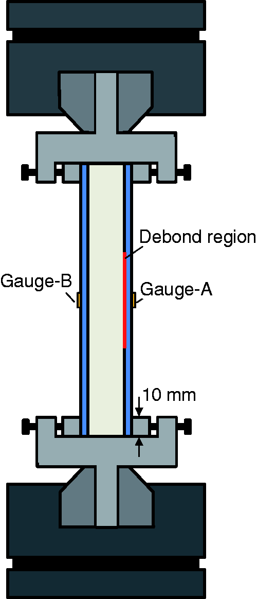
The composite sandwich specimens contained a foam core and composite face sheets. Polymethacrylimide foam was obtained from ROHACELL® (51WF), and the face sheets were graphite/epoxy composite laminates manufactured using two stacking sequences (i.e. [(0/90)2]S and [(0/90)3]S). The thicknesses of the composite face sheet tf in two lay-up configurations were 1.1 and 1.6 mm. The composite face sheets and foam core were then adhered together to form a sandwich structure by using FM73 adhesive film. During fabrication, a thin sheet of Teflon was inserted between the face sheet and the foam core to create a debond defect. In this study, the debond lengths Ld were designated as 10, 30, 50, 60 and 70 mm. The dimensions of the sandwich specimens are shown in Figure 1; the length of the specimens was 140 mm, and the gauge length was 120 mm. In addition, two strain gauges (Gauge A was on the debonded face sheet, Gauge B was on the bonded face sheet) were mounted on the specimens to measure the deformation configurations of the specimens under compressive loading. The compression tests were conducted using an MTS machine at a displacement rate of 0.002 mm/s. In the compression tests, both ends of the specimens were clamped on a fixture designed for these experiments, as shown in Figure 2. During the compression tests, the load and strain curves of the specimens were recorded and the failure specimens were examined using a microscope. At least three specimens for each case were fabricated and then tested until failure occurred.
Dimension of the debonded sandwich specimens. Schematic of experimental setup.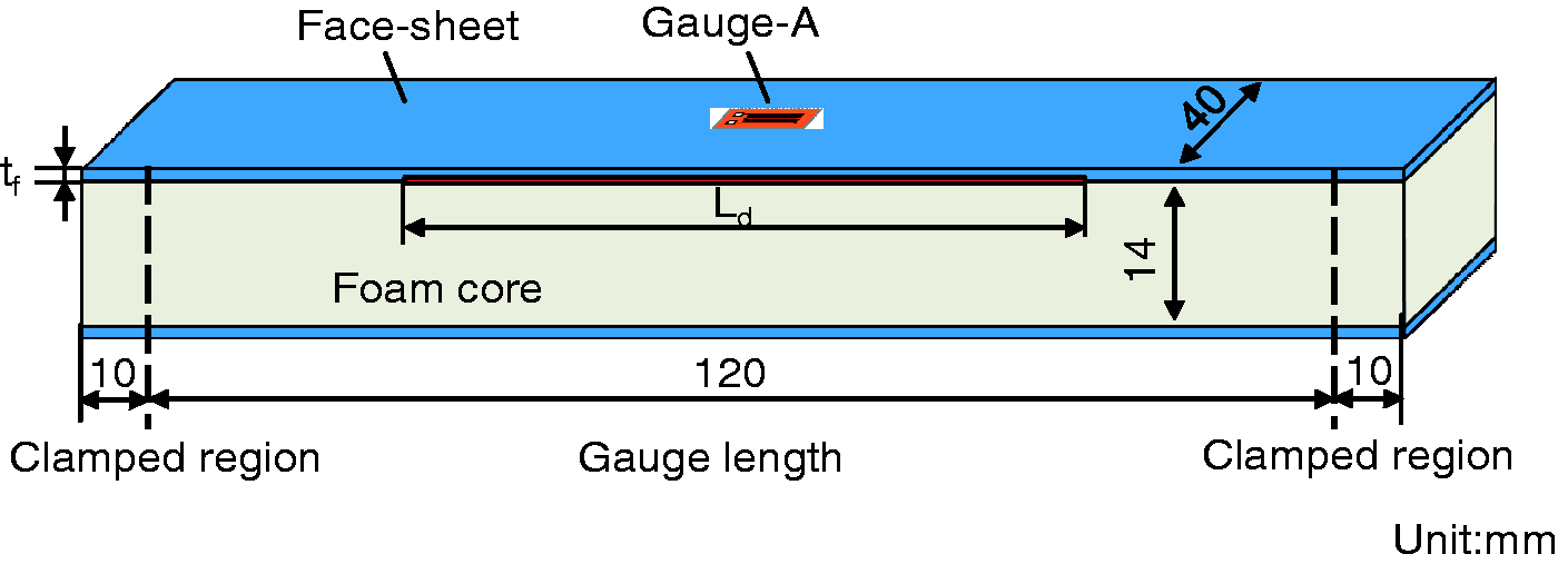
Experimental results
[(0/90)2]S composite sandwich specimens
The load deflection curves for a sandwich specimens with a 50-mm debond length are shown in Figure 3. Initially, both sides of the specimen were compressed. At a certain level of compressive loading, the debonded side (Gauge A) was subjected to tension; however, the bonded region (Gauge B) was under compression. The transition from compression to tension in the debond face sheet indicates the inception of local buckling, as shown in Figure 4(a). As the compressive load was increased monotonically, the buckling configuration of the debonded region became obvious and, eventually, the crack extended from the debond tip resulting in sudden failure as illustrated in Figure 4(b). The compression load corresponding to the maximum compressive strain (Gauge A) in the debond region was defined as the buckling load. Furthermore, the maximum compressive load during the tests was considered as the failure load of the specimen. It was found that after the local buckling occurs, the specimen with a 50-mm debond length can sustain more loading until the ultimate load is achieved. Observation of the failure specimens suggested that the separation of the face sheets and foam core caused by local buckling was the main failure mechanism.
Loading curves for the [(0/90)2]S specimens with debond length of 50 mm. Photos of the [(0/90)2]S specimens with debond length of 50 mm (a) local buckling, (b) debond extension.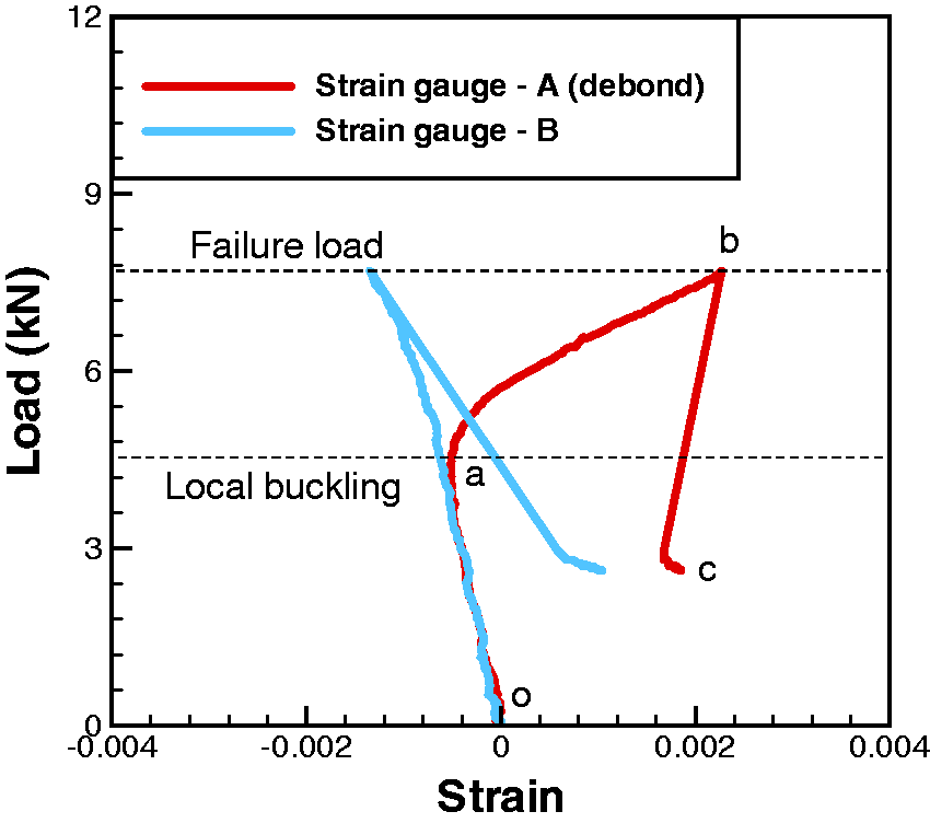
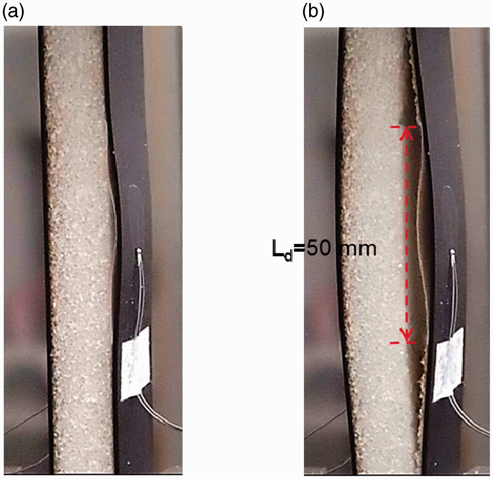
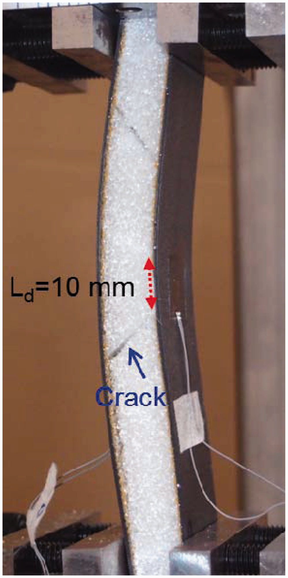
Figure 5 shows the load deflection curves for the specimens with a 10-mm debond length. Both face sheets were compressed before sudden failure occurred. Once failure took place, one face sheet abruptly became tensile, whereas the other face sheet remained compressed, indicating the inception of global buckling in the sandwich structures. The corresponding failure mechanism was foam core failure as shown in Figure 6. The crack was located within the foam core at an angle of 45° with respect to the loading direction. Moreover, when the debond length was short, the influence of the debond defect on the deformed configuration was minimal and global buckling could occur towards either the debonded side or bonded side. The results shown in Figure 6 indicate that global buckling occurred toward the bonded side. In summary, for the [(0/90)2]S composite sandwich specimens with a maximal debond length of 10 mm, the failure mechanism was global buckling; however, when the debond length exceeded 20 mm, the failure mechanism was local buckling.
Loading curves for the [(0/90)2]S specimens with debond length of 10 mm. Photos of the failure [(0/90)2]S specimens with debond length of 10 mm.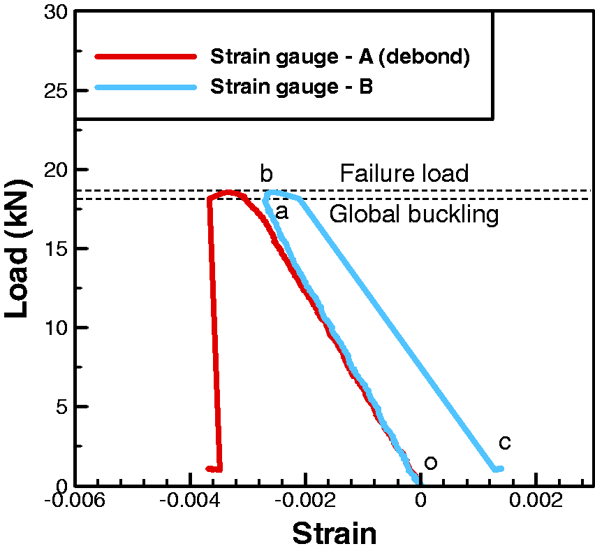
[(0/90)3]S composite sandwich specimens
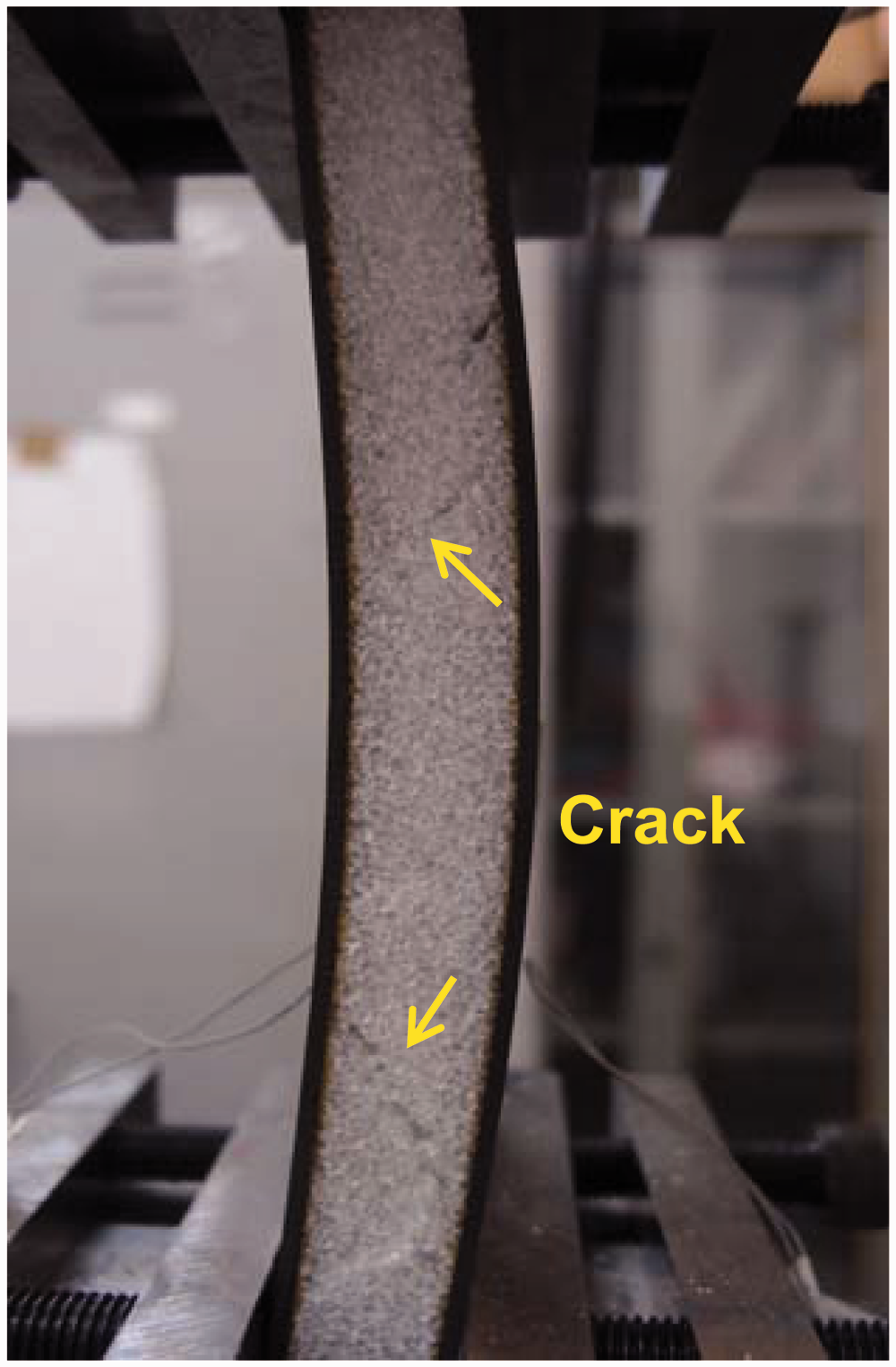
The load deflection for the [(0/90)3]S composite sandwich specimens without embedded debond defects is shown in Figure 7. Both face sheets of the sandwich structure were compressed until the initiation of global buckling, during which the gauge on one side of the specimen under maximal compression instantly became tensile. Simultaneously, the gauge on the opposite side remained compressed. When global buckling occurred, the buckling load and failure load were considerably close, and the failure mode was core failure associated with cracking at an inclination of 45° with respect to the loading direction as shown in Figure 8. For sandwich specimens with a 60-mm debond length, the load deflection curve is shown in Figure 9. These curves are similar to those for the [(0/90)2]S composite sandwich specimens with a 50-mm debond length as shown in Figure 3. For these two cases, the main failure mode was local buckling followed by debond extension. The experimental results regarding the failure modes of the sandwich specimens with various debond lengths and face sheet thicknesses are summarized in Table 1.
Loading curves for the [(0/90)3]S composite sandwich specimens without face sheet/core debond. Photos of the failure [(0/90)3]S composite sandwich specimens without face sheet/core debond. Loading curves for the [(0/90)3]S specimens with debond length of 60 mm. Experimental results of debonded composite sandwich specimens.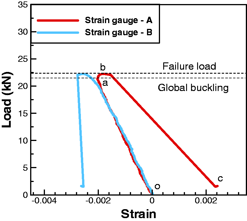
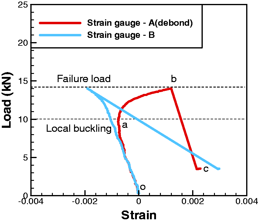

The foregoing experiments revealed that, for the sandwich specimens with [(0/90)2]s face sheets and a debond length of less than 10 mm and those with [(0/90)3]s face sheets and a debond length of less than 30 mm, the failure mode was global bucking together with core failure. Specimens that underwent such failures exhibited a higher buckling and failure load than those that exhibited local buckling. In other words, the sandwich structures with a short debond length and thick face sheet demonstrated a high compressive strength. Moreover, when the failure mode was core failure, the buckling and failure loads were considerably close and the corresponding values were not substantially influenced by the debond length. It should be cautioned that once global buckling occurred, the sandwich specimens could not endure further loading. Nevertheless, when the debond length was long, the failure mechanism seemingly became local buckling followed by creack extension from the debond tip. In such a failure mode, the failure load was considerably higher than the buckling load indicating that the specimens could withstand more loading after local buckling occurred. Furthermore, both the failure and buckling loads were sensitive to the debond length; an increase in the debond length corresponded to a decrease in the failure load. Regarding the face sheet thickness, at an identical debond length, sandwich structures with a thicker face sheet consistently withstood higher buckling and failure loading regardless of the type of failure mode.
Finite element analysis
To characterize the failure behaviors of the debonded sandwich specimens, a nonlinear FEA was conducted using the commercial code ANSYS. Figure 10(a) illustrates 2D FEA meshes where the sandwich specimen was modeled using high-order plane strain elements, plane 183. Furthermore, in the debond region, the contact elements (CONTA 172 and TARGE 169) were established on the interface to prevent contact surface penetration. Stress singularity occurring near the debond tips and the fine mesh, as shown in Figure 10(b), was generated near the tips. In order to simulate the compression tests shown in Figure 2, the degrees of freedom of the nodes within the clamp area in the lateral directions were designated to be zero such that there was no lateral translation and rotation occurring at the both end of the specimens. The material properties of the graphite/epoxy composites used in the analysis are shown in Table 2. In addition, information on the material properties of the foam core, which was obtained from the manufacturing company website [13] and employed in the analysis, is shown in Table 3. It is noted that the properties of foam core are quite compatible to those obtained from experimental data [14].
(a) Finite element mesh for the debonded sandwich specimens, (b) enlarged fine mesh near the debond tip. Material properties of graphite/epoxy composites. Material properties of PMI foam [14].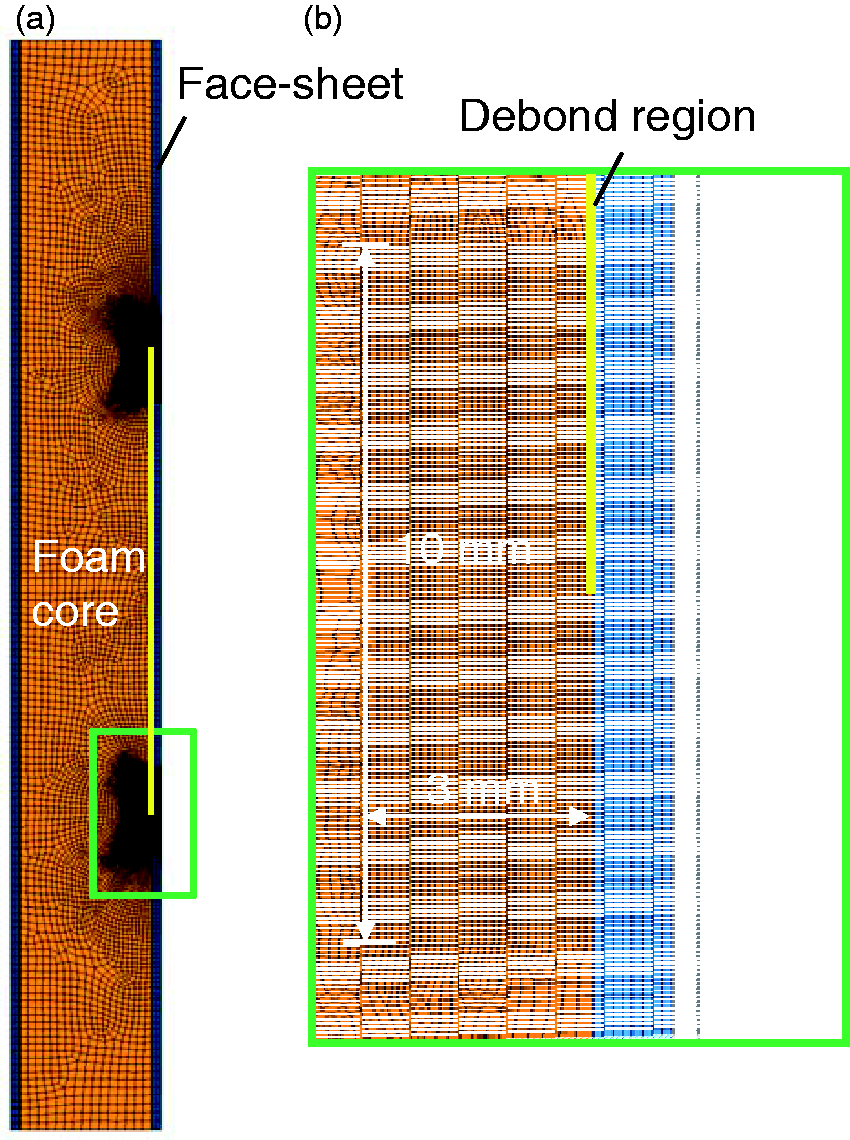


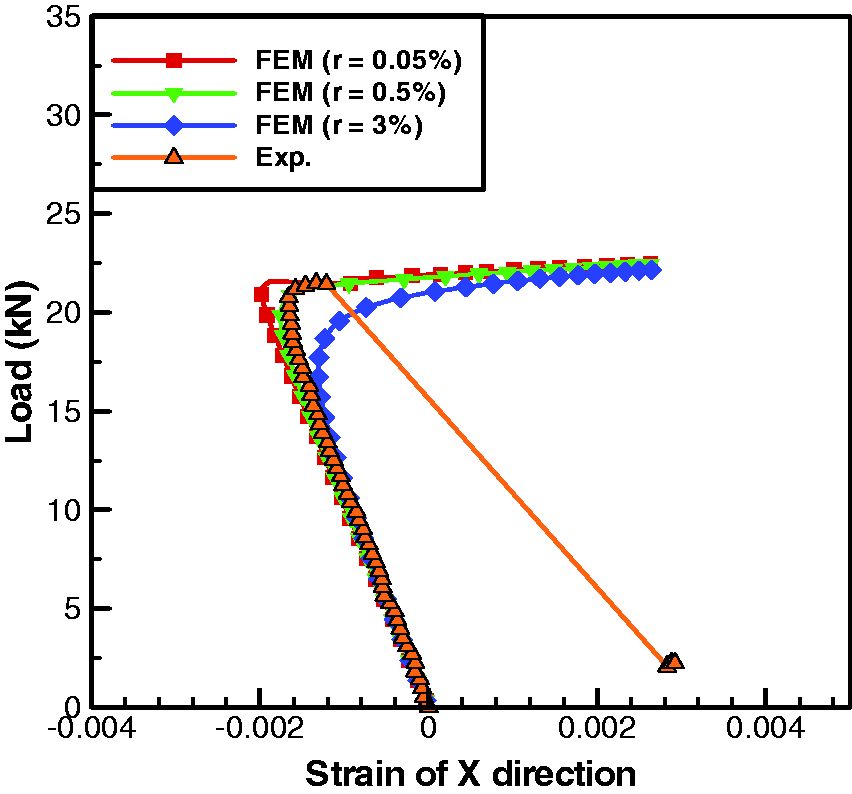
The FEA procedure comprised two steps. In the first step, a linear analysis was conducted to obtain the first buckling mode shape from, which an initial imperfection was introduced in the sandwich structure. The extent of the imperfection is defined as [8]
Definition of the debond amplitude in the FEA. The load deflection curves obtained from FEA with different values of r for the [(0/90)3]S composite sandwich specimens with debond length of 30 mm. Comparison of buckling loads obtained from simulation and experiments.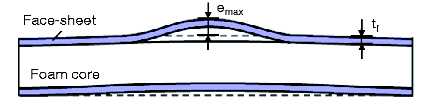

Failure predictions
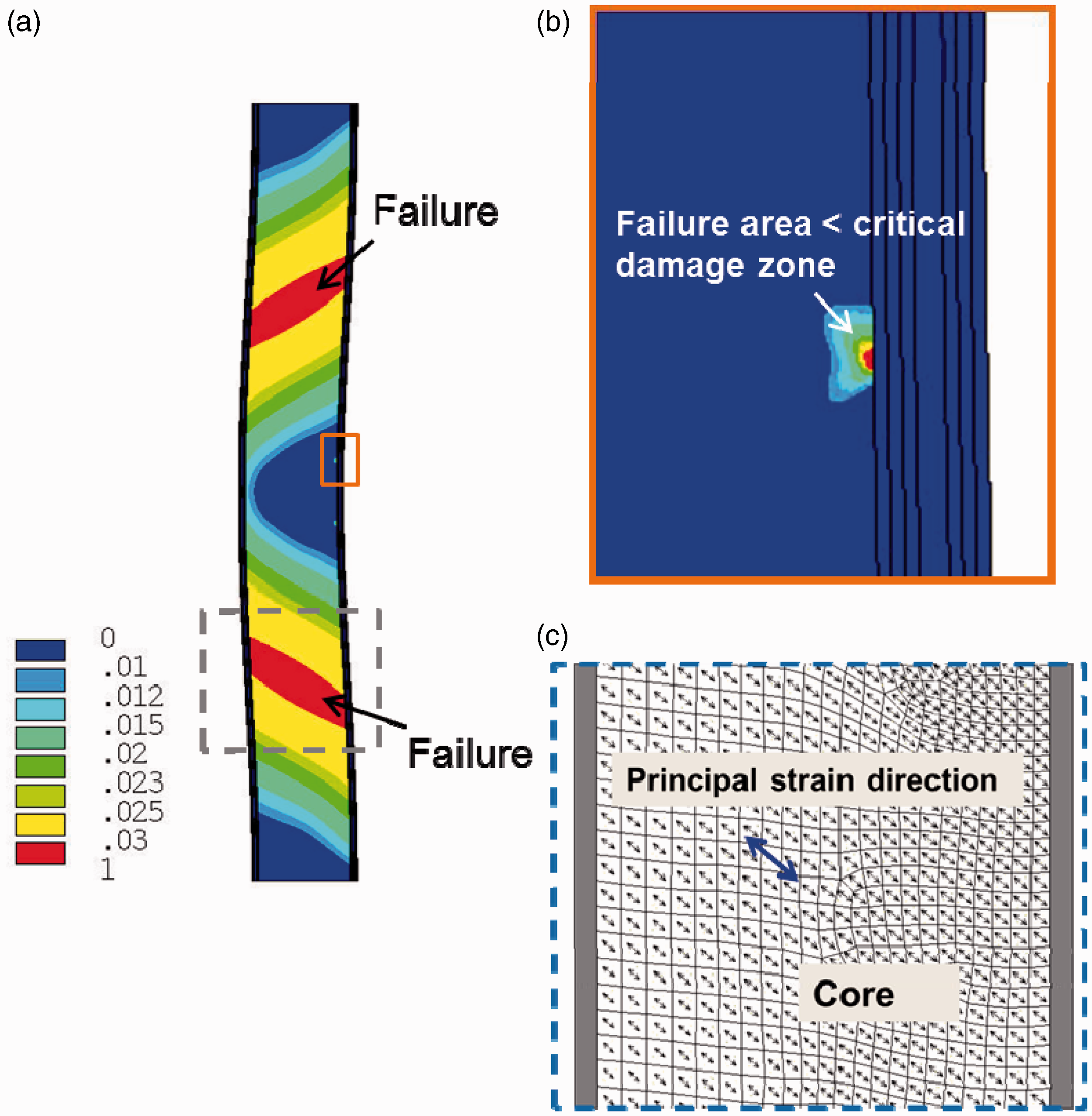
In addition to the buckling load, the failure behaviors of the debonded sandwich specimens were characterized using FEM analysis. The experimental results indicated that the debonded sandwich specimens failed through two main mechanisms, namely global buckling together with core failure and local buckling followed by the debond extension from the tips. In this study, the maximum principal strain criterion was adopted to predict failure modes. The maximum principal strain criterion was employed because the foam core is a brittle material and easily damaged under tensile deformation. Nevertheless, the debond tip exhibits stress singularity causing the strain components to be singular. Regarding the analysis, all materials were assumed to be linearly elastic. To assess the failure near the debond tip, the damage zone model proposed by Sheppard et al. [15] together with the maximum principal strain criterion was used. The advantage of using the damage zone model is that the area failure concept rather than the point failure concept are incorporated in failure predictions, thus enabling stress singularity near the debond tip to be avoided in the failure prediction. Therefore, the strain components of each element near the debond tip were calculated and then transferred into the principal directions. When the principal tensile strain of the element was greater than 0.03 (maximal tensile strain of the foam core), the area of the element was regarded as a damage zone. The summation of the damage zone near the crack tip was regarded as the failure index in the model predictions. The critical size of the damage zone was used to ensure that the predicted values fell in the ranges of the experimental variations. Here, the experimental data on [0/90]2s specimens with a 50-mm debond length were used as a benchmark and the critical damage zone size was determined to be 2.47 mm2. Figure 13 illustrates the distribution of principal strain in [(0/90)3]S specimens with a debond length of 60 mm. The failure area near the debond tip exceeded the critical damage zone size, and, thus, the debond defect extended from the tip, resulting in core and face sheet separation failures. These simulation results overwhelmingly corresponded with the experimental results shown in Figure 9. Figure 14 illustrates the distribution of principal strain in [(0/90)2]S specimens with a debond length of 10 mm and the direction of principal strain in the core. The failure area near the debond tip was smaller than the critical damage zone size, and the principal strain in the foam core reached the critical value; thus, the failure mode was foam core failure. The principal strain was oriented at an angle of approximately 45° with respect to the loading direction; this result is consistent with the experimental result shown in Figure 6. For each case, the failure area near the debond tip and the principal strain within the foam core were calculated to determine the failure load and the corresponding failure mode. The failure loads obtained from the simulation and the experiments are compared in Table 5. As illustrated, the failure modes predicted based on the failure criterion were consistent with the experimental observations. Moreover, the failure strengths derived from the criterion were nearly within the deviations of the experimental data.
(a) Distribution of principal strain in [(0/90)3]S specimens with debond length of 60 mm (b) distribution of principal strain near debond tip. (a) Distribution of principal strain in [(0/90)2]S specimens with debond length of 10 mm, (b) distribution of principal strain near debond tip, (c) direction of principal strain in foam core. Comparison of failure loads obtained from simulation and experiments.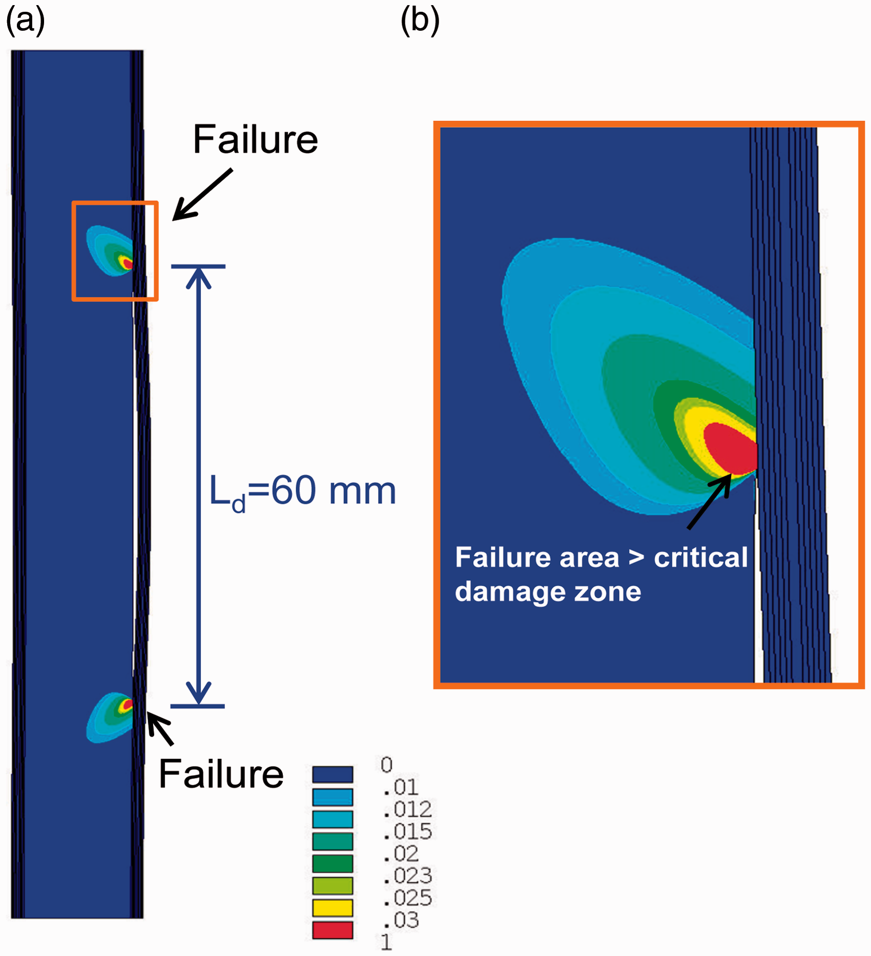

Conclusion
Debonded sandwich structures under compression loading were investigated experimentally and numerically. The effects of debond length and face sheet thickness on the failure mode and failure strength were characterized using FEA. Experimental results revealed that, when the debond length was increased or the thickness of the face sheet was reduced, the failure strength of the sandwich structure decreased. In addition, for the [(0/90)2]S specimens with debond lengths of less than 10 mm and the [(0/90)3]S specimens with debond lengths of less than 30 mm, the failure mode was global buckling followed by core failure. When the failure mode was global buckling, the failure strength was considerably close to the global buckling load. However, for specimens with longer debond lengths, the main failure mode was local buckling followed by crack extension from the debond tip. In such cases, the failure strength was relatively higher than the local buckling load indicating that the specimens could withstand more loading after local buckling occurred. The failure modes and strengths of the debonded sandwich specimens were characterized using the maximum principal strain criterion and damage zone model. The results indicated that, when the failure mode is core failure, the strength can be obtained using the maximum principal strain criterion. However, when failure is caused by debond extension, the failure strength can be determined using the damage zone model. The maximal discrepancy between the model predictions and experimental results regarding the specimens was approximately 15%.
Footnotes
Declaration of Conflicting Interests
The author(s) declared no potential conflicts of interest with respect to the research, authorship, and/or publication of this article.
Funding
The author(s) disclosed receipt of the following financial support for the research, authorship, and/or publication of this article: This research was supported by the National Science Council, Taiwan, under the contract No NSC101-2221-E-009-029-MY2, to National Chiao Tung University.