
Abstract
This article investigates the energy-absorbing behaviour of lightweight foam structures reinforced with aluminium and steel cylindrical tubes. Initial testing focuses on establishing the influence of the inner diameter to thickness ratio (D/t) of the metal tubes on their specific energy-absorption characteristics under quasistatic compression and low velocity impact loading. Following this, individual metal tubes are embedded in a range of crosslinked PVC foams, and the specific energy-absorption characteristics of these reinforced systems are determined. The effect of increasing the number of tubes on the energy-absorbing response of the tube-reinforced structures is also studied. The crushing responses of both aluminium and steel structures are then predicted using the finite element analysis package Abaqus/Explicit, and the predictions of the load–displacement responses and the associated failure modes are compared to experimental results. Agreement between the numerical predictions and the experimental data is good across the range of structures investigated, with the model accurately predicting the compression response and failure characteristics observed in the structures. It has been shown that the stiffness of the foam does not significantly alter the energy-absorbing behaviour of the stiffer metal tubes, suggesting that the density of the foam should be as low as possible, whilst maintaining the structural integrity of the part.
Introduction
In recent years, there has been an increasing drive towards the development of high-speed, lightweight and energy-efficient transport systems. A considerable amount of research has been undertaken to develop effective impact energy-absorbing systems for use in high-speed vehicles with key design requirement being to dissipate the crush energy efficiently, thereby protecting the occupants against the extreme loading conditions.
Previous work has shown that metallic tube structures subjected to axial loading are excellent for this purpose, due to their low cost, ease of fabrication and high efficiency in absorbing energy [1]. Research has shown that parameters, such as material properties, the geometry of the cross-section of tube, the diameter to thickness ratio and the loading conditions, can affect the energy-absorbing capability of a metallic tube [1,2]. It has been shown that thin-walled circular tubes frequently collapse in an axisymmetric mode (also known as a concertina mode) and nonaxisymmetric modes (known as a mixed or a diamond mode) [1].
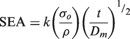
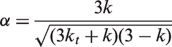
Alexander [1] developed a theoretical method to predict the mean collapse load for circular tubes failing in a concertina collapse mode. During crushing of a metallic tube, energy is primarily absorbed through irreversible plastic deformation mechanisms that dominate the progressive buckling process [3]. Jones conducted impact tests on a range of thin-walled tubes with circular and square cross-sections [2]. He concluded that in terms of energy absorption, a circular tube is the most efficient geometry. Gupta and Venkatesh [4] examined the effect of D/t ratio (mean diameter to thickness) on the energy-absorbing characteristics of aluminium tubes subjected to quasistatic and dynamic impact loading. They found that the mean collapse load and the specific energy absorption (SEA) increased with decreasing values of D/t. The SEA is given as [5]
Seitzberger et al. [8] studied the crushing characteristics of axially compressed steel tubes filled with aluminium foam. Their results showed that filling square tubes in this way improved their energy-absorption efficiency. In another study, Kavi et al. [9] investigated the energy-absorption behaviour of foam-filled thin-walled circular aluminium tubes. Here, it was shown that, in spite of the fact that foam filling resulted in a higher level of energy absorption than the sum of the contributions of the tube and foam on their own, it remains less effective in terms of increasing SEA than simply increasing the thickness of the tube walls. Del Piero and Pampolini [10] investigated the rate-dependent characteristics of polymeric open-cell foam subjected to uniaxial compression. They found that the average stress curves increased with increasing values of crosshead displacement rate from 0.1 to 100 mm/min. Found et al. [11] performed quasistatic compression tests to investigate the energy-absorption properties of a polyurethane foam sandwich panel with four fibre-reinforced plastic tubular inserts incorporated within the core by resin transfer moulding technique. They reported that by ensuring progressive brittle failure of the structure, higher SEA values were obtained. As a result of variations in the fibre distribution within the inserts, the sandwich tended to collapse in a catastrophic failure mode, leading to lower SEA values. Found et al. [11] also noted that a less labour intensive design of the structure would be preferable, given the fabrication process was rather difficult.
Given that the specific energy-absorbing capability of a circular tube is known to increase as the ratio of Dm/t decreases [4], a thick-walled tube with a small diameter (to keep a low Dm/t ratio) should, in principle, be efficient in absorbing energy. This suggests that effective energy-absorbing structures could be produced by embedding an array of small metal tubes in a low-density substrate, for example, a foam. It is possible that individual tubes fixed to the upper and lower skins may interact differently than multiple tubes fixed to the outer skins. It is also possible that lateral movement of the tubes during compression may cause localised buckling of the skins, a phenomenon that may be compounded by having many tubes positioned in close proximity.
A number of researchers [12–14] have investigated the axial crushing behaviour of circular aluminium tubes using numerical techniques and reported that the boundary conditions in numerical modelling influence the resulting crushing response. Al Galib and Limam [12] conducted both experimental and numerical studies on the crush behaviour of circular aluminium tubes subjected to axial compressive loading. In their models, they used a self-contact interface to prevent interpenetration between adjacent folds of the tube surfaces. Further, Yan et al. [13] stated that the effect of varying the friction coefficient is insignificant, since energy absorption due to friction is a small part of the total energy. Chen and Wierzbicki [14] investigated the axial crushing behaviour of single-cell, multicell and foam-filled thin-walled columns both analytically and numerically. A theoretical solution for the mean crushing force of multicell sections was shown to be in good agreement with the numerical predictions.
Although considerable effort has focused on studying the crushing behaviour of thin-walled tubes based on different materials and geometries, little attention has been focused on the possibility of using metallic tubes as reinforcements in foam-based sandwich structures. This article presents an experimental and numerical study on the axial crushing behaviour of circular metal tubes embedded in foams for use in lightweight energy-absorbing structures. The influence of varying the tube D/t ratio, the density of the foam and the possibility of developing foam structures based on an array of tubes is investigated.
Experimental procedure
Comparison of the quasistatic experimental and numerical SEA characteristics of 20 mm long individual aluminium tubes.
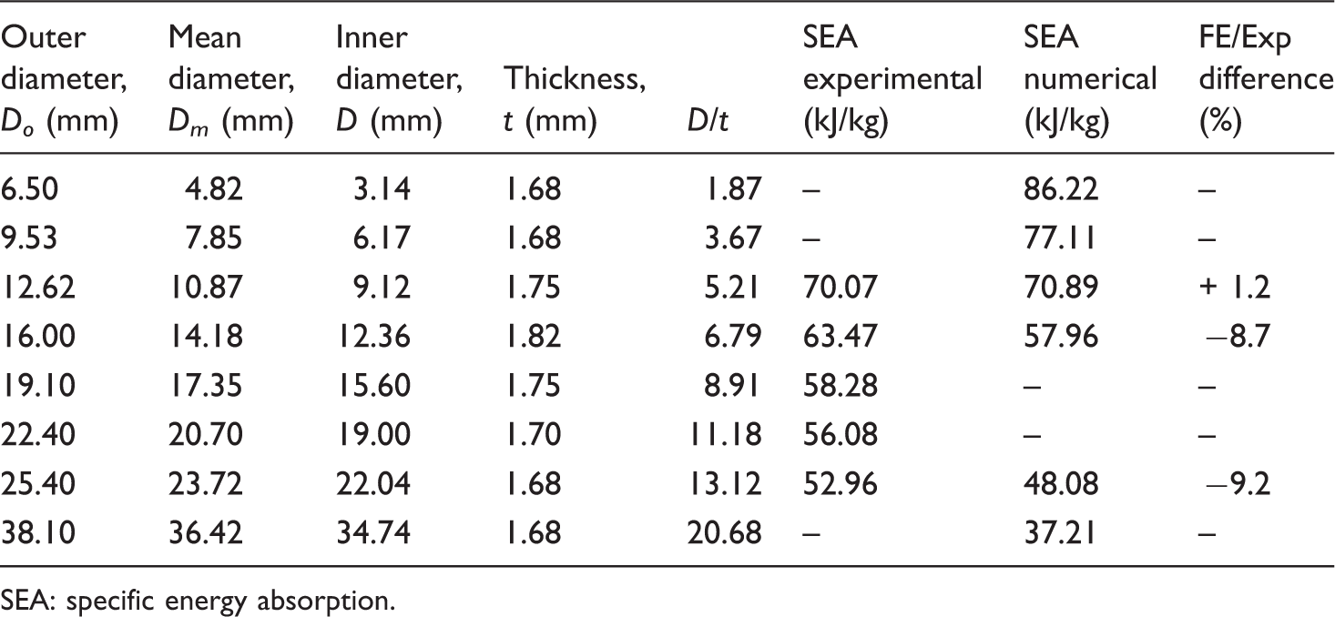
SEA: specific energy absorption.
Comparison of the quasistatic experimental and numerical SEA characteristics of 20 mm long individual steel tubes.
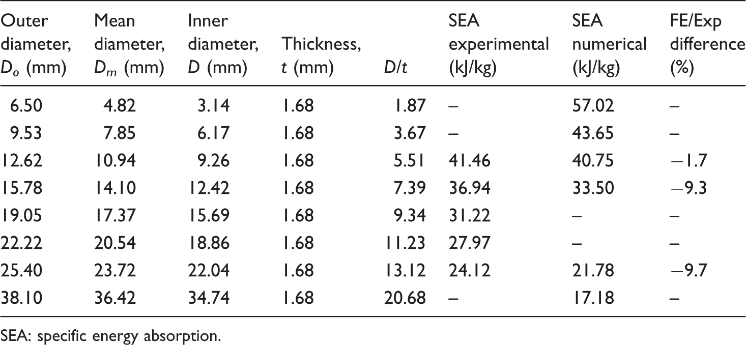
SEA: specific energy absorption.
Following this, single tubes were embedded in crosslinked PVC foams, with densities ranging from 38.3 to 224 kg/m3. Crosslinked PVC foams were selected to support the metal tubes, since they offer a relatively high compression strength and stiffness for a given density. The foams were manufactured and supplied in the form of flat panels by Airex AG. Additional tests were also undertaken on a low-density polystyrene (PS) foam with a density of 15.6 kg/m3. Prior to testing, a 12.6-mm diameter hole was drilled into a 50-mm square block of thickness 20 mm and either a steel or aluminium tube, with an outer diameter of 12.6 mm and a length of 20 mm, was inserted into the hole. In all cases, an interference fit of not more than 0.2 mm was ensured between the tubes and foams. In the final part of the experimental programme, between one and five 12.6 mm diameter tubes were embedded in 60 mm square blocks with a thickness of 20 mm. Experimental tests on the individual tubes and the tube-reinforced foams were also undertaken at dynamic rates of loading. Here, tests were undertaken using an instrumented impact carriage at a velocity of 5 m/s. The deformation response of the samples was recorded using a high-speed video camera. Reference [15] details the experimental set-up and test procedures in greater detail.
Finite element modelling
Numerical models were developed to simulate the mechanical response of the individual metal tubes, as well as the tubes embedded in foams at both quasistatic and dynamic rates of loading. Here, three materials are considered, these being the aluminium alloy, the mild steel and the polymer foam. The aluminium and steel tubes exhibited similar buckling modes when loaded in compression, whereas the foams deformed and compacted during compression. Given these different responses, different constitutive models are required to predict their respective behaviour. The material models described below were implemented in Abaqus/Explicit, and the predictions of the load–displacement responses and the associated failure modes were compared to experimental results.
Metal tubes
An isotropic elastic–plastic material model was used to simulate the mechanical response of the metallic tubes [16]. The total strain rate can be decomposed into an elastic component, 
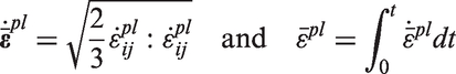
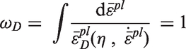
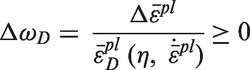
The rate-dependent material is assumed to obey a uniaxial plastic flow rule and the relationship of the equivalent plastic strain-rate, 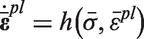
Temperature is not considered here as both testing and modelling are conducted at an ambient condition.
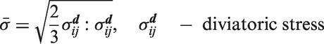
The uniaxial plastic strain, 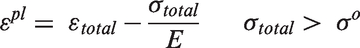
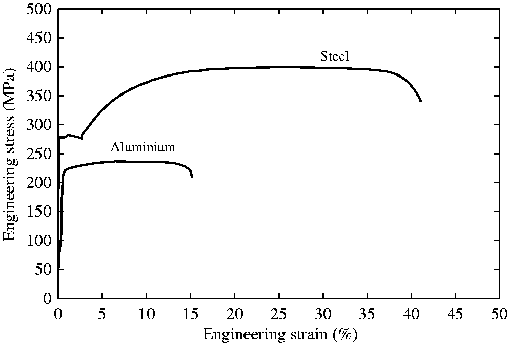
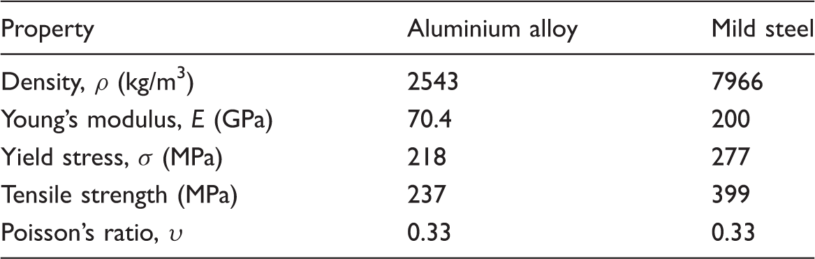
For the case where isotropic hardening is defined, the yield stress is given in tabular form as a function of plastic strain. For the aluminium alloy and steel materials used in this research, the isotropic hardening data were determined using data from the uniaxial tensile tests presented in Figure 1. The mechanical and elastic properties determined from these engineering stress–strain curves are presented in Table 3. The rate-dependent hardening curves are given by
Engineering stress–strain curves following tensile tests on a 12.62-mm diameter (D/t = 5.21) aluminium tube and a 12.62-mm diameter (D/t = 5.51) steel tube. Summary of the mechanical properties of the aluminium and steel tubes.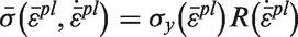
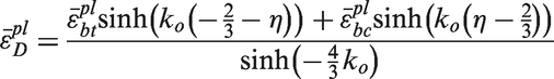
The ductile damage model is based on the equivalent fracture strain as a failure criterion. The initiation of damage in a ductile metal is due to the growth and nucleation of voids, which assumes that the equivalent plastic strain at the onset of damage is a function of stress triaxiality and equivalent plastic strain-rate [16,17].
The process of manufacturing metal tubes by extrusion leads to some form of “minor defect” or geometric imperfections in the finished product. This may have an effect on the deformation response of the metal tube, despite the fact that percentage of these imperfections is very small. Hence, a geometrical imperfection pattern was introduced in the “perfect” cylindrical model in order to trigger a buckling response before the critical load associated with failure of the material is reached. The geometrical imperfection pattern, or buckling modes, were obtained from the initial *Buckle Linear Perturbation step executed within Abaqus/Standard [16]. In order to request the results output, the buckling eigenmodes were included in the results file using the *Node File option with the Global = Yes parameter. Abaqus/Explicit [16] was then used to perform a further postbuckling analysis to account for the complex interactions introduced during progressive failure relating to the buckling collapse of the tube wall. Here, the predicted buckling modes were applied to the numerical model by introducing a geometrical imperfection through the tube wall, which is given by
Foams
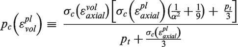
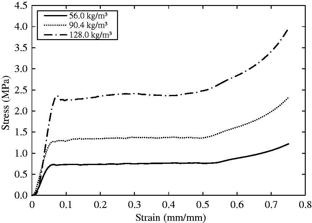
The foams were modelled using isotropic linear elasticity and crushable foam plasticity to describe their elastoplastic behaviour. The response of the foams was characterised by conducting compressive tests on blocks with dimensions of 50 × 50 × 20 mm3 and typical stress–strain curves are presented in Figure 2. The material input data required in the elastic region are the Young’s modulus and the Poisson’s ratio, where the latter was assumed to be 0.32 for all of the foams since the sensitivity studies showed that the simulations are not sensitive to Poisson’s ratios in the range from 0.25 to 0.35. The phenomenological yield surface for a closed-cell foam material, as described by Deshpande and Fleck [18], is given as
Typical stress–strain curves following quasistatic tests on crosslinked PVC foams with different densities.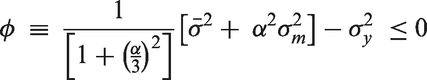
Geometrical model and contact conditions
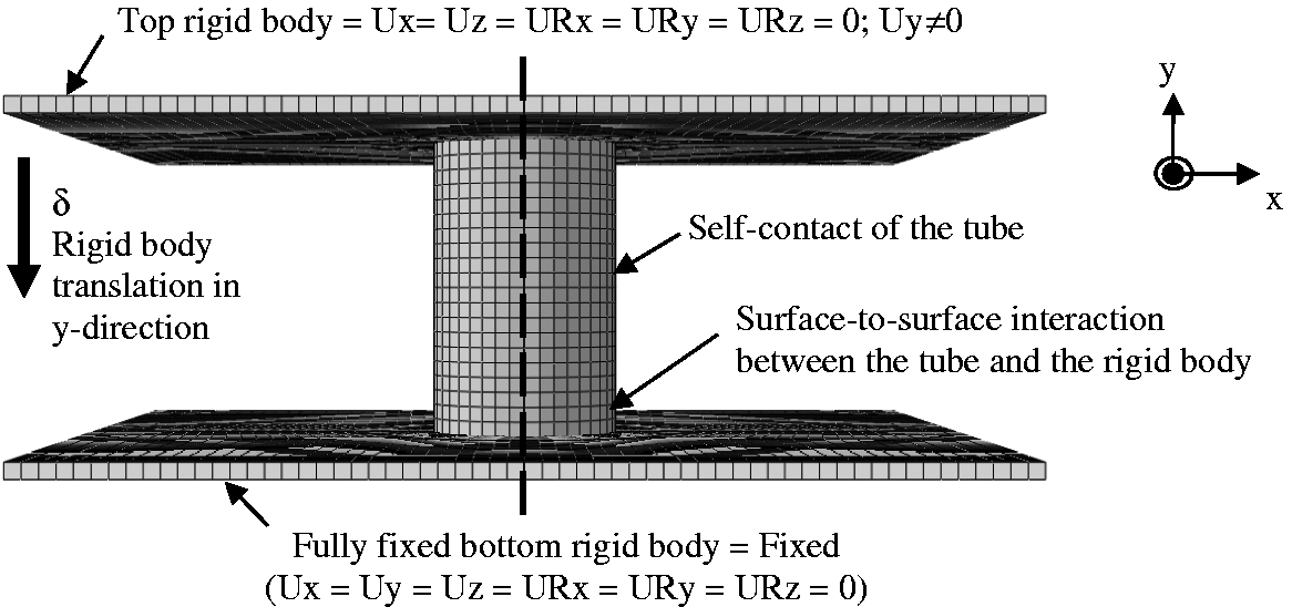
Due to geometrical symmetry, quarter models of each metal tube were constructed by applying suitable boundary conditions along each edge of the model in the x-axis and z-axis directions, as shown in Figure 3(a). This approach serves to reduce computational time and has been used by previous researchers when modelling the crushing response of square and circular cross-sections of steel tubes [8]. In the first stage of the modelling process, three tube diameters were simulated and validated using the experimental results, as shown in Tables 1 and 2. The tubes were modelled using 8-noded solid elements with reduced integration. Two 30-mm square plates with thicknesses of 1 mm, to represent the upper and lower platens, were defined as 3D discrete rigid bodies, as shown in Figure 4. The axial crushing process was modelled by displacing the top plate downwards in the y-direction (Figure 4) with the bottom plate being held stationary. The top and bottom ends of the tube were allowed to deform freely in all directions. In a subsequent part of this research program, one metal tube, with a diameter 12.62 mm, was inserted into a number of foams based on different densities, details of which are given in Tables 4 and 5. The foam materials were modelled using 8-noded solid elements with reduced integration. A small gap of 0.1 mm (Figure 3(b)) was introduced between the tube and the foam to avoid convergence problems. Figure 4 shows the contact condition for crushing of the metallic tubes. Due to the observed folding action of the tube, a frictional contact constraint was added to both the interior and exterior surfaces in order to prevent the tube wall from penetrating into itself. In order to model the metal tubes embedded in the foams, a further contact condition between the tube and the foam has to be considered. A coefficient of friction of 0.1 [19] was used between the tube and the rigid wall to achieve satisfactory agreement with the experimental results.
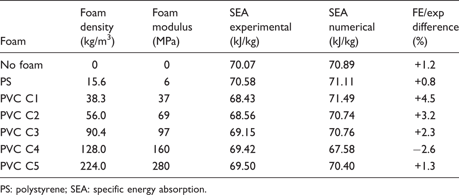
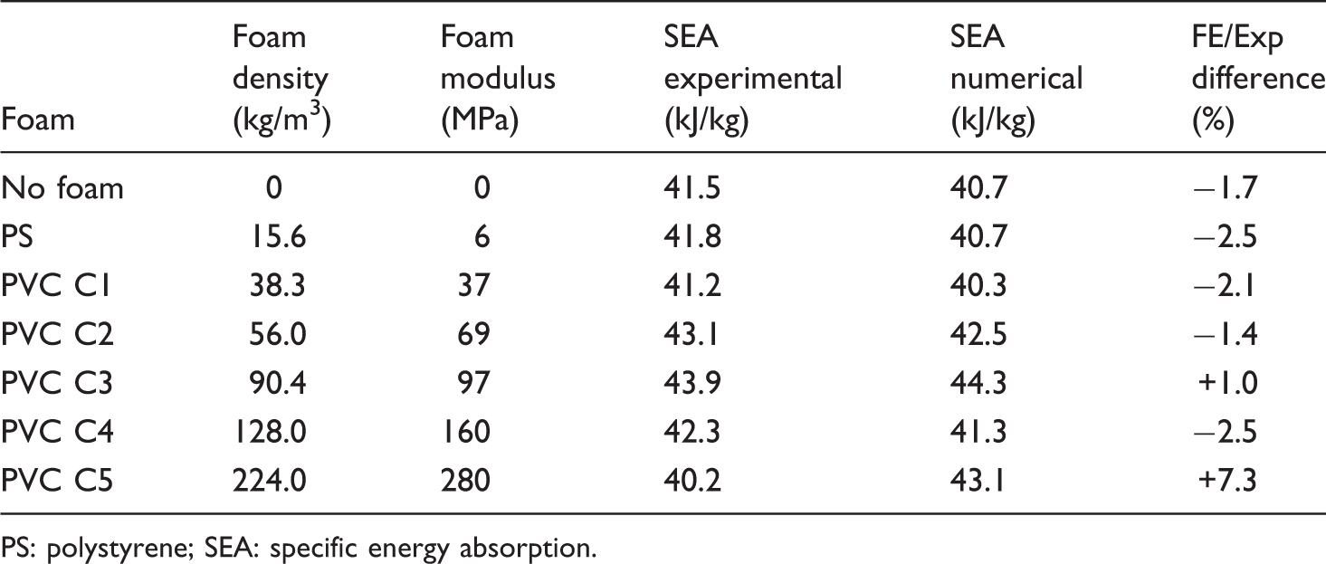
(a) A quarter model of a tube and (b) the cross-sectional view (shown this way simply for clarity) of a 12.62-mm metal tube in a foam block. Note that a small gap of 0.1 mm has been introduced between the tube and the foam. Loading and boundary conditions adopted in the finite element model. Summary of the quasistatic experimental and numerical values of SEA for individual 20 mm long aluminium tubes in foams of different density. PS: polystyrene; SEA: specific energy absorption. Summary of the quasistatic experimental and numerical values of SEA for individual 20 mm long steel tubes in foams of different density. PS: polystyrene; SEA: specific energy absorption.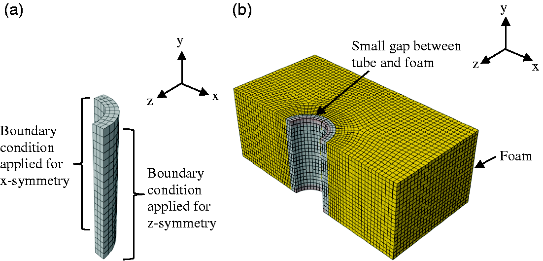
Mesh sensitivity analysis
A mesh sensitivity analysis was performed using a model of an aluminium tube specimen with a diameter of 12.62 mm and a length of 20 mm. The finite element (FE) model was meshed using four different mesh sizes, these being 0.5 mm (very fine), 0.8 mm (fine), 1 mm (medium) and 2 mm (coarse). Another parameter that contributes to the overall number of elements within the model is the number of elements through the thickness of the tube. Here, six models were studied, with each containing 100, 150, 600, 900, 2400 and 4800 elements. Figure 5(a) summarises the findings of this mesh sensitivity analysis, where the relationships between the number of elements and the predicted SEA, bottoming-out displacement and CPU time are shown. Clearly, the CPU time increases as the number of elements is increased. However, the bottoming-out displacement and the SEA values are very sensitive to the number of axial lobes. The symmetrical deformation modes of the models are shown in Figure 5, where Figure 5(b) and (c) indicates one lobe, whereas Figure 5(d) and (e) shows two axial lobes. It is clear that a coarse mesh size of 2 mm (100 or 150 elements) is not suitable for this case, as the tubes were unable to form the two axial lobes observed experimentally. This resulted in errors in the predicted SEA of up to 45% (for the model with 100 elements). Based on this observation, it is evident that increasing the number of elements from 600 to 4800 does not have a significant effect on the deformation shape, suggesting that mesh sizes in the range of 0.5–1 mm are appropriate for simulation. In the present study, 600 elements are used, since this value corresponds to the threshold at which the SEA and the force associated to bottoming-out tend to a constant value (see Figure 5(a)). Additionally, an element size of 1 mm was deemed to be appropriate, since it produces sufficiently accurate results in a short CPU time (45 min in the present case).
(a) Mesh-sensitivity analysis showing the number of elements required for convergence of the FE model for an aluminium tube of diameter 12.62 mm. Deformed shapes of tubes based on (b) 100 elements (mesh = 2 mm), (c) 150 elements (mesh = 2 mm), (d) 600 elements (mesh = 1 mm) and (e) 4800 elements (mesh = 0.5 mm).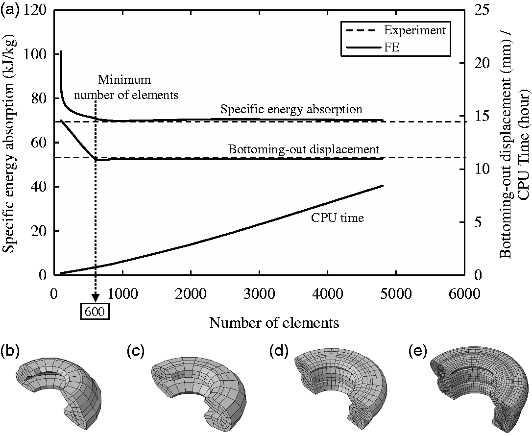
Results and discussion
Influence of D/t on SEA
The FE models were validated against the experimental data relating to the smallest, the largest and one of the intermediate-sized tube diameters, as given in Tables 1 and 2. Figure 6(a) compares the quasistatic experimental load–displacement curves for the 12.62 mm diameter aluminium and steel tubes with the predictions offered by the FE models. From the figure, it is evident that the load–displacement curves for the tubes show a steady increase in load until they reach the peak value. This is followed by a region of almost constant load, before the final bottoming-out of the sample at higher displacements. It should be noted that since perfect contact between the tube and the platens was assumed in all cases, the FE predictions slightly overestimate the measured stiffness. Beyond the elastic region, it is clear that the FE predictions are in good agreement with the experimental results for both types of tube.
Experimental and numerical force–displacement curves for 20 mm long and 12.62 mm diameter aluminium (D/t = 5.21) and steel (D/t = 5.51) tubes following (a) quasistatic and (b) dynamic loading.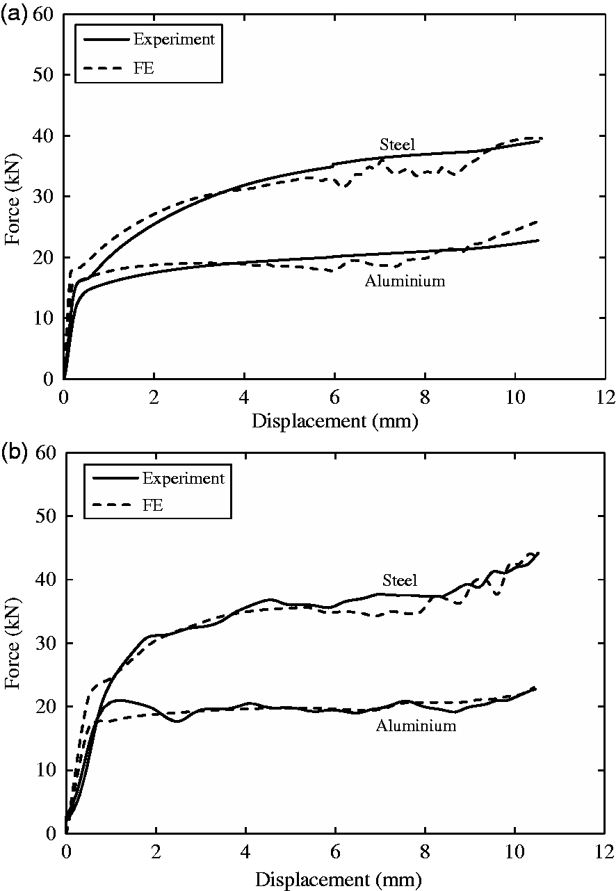
The predicted dynamic load–displacement curves for the 12.62-mm diameter aluminium and steel tubes are compared with their experimental counterparts in Figure 6(b). An examination of the numerical curves indicates that they are in close agreement with the experimental results for both types of tube. The FE models predict a smoother response than that associated with the test samples, since the latter exhibit an oscillatory response. This is due to ringing effects in the load cell following impact of the steel impactor on the stiff metal tube [15]. It is worth pointing out that when modelling the force–displacement curve of the steel tube under dynamic loading conditions (Figure 6(b)), there is a mild oscillatory response around the experimental value during the later stages of loading. This is likely to be due to the unstable response of local buckling collapse in the FE model, since steel shows a much higher resistance to impact loading. Despite this, the level of agreement between the experimental and FE predicted SEA values is very good.
The evidence in Figure 6 suggests that strain-rate effects are not significant for the aluminium. In contrast, an enhancement of approximately 10% is observed for the steel tubes, when tested under dynamic loading conditions. This evidence suggests that strain-rate effects are not significant for the aluminium alloy over the range of loading conditions tested here, whereas these findings indicate that it is important to define the strain-rate for accurate numerical modelling of the steel tubes.
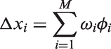
Figure 7 shows the variation of SEA with inner diameter/thickness, D/t, for both the aluminium and the steel tubes, where the dotted lines in the figure correspond to the FE predictions. The SEA of the structures was determined from the energy under the load–displacement curve up to the densification point and the initial mass of the specimen, which is given by
The variation of SEA with D/t for 20 mm long aluminium and steel tubes.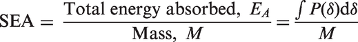
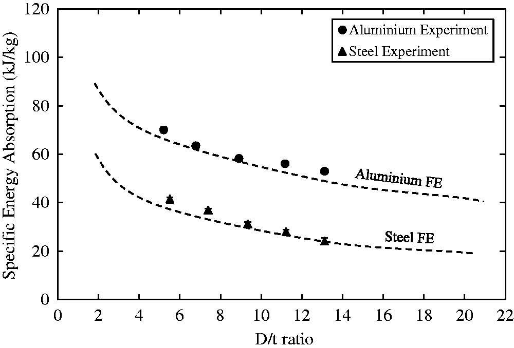
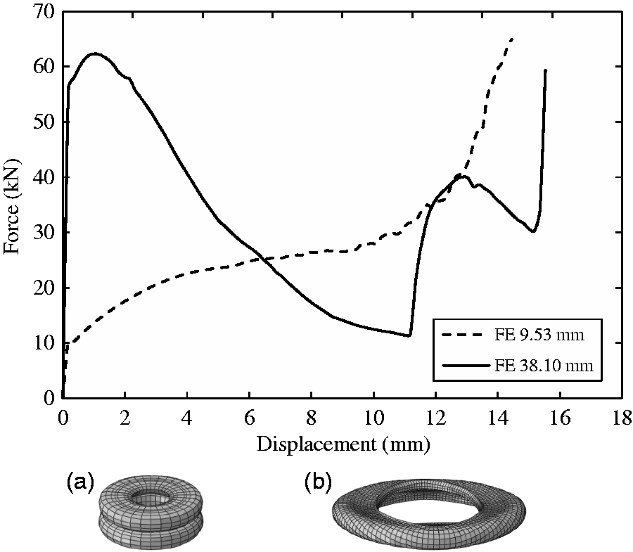
Figure 8 shows images obtained following experimental testing and FE modelling of the aluminium and steel tubes for a range of initial D/t values. It is clear that the deformation modes have been accurately predicted for all tube diameters, with buckling producing a ring shape, or what is often known as a concertina mode of collapse. These figures demonstrate that there is a very high level of agreement between the predicted and observed failure modes in the two types of tube. In the next stage of this research investigation, the FE models were used to further investigate the effect of varying the diameter-to-thickness ratio of the aluminium and steel tubes, and these results are summarised in Tables 1 and 2. Figure 9 shows the predicted load–displacement curves for steel tubes with diameters of 9.53 mm (D/t = 3.85) and 38.10 mm (D/t = 21.37). Also included in the figure are the corresponding deformation modes for both types of tube. The FE simulations predict that compression of the smaller tube will generate two wrinkles and that the larger diameter tube will exhibit a single wrinkle. This agrees well with findings reported by Jones [5], where it was observed that the number of wrinkles in a steel tube decreases with increasing tube diameter.
Comparison of the photographs and FE simulations of 20 mm long metal tubes with different diameters following quasistatic compression for (a) aluminium and (b) steel tubes. Predicted quasistatic load–displacement curves for 20 mm long steel tubes (a) 9.53 mm diameter (D/t = 3.85) and (b) 38.10 mm diameter (D/t = 21.37).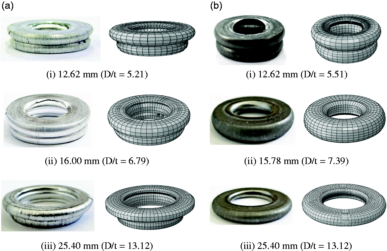
Influence of foam density on SEA
This part of the study considered the effect of embedding single metal tubes in a polymeric foam. The basic mechanical properties of the six foams investigated here are given in Table 5. Figure 10 shows experimental and predicted load–displacement curves following compression tests on the aluminium and steel tubes embedded in a crosslinked PVC foam with a density of 224 kg/m3. Also included in the figure are the load–displacement curves for the individual tube, as well as that for a foam sample having a similar volume to that of the combined tube + foam specimen. Generally, agreement between the experimental results and the FE data is very good, with all of the main features being captured by the model, including similar values of initial stiffness, peak load, plateau stress and bottoming-out displacement. In both the experimental and FE models, it is clear that the metal tubes dominate the response by absorbing most of the energy in these reinforced structures. At low and intermediate foam densities, the performance of the reinforced foam is roughly equal to that of the sum of the individual foam and tube in terms of SEA. In contrast, there is a small degree (<5%) of additional support due to the presence of the foam with a relatively high density, such as 224 kg/m3 as shown in Figure 10(b). This suggests that the presence of the foam may modify the collapse behaviour of the tube.
Experimental and numerical quasistatic load–displacement curves following tests on a 20-mm long, 12.62-mm diameter (a) aluminium tube (D/t = 5.21) and (b) steel tube (D/t = 5.51) in a foam with a density of 224 kg/m3.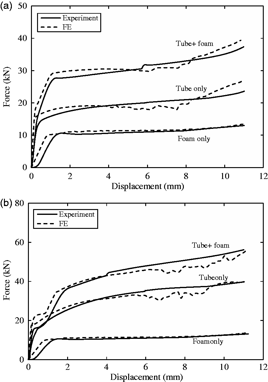
Figure 11 shows the predicted cross-sections of the aluminium and steel tubes embedded in the PVC foam following compression testing at quasistatic rates of loading. Given that an imperfection was introduced along the longitudinal axis of the tube, it is possible that the tube could penetrate into the foam. This was prevented by introducing a small gap between the tube and the foam in FE models, as shown in Figure 3(a). A comparison of these images with those shown previously in Figure 8(a)i and (b)i indicates that the modes of deformation and failure are similar for both the plain and embedded tubes. This suggests that the foam does not significantly modify the response of the tube and suggests that the former merely acts as a substrate to secure the position of the tubes. The density of the foam should therefore be as low as possible, whilst serving to hold the tubes in the required locations during loading.
Cross-sections of the deformed shapes of 20 mm long tubes (outside diameter = 12.62 mm) embedded in a PVC foam with a density of 224 kg/m3 (a) aluminium tube (D/t = 5.21) and (b) steel tube (D/t = 5.51).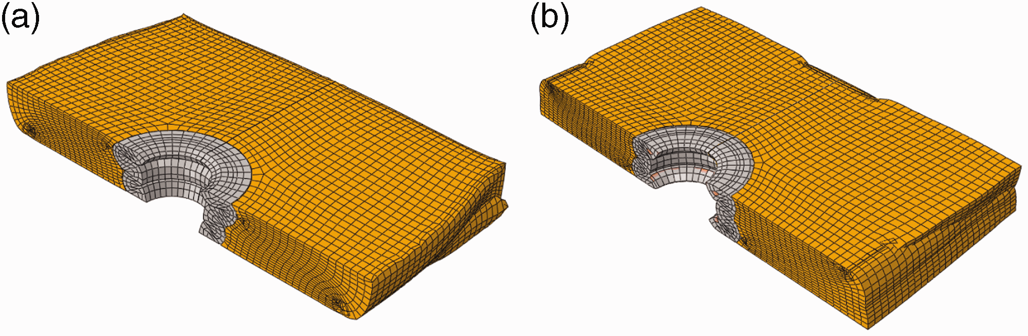
The experimental results and the FE predictions for the SEA of the tubes under quasistatic loading are given as a function of foam modulus in Figure 12. As noted in Table 5, these tests were undertaken on foams with densities ranging from 15.6 to 224 kg/m3. Here, the energy absorbed by the individual metal tube was estimated by removing the contribution associated with the foam [15]. The resulting value of energy was then divided by the mass of the metal tube to yield an effective SEA value for the tube on its own. Also included in the figure are the values resulting from the previously reported tests on the individual metal tubes, that is, those tubes that were not embedded in a foam. These particular points are shown on the y-axis of the figure. From the figure, it is evident that the values of SEA for both types of tube do not vary with foam modulus. Additionally, it is clear that the FE models accurately predict the SEA values of these embedded tubes, with the greatest error being approximately 8%. These results support the conclusion that the foam functions only to maintain the tubes in place during loading and that it does not significantly modify or improve their performance.
The variation of the quasistatic experimental and FE values of SEA for aluminium and steel tubes. The contribution of the foam has been removed.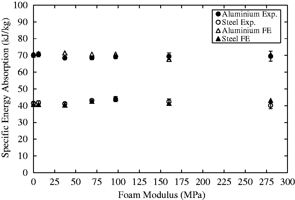
Figure 13 compares the variation of the quasistatic and dynamic (experimental) values of SEA with foam density for the two types of tubes. Once again, the contribution of the foam has been removed in order to yield effective SEA values for the individual tubes. As before, the properties of the foam do not have a significant effect on the energy-absorbing characteristics of the metal tube. Here, it is evident that the SEA values exhibited by the aluminium tubes at dynamic rates are almost identical to their corresponding quasistatic values, indicating that there is a lack of rate sensitivity in the response of this material. In contrast, the steel tubes exhibit a small level of rate sensitivity (approximately 10%) reflecting the trends observed previously in Figure 6.
The variation of the experimentally determined quasistatic and dynamic values of SEA with foam density. Aluminium (outside diameter = 12.62 mm, D/t = 5.21) and steel (outside diameter = 12.62 mm, D/t = 5.51).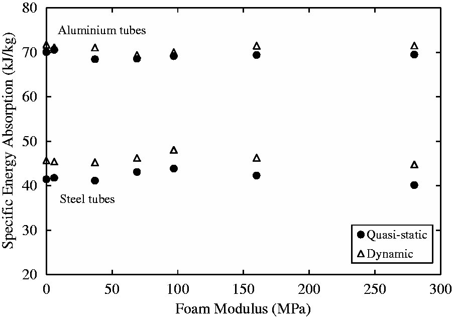
FE models were developed to predict the response of the aluminium and steel tubes embedded in foam at impact rates of loading. Figure 14 shows typical load–displacement curves (experimental and predicted) following impact tests on aluminium and steel tubes embedded in a 38.3-kg/m3 crosslinked PVC foam. Also included are the responses of the individual constituents, that is, the tube and the foam. Despite some small oscillations in the FE prediction during the later stages of the load–displacement curve, the predicted SEA values are again in a good agreement with the experimental results, where the average differences between the predicted and measured values for the aluminium and steel are approximately 4 and 7%, respectively.
Predicted and measured dynamic load–displacement curves for the metal tubes, a low-density foam (density = 38.3 kg/m3) and the combined tube plus foam: (a) aluminium (outside diameter = 12.62 mm, D/t = 5.21) and (b) steel (outside diameter = 12.62 mm, D/t = 5.51).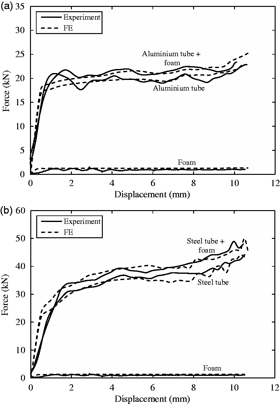
Tests on multitube foams
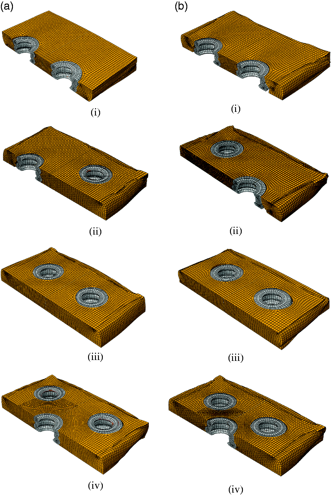
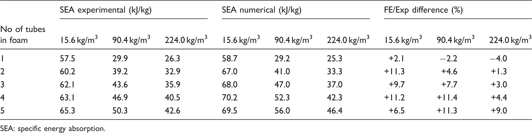
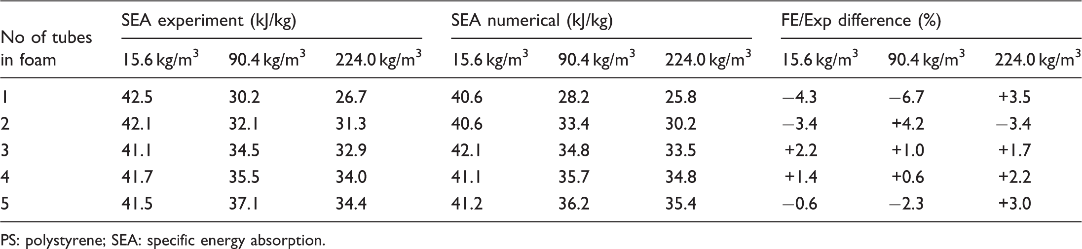
The final part of this study investigated the effect of increasing the number of tubes on the quasistatic energy-absorbing response of these reinforced foam structures. Here, between one and five 12.6-mm diameter metal tubes were embedded into 20 mm thick, 60 mm square foam blocks, details of which are given in Tables 6 and 7. Figure 15 shows a series of measured and predicted load–displacement curves for multitube systems embedded in a foam with a density of 224 kg/m3. As before, the FE models overestimate the initial stiffness in almost all cases, most particularly for the case of the aluminium systems. However, it can be seen that the overall trends in both the experimental and FE predictions are generally similar. Any differences between the experimental data and the model may, in part, be due to the fact that the buckling resistance of the tubes is very sensitive to the presence of imperfections within them. The resulting SEA values were calculated based on the total mass of the test samples, that is, no attempt was made to remove the contribution associated with the foam. As expected, increasing the number of tubes in a foam sample serves to increase the overall SEA of the structure. For example, the SEA of the aluminium-PS (density = 15.6 kg/m3) system increases from 58 to 65 kJ/kg as the number of tubes is increased from one to five. Similar trends are apparent in the 224 kg/m3 foam, where increasing the number of tubes serves to increase the SEA from 26 to 43 kJ/kg. It is interesting to note that the SEA of the PS structure containing five tubes is similar to that of the plain tube, suggesting that the response of the metal tubes completely masks that of the foam. A closer inspection of Figure 16 leads to the conclusion that the buckling response of the multiple tubes embedded in the foam is similar to that of individual tubes, Figure 8(a)i and (a)ii, and suggests that a simple rule of mixtures approach could be used to estimate the energy-absorbing capability of foams reinforced with a multitude of metal tubes.
Predicted and measured force–displacement curves for increasing numbers of 12.62 mm diameter metal tubes in a PVC foam with a density of 224 kg/m3 (a) aluminium tubes (D/t = 5.21) and (b) steel tubes (D/t = 5.51). Cross-sections of deformed foam samples based on increasing numbers of tubes in a PVC foam with a density of 224 kg/m3 (a) aluminium tubes (D/t = 5.21) and (b) steel tubes (D/t = 5.51). Summary of the SEA values (experimental and numerical) for PS and PVC foams containing between 1 and 5 aluminium tubes. SEA: specific energy absorption. Summary of the SEA values (experimental and numerical) for PS and PVC foams containing between 1 and 5 steel tubes. PS: polystyrene; SEA: specific energy absorption.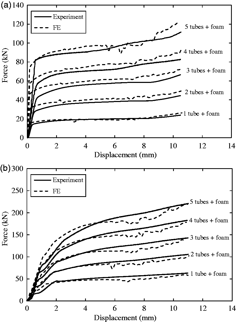
Conclusions
FE models have been developed to investigate the compressive properties of tube-reinforced foams under conditions of axial crushing. Data from tests on individual aluminium and steel tubes show that the energy-absorbing capability of the tubes decreases with increasing D/t. The values of SEA for the aluminium tubes were similar under quasistatic and dynamic loads. In contrast, a small increase in SEA was observed in the dynamically loaded steel tubes. The predicted deformed shapes of the metal tubes corresponded closely with the experimental observations, supporting the view that the model accurately predicts the response of these simple structures. It has been shown that the foam does not significantly modify or enhance the performance of the tubes above that observed following tests on the individual tubes. This suggests that the density of the foam should be low, whilst being sufficient to maintain their precise positioning within the foam and the overall integrity of the associated sandwich structure. Finally, the effect of increasing the number of the tubes on the energy-absorbing response of these structures has been investigated. The experimental results, together with the FE simulation again suggest that the contribution of the foam does not significantly enhance the performance of the reinforced foam. It is proposed that these models can be used for further parametric studies to assist in designing and optimising the structural behaviour of lightweight energy-absorbing sandwich structures.
Footnotes
Acknowledgements
The authors are grateful to Airex AG for supplying the crosslinked PVC foams and to the Malaysian Government for the Research Studentship (RA Alia).
Declaration of Conflicting Interests
The author(s) declared no potential conflicts of interest with respect to the research, authorship, and/or publication of this article.
Funding
The author(s) received no financial support for the research, authorship, and/or publication of this article.