
Abstract
An experimental investigation on sandwich composite materials composed of glass-fiber face sheet and polyvinyl-chloride foam core has been carried out. The research demonstrates improvement in mixed-mode delamination fracture toughness values of samples under mixed-mode bending condition. The improvement is recorded with addition of a certain percentage by weight of multiwalled carbon nanotubes in comparison to conventional samples. An easy and cost-effective methodology of multiwalled carbon nanotube insertion through sonication of epoxy resin followed by mixing with hardener and vacuum resin infusion technology for manufacturing of sandwich composites has been utilized in this study. The study also identifies the optimum weight percentage of multiwalled carbon nanotube addition in the resin system for maximum performance gain in mixed-mode fracture toughness. The results of observations in this study have been supported by field emission scanning electron microscope studies as well as high-resolution transmission electron microscope analysis.
Introduction
In spite of high strength to weight ratio and many other advantages of sandwich composite structures, interfacial face-core delamination remains as one of the major challenges for these types of structures. Sandwich composites are subjected to mixed-mode delamination failures in almost all practical loading situations due to significant differences in material properties and thickness of the materials used for the face sheet and the core. Interfacial face-core debonding is considered to be one of the major causes for loss of structural integrity and/or even catastrophic collapse of these structures. Definition of “interface” for a sandwich composite structure is an important point to be noted here. Since the resin infiltrates into the micropores of foam core and also in between the glass fibers, there is no distinct interface region as observed in a metal–metal bond. Typically, the interface region between glass fiber-reinforced plastics (GFRP) face sheet and the polyvinyl chloride (PVC) foam core is formed as a result of bonding between resin system of the face sheet and PVC foam core. Thus, the interface in this type of sandwich is a smeared layer of glass fiber strands, the resin system (used for GFRP face sheet) and some regions of PVC foam core. As a result, there is no distinct layer of resin system bonding and separating out the face sheet and core which may be separately termed as an interface region.
Research literature has been focused on improving the interfacial delamination resistance of these structures. Examples include use of shear key insertions [1,2], stitching technology [3–6], z-pin fiber insertions [7–12], peel stoppers [13–14] and also use of multiwalled carbon nanotube (MWCNT) in epoxy resin mix to promote better bonding [15–37]. In this research, the effect of MWCNT in the epoxy resin mix has been investigated to determine performance improvement of the mixed-mode response of glass fiber face sheet and PVC foam core sandwich composites.
The use of MWCNTs for toughening resin systems has become a popular practice after the seminal paper by Iijima [17]. The use of several types of CNTs through different methodologies for improvement in fracture characteristics is typically limited to laminated composites in literature. In case of composite laminates, improvements of 60% and 17% in interlaminar fracture toughness have been achieved with aligned CNTs and sprayed MWCNT, respectively [22,23]. Another work on CFRP laminates recorded an improvement of 32% in interlaminar toughness by spraying MWCNTs on Teflon coated peel cloth and transferring them to woven prepregs [31]. In laminated composites, improvements of fracture toughness by 23% and 20% are reported with the use of 0.5 wt% and 0.1 wt% of functionalized CNTs and MWCNTs, respectively [30,29] in comparison to conventional cases. In hybrid nanocomposite, Karapappas et al. [35] recorded an increase of 60% in mode I fracture toughness with 1 wt% MWCNT and 75% increase in mode II fracture toughness (GIIC) with 0.5 wt% MWCNT of resin in comparison to the neat epoxy reinforced with carbon fibers only. Garcia et al. [36] used vertically aligned CNTs (VACNTs) at the interface between the plies of carbon composite laminate and reported an improvement of 50% in mode I fracture toughness and as high as 200% in mode II fracture toughness values. In nanocomposites, an enhancement in mixed-mode fracture toughness approximately by 31% for mode ratio 1 with 0.5 wt% of MWCNT has also been reported [37]. The above set of literature shows different percentage increase in performance with addition of MWCNT in nanocomposites or laminated composites only. It should be pointed out here that the percentage gain in fracture performance of the samples depends largely on the type of resin system used, type of functional group of the MWCNT and also on the material characteristics of the constituent materials which are to be bonded with the resin system. In fact, MWCNTs not only toughens the resin system but also infiltrates within the adjacent constituent materials that are to be bonded and thereby improves mechanical performance.
Literature report use of several types of CNTs for improvement in fracture characteristics of nano, hybrid or laminated composites only. But to the best of the authors’ knowledge, there appears to be no work done on influence of MWCNTs on mixed-mode fracture toughness of glass-epoxy (G/E) and PVC core sandwich composites. This manuscript strives to investigate the influence of MWCNTs on mixed-mode fracture of G/E–PVC core sandwich composite along with determination of optimum percentage of MWCNTs. A sandwich composite differs significantly from laminated composites, since it consists of at least two different materials (having significant differences in material and geometrical properties). Thereby the characteristics of a bi-material interface (present in sandwich composites) cannot be directly extrapolated from results obtained from single-material interfaces (as present in laminated composites).
This manuscript demonstrates improvement in fracture performance of sandwich composite with different wt% of MWCNT addition on different mode mixities (measured by the ratio of mode II to mode I fracture toughness values) of mixed-mode bending (MMB) samples. In addition, the methodology used in this research work for MWCNTs addition in epoxy resin is much simpler than that used by other researchers for addition of MWCNT in resin mix for composite laminate manufacture.
Details about the process of manufacturing are presented in Process of manufacture section along with HRTEM investigations. Experimental investigation section describes the experimental investigations carried out with the manufactured samples; Results and discussions section discusses the results as obtained in experimental investigation (MMB test) and micrograph studies (FESEM) for samples with and without MWCNT; Conclusions section provides discussion and conclusion to the manuscript including possibilities of future work.
Process of manufacture
Epoxy resin (Araldite CY 230-1 IN of Huntsman Advanced Materials with 1300–1800 mPa s viscosity and 1.13–1.16 g/cc specific gravity at 25℃) and MWCNTs (Cheap Tubes Inc.) with outer diameter less than 8 nm, inside diameter 2–5 nm, individual length of 10–30 µm, specific surface area 500 m2/g, bulk density 0.27 g/cc) are used. The above mentioned resin and MWCNTs are thoroughly mixed with an ultrasonic liquid processor (OSCAR make SONAPROS PR- 500 MP processor with frequency (20 ± 3) kHz, ultrasonic power 500 W and 18 mm Ø Titanium horn) for 2.5 h intermittently (15 s on and 5 s off for the first hour, 10 s on and 5 s off in second hour and 5 s on 5 s off for the last half an hour) at 60% amplitude maintaining room temperature (25℃). The process of ultrasonication of the same epoxy resin has been repeated with 0.1 wt%, 0.2 wt%, 0.3 wt%, 0.4 wt% and 0.5 wt%, respectively. Hardener (Aradur HY 951 IN of Huntsman Advanced Materials with 10–20 mPa s viscosity and 0.97–0.99 g/cc specific gravity at 25℃) in 10 wt% of epoxy resin is mixed with the mixture after sonication by stirring at 150 for 15 min.
Dispersion of MWCNTs at different weight percentages of epoxy resin is studied through HRTEM analyses. Hardened mixtures of sonicated epoxy resin and hardener are trimmed with LEICA EM trim and cut to 100 nm thick samples using LEICA EMFCS Ultra-Microtome machine. These samples are then placed on copper grids and examined through JEOL JEM2100 HRTEM with 80 k magnification at an operating voltage of 200 kV. HRTEM images in Figure 1 for resin samples with MWCNTs (0.2–0.4 wt% of epoxy resin) can be observed to show relatively good dispersion; however, the optimum wt% of MWCNT for the best value of mixed-mode fracture toughness cannot be stated clearly from visual observations. Resin samples with MWCNTs for 0.1 wt% and 0.5 wt% of resin demonstrate low dispersion and agglomeration effects, respectively. An efficient dispersion or agglomeration of MWCNTs in resin is related to relative van-der Waals forces, curvature, and relative surface energy between MWCNTs and resin. In this research, ultrasonication is done to overcome the attractive forces, but MWCNTs may reagglomerate on discontinuation of external forces after sonication [21]. It should be noted in here that efficient load transfer between the constituent materials of the face sheet and the core is determined by the better nanotube–matrix interface properties and primarily influenced by the optimum dispersion of MWCNTs in the nanocomposites [22].
HRTEM images of samples with different weight percentage of multiwalled CNT: (a) 0.1 wt% CNT, (b) 0.2 wt% CNT, (c) 0.3 wt% CNT, and (d) 0.4 wt% CNT, (e) 0.5 wt%.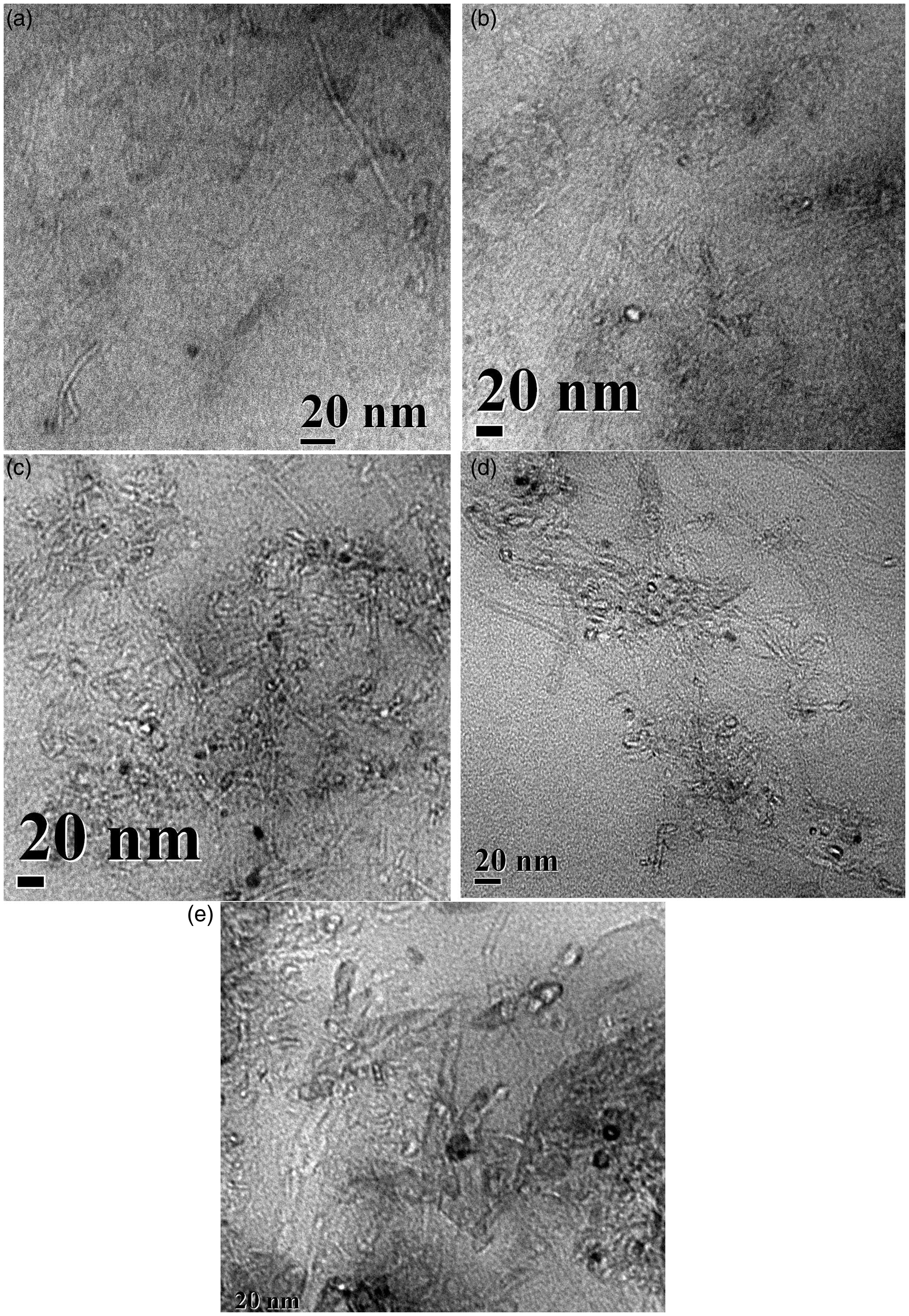
Manufactured sandwich composite samples having MWCNTs in different percentages by weight of epoxy resin are tested in MMB setup for determination of optimum wt% of MWCNT in epoxy resin for enhancement of mixed-mode fracture toughness of the samples. Semi-rigid closed cell PVC foam with a thickness of 30 mm, cell size of approximately 400 µm, density 100 kg/m3 and trade name of Divinycell H100 manufactured by DIAB Inc. is used as the core material in this research work. The PVC foam core is covered with one layer of stitched combination mat followed by a layer of woven roving mat made from glass fibers on both sides. The assembly is placed inside an air tight vacuum bagging system (face sheet and core covered by flow media, porous Teflon sheet and highly permeable breather cloth). The resin system prepared through sonication of resin with MWCNTs and mixing with hardener is then allowed to pass through the preform to cast the sandwich composite panel by vacuum resin infusion (VRI) technology.
The input and output infusion lines are blocked after complete part wetting of the system which is then cured under vacuum for more than 48 h at room temperature (25℃). The process is repeated for manufacturing sandwich panels with different wt% of MWCNTs. Initial delamination in the sample in the form of pre-crack required for the delaminated MMB test is introduced in the samples with the help of 80 µm thick non-stick impermeable Teflon sheet between the face sheet and the PVC core during resin infusion process for sample preparation by VRI method.
Experimental investigation
Figure 2 shows a schematic diagram of the test setup along with sample dimensions. Samples of dimensions 190 mm × 35 mm × 35 mm (where length = 190 mm and width = 35 mm and thickness = 35 mm as per Figure 2) are cut from cured sandwich panels. The initial delamination length is kept as 50 mm. Samples are pasted with aluminum hinge tabs on its both top and bottom face sheets at initially delaminated part using DP 460 adhesive. Distance between the end point of glued part of hinge and that of delamination (a), as shown in Figure 2, is kept at 25 ± 1.5 mm. It should be noted that there exists previous literature [38–42] on sandwich composites without MWCNTs to determine mixed-mode fracture toughness values with similar experimental setup (MMB apparatus).
Schematic diagram of MMB test setup with sample.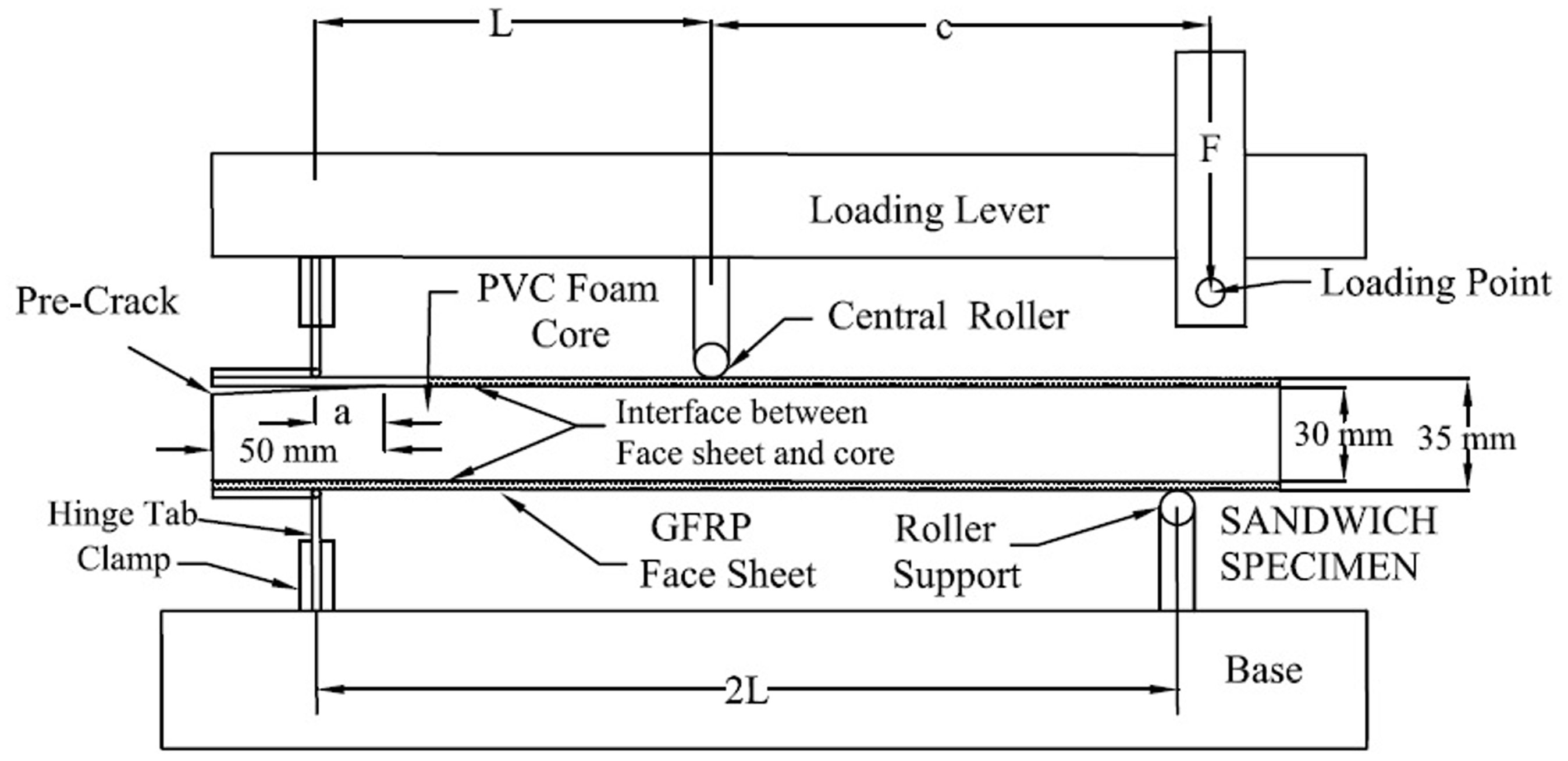
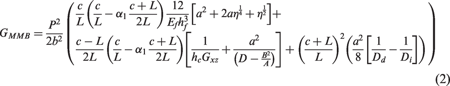
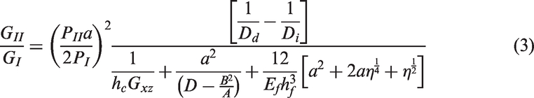
Mixed-mode fracture toughness GMMB of the MMB specimens is calculated using the formula provided by Quispitupa et al. [41]. MMB specimens of sandwich composite panels can be considered as superposition of cracked sandwich beam (CSB) and DCB specimens. Analytic expressions for the MMB compliance and energy release rate for symmetric sandwich specimens (hf1 = hf2 = hf and Ef1 = Ef2 = Ef) have been derived based on load partitioning as

A minimum of lever arm distance is required to avoid contact between crack faces is given by
The condition represented in equation (4) is maintained in all the specimens under MMB tests to maintain the validity of the methodology applied in these experiments.
The aluminum hinge tabs are fitted with the attachments of the lever at top and that of the base at bottom of the steel base of the MMB setup as shown in Figure 3. The lever transfers compressive load to the sample at the upper surface of the top face sheet through a roller attached to the lever. The sandwich beam sample is supported on a clamp and a roller support at bottom which is attached to the base. The whole setup is placed on the loading base of Tinius Olsen make UTM. A C-clamp like attachment and a 10 kN load cell at a loading rate of 0.5 mm/min are then utilized to provide compressive load under different mode ratios on the lever through the wheels attached to the lever as shown in Figure 3. Samples are continuously loaded for propagation of crack by at least 20 mm from the end point of delamination or the point of crack initiation.
Initially loaded MMB sample in UTM: (a) initial and (b) zoomed in region.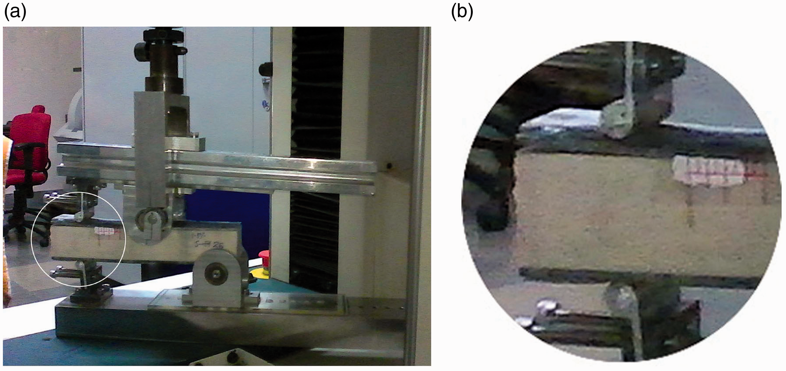
The results of the MMB tests are recorded as per recommendation of ASTM standard D6671/D6671M-13 [40] supported by visual observations. However, it should be noted in here that the case for this experiment is different from determination of mixed-mode fracture toughness in ASTM D6671/D6671M-13 [40]. In this experiment, the initial delamination present in the sample is oriented towards one end of the cross-section in between two dissimilar layers of face sheet and core, whereas ASTM D6671/D6671M-13 prescribes a non-adhesive insert serving as delamination initiator at the mid plane between two laminated layers of similar material properties and geometrical sections. The mean of the results of investigations on at least 10 samples (yielding the results between mean ±two times the standard deviation) is considered for any conclusion derived from the experiment. The MMB samples are subjected to an upward directed load at the left end of the debonded face sheet and a downward directed load at the center, thereby subjecting the specimen to both bending and tensile forces through lever action under different mode ratios. The initiation of crack after reaching the end point of delamination and crack propagation at the face/core interlayer occurs slowly with increase in load. The mean of load readings taken from either side of the sample is taken at the point of initiation of the crack and at other discrete points at each 2.5 mm distance from the end point of delamination with the help of camera attachments. Deflected shape of the sample after the experiment is shown in Figure 4. Except for the changes in stiffness, load capacity and ductility, between the samples with and without MWCNTs, no other significant difference in behavior is observed between them. The crack kinked into the core at a later stage of crack propagation in a large number of samples which agrees with the findings of a previous study [42] where it is stated that the direction of crack propagation depends upon the fracture toughness values of the associated components, i.e. the fracture toughness of the face sheet, interface and the core. The mixed-mode fracture toughness values calculated from the MMB tests of samples with initial delamination incorporate contribution from both mode I and mode II types of fractures.
Final deflection of the MMB sample.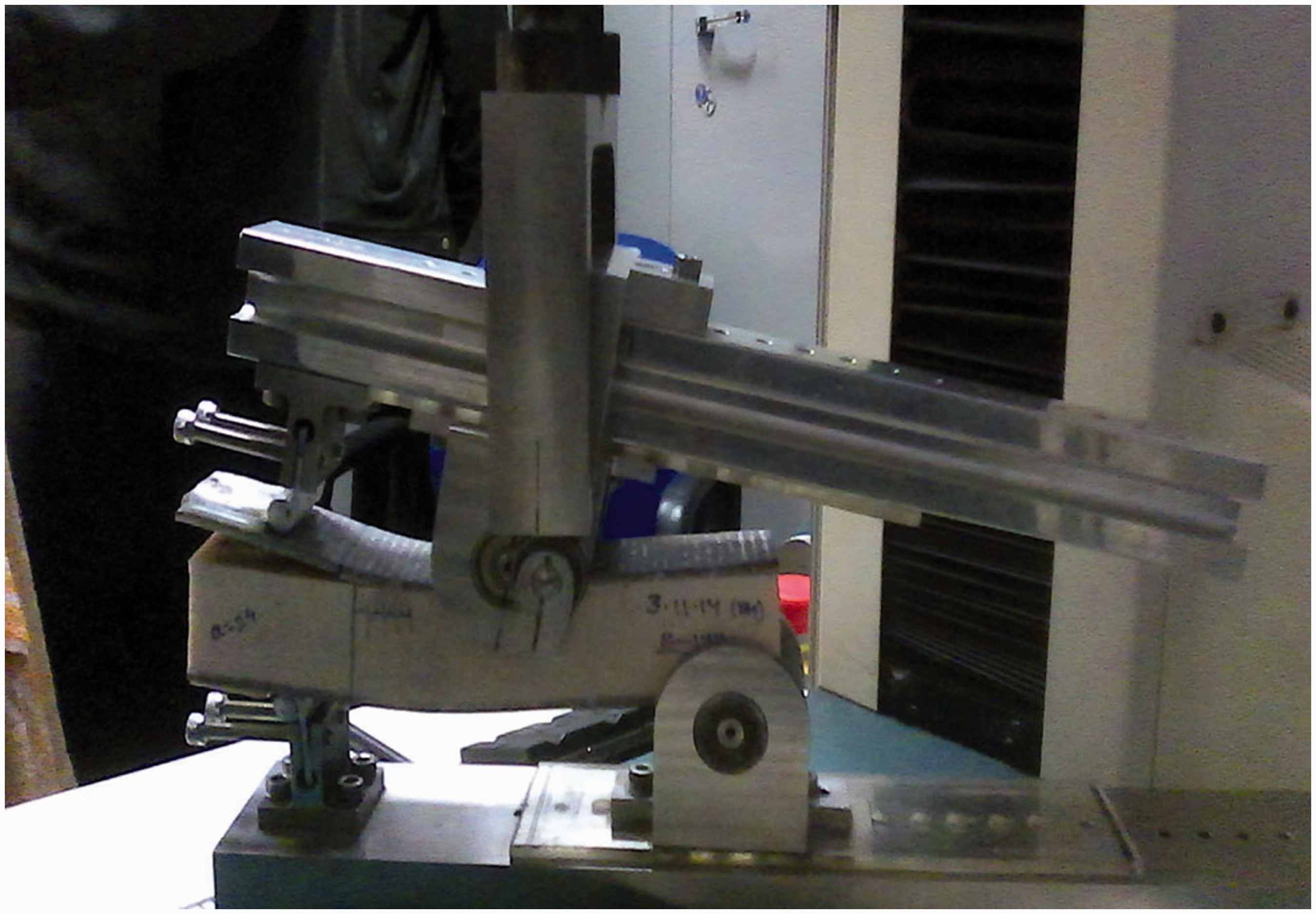
Results and discussions
Experimental investigations have been carried out for specimens with different percentages of MWCNT sonicated resins. But typical plots for load vs. displacements of sandwich specimens with MWCNTs (0.3 wt%) and without CNT are shown in Figure 5. The plot with 0.3 wt% MWCNT has been selected for representation since this percentage provided the best results with regard to performance improvements for mixed-mode fracture.
Load–displacement plot of MMB Samples with different mode ratio: (a) mode ratio 1.0, (b) mode ratio 0.8, (c) mode ratio 0.5.
Increase in peak load-carrying capacity of samples with 0.3 wt% of resin with respect to the sample without CNT.
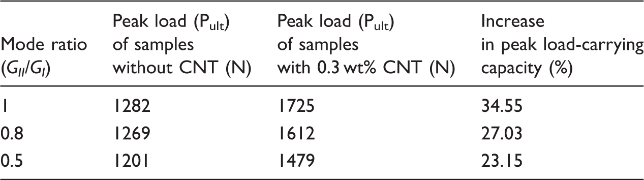
Even without addition of CNT, typically the shear strength is slightly higher than the normal strength. This fact is corroborated by increase in peak strength with increase in mode ratio in Table 1 (mentioned by Quispitupa et al. [42]) for sandwich composites. Since shear resistance offered by the resin mix system in between the glass fiber face sheet and the PVC foam is higher than the mode I resistance to crack, a better regain in strength along with increase in displacement ductility is observed with increase in mode ratio. The random dispersion of MWCNT in the samples is also observed to improve the performance of the samples with increase in mode ratios.
Random dispersion of CNTs in the sample and their modes of failure or pull-out could be observed from destructive tests on tested samples. The samples in which experimentations have been completed are cut into small pieces and then coated with gold palladium alloy using coater machine of Quorum series Q150 RES. These coated samples are observed under a Carl Zeiss MERLIN machine at extra high tension voltage of 5 kV for FESEM studies. Figure 6(a) shows random dispersion of MWCNT within the resin mix at the interface observed at 25 k magnification. Figure 6(b) shows small white circular patches which are practically torn fiber ends, observed at 150 k magnification. Figure 6(c) shows MWCNT bridging the resin system and glass fiber at 200 k magnification. Figure 6(d) shows bridging of MWCNT between two resin blocks individually attached to GFRP and foam respectively at 115 k magnification. Better mechanical interlocking mechanism developed by the MWCNT between the glass fibers, matrix and PVC core results in increase in resistance to mixed-mode fracture in MMB samples in comparison to the samples without MWCNTs.
Micrographs of CNT dispersed in the resin system at the interface of sandwich composite: (a) CNT dispersed in resin system at interface region at 25 k magnification (b) numerous CNT pull-out zoomed in 150 k magnification, (c) Zoomed in CNT bridging and at 200 k magnification and (d) CNT bridging crack at 115 k magnification.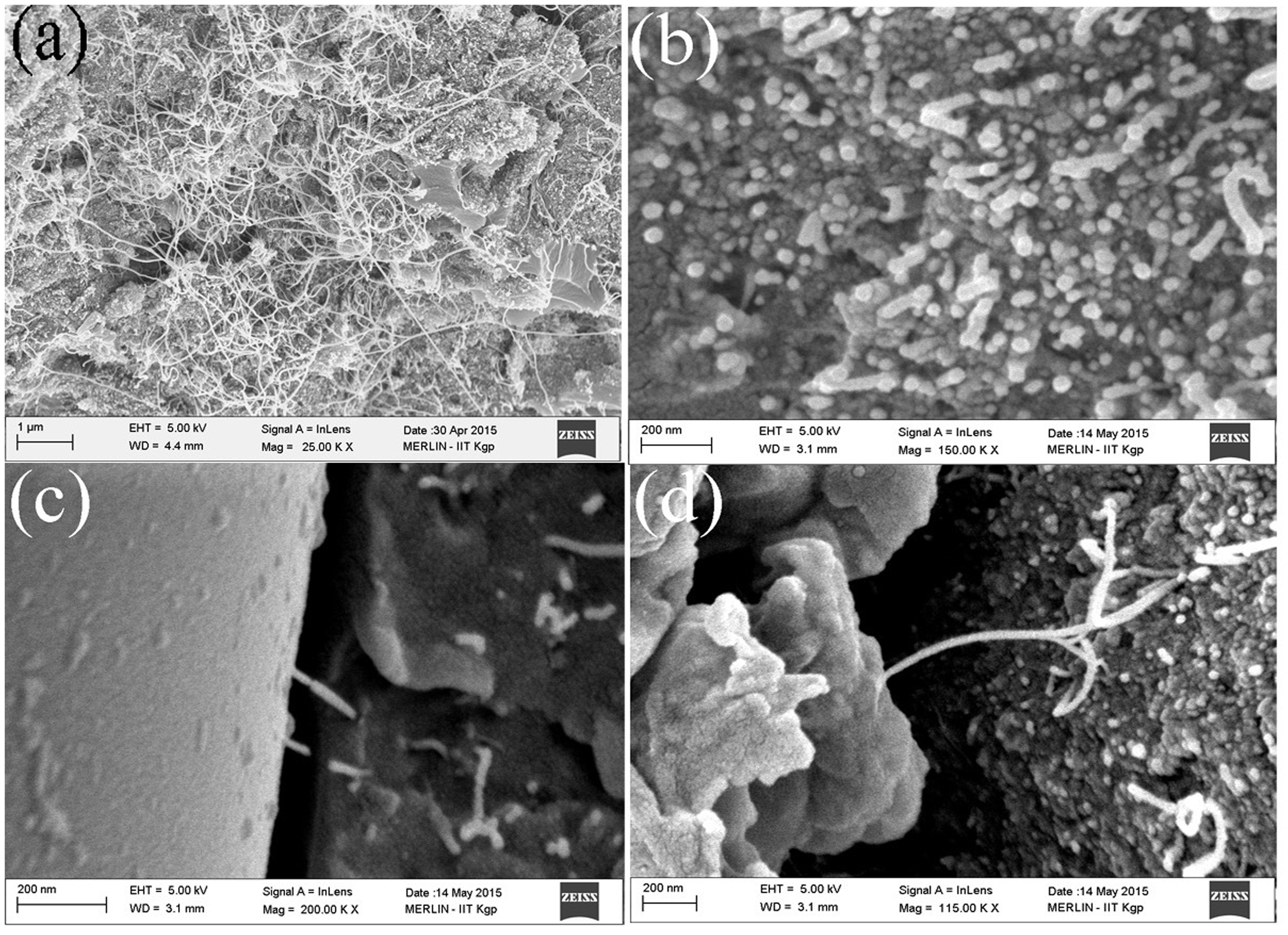
Figure 7 shows that for all % by weight additions of MWCNT (to the sample), the improvement in performance (in comparison to neat samples) increases till 0.3% after which it decreases. This trend of the plots demonstrates that the optimum percentage of MWCNT addition to G/E–PVC sandwich containing the specific type of resin system is 0.3 wt%. Figure 7 also shows error bars in experimental observations. It can also be observed from the figures that values of the maximum fracture toughness at 0.3 wt% MWCNT decreases with reduction in mode II components (or decrease in mixed-mode ratio values) which has also been previously demonstrated by Quispitupa et al. [42]. Primarily the reason for decrease in performance with increased wt% of CNT (> 0.3 wt%) is due to agglomeration effect which subsequently leads to localized stress concentration and zones of crack initiation. The figure also shows that over a wide range of mode ratios selected for this work, 0.3% gives the best percentage gain uniformly. However, it should be kept in mind that this 0.3% which gives the best gain in performance typically depends on the constituents of the sandwich construction as well as the epoxy resin system used in this process. It should be highlighted at this point that authors have reported an improvement of 34.34% in interface fracture toughness value of sandwich composite sample using MWCNT for predominantly mode I loading [24] with 1.5 wt.% addition of MWCNT. This significant difference in percentages of MWCNT (with that reported in this manuscript) is primarily because of the resin system used for the two works and also on type of loading applied. Moreover, the current article focuses on MMB showing different mode ratios of fracture, whereas the previous document focused on double cantilever beam experiments demonstrating primarily mode I behavior. This behavioral trend in results as observed in this manuscript (as well as the previous one [24]) with the addition of MWCNTs has also been previously demonstrated by Fiedler et al. [27] and Zhou el al. [28] for mode I stress intensity factor (KIC) of carbon/epoxy composites mixed with MWCNT. Wichmann et al. [32] also reported 0.3 wt% as the upper limit of CNTs mixed in the resin for maximum percentage gain in nano-reinforced laminated composites with VARTM.
Variation of mixed-mode fracture toughness of MMB sample with percentage of CNT sonication: (a) mode ratio 1.0, (b) mode ratio 0.8, (c) mode ratio 0.5 and (d) superposed plots for different mode ratios.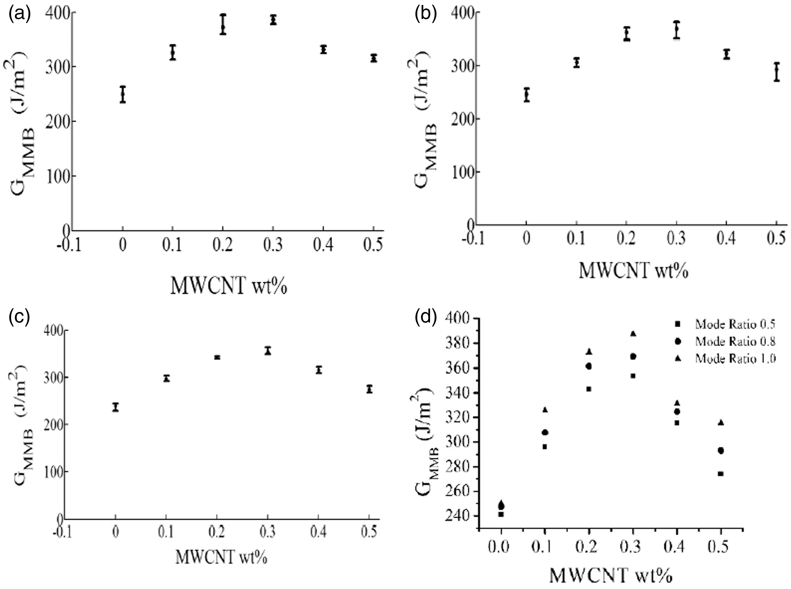
Figure 8 shows increment in mixed-mode fracture energy (GMMB) with different mode ratios for different wt% of MWCNT specimen. Figure demonstrates that the increase in GMMB values is highest for 0.3 wt% MWCNT, and least for 0.5 wt% of MWCNT. The justification of above fact can be sought from HRTEM and FESEM analyses. The larger volume of cylindrical resin system around MWCNTs provides reinforcement effect against pull-out mechanism [43]. Obviously, better dispersion of MWCNT within the resin system leads to better mechanical performance against interfacial delamination. It should also be noted that there is an optimum quantity and addition of MWCNT above the optimum quantity results in agglomeration and thereby do not lead to better performance.
Increment in mixed-mode fracture energy (GMMB) with mode ratio for different wt% of MWCNT specimen.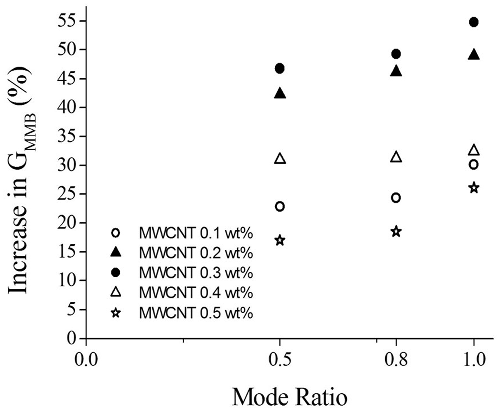
Conclusions
The manuscript highlights the differences in experimentally observed response of interface fracture toughness of samples with and without MWCNT. Out of the different process of addition of MWCNT in composites (as can be obtained from literature), a simple method of sonicating the MWCNT in epoxy resin has been chosen in this research for the PVC-core/glass-fiber/epoxy-resin sandwich to demonstrate significant improvement in mechanical performance of samples against interfacial delamination subjected to mixed-mode loading condition. The research demonstrates an improvement of 34.55%, 27.03% and 23.15% in peak load-carrying capacity for samples with 0.3 wt% MWCNT (weight % being taken with respect to amount of epoxy resin used for sample fabrication) in comparison to samples without MWCNT for mode ratios 1, 0.8 and 0.5, respectively. Good dispersion of MWCNT is also observed with 0.3 wt% MWCNT addition in comparison to other percentages of addition of MWCNT by weight. Samples with 0.3 wt% MWCNT recorded an increase in fracture toughness values of 54.79%, 49.27% and 46.76% in comparison to samples without for mode ratio 1, 0.8 and 0.5, respectively. HRTEM images and FESEM analyses demonstrate good dispersion and fiber bridging of MWCNT in the epoxy resin system, respectively.
Footnotes
Acknowledgements
The authors acknowledge the contribution of Mr. Subhajit Das in manufacturing of the mixed-mode bending apparatus used in the experiment. The first author would like to thank many students and technicians who had helped him for carrying out the experiments. Any opinions, findings and conclusions or recommendations expressed in this manuscript are those of the writers and do not necessarily reflect those of the Space Research Organization, India.
Declaration of Conflicting Interests
The author(s) declared no potential conflicts of interest with respect to the research, authorship, and/or publication of this article.
Funding
The author(s) disclosed receipt of the following financial support for the research, authorship, and/or publication of this article: This work is supported by Indian Space Research Organization, India under Award No. IIT/KCSTC/Chair./New:Appr./13-14/70.