
Abstract
In this paper, a new cost-effective composite bridge deck consisting of multiple steel box cells, concrete slab, and glass fiber-reinforced polymer layer is investigated. First, the structural performance of the deck under static loading is evaluated experimentally. Then the results are validated by a finite element program. Results of the numerical analysis are in good agreement with those of the experiments. The load–displacement relationship, ultimate flexural resistance, failure mode, neutral axis, and strain distribution on glass fiber-reinforced polymer layer and concrete slab are examined during the test. Final results revealed that the ultimate failure of the composite deck initiates by longitudinal cracking on the top surface of the concrete slab. No debonding occurs at the interface between concrete slab and steel boxes which indicates that perfobond ribs could be effectively used for shear connection. The results of experimental and numerical analysis demonstrated that the bridge deck possesses desirable strength and meets the stiffness requirements.
Keywords
Introduction
The bridge deck performs a vital role in a bridge system and its durability affects the whole structural health of the bridge. Several structural defects in bridges are due to the bridge deck geometry and deck condition. Thus, it is essential to design bridge deck systems that have long-term durability and require less maintenance costs [1]. In the early 1980s, exodermic bridge deck that consists of steel profiles and concrete was developed by Neal Bettigole [2]. The ultimate behavior of a steel–concrete composite deck with profiled steel plate and perfobond rib shear connectors was investigated experimentally by Kim and Jeong [3]. Typically, the weight and thickness of the steel–concrete deck are lower than conventional reinforced concrete decks, so they can be used in a longer span, but their resistance against corrosion is low and they have high maintenance costs. A promising solution has been introduced for prevalent problems in steel–concrete decks by development of fiber-reinforced polymer (FRP) composites. The FRP composites have superior material properties such as high specific stiffness, high specific strength, high corrosion resistance, light weight, and excellent durability. In recent years, the interest in using FRP in construction field has been significantly increased worldwide [4].
The FRP advantages in terms of both the chemical and corrosion resistances over conventional construction materials have been identified since the initial development of FRPs following World War II. Their application in chemical process equipment dates back to the early 1950s when the chemical process and industries began using FRPs to replace expensive materials such as alloys and rubber-lined steel [5]. “Durability” is defined as a material’s “ability to resist cracking, oxidation, chemical degradation, delamination, wear, and effects of foreign object damage for a specified period of time, under the appropriate load conditions, under specified environmental conditions.” A review of corrosion resistance and durability of FRP which is used in civil infrastructure is presented in ACI 440R [6]. Cromwell et al. [7] experimentally investigated the behavior of three FRP systems subjected to nine different environmental conditions. They reported that preformed manufactured carbon fiber-reinforced polymer (CFRP) plate carried out very well in all conditions due to their superior quality control and hand laid-up CFRP fabric material generally performed well although the effect of elevated temperature conditioning causes matrix damage leading to increased absorption. Wu and Yan [8] conducted models to investigate the long-term performance of FRP deck structures subject to the both effects of mechanical and environmental loading. Material constituent laws accounting for both strength and stiffness deterioration over time were first developed and then incorporated into the FE analysis. Such constituent relationships were established from experimental data obtained from laboratory accelerated freeze/thaw testing and field performance measurements. Finally, an acceleration factor was proposed which can be able to predict the changes in stiffness and deflection of a monitored FRP bridge deck over a four-year period.
Gan et al. [9] evaluated several cellular glass fiber-reinforced polymer (GFRP) deck panels with different cross-sectional profiles based on finite element analysis. The specimens consist of hexagonal, triangle and rectangular profiles. They reported that panels with 3-cell rectangular section are more suitable in local stiffness and buckling strength than the hexagonal and triangular section panels.
Reising et al. [10] tested four different glass fiber-reinforced polymer decks. They examined whether the composite decks are able to realize many of the expected benefits of using FRP composites. They showed that FRP deck systems could significantly reduce the installation time, and avoid lane closures in comparison to standard reinforced concrete decks.
Zi et al. [11] investigated the behavior of an orthotropic bridge deck made of GFRP and Polyurethane foam, experimentally. The bridge deck was composed of GFRP cells with rectangular holes filled with foam to improve the structural behavior in transverse direction. Results showed that when the GFRP bridge deck is filled with foam; the structural properties in transverse direction such as nominal strength and stiffness are greatly improved. Because of the low density of the foam, the bridge deck is still light enough while the structural properties are improved significantly.
Moon et al. [12] studied the fatigue behavior of the foam-filled GFRP deck. They evaluated the failure mode and stiffness degradation of the tested specimens. They reported that the foam filled in the empty spaces of the modular GFRP bridge deck improved the fatigue behavior and the resisting capacity in the transverse direction. In addition, it is shown that the foam-filled deck with a web spacing of 32 cm has a higher endurance limit and better fatigue behavior than the reference deck.
Brown and Berman [13] investigated the behavior of two glass fiber-reinforced polymer bridge decks and concluded that GFRP deck is a good alternative to the old steel arched deck.
In spite of all these advantages of FRP decks, FRP composites are still too expensive to compete with conventional materials that are used in civil engineering. Therefore, combinations of FRP and conventional materials have recently been studied by a number of researchers to make the best use of materials. The advantages of composite decks include the cost effectiveness and the ability to optimize the cross section based on material properties of each part.
Hillman and Murray [14] proposed the innovative idea of hybrid FRP-concrete decks. They suggested the combination of pultruded FRP sections and concrete to form lightweight deck. FRP section is used as reinforcement and a permanent formwork. Most of the concrete is located above the neutral axis of the hybrid deck. By these considerations, the weight of composite decks is reduced to 50% compared to conventional concrete decks, but it still seemed to be quite expensive.
Bakeri and Sunder [15] conducted numerical studies on composite bridge decks made of simply curved membrane of FRP composites filled with concrete and concluded that the composite deck’s behavior is desirable, especially about the cost.
Saiidi et al. [16] conducted experimental and analytical studies on composite beams consisting of CFRP sections and reinforced concrete slabs. An epoxy resin was used to provide the bond between the concrete and FRP. They concluded that the use of epoxy resin was only partially efficient, and that mechanical connectors or other reliable means are needed to develop composite action between CFRP elements and a concrete slab.
Deskovic et al. [17] proposed that a composite beam consisted of GFRP box section, a layer of concrete in compression zone, and a CFRP laminate in tension zone. Web-fracture, bond failure, and web-buckling were examined. Their study demonstrated feasibility and cost-effectiveness of the composite beam.
Kitane et al. [18] examined flexural performance of hybrid GFRP-concrete beams. In this study [18], three trapezoidal boxes of GFRP laminates were assembled together and a layer of concrete was cast in the compression zone of sections. Their new design reduced the initial costs and increased the stiffness of GFRP composite deck.
Keller et al. [19] tested composite beams consisting of a GFRP plate with T-up stands in tensile, lightweight concrete (LC) as a core, and thin layer of ultra-high strength fiber-reinforced concrete for the compression zone. The ultimate loads of the beams increased due to bonding. However, the failure mode of the beam changed from ductile to brittle.
Sutter et al. [20] conducted experimental and analytical studies on composite beams consisting of a U-shaped section and hollow core elements made of fire safe high performance textile reinforced cement composites (HPTRCC) material. They used ultra-high performance concrete and CFRP at upper and lower sides of the hollow element, respectively. They concluded that their composite beam possesses the same stiffness as the traditional reinforced concrete beams, greater bearing capacity, and lower weight.
Idris et al. [21] examined flexural performance of hybrid beams. In their design, the inner steel tube was placed inside the outer FRP tube and the hollow space was filled with concrete. Aramid fibers were used to manufacture the outer FRP tube in all the specimens. Test results showed that the flexural behavior of the beam was affected significantly due to variation of the diameter and thickness of the inner steel tube. Also, increasing the concrete strength increases the flexural capacity of the beam without influencing their ductility.
Fam and Honickman [22] conducted experimental and analytical studies on new composite girders consisting of a hat-shaped GFRP trapezoidal section, a GFRP plate, a and concrete slab. The concrete slab was optimally designed to be completely in compression. They have presented the flexural performance of the composite beam. The girder with both shear studs and adhesive bonding showed higher strength compared with the girder that was constructed with only the adhesive bond system.
Grimaldi et al. [23] investigated the behavior of slabs which have been made with ordinary and fiber-reinforced concrete, subjected to localized loads and characterized by punching shear or shear failures. The test results have shown that the worst condition is related to the force which is applied close to the supports that causes shear failure. Actually, the ultimate load is lower than the position when the load is applied in the middle of the slab.
As stated above, the main problems that occur in composite decks are summarized to premature web buckling of hollow FRP sections, brittle behavior, insufficient shear capacity between components, the high initial cost, the high weight of concrete decks, and complicated manufacturing process for practical applications.
In this paper, a new composite deck consisting of GFRP layer, steel core, and concrete slab with perfobond rib shear connectors is proposed which can prevent some of the mentioned problems. The structural performance and feasibility of utilizing the composite deck are examined via experimental evaluation and numerical analysis. The results focus on maximum deflection of the deck, ultimate flexural strength, strain distribution on the surfaces, and failure of the specimen.
Materials and method
Details of the experimental program including description of design, configuration of test specimens, material properties, fabrication, and testing procedures are expressed as follows. In order to obtain the desired stiffness and strength, the proposed composite deck is composed of a GFRP layer under the steel boxes and a concrete slab above the steel core. Cross-sectional dimensions and configuration of the deck are chosen as the structural design variables. The main design parameters are width and depth of the steel box cells, the thickness of GFRP layer, and concrete slab. Geometrical parameters of the cross section were determined based on initial finite element analysis program. Figure 1(a) shows the final selected section of the deck profile and the detail of perfobond rib shear connection is demonstrated in Figure 1(b).
(a) Configuration of proposed composite deck, (b) detail of perfobond rib shear connector (all dimensions are in millimeter).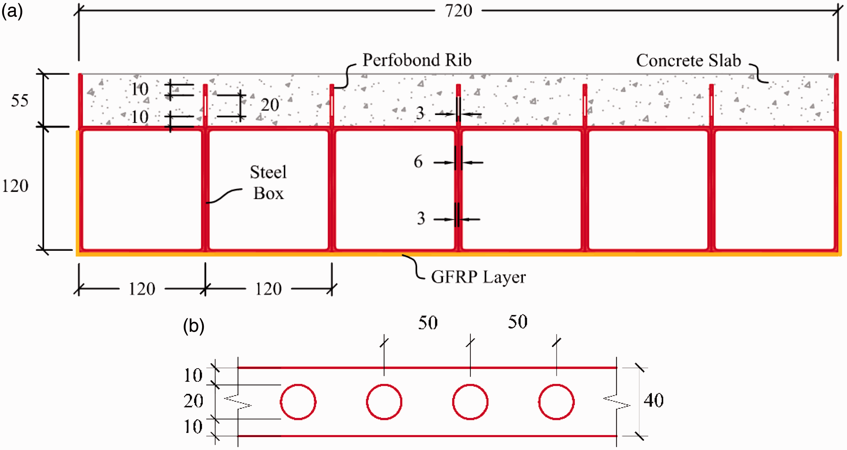
The test specimen which is 1800 mm long, 720 mm wide, and 175 mm deep is simply supported and is tested in positive bending. As shown in Figure 1, the deck consists of six steel boxes with dimensions of 120 × 120 × 3 mm, a GFRP layer, perfobond rib shear connectors, and concrete slab with height of 55 mm which is optimally designated to be completely in compression.
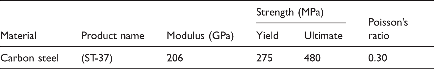
Mechanical properties of steel boxes.
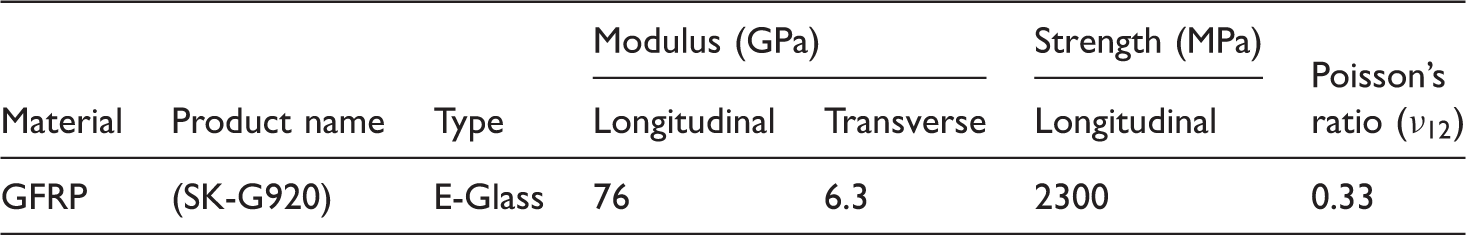
Mechanical properties of glass fibers.
The roles of the epoxy resin are used to glue the GFRP layer on the steel surface and transmit the stresses uniformly over the fibers. The epoxy resin and the hardener are mixed at a volume ratio of 1:0.58.
In order to cast the concrete slab, type II Portland cement was used and the maximum aggregate size is chosen as 12.5 mm. The Young’s modulus and compressive strength of concrete at the time of testing the specimen were evaluated as 33.10 GPa and 48.93 MPa, respectively.
Studies by other researchers [1] show that the longitudinal shear resistance of perfobond ribs is mainly influenced by holes diameter, spacing, and concrete strength. The commonly used diameter of hole is about half of the height of perfobond ribs. The spacing of holes that produces the maximum shear resistance ranges from 2D to 2.5D, where D is the diameter of the hole. In this study, as shown in Figure 1, the diameter and center-to-center spacing of holes for the perfobond rib are chosen as 20 mm and 50 mm, respectively.
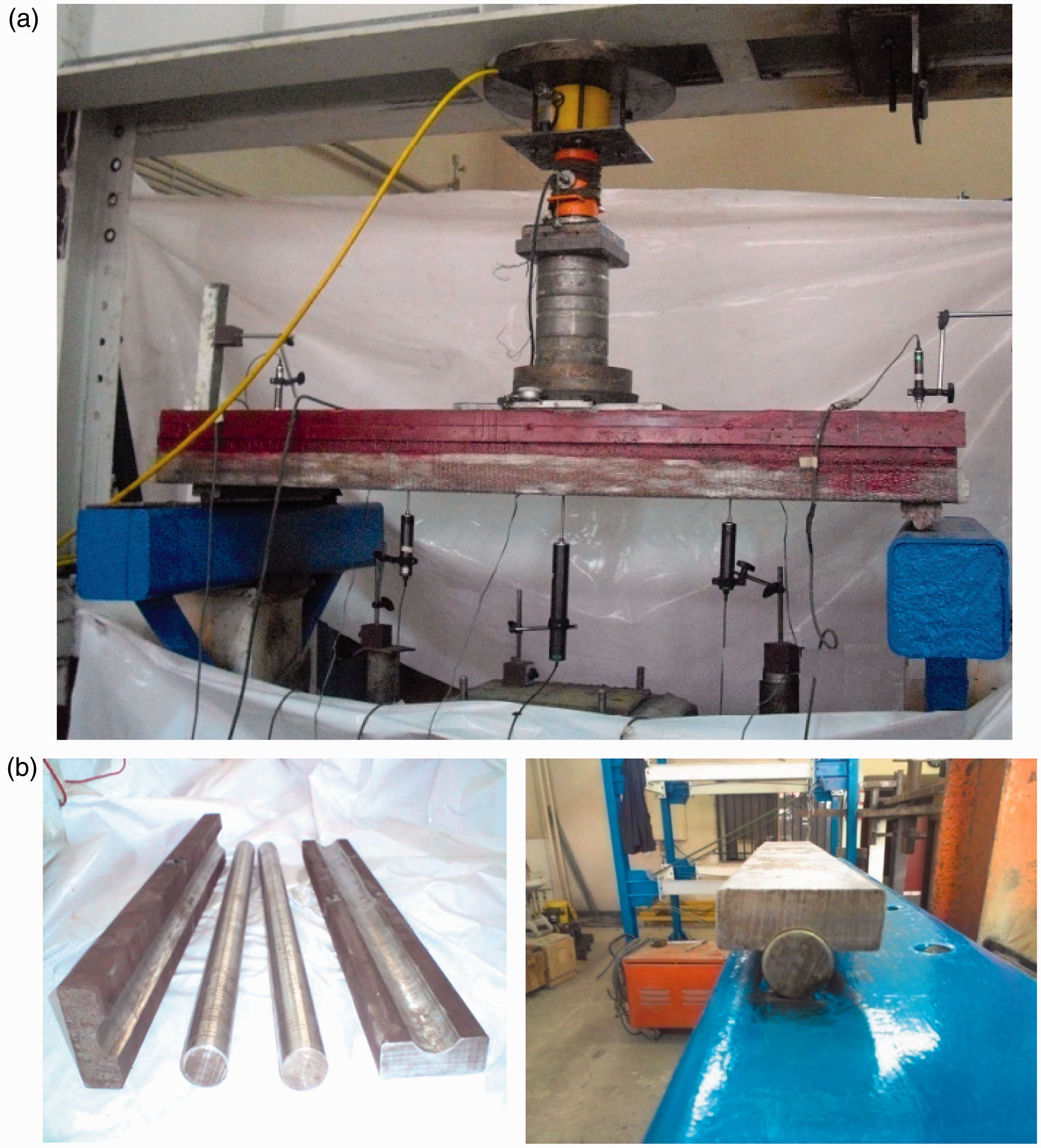
In order to construct the test specimen, six steel boxes were cut to size and welded together throughout their whole length (Figure 2(a)). This overall welding causes the tubes to perform continuously along transverse direction, and obviously is able to transfer the tensile forces in transverse bending.
Fabrication of test specimen: (a) steel boxes welded together; (b) perfobond ribs welded on top of the boxes; (c) vibrating the concrete and (d) GFRP layer adhered to the boxes.
As shown in Figure 2(b), the perfobond ribs are welded on the top flanges of the steel boxes and rust on steel surfaces is removed by a grinder. Then the concrete cast on top of steel boxes was compacted with a vibrator. The specimen is moist cured for 28 days (Figure 2(c)). Then bottom flanges of steel boxes were cleaned using a paint brush and then a layer of epoxy adhesive is applied directly to the bottom surfaces of steel boxes. Just after that, GFRP layer is adhered to the bottom flanges and side faces of steel boxes (Figure 2(d)). Since the steel tubes are surrounded by the FRP layer, corrosion resistance is provided for the outside part of the tubes. Also to provide the corrosion resistance of the inner part of the tubes, they could be filled with polyurethane foam in field applications, as it was used in Zi et al. [11].
The specimen is tested in three-point bending with an effective span of 1650 mm as shown in Figure 3. A displacement–control procedure is adopted with a displacement rate of 1 mm/min. The load is applied at the midspan through a 508 × 254 × 20 mm steel plate to represent a HS 20 truck dual-tire wheel loading (AASHTO LRFD 2010) [24]. A rubber pad, with the same length and width as the steel plate, was used to distribute the load more uniformly. The thickness and the elasticity modulus of the rubber pad are taken as 8 mm and 100 MPa, respectively. It was placed between the deck and the steel plate.
Loading scheme of test specimen.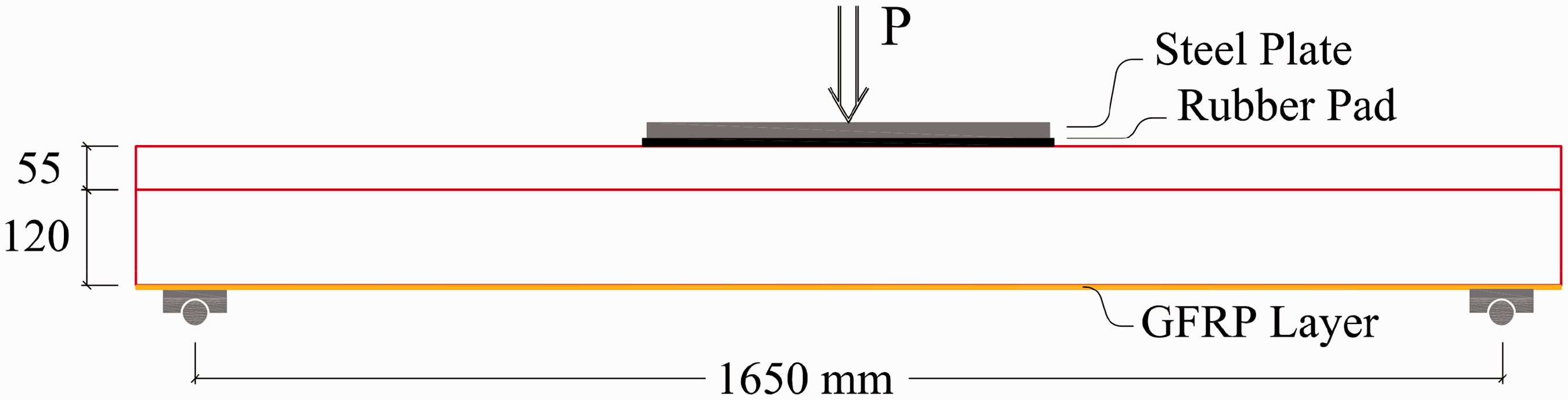
The test specimen is instrumented with both strain gauges and displacement transducers. The strains are measured using strain gauges at the top surface of the specimen. They are installed on points T1, T2, and T3 on the concrete slab as shown in Figure 4(a) and at the bottom face of the specimen on points B1, B2, B3 and B4 on the GFRP layer as shown in Figure 4(b). The strain gauge B4 is placed under T2, and therefore their strains can yield the situation of the neutral axis. Results of the other strain gauges are used to verify and to adopt the numerical model in finite element program. The vertical deflections of the specimen are measured using linear variable deflection transducers (LVDTs) at three points D1, D2, and D3 as illustrated in Figure 4(b). The complete experimental setup and instrumentation are shown in Figure 5(a), and Figure 5(b) shows steel supports of the deck. As shown in Figure 5, the specimen is simply supported on rollers made up by two parts; a 540 × 80 × 30 mm steel strip having a groove, and a bar with diameter of 35 mm. When these two pieces are assembled on each other and lubricated, the supports at two ends of the deck behave like idealized simple supports.
(a) Locations of strain gauges at top. (b) Locations of LVDTs and strain gauges at bottom (all dimensions are in millimeter). (a) Test setups and instrumentation. (b) Steel supports.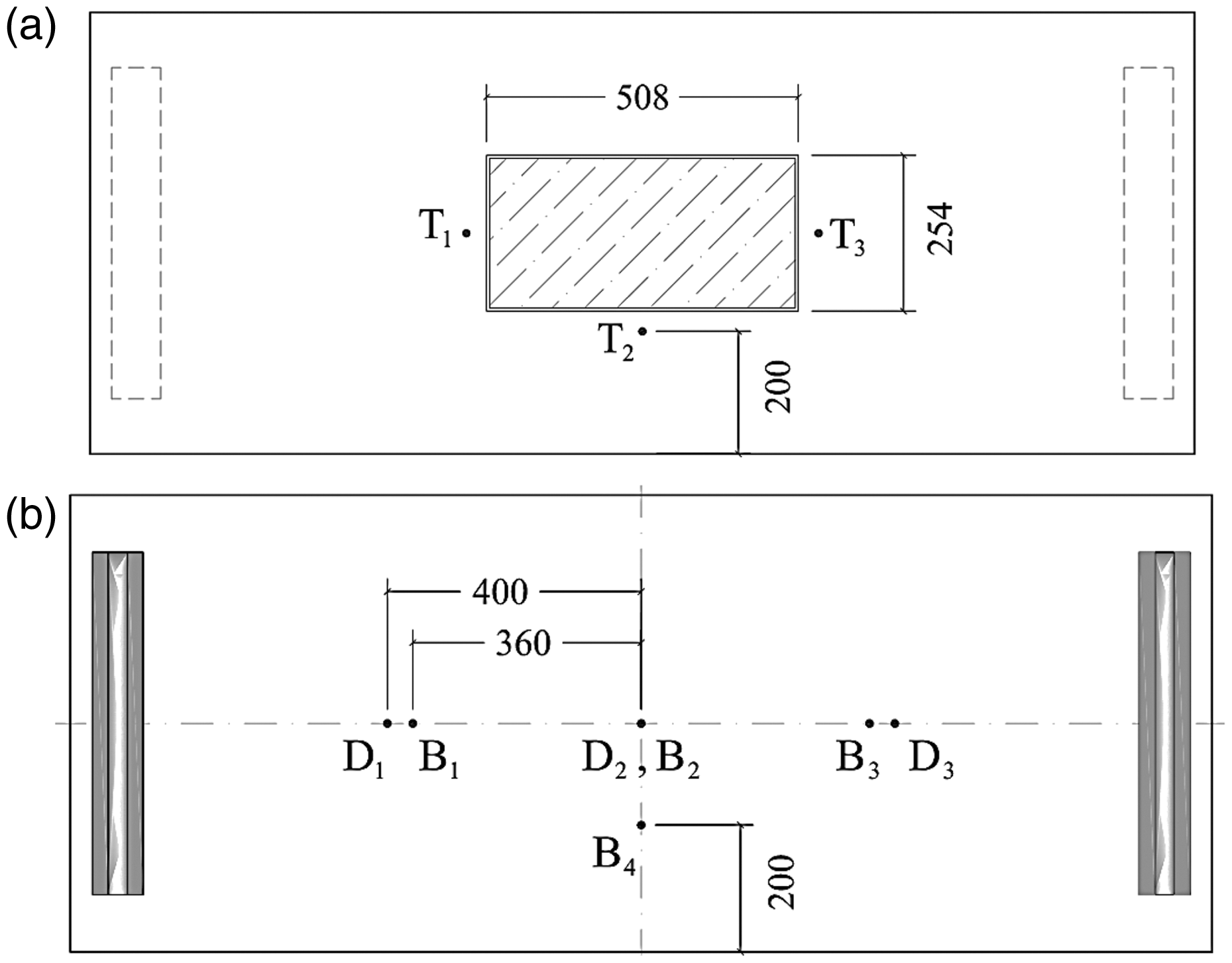
Experimental results and discussion
It is recommended in AASHTO LRFD [24] bridge design specifications that the maximum deflection under live loads should be smaller than L/800, where L is the center-to-center distance between girders in the transverse direction of the truck. The live load for this case is
Since the length of the span the test specimen is 1.65 m, the maximum deflection under service load should be smaller than
The load–displacement response at the midspan of the specimen and also the finite-element (FE) prediction (as discussed later) are shown in Figure 6(a). Maximum load and displacement are evaluated as 1080 kN and 25.17 mm, respectively. In order to clarify the effect of using the FRP layer in the performance of the model, a numerical specimen without GFRP layer is modeled by ABAQUS and the results are shown in Figure 6(a) and could be compared with the model comprising FRP layer. Since the FRP has linear behavior till its ultimate stress, which is much higher than the steel yielding stress, the strength of the model containing the FRP layer is increased even after the steel yielded. The ultimate load capacity of the specimen without FRP layer is about 870 kN, which is augmented to about 1080 kN in the case of adding a FRP layer in the bottom of the deck. So the load capacity of the deck is increased by about 24% by adding the FRP layer. Therefore, besides its anti-corrosion properties, the GFRP layer improves the structural behavior of the deck significantly.
Load–displacement response at points (a) D2 (midspan) and (b) D1.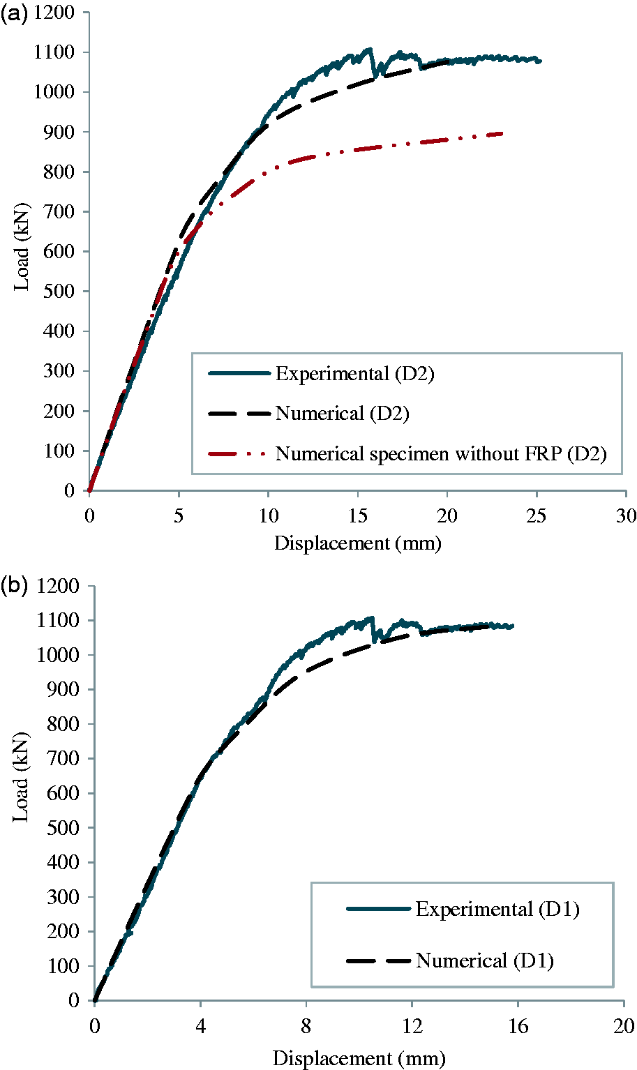
Figure 6(b) shows the load–displacement curves for the displacement measured at point D1. As the load increased, the concrete slab began to crack.The sound of cracking of the concrete is heard during the flexural test. Longitudinal cracks occur at the top of the concrete slab along the perfobond ribs as illustrated in Figure 7 and the cracks propagate progressively until the failure occurred. The failure of experimental specimen is caused by concrete slab crushing.
Failure modes of composite deck. (a to c) Longitudinal cracking at concrete slab; (d to f) concrete crushing at both sides of loading plate.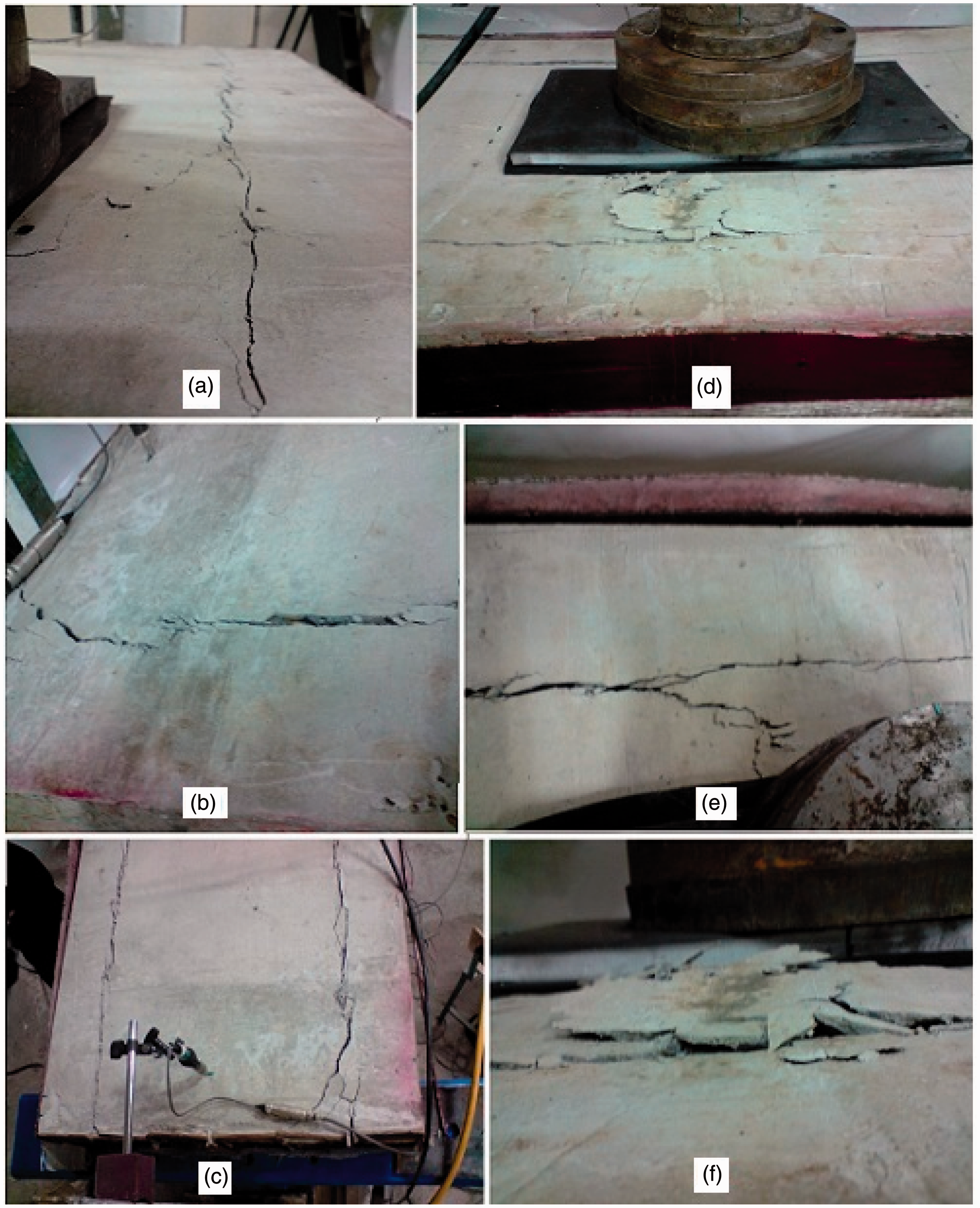
The perfobond ribs shear connectors prevent any slippage, and therefore, no debonding occurred at the interface between concrete slab and steel boxes.
As stated above, the mode of failure is not local punching failure mode or other local damages which are common in cellular all-FRP panels [25], but it is caused by concrete crushing as shown in Figure 7. Therefore, it could be stated that the concrete slab has reached its full capacity in flexural strength. It is discovered from the strain gauge data and the load–displacement curve (Figure 6) that the steel tube just yielded in some areas but is still far from its final failure, so the deck has sufficient deformability to be safe enough on practical uses in the field. Conversely, most of all-FRP decks have linear load–deflection response till failure which usually occurs suddenly [18,19,26–29]. Also, visual inspection after the test revealed no rupture in the GFRP layer.
The load–strain curves for the strain measured at point B2 is shown in Figure 8. It shows that the maximum longitudinal tensile strains in the GFRP layer at failure load are lower than the ultimate tensile failure strain. Needless to say that the kink in the curve of Figure 8 is due to the yielding of the steel.
Load–longitudinal strains response at midspan of specimen (B2).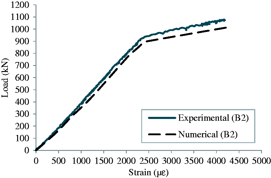
Based on measured strains from gauges T2 and B4, the location of the neutral axis can be evaluated. In the beginning of the loading, as shown in Figure 9, the strain profiles are observed to be nearly linear passing through zero strain at a height of approximately 100 mm from the bottom of the specimen, representing the position of the neutral axis. By increasing the applied load, this height is decreased gradually as far as the height of the neutral axis alters to 95 mm from the bottom. It is due to concrete cracks and fractures which decrease the effective stiffness of the slab. So by focusing on the location of neutral axis, it is observed that whole thickness of the concrete is placed in the compression zone during the positive bending.
Strain variation of specimen in the depth direction based on linear interpolation (T2 and B4 gauges).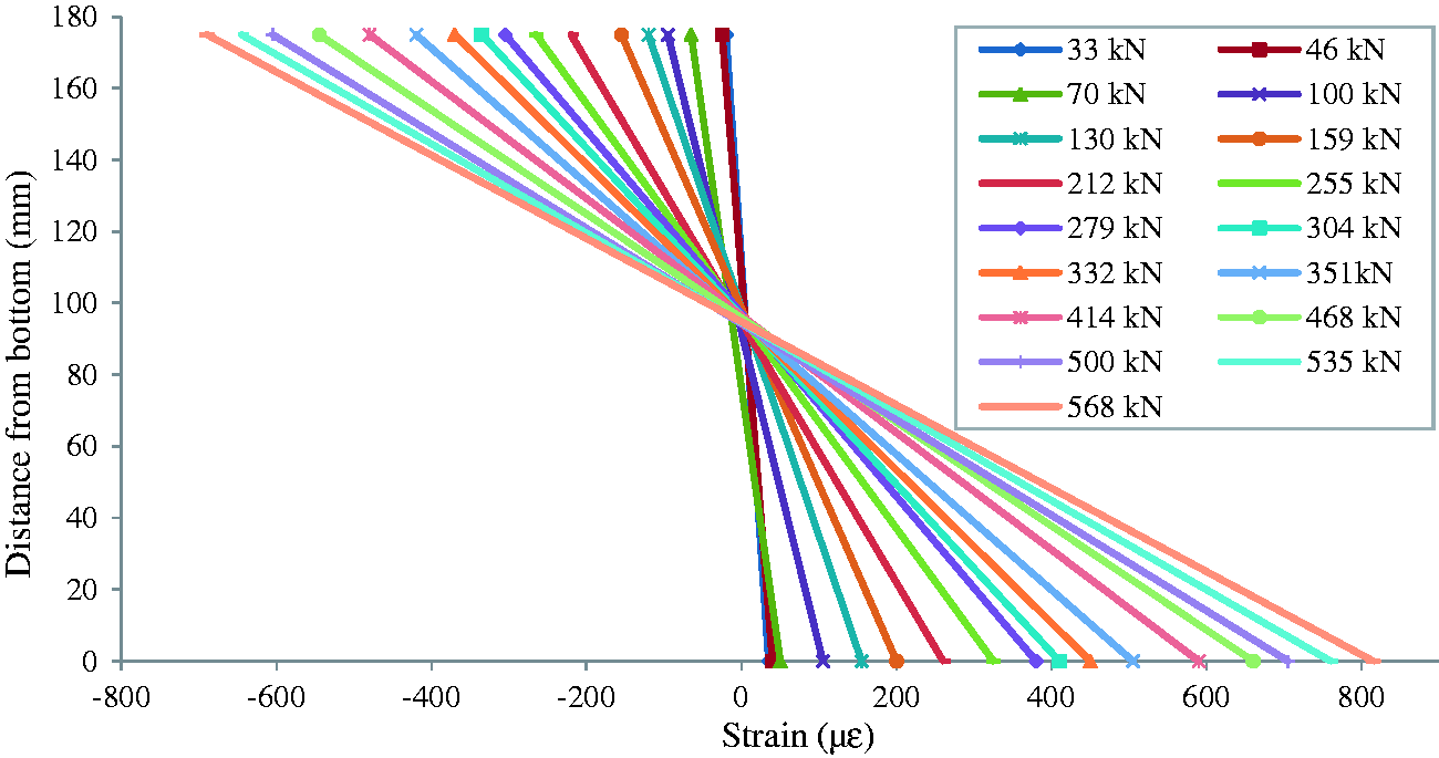
In optimized designing procedure of the composite decks, the concrete is recommended to be completely in the compression zone and not in tension. In this research, this is made by employing hollow steel tube boxes and thus no concrete is used in tension zone. This technique will significantly decrease the weight of the deck.
The weight of the deck is 230
Finite element analysis
A three-dimensional finite element analysis is also carried out to evaluate the flexural behavior of the proposed composite deck. The numerical analysis is performed by finite element softwareABAQUS [30]. The procedure is summarized as follows.
The concrete damaged plasticity model is adopted to model the concrete slab. This model is based on the assumption of isotropic damage and is designed for applications in which the concrete is subjected to arbitrary loading conditions, and containing cyclic loading. The model considers the reduction of the elastic stiffness caused by plastic straining both in tension and compression [30]. It supposes that the main two failures are tensile cracking and compressive crushing of the concrete material. The progression of the yield (or failure) surface is controlled by two hardening variables, Response of concrete to uniaxial loading in (a) tension and (b) compression [30].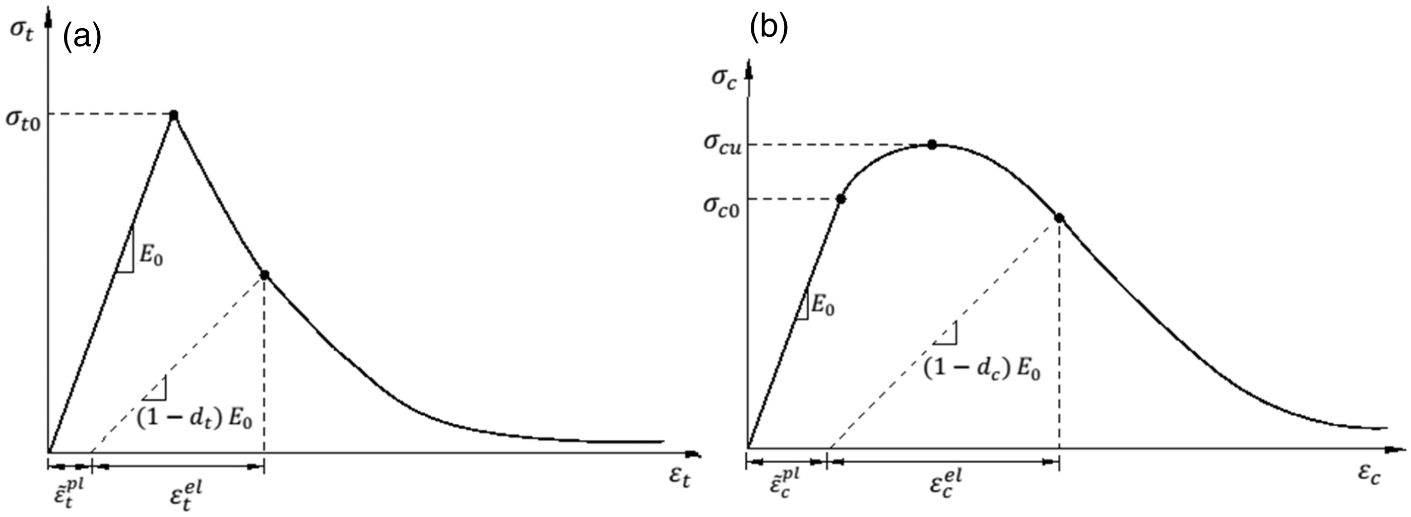
The stress–strain response of concrete in compression is defined according to Mander et al. [31] and the tension stiffening response is defined in terms of tensile stress and axial deformation according to Reinhardt et al. [32]. The GFRP layer is also modeled as orthotropic elastic material and the plasticity of steel is defined by a nonlinear isotropic hardening model.
For the FE analysis of the test specimen in this study, all material properties are chosen as described previously. Solid elements are used to model the concrete slab, steel boxes, rubber pad, and the steel loading plate. This element includes eight nodes and three translational degrees of freedom at each node. The GFRP layer is modeled using shell elements. This element consists of four nodes and six degrees of freedom per node, three translational and three rotational.
The finite element model of composite deck is shown in Figure 11. In order to make computational time minimum and simultaneously achieve the highest accuracy, based on comprehensive mesh convergence studies, mesh size is adopted with a maximum element size of 60 mm as shown in Figure 11. Boundary conditions are applied to simulate a simply supported condition by modeling the rollers exactly as they were used in experiment. Similarly, in order to simulate all experimental conditions more accurately, the rubber pad and the loading patch are modeled just as experimental specimens. Nonlinear iterations are solved using Newton–Raphson method.
Finite element model of composite deck.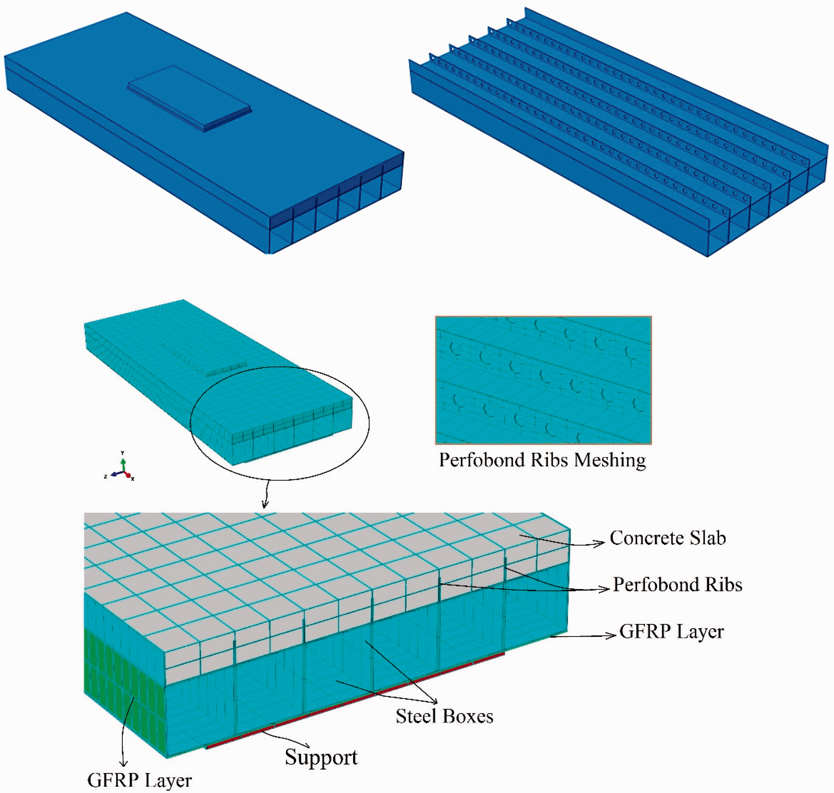
Results of finite element analyses
Figure 6(a) shows the load–displacement responses at midspan of composite deck in experimental and numerical cases. The results are in good agreement on both ultimate strength and stiffness viewpoints. As shown in displacements contours in Figure 12(a), the maximum displacement of the numerical model is about 23.8 mm, which is about 5% lower than that of the experimental case and indicates a close agreement.
(a) Displacement contour and (b) principal plastic strain of composite deck.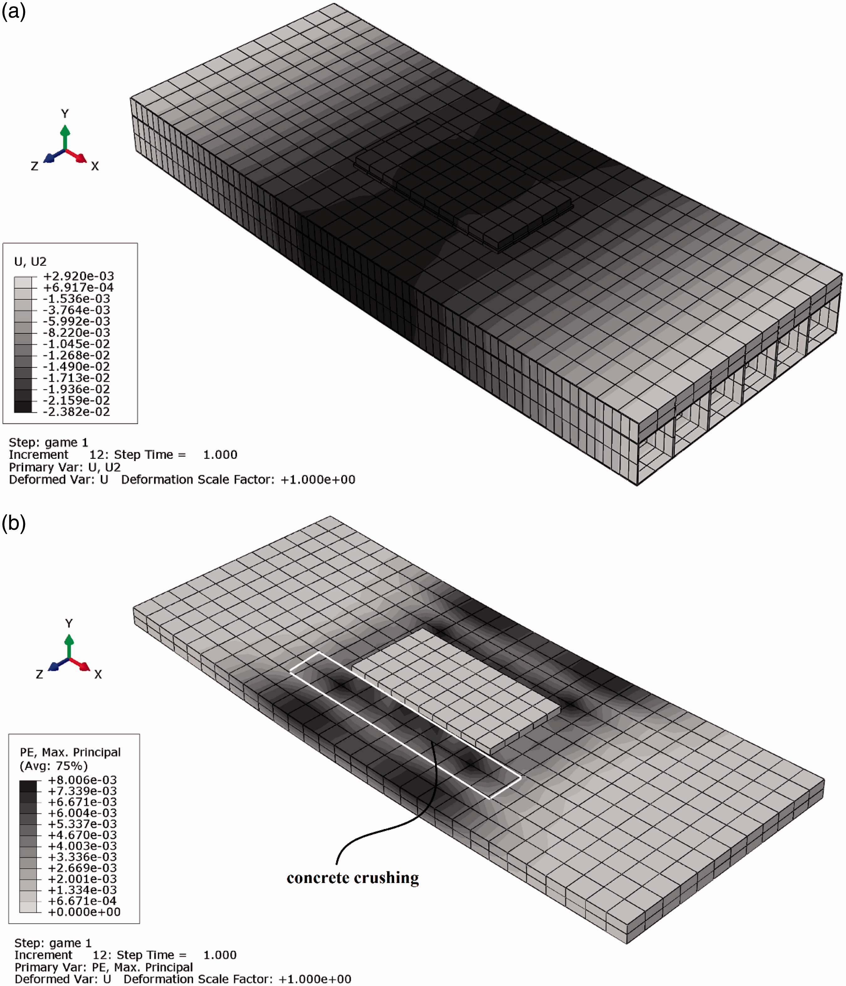
In Figure 12, lines of deflection contour are almost straight in the transverse direction and are parallel. It demonstrates that the deck has sufficient traverse stiffness; otherwise, the contours would be elliptical.
Comparison between experimental and numerical strains at T1.
Comparison between experimental and numerical strains at T2.
As shown in Figure 7, the failure of experimental specimen is caused by concrete crushing and longitudinal cracking at the top of the concrete slab along the perfobond ribs shear connectors. In addition, Figure 12(b) shows the plastic strain and the principal plastic strain is the best criterion for studying tension (cracking) and compression (crushing) failure in numerical modeling of concrete.
Figure 12(b) shows the position in which the concrete is crushed in the numerical specimen. The location of concrete crushing (both sides of loading plate) and longitudinal cracking at concrete slab are compatible in the experimental result (Figure 7) and numerical result (Figure 12(b)).
According to Figure 12(b), the maximum value of plastic strain is rather high and shows the concrete crushing and extensive damage. Generally, the failure of numerical specimen is similar to that of experimental one which is due to concrete crushing exactly in the same positions.
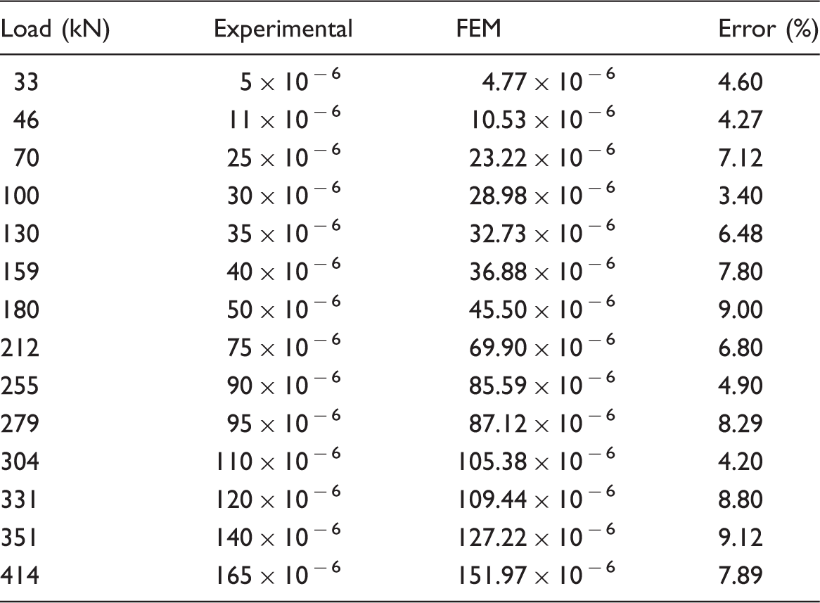
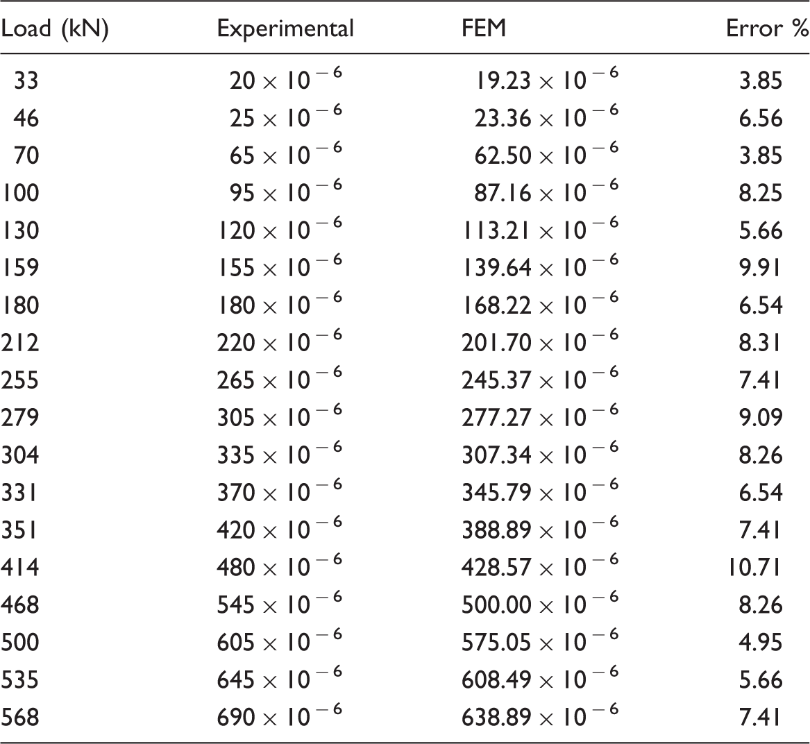
Figures 6 to 8, Figure 12, and Tables 3 and 4 could verify that experimental and numerical results conform to each other quite well in terms of deflections (Figures 6 and 12(a)), ultimate strength (Figure 6(a) and (b)), stiffness (Figure 6(a) and (b)), strains at FRP layer (Figure 8), damages, location of concrete crushing and longitudinal cracking (Figures 7 and 12(b)), and strains at concrete slab (Tables 3 and 4).
Hence, the numerical analyses performed in this research are reliable. Therefore, the behavior of proposed composite deck can be evaluated through numerical methods, without conducting costly experiments.
Summary and concluding remarks
A new economical composite bridge deck consisting of multiple steel box cells, a concrete slab, and a GFRP layer has been introduced. The performance of the proposed composite bridge deck was evaluated using experimental and numerical approaches. Based on the observations and analyses, the following conclusions can be drawn.
Concrete is designed to be always under compression in the longitudinal direction. The concrete is not used in tension, so the weight is significantly decreased compared with common concrete-filled composite decks. GFRP is corrosion-resistant, so the steel is not exposed to environmental conditions; therefore, the system is to some extent resistant to environmental degradation. By employing the GFRP layer, the required thickness of steel is decreased and hence the weight of composite deck is reduced. The implementation of perfobond rib shear connection ensures composite action of concrete slab and steel boxes. The failure mode of the proposed composite deck is favorable due to the yielding of the steel boxes and nonlinear response of the concrete slab. The proposed hybrid bridge deck could be designed to meet the AASHTO live load deflection recommendation. Most parts of proposed deck can be fabricated in the factory; therefore, good quality control can be assured, and the construction period could be shortened by prefabricating the decks. The proposed bridge deck can also be employed in a building as a floor or roof deck. The FE model predicted the flexural behavior and failure modes of composite deck with excellent accuracy compared with the experimental results. Therefore, the deck has this positive feature that its structural behavior could be simulated and predicted by FEM. Briefly, the proposed deck has an extremely high strength, low thickness, low weight, suitable deformability, and capability for prefabrication.
Footnotes
Declaration of Conflicting Interests
The author(s) declared no potential conflicts of interest with respect to the research, authorship, and/or publication of this article.
Funding
The author(s) disclosed receipt of the following financial support for the research, authorship, and/or publication of this article: This research is supported by Mazandaran Road and Urban Department of Iran and the Housing and Urban Development Research Center (grant no. 18672). The research job has been carried out in Babol Noshirvani University of Technology in Iran.