
Abstract
In this paper, the bending stiffness-to-weight-ratio of novel hybrid sandwich structures is investigated. The build-up of the sandwich panels consisted of face sheets made from carbon fibre reinforced polymer, aluminium foam cores and an interface of foamed polyurethane. The sandwich panels were produced in a single step, infiltrating the face sheet fibres and connecting the face sheets to the core simultaneously. By means of mechanical characterization, specimens with several variations of face sheet architecture and thickness, core structure and interface properties were examined. Quasi-static four-point bending and flatwise compression tests of the sandwich composites were conducted, as well as tensile tests of the face sheets. The results of the tensile and compressive tests were integrated in analytical models, describing the sandwich stiffness depending on the load case and the face sheet volume fraction. The effective Young’s modulus of the composite, measured in the four-point bending test, correlates well to the modelled effective bending modulus calculated from the single components face sheet and core. The model underestimates the effective density of the bending specimens. It could be shown that this underestimation results from the polyurethane foam connecting the face sheets to the core, as the mass of this polyurethane is not included in the model.
Keywords
Introduction
For applications requiring a high stiffness-to-weight-ratio, sandwich structures are a suitable solution [1].
As face sheet materials, fibre reinforced plastics (FRP) [2–9], sheet metal of aluminium [10–12] or steel [13], or combinations of metal and FRP [8,14] are commonly used. Carbon fibre reinforced polymers (CFRP) are used if a maximized specific stiffness is desired [8,15].
The core structures are often made from honeycomb [10,11,15,16], polymeric foam [4,5,7,17] or metal foam structures, mostly with closed cells (CC) [8,9,10,12–14], less commonly with open cell (OC) metal foams [18]. In some cases, a light wood is used [19,20]. The core structures can be reinforced by corrugated structures, with [5] or without [6] additional foam enclosure, resulting in isotropic properties of the sandwich. With metal foam structures, as used in this paper, high values of energy absorption during failure can be achieved [10].
The connection of face sheets and core is usually achieved with a thin adhesive film applied to the face sheet [8,12]. When a honeycomb core is applied, the adhesive forms fillets, creating a locally increased connection surface, as investigated by Jen et al. [11]. Sandwiches with CC aluminium foam cores can be produced with integral aluminium sheet metal surfaces from a single semi-finished product, as utilized by Crupi et al. [10,14]. Also diffusion bonding can be used, but is limited to connect a metal core to metal face sheets [13]. With FRP face sheets, production can be realized through resin-transfer-moulding [9] or injection moulding [21]. Colombo et al. [22] avoided the use of adhesive by casting face sheets of textile reinforced concrete onto polystyrene foam cores. However, these processes are limited to CC foams, as OC foams (as well as CC foams with weak cell walls, in case of high-pressure-processes [21]) would be filled with resin and hence lose their lightweight efficiency. Pollien et al. [18] produced sandwich panels with graded OC core structures and aluminium face sheets by infiltrating graded layers of salt powder with molten aluminium. The minimum relative density of the aluminium foam achieved with this process was 15%, whereas commercially available OC aluminium foams reach densities of about 5%. Additionally, the infiltration process used by Pollien et al. either requires an additional processing step for joining the face sheets and the core, or is limited to aluminium face sheets.
For this work, the CFRP face sheets were combined with aluminium foam cores by a polyurethane (PUR)-spraying process, previously described by the authors in [23]. This process combines the infiltration of fibre reinforced face sheets and the joining of face sheets and core in one production step. Foamed PUR acts both as the face sheet matrix and as a lightweight adhesive. Using this process, OC foam structures can be used as sandwich cores without flooding the foam structure with adhesive. Instead, the connection surface of core structure and PUR foam can be controlled by the amount of applied PUR [23]. Therefore, the lightweight potential of CFRP/aluminium-foam sandwiches produced this way is suitably higher. Furthermore, the in-mould-assembly of the sandwiches without a separate joining process is considerably more cost efficient.
Suitable testing procedures for the bending stiffness are quasi-static three-point [7,20,24,25] or four-point [7,8,19,22–26,27] bending tests, as chosen for this work. An advantage of the latter is the constant momentum (and therefore constant tension) in the section between the inner loading bars, allowing the shear modulus to be isolated. Different failure mechanisms, depending on specimen geometry and loading spans, are extensively researched [7,8,22,26,27], but not within the scope of this work, as it focuses on bending stiffness.
Dietrich [3] investigated the bending stiffness of sandwich panels with honeycomb cores and GFRP face sheets using three- and four-point-bending as well as tests of the single components. Considerable deviations from the linear sandwich theory were observed, with overestimated face sheet stiffnesses in the bending tests. The deviations were assumed to be a result of the applied fibre-spraying manufacturing process.
Fang et al. [19] and Srivaro et al. [20] focused on the bending stiffness of sandwich panels with wooden core, combined with wooden [20] and GFRP [19] face sheets, respectively. As Fang et al. used three-point-bending, they obtained the shear modulus from shear tests. Srivaro et al. estimated the shear modulus, as well as the tensile properties of the face sheets. Both research works conclude with the observation that the Timoshenko beam theory fits well to the elastic bending deformation of sandwich specimens.
Fam et al. [5] conducted bending tests on large sandwich panels with GFRP face sheets and PUR foam cores. For the elastic part of the deformation, they also use the Timoshenko beam theory with satisfying compliance. Furthermore, they obtain the component properties from tensile, compression and shear tests of the core, as well as tensile tests of the face sheets.
However, neither of the works in [5,19,20] did investigate the correlation of the elastic properties with the sandwich density, although Fang et al. included the values of a numerical stiffness-to-weight-ratio. Crupi et al. [10] compared the density of their tested sandwich specimens, but concentrated their work on the investigation of indentation.
The goal of the present work was a comparison of the sandwich bending modulus with the stiffness of the single components: face sheets and core. This contribution aims for the investigation of sandwich panels with OC aluminium foam cores and simultaneously joined and cured CFRP face sheets. As known to the authors, such in-mould-assembled CFRP/aluminium-foam sandwiches have not been investigated before. Since both open- and closed-cell foam structures, as well as Nomex honeycomb (NH) structures, were used as sandwich cores, a systematic investigation of mechanical properties based on identical process routes was made possible.
The effective density of face sheets, cores and sandwich panels was included in the investigations. Different variations of the area weight of the face sheet fibres, as well as different cell structures and densities of the core were compared. An estimation of the sandwich bending stiffness was calculated for each variation, depending on the volume fractions of face sheets and core inside the sandwich (compare [1,28]), and based on their experimental results. This model was then compared to the results of a bending test of the sandwich panels.
Materials and methods
Materials
Two different structures of aluminium foam were used as cores in the sandwich panels. The first had an OC structure (see Figure 1(a)) of aluminium AlSi7Mg0,3, with a relative density of approx. 5% and a cell size of approx. 5 mm. It was produced by the company m-pore in Lindenberg, Germany. The second foam had CCs (see Figure 1(b)), a relative density of approx. 8% and a cell size of approx. 5 to 8 mm. This foam, label-named ‘Alcoras’, was supplied by the company AlCarbon from Bremen, Germany. As a reference to the work by Dietrich [2,3], a NH structure with phenolic coating was used, see Figure 1(c). It was produced by the company Euro-Composites, Echternach, Luxembourg, label-named ‘ECA 9.6-48’. All core panels have a thickness of 20 mm.
Core structures used in sandwich specimens. (a) OC structure by m-pore, (b) CC structure ‘Alcoras’ and (c) NH structure ‘ECA 9.6-48’. OC: open cell; CC: closed cell; NH: Nomex honeycomb.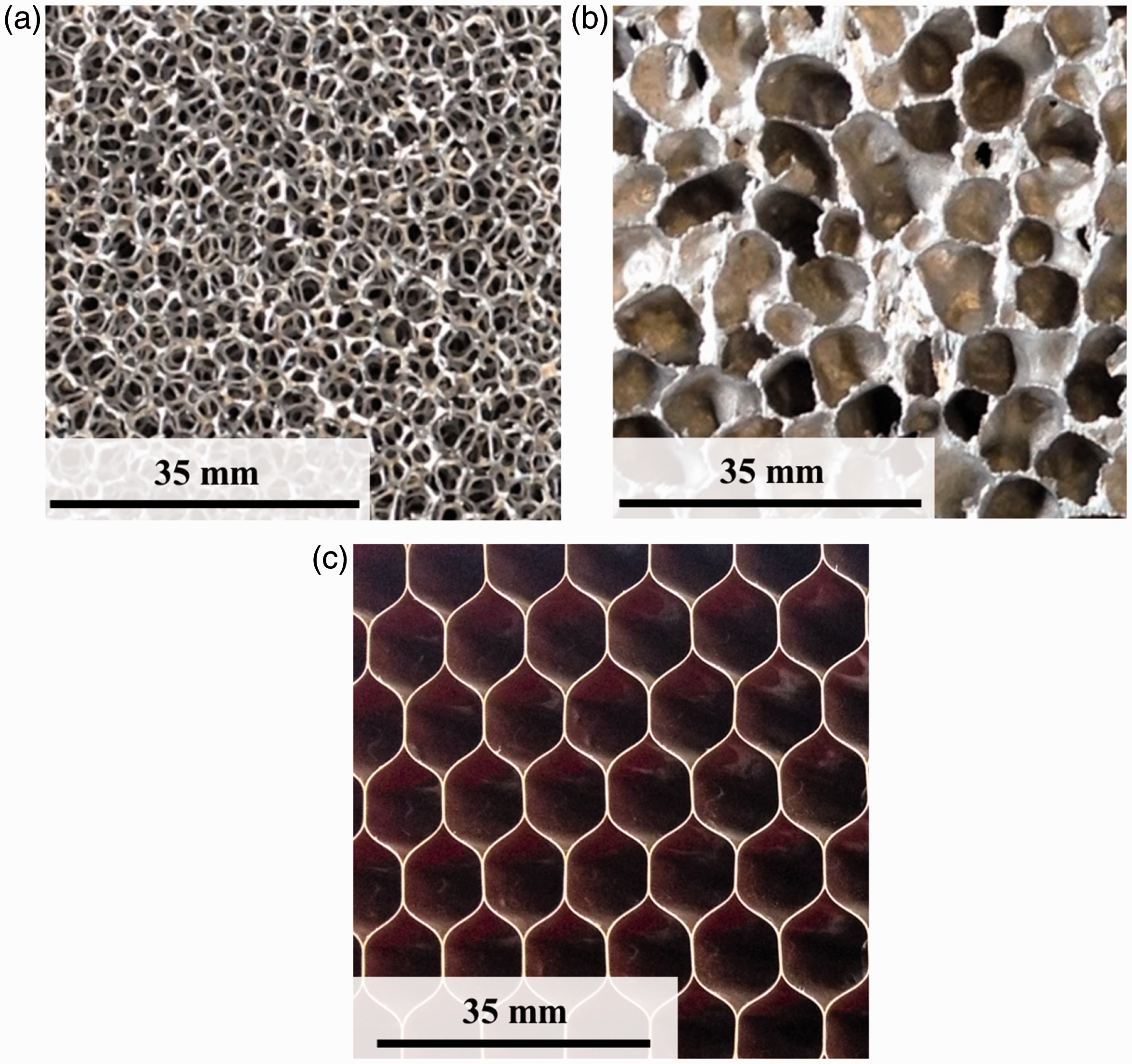
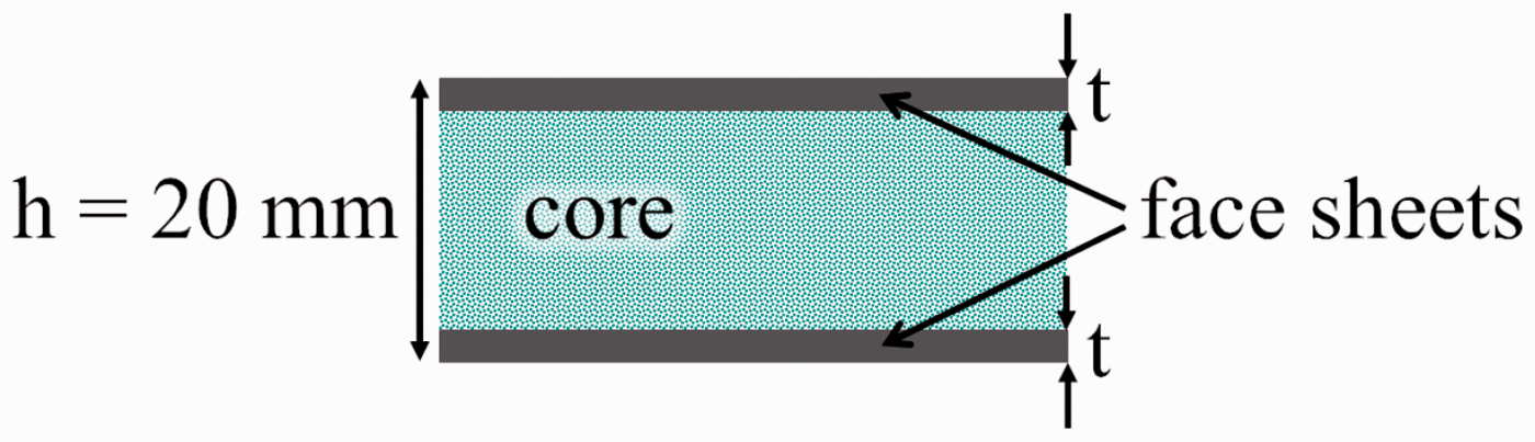
As face sheet, two types of carbon fibre fabric (woven with plain weave ‘Style 447 3K Aero’, non-crimp-fabric (NCF) ‘Dynanotex HS 15/80 DLN2’) were used, each with 160 g/m2 fibre area weight. Both fabrics were delivered by the company Lange + Ritter, Gerlingen, Germany. Three increments of fibre area weight per face sheet (160 g/m2, 320 g/m2 and 480 g/m2) were achieved by stacking one, two or three layers of fibre fabric, respectively. PUR foam (isocyanate ‘PUR 900’, polyol ‘PUR 569 IT’, supplied by Rühl Puromer, Friedrichsdorf, Germany) served as the matrix, and simultaneously as the interface of face sheet and core. The sandwich panels were manufactured through a modified PUR-spraying process (sequence shown in Figure 2): The face sheet fibre mats were connected loosely to the foam core structure (step 1). PUR resin was applied on both sides of the dry sandwich assembly, using a PUR-spraying nozzle mounted to a robot arm (step 2). The spraying path was defined by two straight lines separated by a margin of 160 mm, with a constant PUR discharge from 360 mm vertical distance. In order to avoid the handling of a wet sandwich assembly, which could result in fibre misalignment, the PUR resin for the lower face sheet was applied in a first cycle, directly into the mould cavity. After placing the dry sandwich assembly onto the resin inside the mould cavity, the robot arm applied the PUR for the upper face sheet in a second cycle with the same path, on top of the sandwich assembly. For curing, the mould cavity was closed to 20 mm distance of the cavity walls, with a curing time of 10 min at 60℃ (step 3). The PUR resin foamed during the curing process, infiltrating the face sheet fibres and then penetrating the outer part of the sandwich core. By this, a large connection surface between the PUR foam and the core structure was achieved, creating a stable bond of face sheets and core. As the density of the PUR foam is low compared to common adhesives, the increased connection surface did not increase the total sandwich mass. Further details on the PUR-spraying process are described by the authors in [23]. A sketch of the sandwich geometry is given in Figure 3. The specimens for testing were extracted from the sandwich panels (for dimensions, see ‘Experimental’ section) with a circular saw. For tensile testing, the face sheets were separated from the core with a band saw.
PUR-spraying production process of sandwich panels [23]: dry assembly of fibres and core, application of PUR onto dry assembly and curing inside heated mould cavity. PUR: polyurethane. Outline of the sandwich geometry.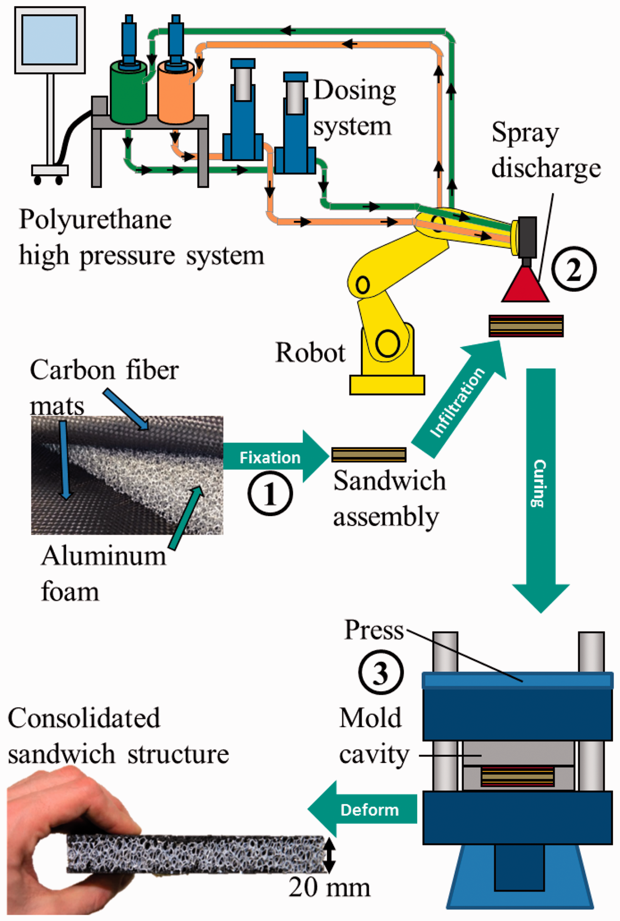
Measurement of density and geometry of specimens
For the calculation of effective densities, the mass of all cores and sandwich panels was measured using a scale with an accuracy of ±0.1 g. The geometric dimensions were measured with a sliding caliper (accuracy ± 0.05 mm) or – for dimensions >150 mm – with a ruler (accuracy ± 1 mm). The density value was achieved by dividing the measured mass by the measured volume. The resulting maximum error in computing for the effective density is less than 2%.
For the face sheet specimens, the thickness and density had to be investigated differently. As the fibres showed a slight waviness, the face sheets were extracted from the core with a margin to the fibres of approx. 1 mm to avoid a partial destruction of the fibre structure. Measuring the face sheet thickness directly with a micrometer caliper would therefore lead to inaccurate values of face sheet thickness. Furthermore, aluminium ligaments from the core remained on the face sheets due to the applied margin. Using the specimen mass for the calculation of the face sheet density would thus overestimate the density. Neither the residual aluminium foam ligaments nor the excess PUR foam surrounding the fibre package are expected to influence the stiffness of the face sheet, as their stiffness is very low compared to that of the carbon fibres.
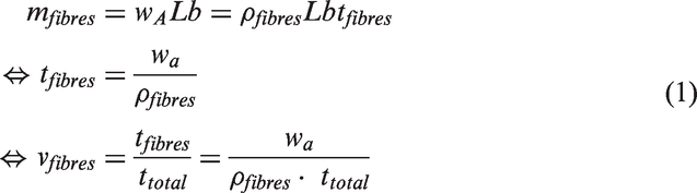
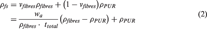
For these reasons, the thickness of the face sheet fibre package was measured by X-ray computed tomography (CT), using an Yxlon Y.CT Precision μCT-System. The X-ray-tube was operated at an acceleration voltage of 110 kV, at a current of 0.1 mA, using a tungsten target. In the scanned images, the fibre packages were contoured with a polygon face (see Figure 4). With the resulting area, divided by the specimen width, the average thickness ttotal of the fibre package was calculated. As the absolute fibre content in each specimen is known by the area weight wa of the fabric, the volume fraction of fibres vfibres can be calculated. Equation (1) shows the mass of the fibres as a product of the area weight wa, and the specimen length L and width b. ρfibres is the fibre density. The fibre volume content is then calculated using the virtual thickness of the fibre package tfibres (at 100% fibre volume fraction). Adding the PUR volume fraction vPUR = 1 − vfibres with the average PUR foam density ρPUR = 0.186 ± 0.007 g/cm3 equals the effective density of the face sheets ρfs (equation (2)).
Face sheet scanned using X-ray CT, with outlined measurement of fibre area. PUR: polyurethane; CT: computed tomography.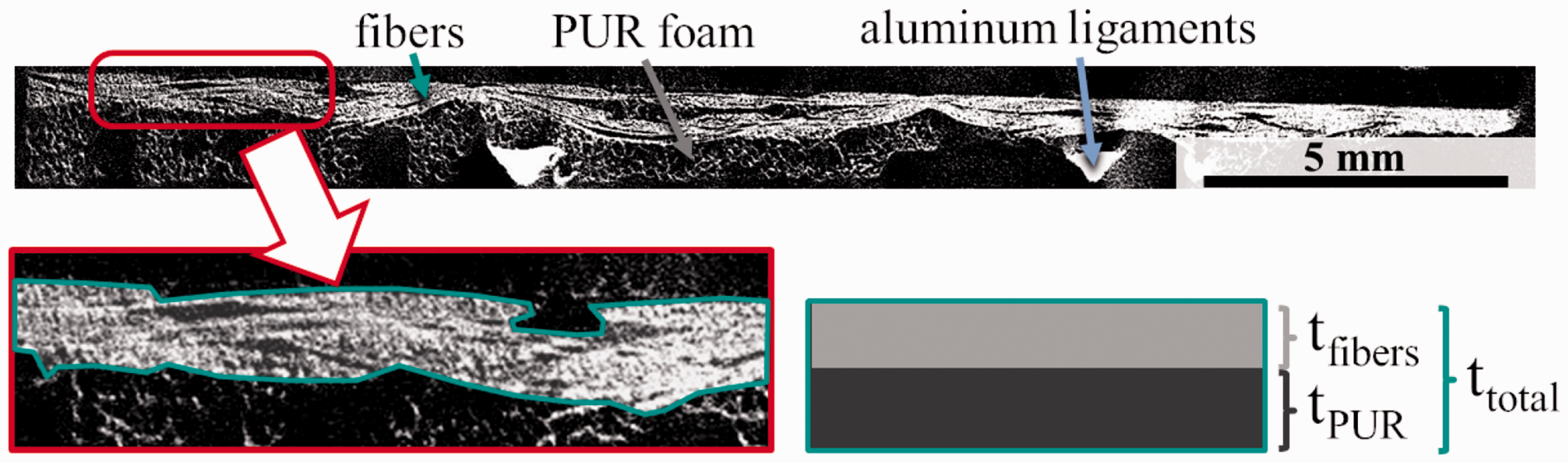
Calculation of sandwich stiffness
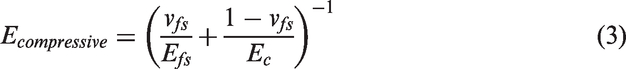
Using the measured Young’s moduli and densities of face sheet and core, a theoretical value of the Young’s modulus of the sandwich panel was calculated for two load cases (bending and compressive load), depending on the volume fraction of the face sheet (compared to the sandwich volume). For the compressive load, the Young’s moduli and densities of face sheet and core are combined by serial connection, as described by Hollaway [28]. For bending load, the moment of inertia is included, as described by Zenkert [1].
The volume content of the face sheet vfs inside the sandwich panel is
The Young’s modulus in bending load is calculated by isolating the effective Young’s modulus in the bending stiffness DSandwich, which contains the bending stiffness of the face sheets Dfs, the core Dc and the additional moment of inertia of the face sheets from the parallel axis theorem Dpat (see equation (4)). The face sheets are assumed to be entirely fixed to the core structure, as the ordinary theory of bending is used (compare [1]). As the face sheets are thin compared to the core, the core thickness is assumed to be approximately equal to the sandwich height h [1]. The effective bending modulus can be isolated from equation (4), see equation (5).


The volume content of the face sheet inside the sandwich panel vfs can be described with the effective density of the sandwich panel ρeff, which contains the density of the face sheets ρfs and of the core ρc (see equation (6)).

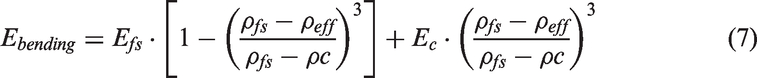
By eliminating νfs from equation (5) using equation (6), a function of Ebending and ρeff is created, see equation (7).
The resulting plot of Young’s modulus vs. density is displayed in Figure 5. Generic values of core and face sheet properties are used to display the shape of the modulus curves.
Example curves for calculated Young’s modulus of sandwich specimens in bending and compressive load (based on generic values for core and face sheet modulus) plotted vs. effective density.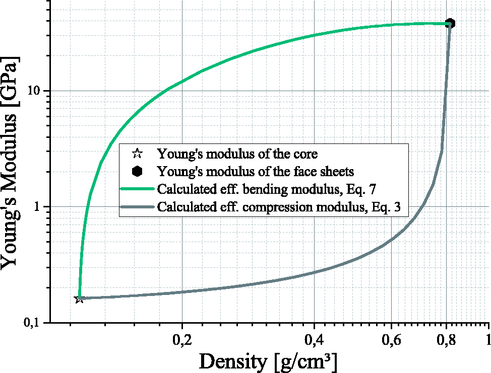
Experimental
Tensile test of the face sheets
Tensile tests of the face sheets were conducted following DIN EN ISO 527-5 at standard room temperature, with specimen type B (25 mm width, 250 mm length, for thickness, see ‘Measurement of density and geometry of specimens’ and ‘Face sheet thickness’ sections), using a ZwickRoell universal testing machine ZMART.PRO with a maximum tensile force of 200 kN and a load cell with a maximum load capacity of 20 kN. For uniform distribution of force, aluminium cap strips were applied to the specimens. The extension was measured using a ZwickRoell multiXtens at a gauge length of 100 mm.
Flatwise compression test of sandwich panels
Flatwise compression tests of the sandwich panels were conducted following DIN 53291 at standard room temperature, using a ZwickRoell universal testing machine ZMART.PRO with a maximum tensile force of 100 kN and a load cell with a maximum load capacity of 20 kN. The specimen size was generally 50 mm by 50 mm. Some specimens with larger sizes were included to verify the precision of measured density, yielding consistent test results. All specimens were produced with a core height of 20 mm, resulting in an average specimen height of approx. 20.7 mm with applied face sheets. The compression was measured using a tactile inductive incremental extensometer. The Young’s modulus was measured through an unloading cycle. For this, load was applied until 2.5% compression was reached, followed by a complete removal of the load and a reloading until failure. The Young’s modulus was taken from the linear section of the force-displacement-curve of the reloading procedure.
Bending test of sandwich panels
Four-point bending tests were conducted following DIN 53293 at standard room temperature, using a ZwickRoell universal testing machine ZMART.PRO with a maximum tensile force of 100 kN and a load cell with a maximum load capacity of 20 kN. The bending stiffness of the sandwich panels was determined through an unloading cycle similar to the approach in the flatwise compression tests (see previous section), with an initial load of 500 N before unloading. The loading span provided in the testing standard was set to 300 mm (outer span length) and 150 mm (inner span length), fitting the specimen length of 350 mm (see Figure 6). The adequacy of this adjustment was verified through further tests with 250 mm respective 125 mm span length, which yielded similar results. The average specimen height was 20.7 mm, with variations depending on the face sheet thickness, and with cores of 20 mm height. The lower loading bars were mounted on a hinge to prevent any reaction forces. During the tests, the specimens were continuously photographed with a digital single lens reflex camera, with the images matched to their corresponding measurement values. Similar approaches can be found in [26] and [27]. The deflection values for the load-displacement-curves of the inner loading bars and the specimen centre were taken from the images, calibrated with a scale bar and cross-checked with the crossbar position of the testing machine. The bending stiffness was calculated according to DIN 53293 using both the deflection values of the inner loading bars and the specimen centre. This calculation complies with the Timoshenko beam theory, including the consideration of shear deformation.
Test setup for four-point bending.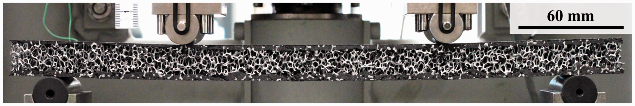
Results and discussion
Overview of symbols used in graphs.
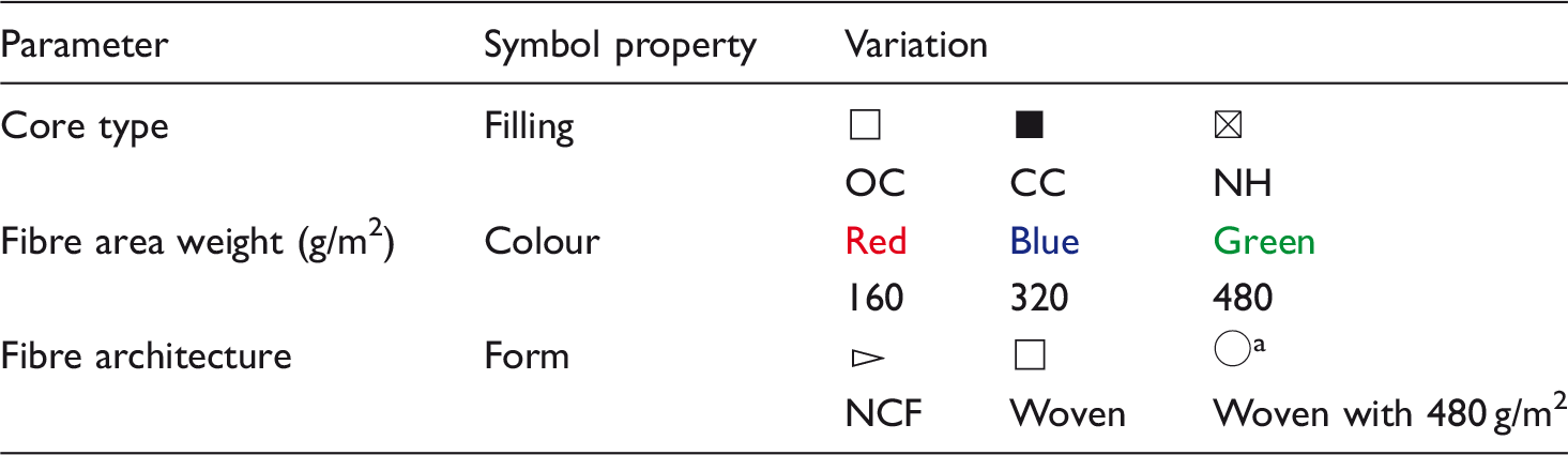
Different symbol as different PUR settings have been used due to infiltration issues.
OC: open cell; CC: closed cell; NH: Nomex honeycomb; PUR: polyurethane.
Face sheet thickness
Face sheet thickness of specimens with OC core, values in mm.
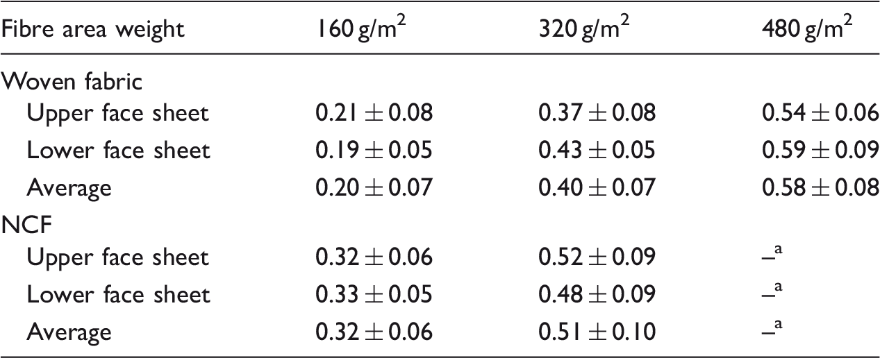
No specimens produced with this set of parameters due to poor infiltration quality.
OC: open cell; NCF: non-crimp-fabric.
Tensile stiffness of the face sheets
In Figure 7, the Young’s modulus of the face sheets is plotted vs. the face sheet thickness measured in CT scans. The Young’s modulus is calculated from measured values (compare ‘Experimental’ section) by dividing the tension (thus the force per cross section of specimen width b and thickness t) by the measured engineering strain ɛ:
Young’s modulus of face sheets vs. face sheet thickness, including extrapolation of Young’s modulus for each tested fibre area weight (red curve: 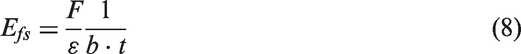
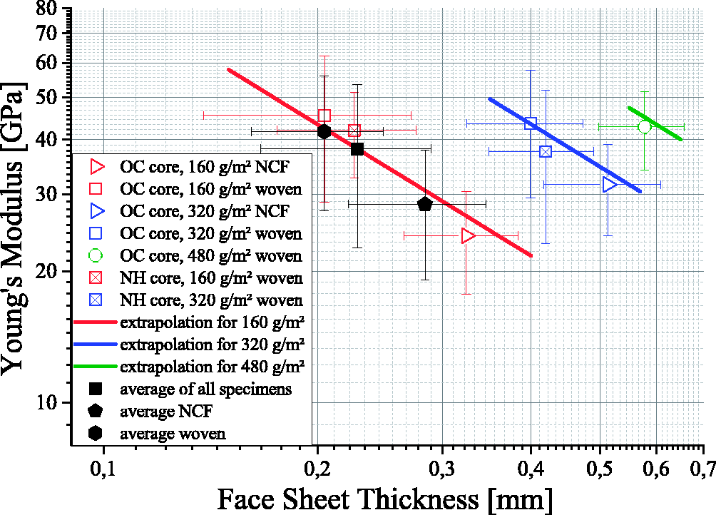
Assuming that only the fibres inside the face sheets are relevant for force distribution, the absolute tensile force per strain only depends on the amount (and therefore the area weight wa) of the face sheet fibres:
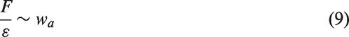
Within each parameter of fibre area weight, the absolute number of fibres is constant, and so is the force per strain. A variation of face sheet thickness therefore has to be the result of a varying volume fraction of PUR-foam matrix. The additional PUR foam adds to the cross section (decreasing the relative fibre volume content), but not to the tensile force per strain. Within each parameter of fibre area weight, the Young’s modulus therefore decreases with increasing face sheet thickness. With a constant specimen width b, equations (8) and (9) can be combined to equation (10):

This implies that the tested specimens have to be distinguished by their fibre area weight, as it affects the absolute tensile force per strain. The three tested area weights are visualized by the three different colours of the symbols used in Figure 7. As the three tested area weights are multiples of 160 g/m2 (achieved by stacking layers of 160 g/m2), the fibre area weight wa in equation (10) can be substituted by the number n of fibre fabric layers with 160 g/m2

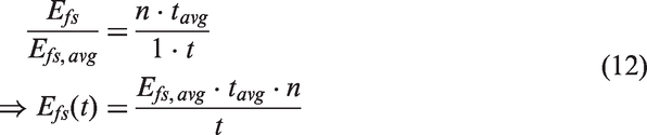
The creation of an extrapolation function of Efs and t valid for all tested specimens requires the consideration of the different fibre area weights. This is achieved by creating an average face sheet thickness per layer of 160 g/m2, tavg. Dividing E from equation (11) by the average Young’s modulus throughout all tested specimens Efs,
avg
, using tavg (and thus implying navg = 1), delivers a function of Efs and t, see equation (12).
The resulting extrapolation curves for each tested fibre area weight (thus
Figure 7 also confirms that the residual aluminium on the specimens did not influence the test results, as the Young’s modulus of specimens with aluminium foam cores does not differ from that of the specimens with honeycomb cores (and thus no residual aluminium).
Although the average Young’s modulus of the specimens with woven fabric is higher than that of the specimens with NCF fabric (see Figure 7, average normalized to area weight of 160 g/m2), the absolute tensile force per strain is approximately the same, as both averages fit the extrapolation well. The face sheet thickness t in equation (12) can be replaced by the effective density of the face sheet, using equation (2). With this, a function of 
The dependency of the fibre area weight is removed, as the quotient of n and wa always delivers the same value of
Plotting the Young’s modulus versus the effective density of the fibre package inside the face sheet specimens, Figure 8 shows an increasing Young’s modulus over the density, with no visible influence of the fibre area weight. As the fibre volume content has a linear correlation to the effective density, the increasing Young’s modulus is plausible. The extrapolation according to equation (13) shows good correlation to the measured values. The average density of all specimens also correlates well with the extrapolation, including the observed difference between the specimens with woven fabric and those with NCF. This indicates that the assumption of force distribution of the fibres (Young’s modulus), as well as the calculation of the face sheet density, is sufficiently accurate.
Young’s modulus of face sheets vs. effective density of face sheet fibre package, including extrapolation of Young’s modulus according to equation (13). OC: open cell; NCF: non-crimp-fabric; NH: Nomex honeycomb.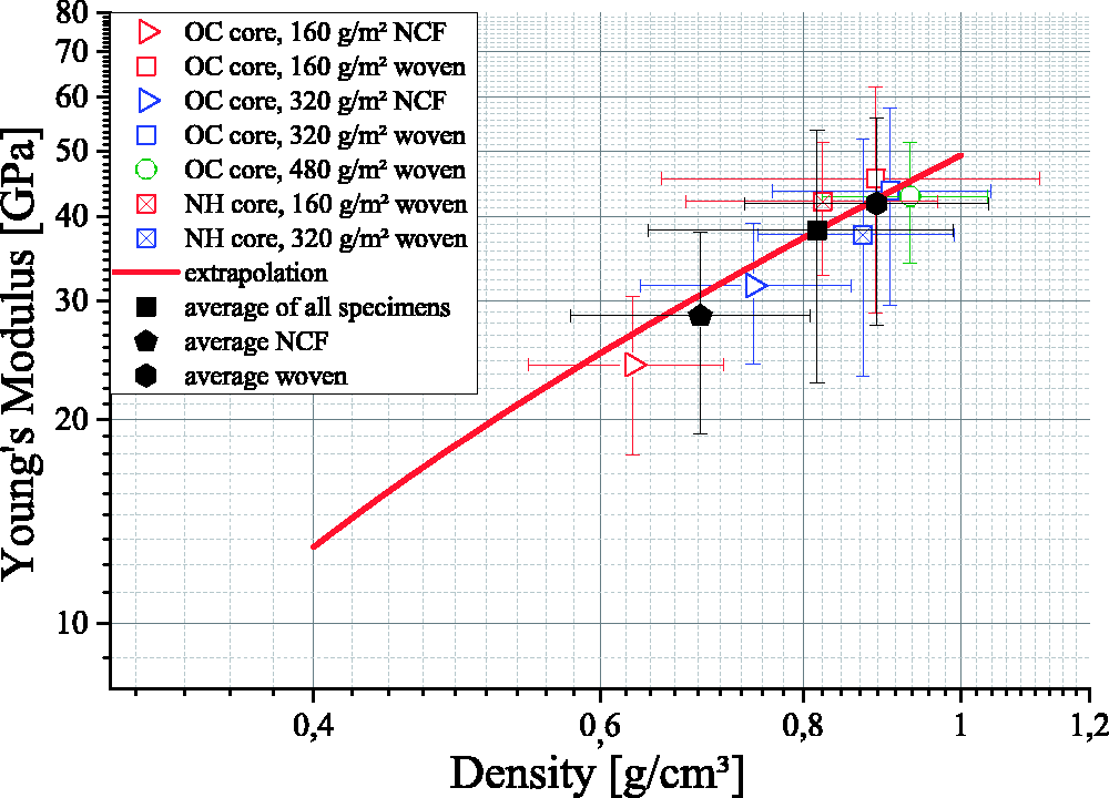
Flatwise compression stiffness of sandwich panels
Flatwise compression tests were conducted with sandwich specimens, although an investigation of only the core structure would seem a more obvious choice. Without the mechanical fixation of the core structure to the face sheets, the aluminium ligaments at the specimen surfaces touching the loading plates could deform in a different way than they would inside the sandwich structure. The usual approach to prevent this dissimilar deformation is to glue the core surfaces to stiff loading plates [3,29,30]. The PUR foam inside the core of the sandwich panels is not assumed to have a significant influence on the compressive stiffness. Similar observations were made by Dietrich [3] with NH cores and similar parameters for the PUR foam. As the tested NH cores show a smaller average Young’s modulus than the tested aluminium foam cores (113.3 MPa (NH) compared to 161.5 MPa (OC) and 355.1 MPa (CC), see Figure 9), the influence of the PUR on the aluminium core stiffness is expected to be equally negligible. Furthermore, the modelled compressive modulus graph (grey line in Figure 5) indicates a low increase from standalone core material to a sandwich with thin face sheets. The influence of the face sheets on the flatwise compression stiffness of the sandwiches can be neglected, as the fibre thickness is only approx. 1% of the sandwich height. Using sandwich specimens in compression tests instead of core structures glued to loading plates should therefore allow equally accurate measurements of stiffness, with a significantly reduced preparation effort for testing. Figure 9 shows the Young’s modulus of the sandwich specimens in flatwise compression testing. The three foam core structures are distinctly separated in their density values, with the NH sandwiches being the lightest, followed by those with OC cores and the CC sandwiches bearing the highest density. The scatter in the effective densities within each core structure parameter is caused by different densities of the core, as the configurations of face sheets and PUR interface are the same throughout all specimens. The Young’s modulus increases with the density throughout all tested core structures, as well as within the NH and the OC core structure.
Flatwise compression test results combined with density of foam cores, including a model of the Young’s modulus of open cell cores, taken from Ashby [31]. SW: sandwich.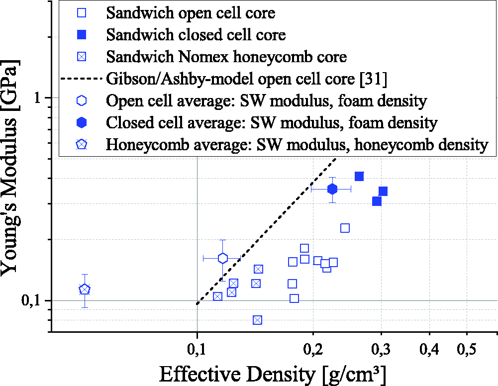
The model by Ashby et al. [31] implies a quadratic dependency of the Young’s modulus Ec and the effective density ρeff of a foam structure, with the values of the solid material Es, 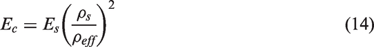
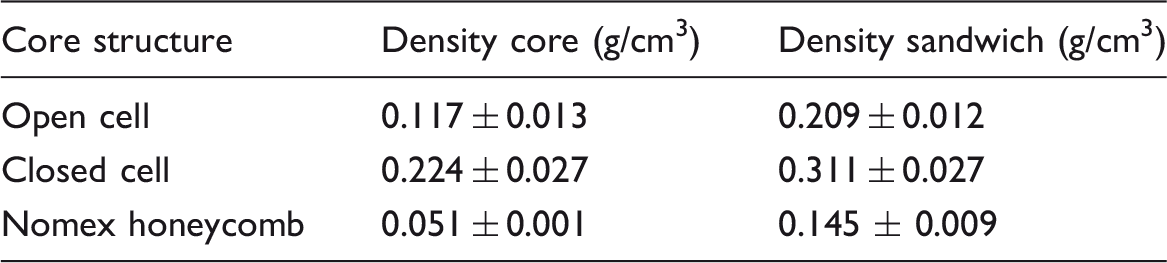
Effective densities of core structures and sandwich panels (values of sandwich specimens with fibre area weight 320 g/m2 per face sheet).
Bending stiffness of sandwich panels
Figure 10 shows the effective Young’s modulus in bending load of the tested sandwich panels vs. their effective density.
Young’s modulus in bending of sandwich specimens vs. effective density. OC: open cell; NCF: non-crimp-fabric; NH: Nomex honeycomb.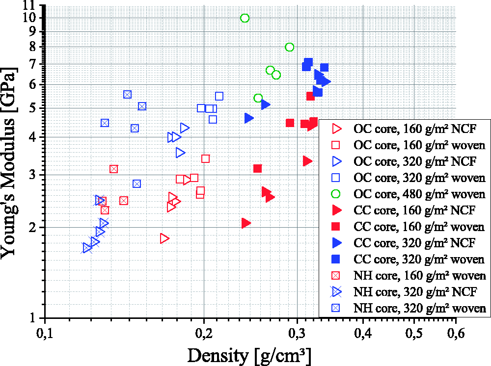
The Young’s modulus in bending load is mainly determined by the face sheet fibre area weight. With the exception of the NH NCF 320 g/m2 specimens, all stiffness values notably increase with the fibre area weight. This is an expected phenomenon, as the increased fibre area weight does not increase the face sheet stiffness itself (compare ‘Tensile stiffness of the face sheets’ section), but the absolute tensile force per strain, and the face sheet volume content
The face sheet architecture was not expected to influence either the Young’s modulus or the density. In the tensile tests of the face sheet, the Young’s modulus of the NCF specimens was lower than that of the specimens with woven fabric, but the absolute tensile force per strain was approximately the same (compare ‘Tensile stiffness of the face sheets’ section). The bending stiffness of the specimens with woven fabric was however observed to slightly exceed that of the NCF face sheet sandwich specimens.
The density is largely determined by the type of core structure. This has been discussed in ‘Flatwise compression stiffness of sandwich panels’ section and is also indicated in the graph of Figure 10, as the test results fall in three groups of density, separable by their core structure. Influences of the cell size on the density are minimized, as the specimen size exceeds the average cell size sufficiently. If at all, the NH structures with their regularly distributed cells could be slightly influenced by differently included numbers of cell walls.
The influence of the face sheet fibre area weight on the density is negligible: The difference of fibre weight in sandwich specimens with 320 g/m2 and with 160 g/m2 results in just 0.016 g/cm3 difference in density. The ostensibly observed influence of fibre architecture could be caused by a different resin-permeability of NCF and woven fabric during manufacturing, resulting in a slightly different amount of PUR contained inside the specimens.
Combination of core and face sheet properties with sandwich properties
Using the average values of Ec and ρc from the compressive tests of the core and the values of Efs and Young’s modulus in bending of sandwich specimens vs. effective density, with test results of compressive, tensile and bending tests. Curve of theoretical bending modulus from equation (5) for each combination of core and face sheet: dashed line for NCF face sheets, straight for woven. OC: open cell; NCF: non-crimp-fabric; NH: Nomex honeycomb.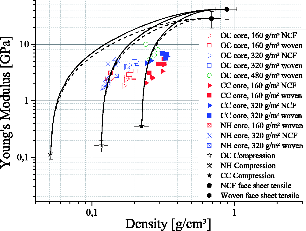
Comparing the model curves with the bending test results, the model seems to highly overestimate the Young’s modulus. Instead, the deviation of the tests results from the model is an underestimation of the density. The model only includes the face sheets and the core into the calculation of the density and neglects the PUR foam which connects face sheets and core. The density of this PUR foam inside each specimen could not be determined directly and was therefore eliminated as follows. The density value of each specimen was replaced by the sum of the corresponding average core density (
Figure 12 shows the influence of the described PUR quantity on the sandwich density, visualized by horizontal arrows. The length of the arrows, pointing to the left, represents the PUR density inside each sandwich specimen. The arrow tips are positioned at the density values of Young’s modulus in bending of sandwich specimens vs. effective density, with average test results of compressive, tensile and bending tests. Curve of theoretical bending modulus from equation (5) for each combination of core and face sheet: dashed line for NCF face sheets, straight for woven. Density of bending specimens calculated using equation (15). OC: open cell; NCF: non-crimp-fabric; NH: Nomex honeycomb.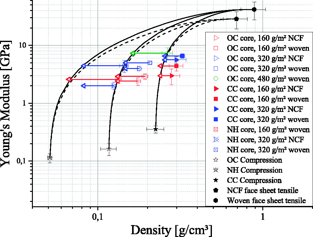
Srivaro et al. [20] achieve similar results with wooden sandwich structures. In contrast to the work at hand, they needed to include the shear modulus of the core in their calculations, since it was not negligible in contrast to the face sheet stiffness. Except for the core shear stiffness, the calculation of the sandwich stiffness is based on the same assumptions as in this paper. Srivaro et al. varied and investigated solely the core density instead of the overall sandwich density. Furthermore, they do not generally underestimate the experimental values with their calculated model. Combining these two observations supports the assumption of the PUR density influence visualized in Figure 12.
Conclusion
In the present work, novel sandwich structures with aluminium foam cores and CFRP face sheets, manufactured by a PUR-spraying process, were investigated. The relation of bending stiffness and sandwich density was evaluated.
Sandwich panels with CFRP face sheets and aluminium foam core could be manufactured. The penetration depth of the PUR foam into the core structures could be controlled by the amount of applied PUR, without flooding the OC core structures. The mechanical properties of specimens with different face sheet and core structures, produced with the same process routes, could be compared. The overall bending stiffness of the sandwich panels could be calculated using the mechanical properties of their single components core and face sheets. The calculation was validated by mechanical testing. OC aluminium foam cores result in a lower sandwich bending stiffness, but also in a lower sandwich density compared to the CC cores. The tested NH cores produce the highest stiffness-to-weight-ratio, especially with woven face sheet fibres. Within the face sheets, the assumption of load distribution solely by the fibres led to a function of the Young’s modulus depending on the face sheet thickness (or the face sheet density, alternatively), which correlated well to the measured values. The influence of the fibre area weight on the Young’s modulus could also be observed in the bending tests. The density values had to be measured using additional tests, such as X-Ray CT scans for the face sheets. This increased the computational error bar, but still led to accurate results. All values used in this work (except for the carbon fibre density and the values for bulk aluminium) were gained experimentally and did not have to be taken from literature. The prediction of the relation of sandwich bending modulus and sandwich density using the common models of sandwich stiffness overestimates the sandwich stiffness-to-weight-ratio. This overestimation was found to be caused by the additional weight of the PUR foam connecting the face sheets to the core. The PUR foam was not observed to have an influence on the stiffness of the sandwich. If the weight of PUR foam interface is included in the value of sandwich density, the prediction of sandwich stiffness-to-weight-ratio fits the measured values satisfactorily, throughout all tested variations of core and face sheet structure. In conclusion, it was found that the bending stiffness and density of sandwich panels produced by PUR-spraying process could be predicted throughout all tested specimens, using the same model based on the properties of their components face sheet and core, although their core structures were highly different in their constitution and their mechanical properties.
Footnotes
Acknowledgements
The authors would like to acknowledge the participation and support of Florian Wafzig (Fraunhofer ICT, manufacturing the sandwich panels), and the technicians at the labs at KIT IAM and Fraunhofer ICT.
Declaration of Conflicting Interests
The author(s) declared no potential conflicts of interest with respect to the research, authorship, and/or publication of this article.
Funding
The author(s) disclosed receipt of the following financial support for the research, authorship, and/or publication of this article: This paper is based on investigations for the project EL 473/6-1, ‘Manufacturing, testing and modelling of hybrid aluminium foam-CFRP sandwiches with improved impact strength’, which is kindly supported by the German Research Foundation (DFG).