
Abstract
In this paper, the connection stiffness between a thin-walled Z-beam and a sandwich panel is investigated by means of laboratory experiment, analytical approach, and numerical simulation. The scheme of the conducted experiment refers to a double lap shear test. The two thicknesses of the sandwich panel (100 mm and 60 mm) and two groups of fasteners (four and three) were investigated. The laboratory tests allowed for the determination of the failure mechanisms and the prediction of the reliability of the restraint of the thin-walled beam, provided by sandwich panels. The assumed finite element model created in Abaqus/CAE consisted of solid finite elements (core layer of the sandwich panel, roller support) and shell finite elements (thin-walled beam, facings of the sandwich panel). The fasteners were modeled implicitly, i.e. using spring connectors. The stiffness of the spring connector was determined on the basis of the derived analytical expression and the laboratory test results. The kinematical response of the adopted finite element model was in agreement with the laboratory results. Such a model can be used to verify more complex finite element models with explicitly introduced fasteners.
Introduction
In building applications, sandwich panels and thin-walled beams are elements of roof and wall cladding systems. The sandwich panels are composite elements which consist of a thick, soft core and two thin, stiff external facings. The sandwich panels, as well as the thin-walled beams, are characterized by a high load-bearing capacity coupled with a small weight. In the case of sandwich panels, designers must take into consideration a number of failure mechanisms, see [1–3]. In the case of thin-walled elements, designers must take into consideration the sensitivity to local and global loss of stability, see [4]. An interesting analytical investigation, based on the Vlasov approach, concerning the problem of lateral restraint of thin-walled beams, was presented in [5,6].
The fact that thin-walled elements can be restrained by trapezoidal sheeting is well known and widely used by structural engineers. Recently, it is assumed that the global stability of thin-walled elements can be also improved by sandwich panels. The phenomenon of the interaction between the sandwich panel and the thin-walled beam was considered by a number of authors. For example, in [7], experimental and numerical studies (based on the test bed given in Eurocode 3 [8]) were performed to estimate the rotational restraint of thin-walled Z-sections provided by sandwich panels. The presented approach was applicable for gravity and uplift load. Unfortunately, the contact effect between the thin-walled beam and the sandwich panel facing resulting from a gravity load and mechanical properties of the sandwich panel core was not taken into account. These problems were noticed and described by Dürr et al. [9]. Moreover, Dürr in his PhD thesis [10] presented full scale experimental and numerical investigations, which determined the shear and the torsional restraint effect provided by sandwich panels. The majority of the results presented in the above-mentioned PhD dissertation are included in the European Recommendations on the Stabilization of Steel Structures by Sandwich Panels [11]. Furthermore, the rotational resistant stiffness of a connection between the thin-walled Z-beam and the sandwich panel was also investigated in [12]. This paper demonstrated that the number and the localization of the fasteners (spacing and position with respect to Z-beam web) had a predominant effect on the thin-walled beam rotational stiffness. Recently, full-scale laboratory tests of sandwich panels connected with thin-walled beams were presented in [13]. The paper presented the results of the quasi-cyclic load, showing that the dissipation of the energy was manifested by the plastic deformations of the angle support cleats. It turned out that default support cleats (i.e. those used by the manufacturers of thin-walled elements) are too flexible.
Problem formulation
In this paper, the connection stiffness between a thin-walled Z-beam and a sandwich panel is investigated by means of laboratory experiments, analytical approach, and numerical simulations. The main aim of this paper is to determine the influence of the shear load (i.e. the load perpendicular to the axis of fasteners) on the durability and the connection stiffness between a thin-walled beam and a sandwich panel. The static and the quasi-cyclic loads were considered. The failure mechanisms obtained from the laboratory tests make it possible to assess the reliability of the restraint of the thin-walled beam provided by the sandwich panel. Furthermore, the influence of the varied sandwich panel thicknesses and the varied number of fasteners on the connection stiffness is investigated.
The test bed scheme has been prepared and modified with respect to the experimental test bed described in [12,14]. This test bed refers to the double lap shear test. Usually, the double lap shear test can be used to determine the correct value of the shear modulus of the foam core of a sandwich panel, see [15]. Furthermore, this type of test can also be used in other composite structures (aluminum–concrete, steel–concrete, steel–wood, and aluminum–wood). For instance, in [16], the double lap shear test was used in order to verify a new type of shear connectors used in aluminum–concrete structures.
Experimental approach
Definition of an experiment procedure and description of the laboratory test bed
The test bed presented in Figure 1 consists of the fasteners (1), the sandwich panels (2), and the thin-walled Z-beams (3). The support base (4) provides assumed boundary conditions. The test bed is stable due to the symmetrical arrangement of elements.
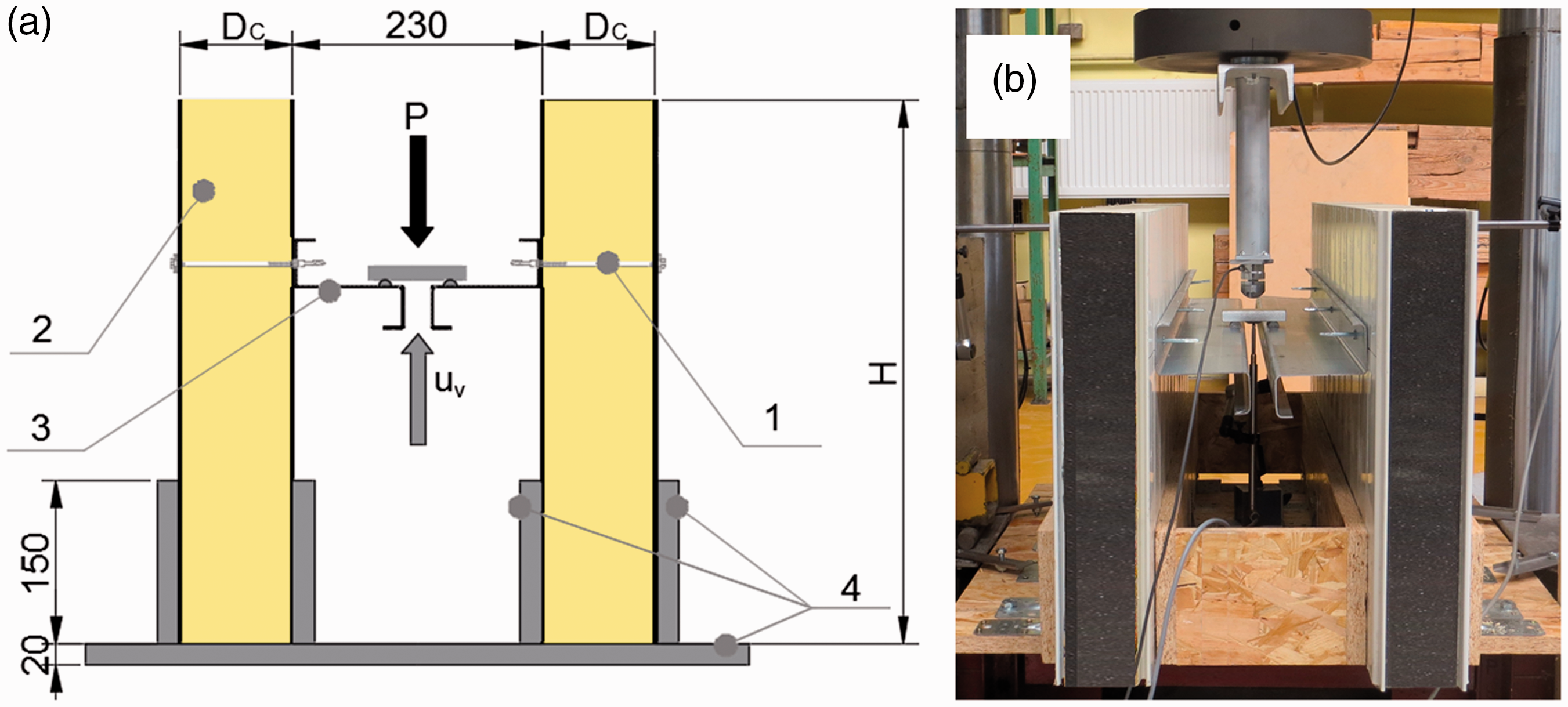
Double lap shear test bed: (a) scheme of the test bed and (b) view of the real test bed.
The varied number (n) of fasteners (n = 3 and n = 4) and the varied thicknesses (DCi) of the sandwich panel core layer made of a polyizocyjanurate (PIR) foam (nominal thicknesses are as follows: DC1 = 60 mm and DC2 = 100 mm) were investigated. The nominal thickness of the external and the internal steel facings of a sandwich panel was tF = 0.5 mm. The length of the sandwich panel was equal to 1150.0 mm, while the height was H = 500 mm. The thin-walled beam cross section used in the experiment is depicted in Figure 2. The measured thickness of cross section walls of the thin-walled beam was equal to tb = 1.502 mm.
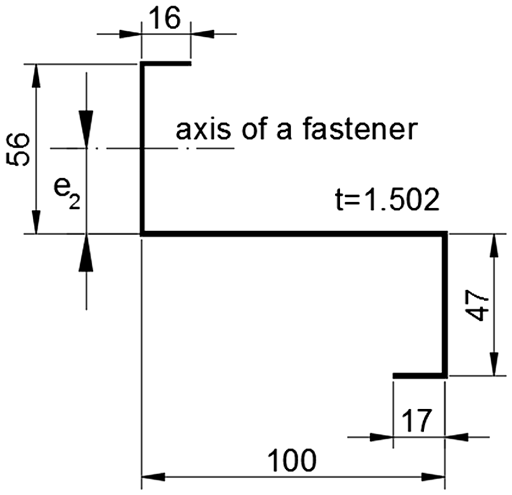
Cross section of the thin-walled beam.
In the case of the core layer made of a PIR foam, the hyperelastic material model was used. The data for the hyperelastic model were adopted from tests performed and described in Studziński and Pozorski [17]. The mechanical properties of the material of a thin-walled beam and facings – steel – were obtained by a tensile test, in accordance with the EN-ISO 6892-1 standard [18,19]. Note that in finite element (FE) analysis the elastic–plastic model of the thin-walled beam and facings were adopted, and thus, only the necessary material parameters are listed in Table 1.
Selected mechanical properties of a thin-walled beam and sandwich panel facings.
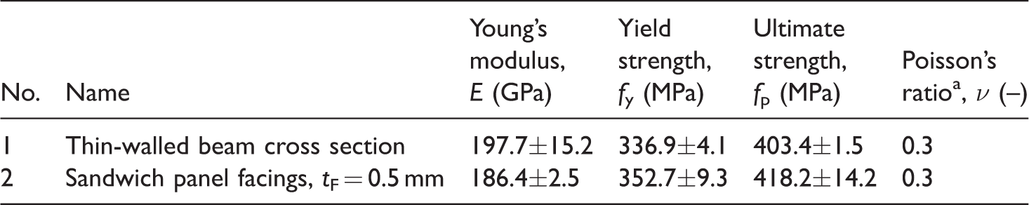
The parameter obtained from subject’s literature.
During the experiment, the vertical displacement of the middle point of thin-walled elements (uV) and the applied force (P) was measured, see Figure 1. To measure the displacement, the inductive displacement transducer with nominal displacement 50 mm was used (WA 50). The testing machine Instron 8805 was used in the experiment. Note that due to the small range of the force in the experiment (P ≤ 4.0 kN) its value could not be directly measured by the testing machine Instron 8805. The testing machine is characterized by 1000 kN capacity of the load cell and is of the class 0.5. These characteristics of the testing machine give an accuracy of 5 kN (1000 kN⋅0.5%). Therefore, the additional force transducer (U93) was used, see Figure 1(b). The force transducer is of the capacity 10 kN and is of the class 0.5 (i.e. it gives the measurement of the force with 0.05 kN accuracy). The speed of the displacement of a piston of Instron 8805 was equal to 0.5 mm/s. During the tests, three load levels were investigated: PI ≅ 2.0 kN, PII ≅ 3.0 kN, and PIII ≅ 4.0 kN. The adopted load levels were designed in order to recognize the following two aspects. The assumed first load level (PI) uniform for all cases, i.e. (n = 3, 4 and DCi = 60 mm, 100 mm), defines the connection stiffness as a function of both the sandwich panel core thickness and the number of fasteners. For sandwich panels with the core 100 mm in thickness, the two additional load levels were investigated, namely, for n = 3 the second load level (PII) was applied and for n = 4 the third load level (PIII) was applied. The comparison of the mechanical responses of the connection between the thin-walled beam and the sandwich panel for equal shear forces per fastener (but with a different number of fasteners, i.e. FV,Ed( n = 3) = PII/6 = 3.0 kN/6 = 0.5 kN and FV,Ed( n = 4) = PIII/8 = 4.0 kN/6 = 0.5 kN) is possible because of the two load levels mentioned above. Additionally, the optical measurement system called Aramis was used in order to obtain the strain and displacement fields at the external facing of the sandwich panel in the vicinity of the fasteners, see Figure 3. The Aramis allows for high-precision three-dimensional (3D) measurements by using two independent stereo cameras, placed on a special frame. Furthermore, the Aramis enables precise measurements of 3D displacements, velocities, accelerations, surface strains, and evaluations of six degrees of freedom.

View of a test bed with the Aramis optical measurement system.
The Aramis with the stochastic patterns set (see Figure 4) delivered 3D coordinates of the test sample to the GOM Correlate Professional software [20]. Images and analogue data recorded during the experiment were synchronized with the testing machine Instron 8805. The recording time was set to 2 Hz (the same as the speed of the Instron piston displacement). In the presented laboratory tests two 6 MP cameras with 2752 × 2200 resolution were used (a single pixel was 4.54 μm), while the size of the measurement field was 150 × 150 mm.
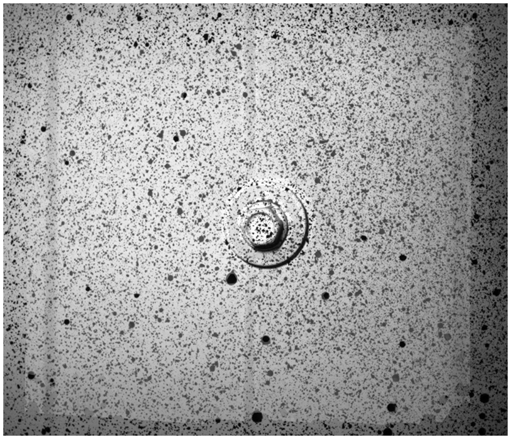
The stochastic pattern applied to the analyzed measurement object.
Discussion of laboratory results
For the three load levels, the delamination between the facings and the core was not observed, and neither was the shear failure of the core. Indentation at the external facings in the vicinity of the fasteners was observed. The Aramis optical measurement system makes it possible to determine the size of the indentation. Figures 5 and 6 present the maps of the deformations in the vicinity of the fasteners of the external facing of the 100-mm sandwich panel. In the case of the three fasteners, n = 3 (see Figure 5), the measurement mesh covered the area of the external facing, while in the case of four fasteners, n = 4 (see Figure 6), the measurement mesh also covered the area of the fastener head (the ring in Figure 6).
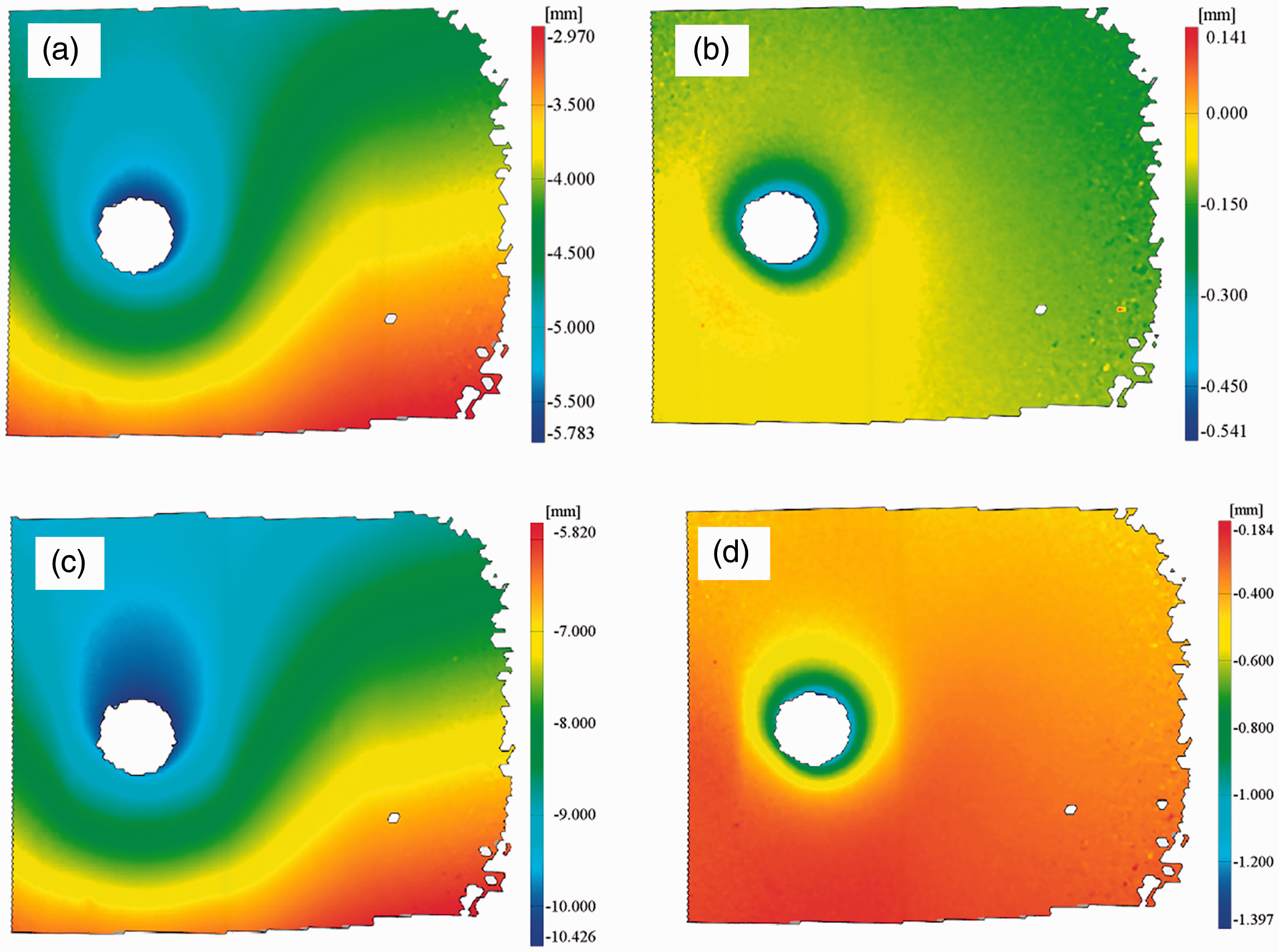
The maps of deformation. Three fasteners (n = 3). Varied load levels: (a) P = 1.0 kN (first load cycle), (b) P = 0.0 kN (unload after first load cycle), (c) P = 1.5 kN (11th load cycle), (d) P = 0.0 kN (unload after 11th load cycle).
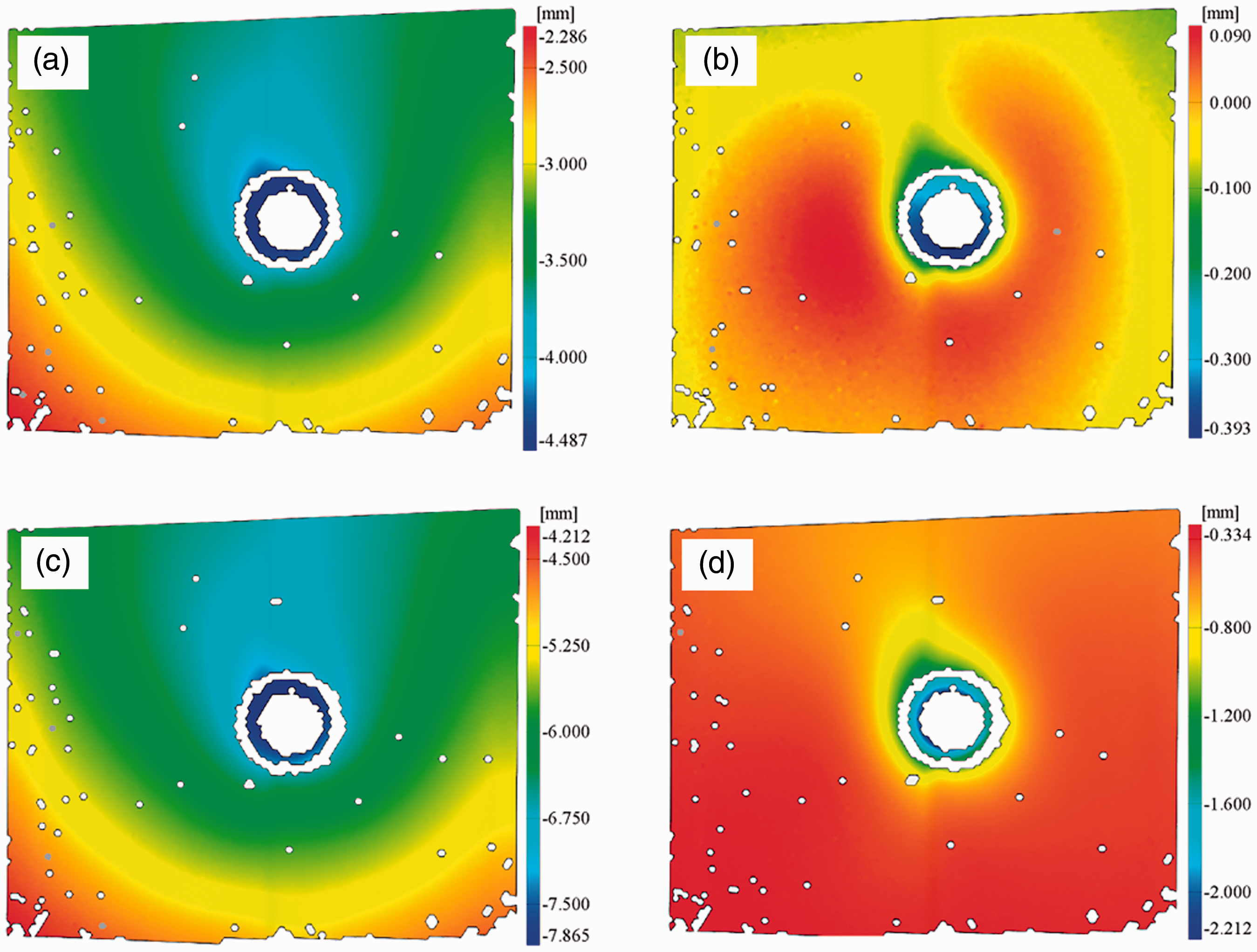
The maps of deformation. Four fasteners (n = 4). Varied load levels: (a) P = 1.0 kN (first load cycle), (b) P = 0.0 kN (unload after first load cycle), (c) P = 2.0 kN (11th load cycle), (d) P = 0.0 kN (unload after 11th load cycle).
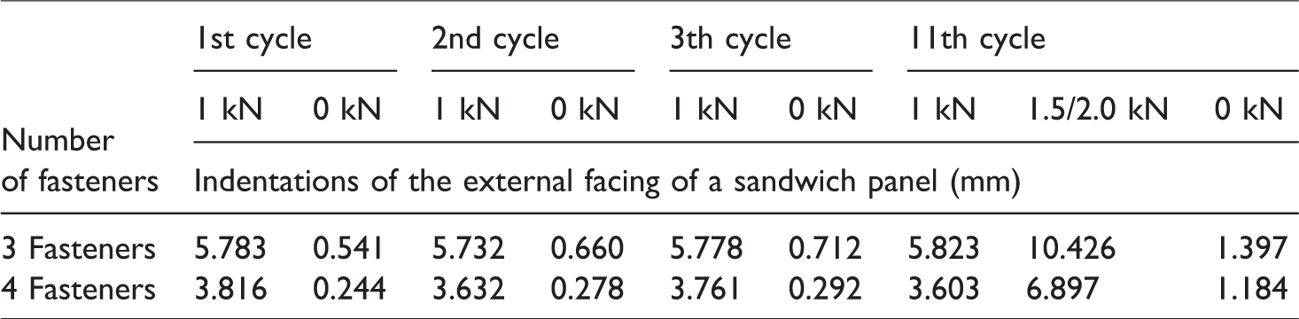
Table 2 presents the maximal values of deformations of the external facing for three and four fasteners and the varied loading and unloading cycles. It was observed that after the first load and unload cycle the permanent indentations remained.
The values of maximal indentations of the external facing in the vicinity of the fasteners for varied loading and unloading cycles and various number of fasteners.
Moreover, the ovalization of the holes was observed during the performed laboratory tests. Since the thin-walled beam walls are three times thicker than sandwich panel facings, while having similar plastic strength, the ovalization was limited to the facings. For the first load level the shear forces per fastener were 0.33 kN for n = 3 and 0.25 kN for n = 4. As previously mentioned, the shear forces per fastener for the second and the third load levels were 0.50 kN. In the experiment for the first load level (PI) under static and quasi-cyclic load, ovalizations were not observed (see Figure 7(a)). Nevertheless, for the second and third load levels, the ovalization appeared (see Figure 7(b)). This means that the bearing capacity of the external facings of the nominal thickness 0.5 mm is smaller than 0.5 kN.
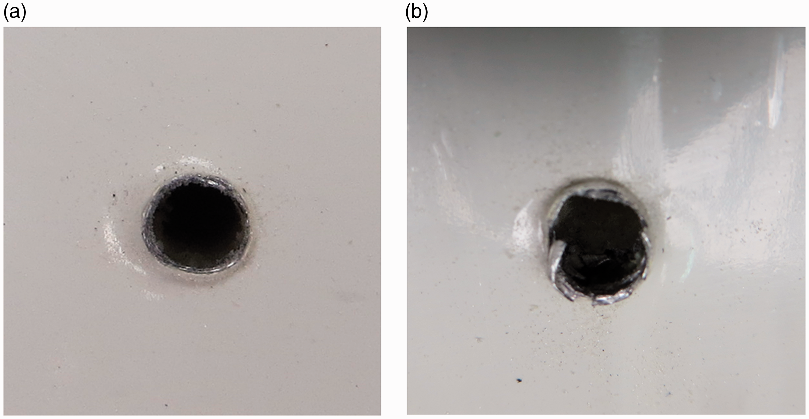
The view of the holes in the internal facing of a sandwich panel with core thickness 100 mm: (a) no ovalization of the hole – static and quasi-cyclic load, first load level, n = 3, 4 and (b) ovalization of the hole – quasi-cyclic load, second and third load level, n = 3, 4.
The static and the quasi-cyclic loads were performed in the laboratory experiments. The results for the first load level of a static load (of the sandwich panel 60 mm and 100 mm in thickness, connected with the thin-walled Z-beam by three and four fasteners) are presented in Figure 8. The load paths which are depicted in Figure 8 represent the vertical displacement of the middle point of the thin-walled beam (uV). Note that the increase of the core thickness, as well as the increase of the number of fasteners, reduces significantly the vertical displacement uV, i.e. the connection is stiffer.
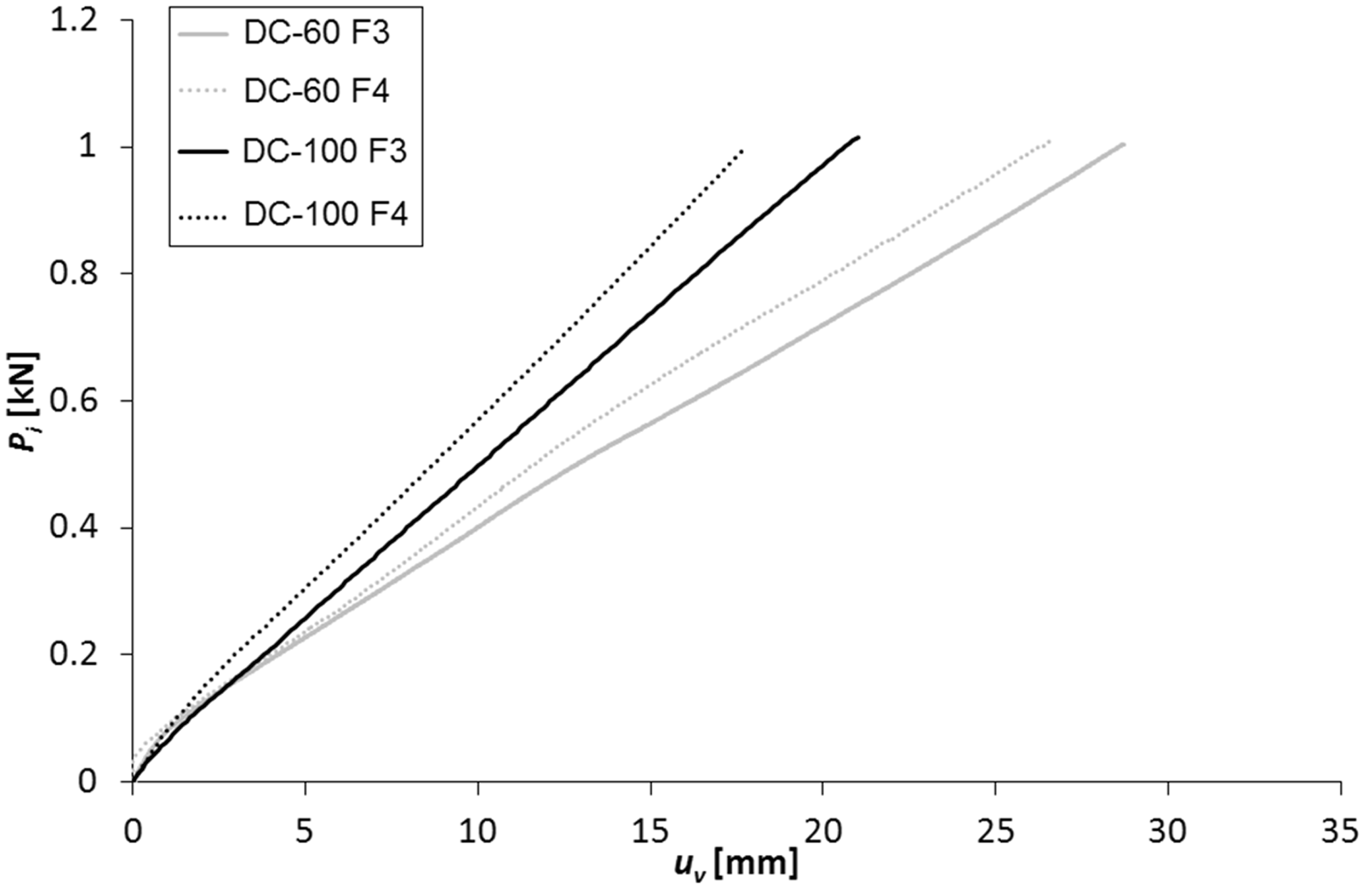
First load level of a static load. The selected load paths of a vertical displacement of the middle point of a thin-walled beam uV of a sandwich panel with core 60 mm and 100 mm in thickness.
The results of the quasi-cyclic load are presented in Figure 9. The thickness of the core was 100 mm; three fasteners were used. It was observed that the unload equilibrium paths did not coincide with the reload ones. They formed hysteresis loops, which shifted horizontally without changing their size and shape. This phenomenon in literature is called ratcheting behavior, see [21]. It is also worth mentioning that, in the case of the first load level, ovalization was not observed and the dissipation of energy was the result of the indentation of the external facing in the vicinity of the fasteners and the slipping of the thin-walled beam flange along the fastener axis. However, ovalization was observed in the case of the second load level, i.e. the dissipation of energy was additionally manifested by the ovalization of the internal facing holes.
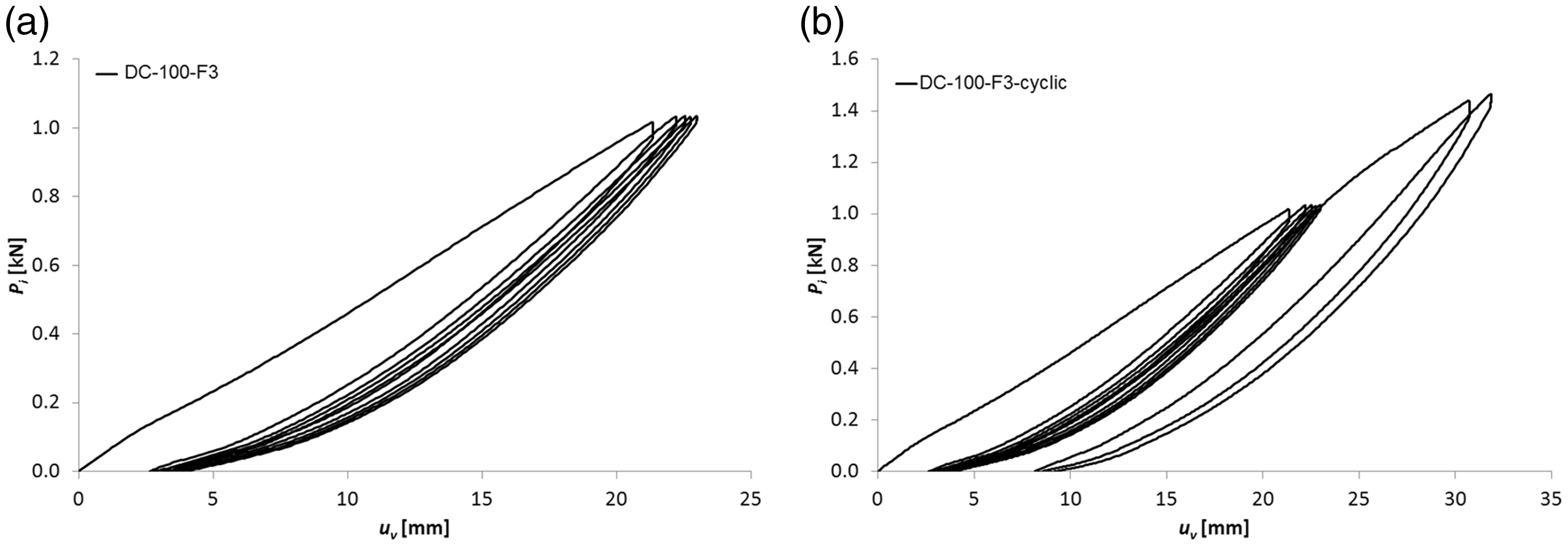
The equilibrium paths of the quasi-cyclic load of the sandwich panel with core 100 mm in thickness (n = 3): (a) load–unload paths for the first load level and (b) load–unload paths for the second load level.
Analytical approach
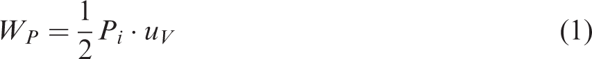
Equations (1) and (2) and the results obtained from the experiments were used to determine the stiffness of a spring element introduced in the FE model. The spring elements in the FE model were used in order to model the fasteners’ behavior, which also resulted in the simplification of the numerical computations. It is assumed that the spring elements with correctly defined stiffness may provide the true mechanical response of the connection under investigation. According to the scheme depicted in Figure 10, the mechanical work of the force Pi on the displacement uV and the mechanical work of the spring on the displacement x is expressed by equations (1) and (2), respectively

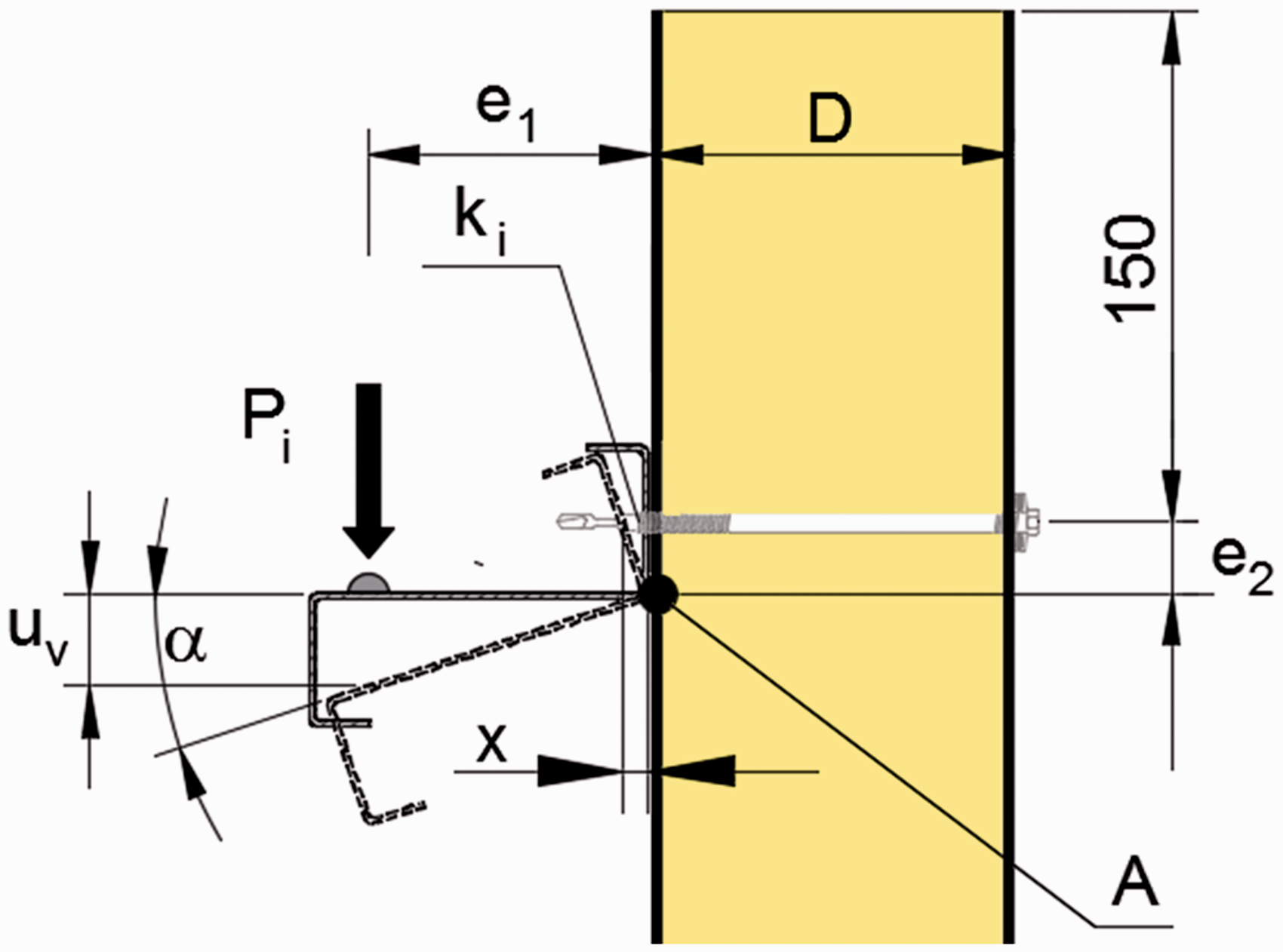
The scheme for the analytical model.
In this case, the law of the conservation of energy states that the work of the Pi force on the uV displacement has to be equal to the work of the spring on the x displacement: WS = WP. The geometrical relation between the vertical displacement uV and the elongation of the spring x is expressed by equation (3)
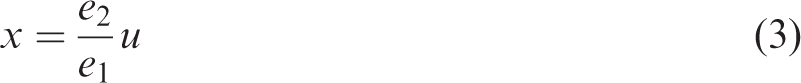
Simultaneously, it is assumed that the contour of the thin-walled beam remains unchanged. This assumption for the investigated load level was confirmed in the experiment. Using equations (1) to (3) and the work–energy principle, the expression for the spring stiffness takes the following form
Numerical approach
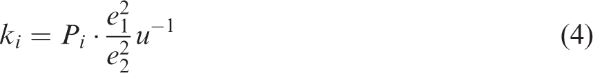
The assumed FE model which was created in the Abaqus/CEA environment consisted of solid finite elements (core layer of the sandwich panel) and shell finite elements (facings of the sandwich panel and the thin-walled beam). The solid finite element is a hexagonal, eight-node linear brick element with reduced integration (C3D8R), while the shell finite element is a quadratic, four-node doubly curved thin shell element with reduced integration (S4R). Figure 11 presents different mesh sizes which were used in the FE model,
The visualization of the meshes in FE model in Abaqus/CAE environment.
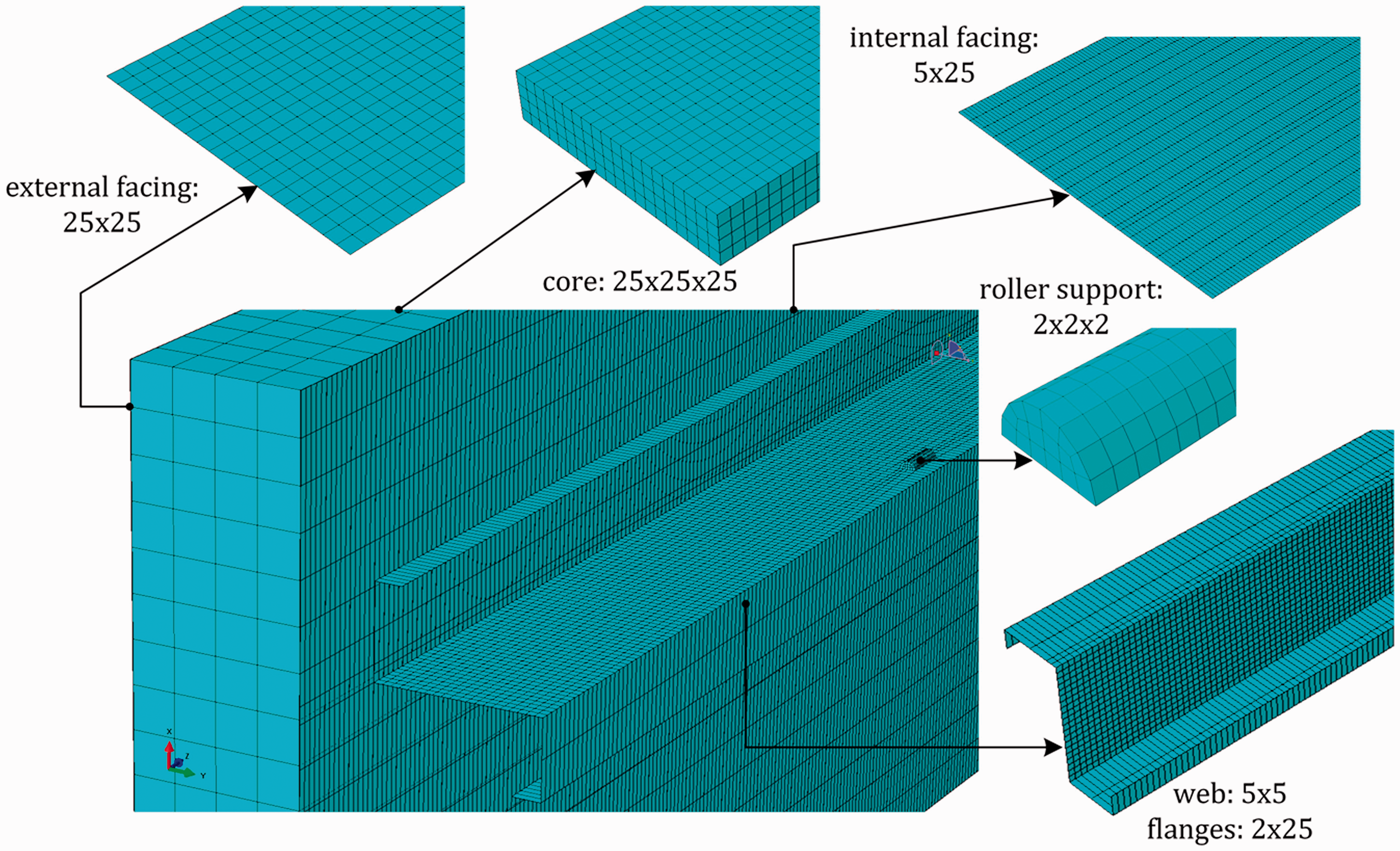
The normal contact definition was introduced between the internal facing and the thin-walled beam with no penetration possibility between these elements. The Newton–Raphson nonlinear analysis was performed. In the case of the facings of the sandwich panel and the thin-walled beam, the elastic–plastic material model was assumed, see Table 1. In the case of the core layer, the hyperelastic material model was adopted from the tests performed and described in [17]. The fasteners were modelled implicitly, i.e. using spring elements (SPRING2) with stiffness obtained from equation (4). The axial spring stiffness for n = 3 and n = 4 was equal to 178 N/mm and 162 N/mm, respectively. The SPRING2 element in Abaqus/CAE defined the spring behavior between two nodes and was characterized by the fixed direction of acting. According to the Abaqus/CAE documentation [22], the relative displacement across the SPRING2 element Δu is expressed by equation (5)

The characteristic of the SPRING2 element in Abaqus/CAE: (a) “compressive” spring and (b) “tensile” spring.
The kinematical response of the numerical model is presented in Figure 13.
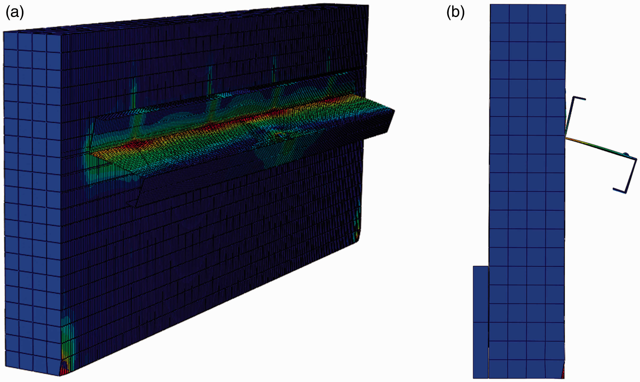
Numerical kinematical response of the sandwich panel with core 100 mm in thickness connected with the thin-walled beam using four fasteners: (a) isometric view of the numerical model and (b) front view of the numerical model.
The verification of the FE model was carried out by sandwich panels with core 100 mm in thickness, see Figure 14.
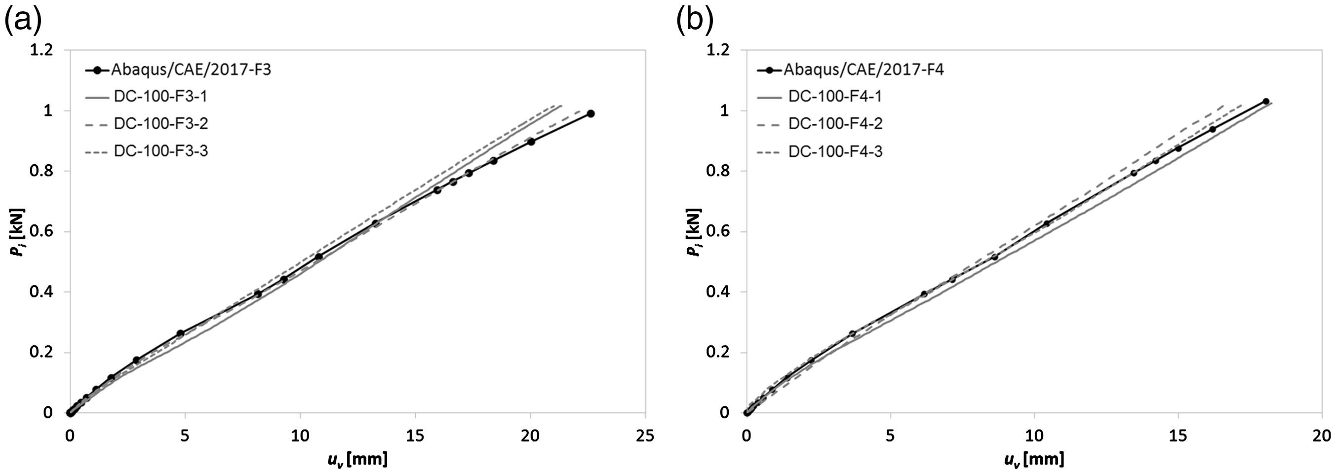
The load paths of the sandwich panel with core 100 m in thickness for the first load level. Connection provided by three (a) and four (b) fasteners.
In Figure 14, the gray lines (continuous, dashed, and dotted) refer to the experiments performed in the laboratory, while the continuous black lines refer to the results of the FE model. The obtained correlation between the experimental approach and the FE simulation is satisfactory for three (n = 3) and four (n = 4) fasteners. This means that both the suggested FE model with an implicit definition of the fasteners and the analytical approach are suitable for the determination of the kinematic response of the connection. Note that there are small differences between the laboratory trials (gray lines in Figure 14). They arose from the unintended yet unavoidable differences in the position of the fasteners with respect to the thin-walled beam (e2 parameter). Thus, the small variations of the e2 (the spacing between fastener axis and beam web, see Figure 10) in the experiment were observed (e2 ∈⟨24 mm, 29 mm⟩).
Conclusions
The double lap shear test adopted in the research allows for an investigation of the rotational stiffness of the thin-walled beam connected with the sandwich panels. It can be concluded that both the number of fasteners used to connect the thin-walled beam with the sandwich panel and the thickness of the sandwich panel have influence on the rotational stiffness. The quasi-cyclic tests revealed both the ratcheting behavior of the connection and the problem with the ovalization of the holes in the sandwich panel facings at a specified load level. Furthermore, it was observed that in the case of the connection where the force is perpendicular to the axis of the fasteners, the failure mechanisms appeared, such as the indentation of the external facing of the sandwich panel and the slip of the thin-walled beam along the axis of the fastener. Moreover, it is possible to estimate the stiffness of the connection of the thin-walled beam restraint by the sandwich panel with the proposed numerical model created in the Abaqus/CAE.
Footnotes
Declaration of Conflicting Interests
The author(s) declared no potential conflicts of interest with respect to the research, authorship, and/or publication of this article.
Funding
The author(s) received no financial support for the research, authorship, and/or publication of this article.