
Abstract
The performance of sandwich beams with expanded metal sheets as core was studied under transverse impact loading. Relationships between the force and displacement at the mid-span of the sandwich beams were obtained from the experiments. Numerical simulations were carried out using ABAQUS/EXPLICT and the results were thoroughly compared with the experimental results. Then, the influence of the core layer number, cell orientation, size of the cell, and thickness of the substrates was investigated. The results showed that the increase in the core layers up to three times increased the energy absorption (Ea) by 33.88%. Moreover, increasing the thickness by up to three times increased the Ea by 61.33%. It was found that effects of the cell size and cell orientation on the Ea were dependent on each other, governing the low-velocity impact response of the sandwich beams with lattice cores.
Keywords
Introduction
Energy absorption (Ea) systems are used in many engineering applications, moving systems in particular, for preventing or reducing damage. Sandwich beams with lattice cores are commonly used as energy absorber elements in crashworthiness applications due to their excellent load-carrying capacity and energy absorbing characteristics. These elements are widely used in aerospace, naval, sporting, and automotive applications. Bending collapse of sandwich beams is one of the most important energy dissipation mechanisms since transverse impact loading is the most common case in real accidental crash events. Nevertheless, the bending collapse of sandwich beams has been relatively less studied when compared to axial crushing. This may be due to the fact that the energy dissipation under axial crushing is about one order of magnitude greater than that of bending collapse.
Typical sandwich structures consist of two thin, stiff, and strong face sheets separated by a lightweight core that is usually made of honeycomb or corrugated core. The core material keeps the face sheets in their relative positions in the sandwich with little increase in weight, to increase bending and buckling resistance, as it enhances shear stiffness and energy absorption ability [1].
Failure modes (face sheet compressive failure, debonding, wrinkling, indentation failure, and core compressive or shear failure) depend on many factors such as loading types, material properties, and geometries of structures [2,3]. For sandwich beams under pure bending, if the core is much stiffer than the skin in the thickness direction, compressive failure of the skins occurs; otherwise, facing wrinkling takes place [4]. According to bending test results, Li et al. [5] proposed an elastic–plastic model to analyze the dynamic response of composite sandwich beams and the model characterized the bending responses in three regimes, namely, the elastic regime, core-crushing regime, and final failure regime. Impact tests and numerical analysis are concentrated on the failure mechanism and load bearing capacity. On the average, impact loading is applied via free fall of a hammer. Due to the specific features of impact loading, the dynamic response of the structure under impact loading is plainly different from that under quasi-static loading. These results are recorded completely during testing [6].
Dynamic deformation behavior of sandwich beams is usually studied by conducting three-point or four-point bending tests. Vaidya et al. [7] simulated three-point bending responses of simply supported sandwich beams using ABAQUS. Xiang et al. [8] studied the quasi-static three-point bending behavior of sandwich beams with a series of identical thin-walled tubes as core. They obtained relationships between the force and displacement at the mid-span of the sandwich beam from the experiments. Apetre et al. [9] investigated the impact damage of sandwich structures with a graded core and found that a reasonable core design can effectively reduce the shear forces and strains within the structures.
St-Pierre et al. [10] studied the low-velocity impact response of sandwich beams with a corrugated core or a Y-frame core and demonstrated a failure mode criterion for such beams both under quasi-static loading and in drop-weight experiments. Sandwich structures with Y, Kagome, corrugated, and tetragonal cores under compressive and shear loading were simulated and the compressive responses were explored in detail [7,11,12]. Zhang et al. [13] investigated the dynamic response of steel sandwich structures with uniform and graded corrugated cores subject to shock tube-induced dynamic air pressure and demonstrated that beams corrugated with smoothly graded core layers outperformed those with uniform and nonsmoothly graded cores.
Another attractive sandwich core is lattice materials [14]. In recent years, expanded metal sheets have found prominent applications. These applications fall into three main areas: furniture, construction, and energy absorbing systems [15]. This property is used for plastic collapse. The collapse mechanism in latticed sheets is as follows: first, the cells start closing as the load increases, and a plastic moment is applied about nodal intersections [16]. These plastic deformations gradually spread. The failure mechanism specifically appears as the plastic hinges at cell junctions. The force–displacement response curves show gradual increase in the force, which is a favorable behavior for an energy absorbing system. This is because damping of the force must be gradual in these systems. By observing the failure mode of the expanded metal sheets and their deformation configuration, we conclude that the deformation mechanism is layered [17–19].
Jahromi and Hatami [20] studied the Ea performance on multilayer expanded metal tubes under axial impact by using drop hammer test. They found that the tubes with zero degree angle cells had a symmetric collapse mechanism and increase in the size of the cells decreased the peak crushing force and Ea capacity. Hatami and Damghani Nouri [16] presented experimental and numerical investigation of a lattice-walled cylindrical shell. In their study, the type of collapse, force–displacement diagrams, crushing length, and absorbed energy were investigated. The experimental and numerical results were compared and it was observed that they were in good agreement.
Deliberation of the response of sandwich beams to low-velocity impact [21] is an equally necessary part of the complete structural design process. A grave evaluation of the dynamic performance of sandwich beams with lattice cores is necessary to attain a complete understanding of the structural response of such systems.
In this study, the impact force loading was applied, and the behavior of the absorber under such loading was studied experimentally and numerically. Experimental tests were conducted by the drop hammer setup to assess the collapse mechanism of the sandwich beam under impact loading. The mass and velocity of the impact mass were constant for all the models. This study addressed the bending impact response of sandwich beams with lattice core and the effects of different number of core layers, size, and orientations of cell cores. Thereafter, the Ea characteristics such as peak load, mean load, energy absorbed, specific energy absorbed, and crushing force efficiency (CFE) were measured.
Materials and methods
The geometry and setup of the three-point bending test are shown in Figure 1(a). Loaded by a cylinder punch, sandwich beams with lattice core were supported by two cylindrical supports. The sandwich beam with lattice core specimen consisted of two substrates: the top substrate, which faced the load, and the bottom substrate, which rested on the supports. Between the two substrates were arranged variable numbers of core layers, as shown in Figure 1(b). Both the substrates had the same dimensions, 80 mm width and 250 mm length. The substrates and core layers were made of the same material. The substrates and core layers were spot welded to one another along both ends of the surfaces in contact.
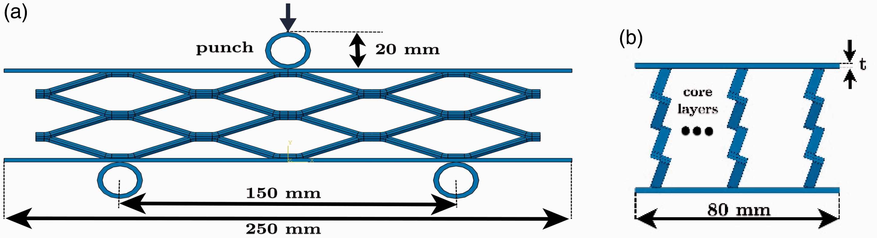
Geometry for simulation (a) front view and (b) side view.
Figure 2 schematically shows the slitting and expanding process of lattice sheets. The patterns in the expanded metal (latticed) absorber were demonstrated by two parameters. L2 denoted the lesser length, and L1 denoted the greater length (Figure 3). Expanded metal meshes were composed of cells that could be oriented in different ways as shown in Figure 4. Here, we studied this parameter at ϴ = 0, 45, and 90 angles. Table 1 shows the dimensions of the cells used herein.
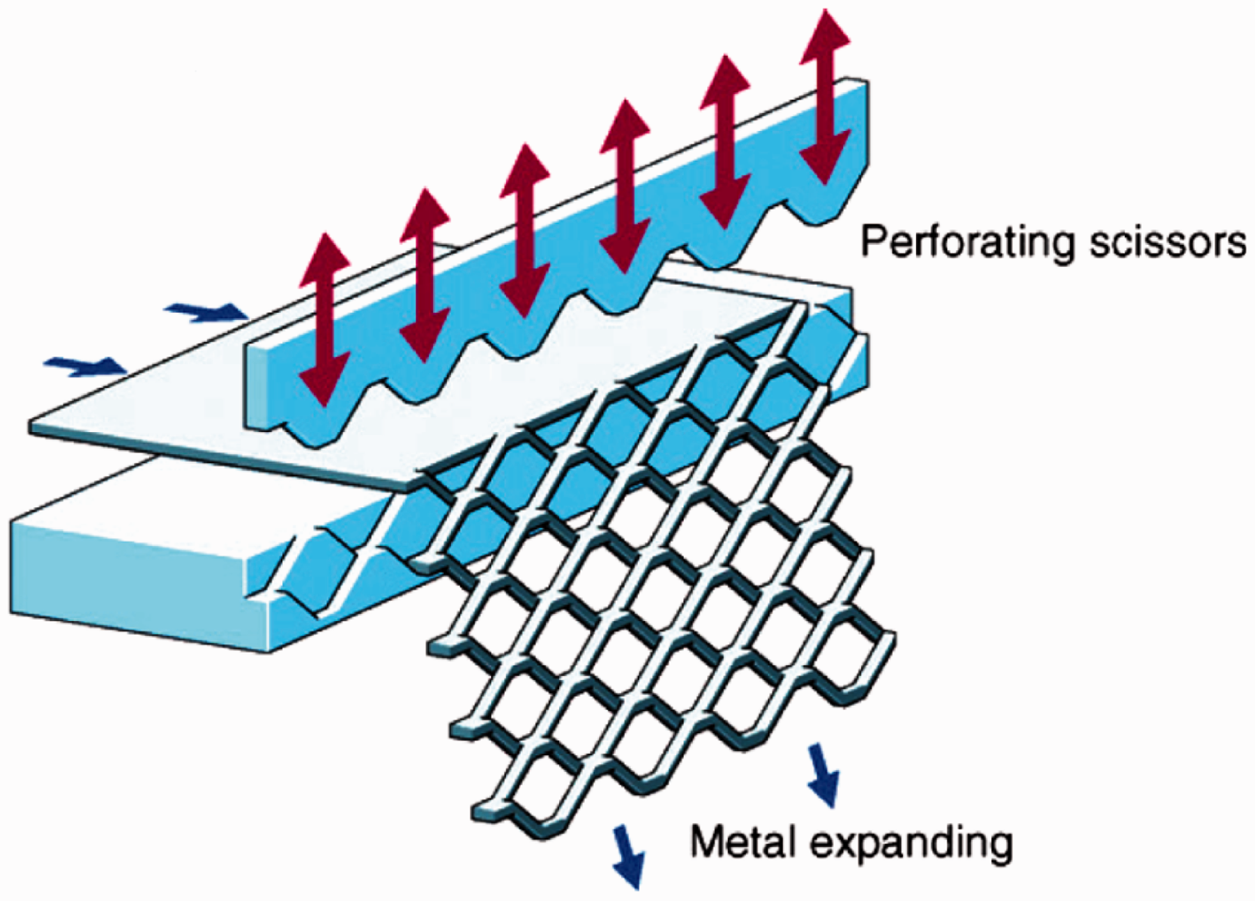
Schematic of the manufacturing process for the expanded metal sheets [22].
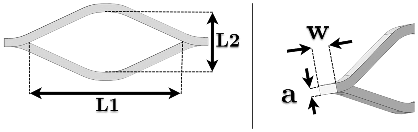
Definition of geometric parameters of an expanded metal sheet cell.
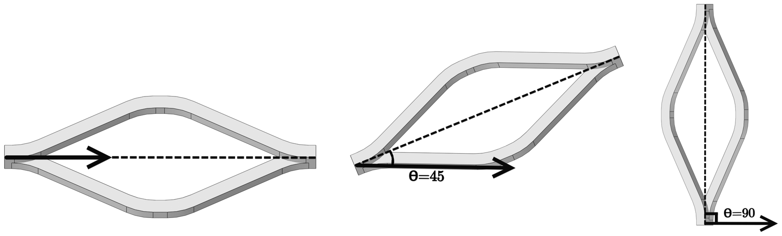
Orientations of the expanded metal cells.
Dimensions of the expanded metal cells.
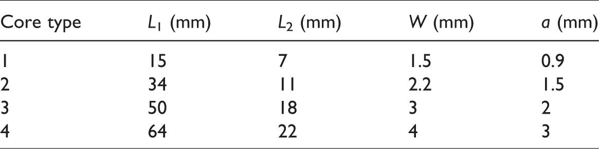
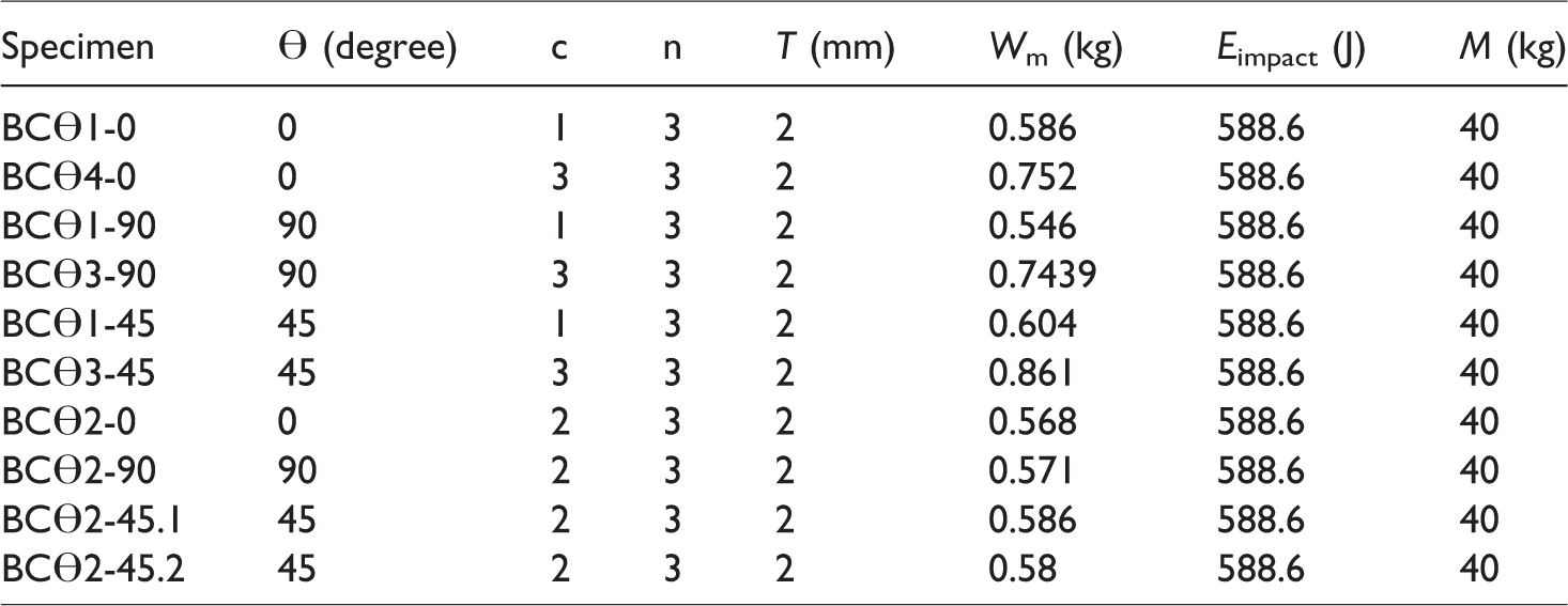
Figure 5 shows the sandwich beams with expanded metal sheets as core, which were designed for low-velocity impact test. Table 2 presents the measured dimensions of the test specimens. BCϴ indicates the model label in Table 2. Here, ϴ is the cell angle, c is the core type, n is the number of core layers, t is the substrate thickness, Wm is the mass of the models, M is the impact mass, and E is the impact energy.
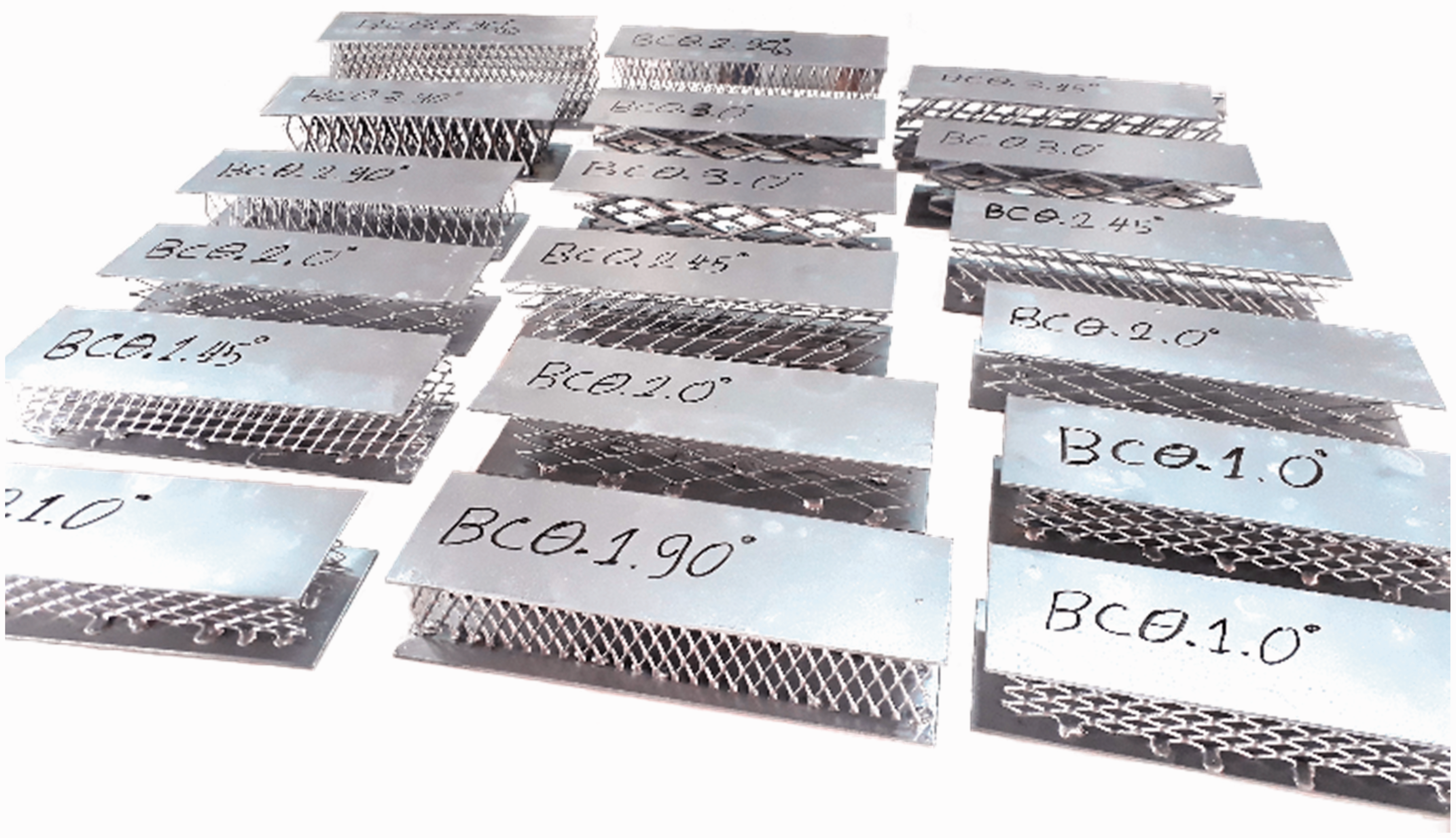
Specimens were made based on the parameters obtained from the DOE.
Computational design of the experiments.
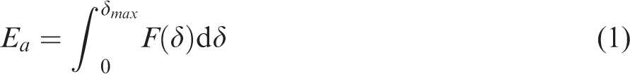
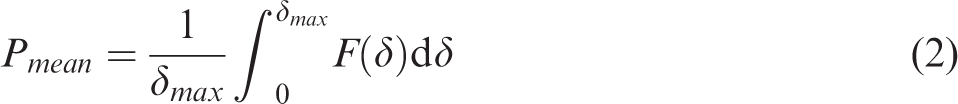
For calculating Ea capability, the initial peak force (Ppeak), mean force (Pmean), Ea, specific energy absorption (SEA), and CFE were selected as the design goals (Equations (1) to (4)). Energy absorbed per unit weight (SEA) is important in system design, where weight is the constraining factor. The amount of the absorbed energy is the area under the force–displacement curve. The crushing force efficiency is the ratio of the mean force to the initial peak force


Material properties
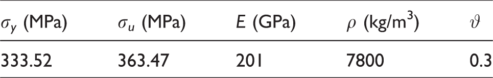
The expanded metal sheets were constructed using a cold-rolled ASTM A-611 steel [22]. The material characteristics were obtained from the standard tensile tests ASTM E08M-04 [23] on the specimens directly cut from the sheets. The tensile test curve is shown in Figure 6. Tensile tests were carried out in order to determine the mechanical properties of the cores and sheets as shown in Figure 7. The material properties are shown in Table 3.
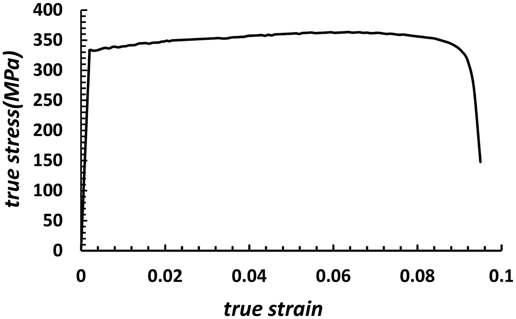
True stress–strain curves for steel (substrate and core).
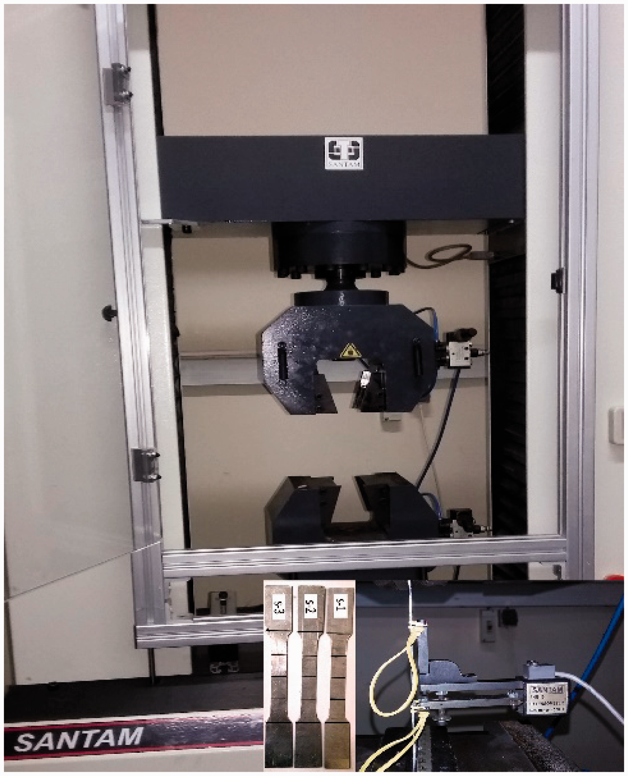
The tensile test setup with SANTAM machine.
Material properties.
Experimental setup
The low-velocity impact tests were conducted using the drop hammer impact machine [24] as shown in Figure 8. A 40 kg weight with the speed of 5.424 m/s fell freely causing the bending of the sandwich beam, and kinetic energy was released as a result of the free fall of the weight. The height of the fall of the weight for all the samples was constant and equal to 1.5 m. The low-velocity impact tests were carried out for the impact energies of 588.6 J. During the tests, the central deflection of the front face and the corresponding load on the structure was recorded by dynamic load cell. An accelerometer was mounted on the impact mass. The accelerometer was connected to a computer, which showed the acceleration–time diagram. For measuring the degree of displacement from the accelerometer data, we integrated twice [20].
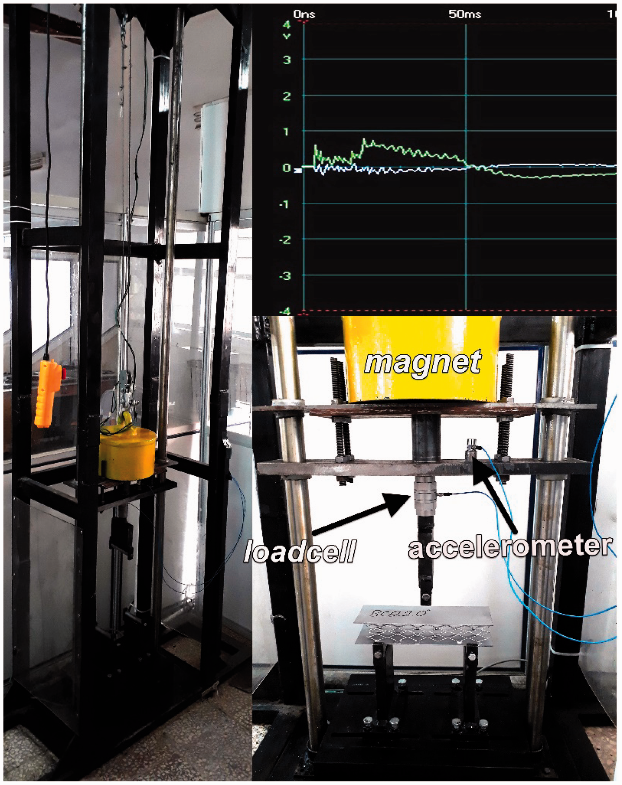
The experimental setup.
Numerical simulation
The profitable finite element software, ABAQUS, was used for the finite element simulation. As shown in Figure 9, due to the symmetry of the beam structures, except for the samples with cell orientation ϴ = 45 which were fully modeled, the rest of the samples were half-modeled to reduce the computational time. The substrate was meshed with C3D8I elements. The C3D8I element is the first-order fully integrated three-dimensional eight-node solid element, enhanced by incompatible modes to improve its bending behavior. The element used for modeling the lattice cores was S4R 4-node thick shell. Figure 10 shows a typical mesh of an expanded metal cell. The support and punch were modeled as rigid shells meshed with discrete rigid elements (element type R3D4).
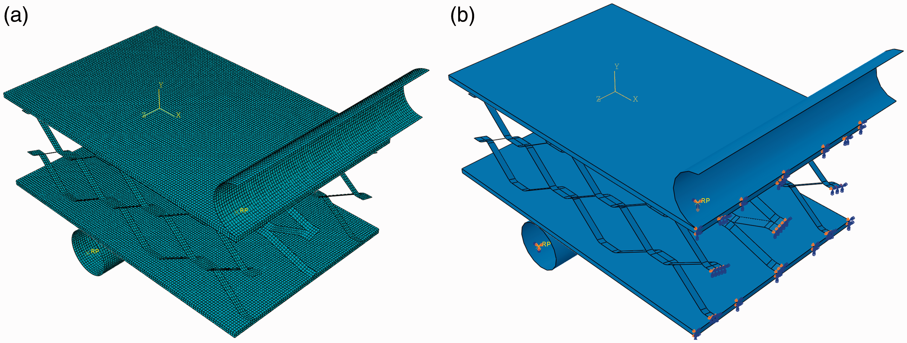
(a) FEM model and (b) boundary condition and loaded area.
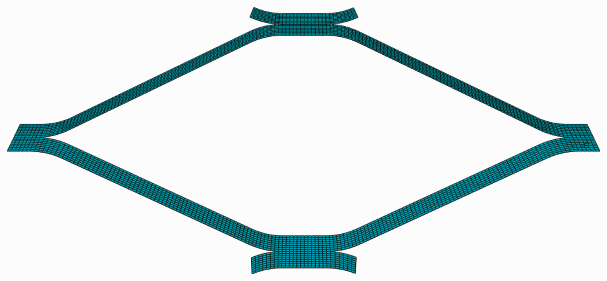
Mesh of an expanded metal cell.
Explicit dynamic analysis was used for simulation of the sandwich beams with lattice core. True stress against true plastic strain curves was used in the numerical simulation, which was converted from the engineering stress–strain curves obtained in the tensile tests. The punch had a single degree of freedom (DOF) in the direction normal to the plane of the top substrate, while all other DOFs of the punch were constrained.
For applying the friction between the constituents in the simulation, the penalty friction formulations were used. The contact interactions between the bottom substrate and rigid support, and between the top substrate and punch were modeled as the “surface-to-surface” contact was defined with the friction coefficient of 0.25 [25–28]. A “self-contact” interface was also selected to simulate the collapse of the specimens when the elements of the lattice core contacted each other.
To study the mesh sensitivity, three cases of different mesh sizes were analyzed for the model of a sandwich beam. For the elastic deformation, the curves from the three cases were almost the same. Cases 2 and 3 demonstrated similar results, indicating that the mesh size of 1 mm was sufficiently optimal. The simulation results in terms of force–displacement curves are compared in Figure 11.
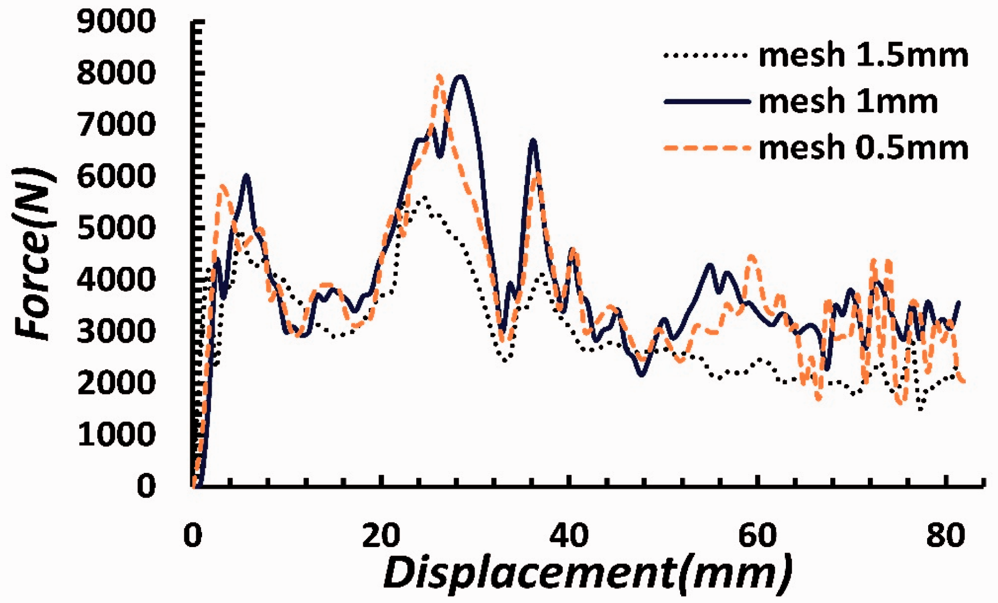
Validation of mesh size for finite element simulation.
Results and discussion
Results showed that force–displacement curves achieved by numerical simulations were in good agreement with those obtained from the experimental tests. Disagreement between the simulation and experimental results can be attributed to the fact that our simulation model did not clarify the effects of initial material imperfections in the core layers and imperfect connection between the sandwich beam components.
In the low-velocity impact tests, it is observed that the welds joining the substrates to the core layers, as well as those joining the core layers to one another, were in general weaker than the rest of the structure, and the debonding occurred in a few cases. The performed tests and force–displacement curves of the models are shown in Figures 12 to 15. The experimental load–deflection behavior of each core arrangement was compared with the finite element results in Figure 16. Energy–displacement curves for the sandwich beams with different cores are shown in Figure 16.
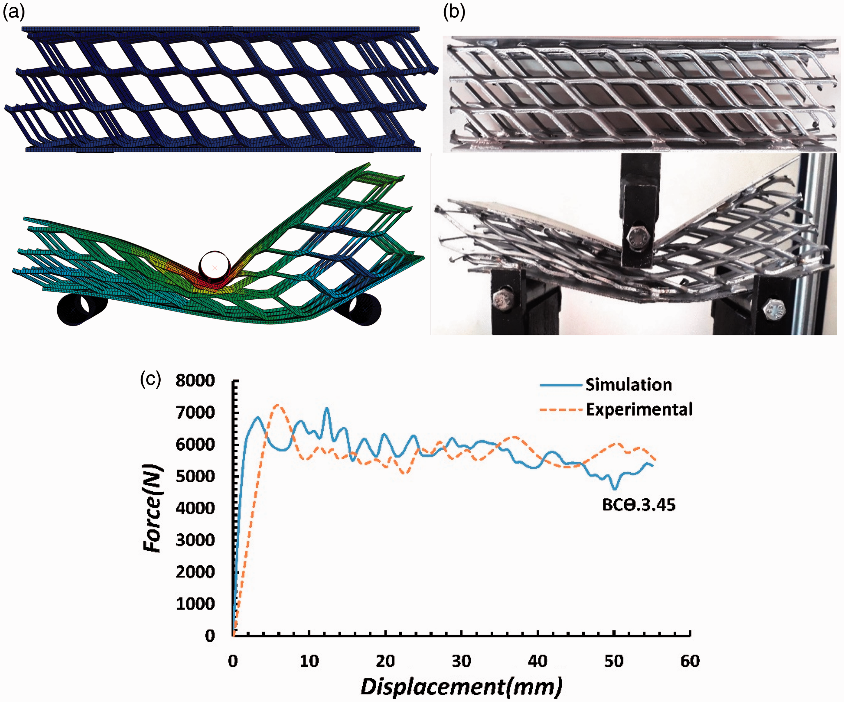
Comparison of the experiments and FEA predications for the mechanical response of the sandwich beams with lattice core bending deformation. (a) The corresponding simulated FEA results, (b) the experimentally deformed specimens, and (c) the force–displacement curves for BCϴ3-45.
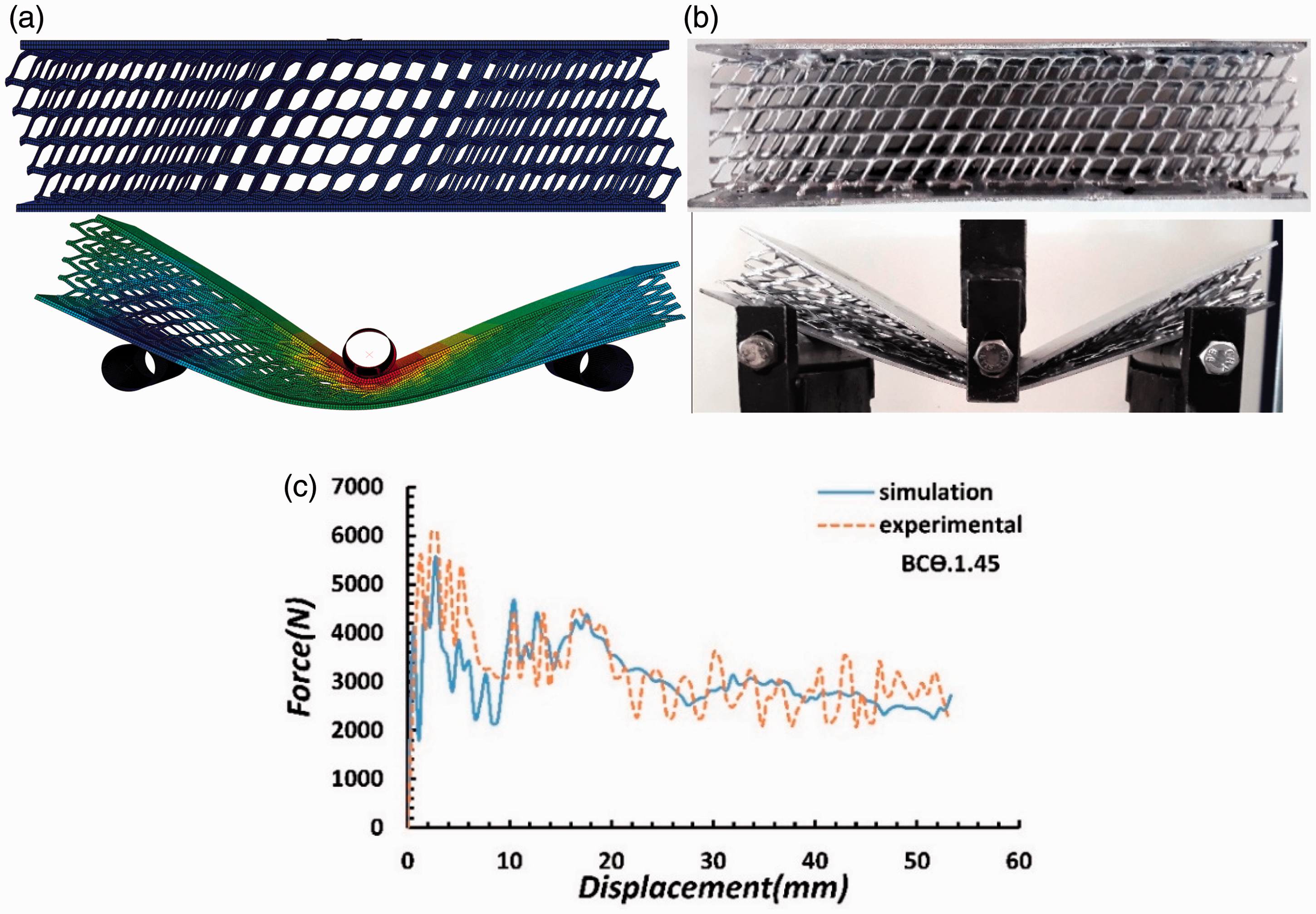
Comparison of the experiments and FEA predications for the mechanical response of the sandwich beams with lattice core bending deformation. (a) The corresponding simulated FEA results, (b) the experimentally deformed specimens, and (c) the force–displacement curves for BCϴ1-45.
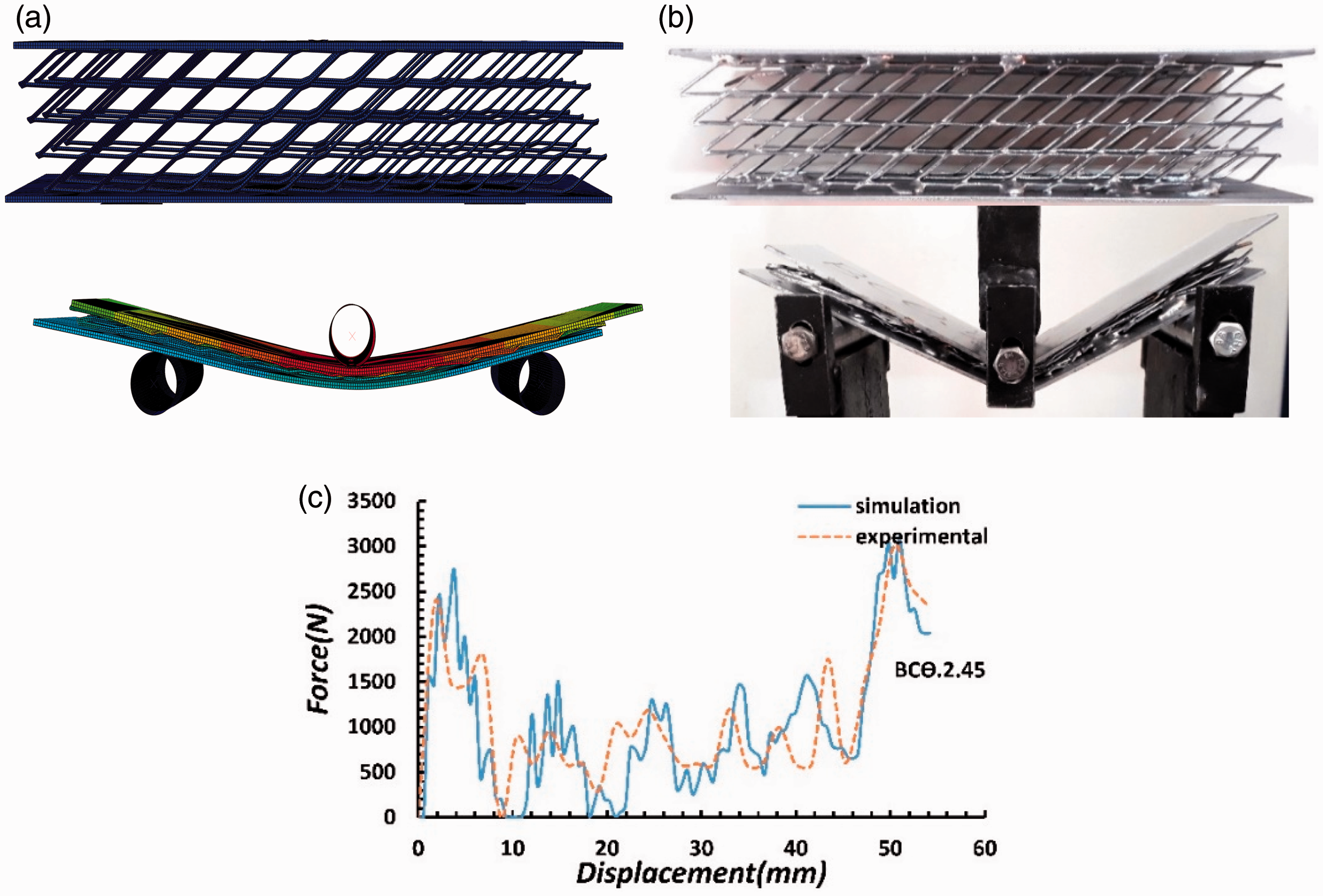
Comparison of the experiments and FEA predications for the mechanical response of the sandwich beams with lattice core bending deformation. (a) The corresponding simulated FEA results, (b) the experimentally deformed specimens, and (c) the force–displacement curves for BCϴ2-45.
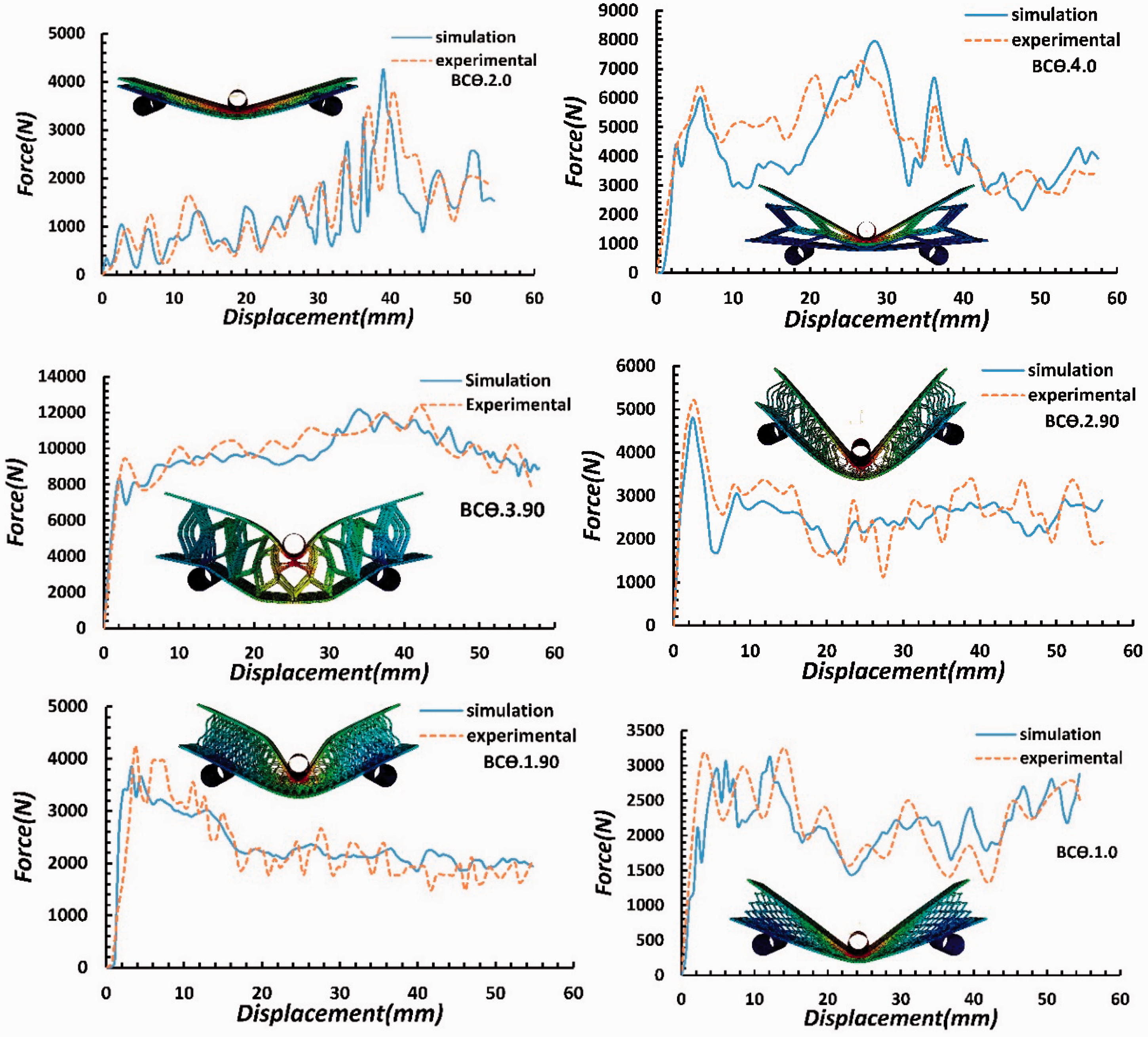
Comparison of the experiments and FEA predictions of the force–displacement curves for all the sandwich beams.
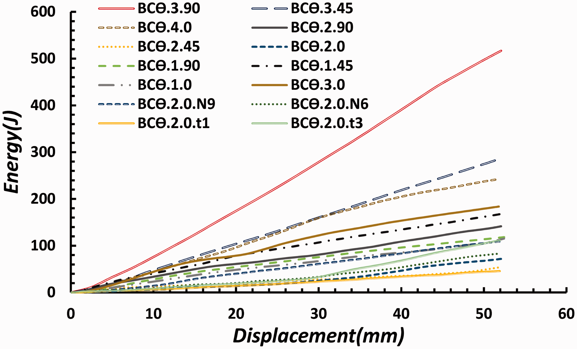
The energy–displacement curve for all the sandwich beams obtained from the simulation result.
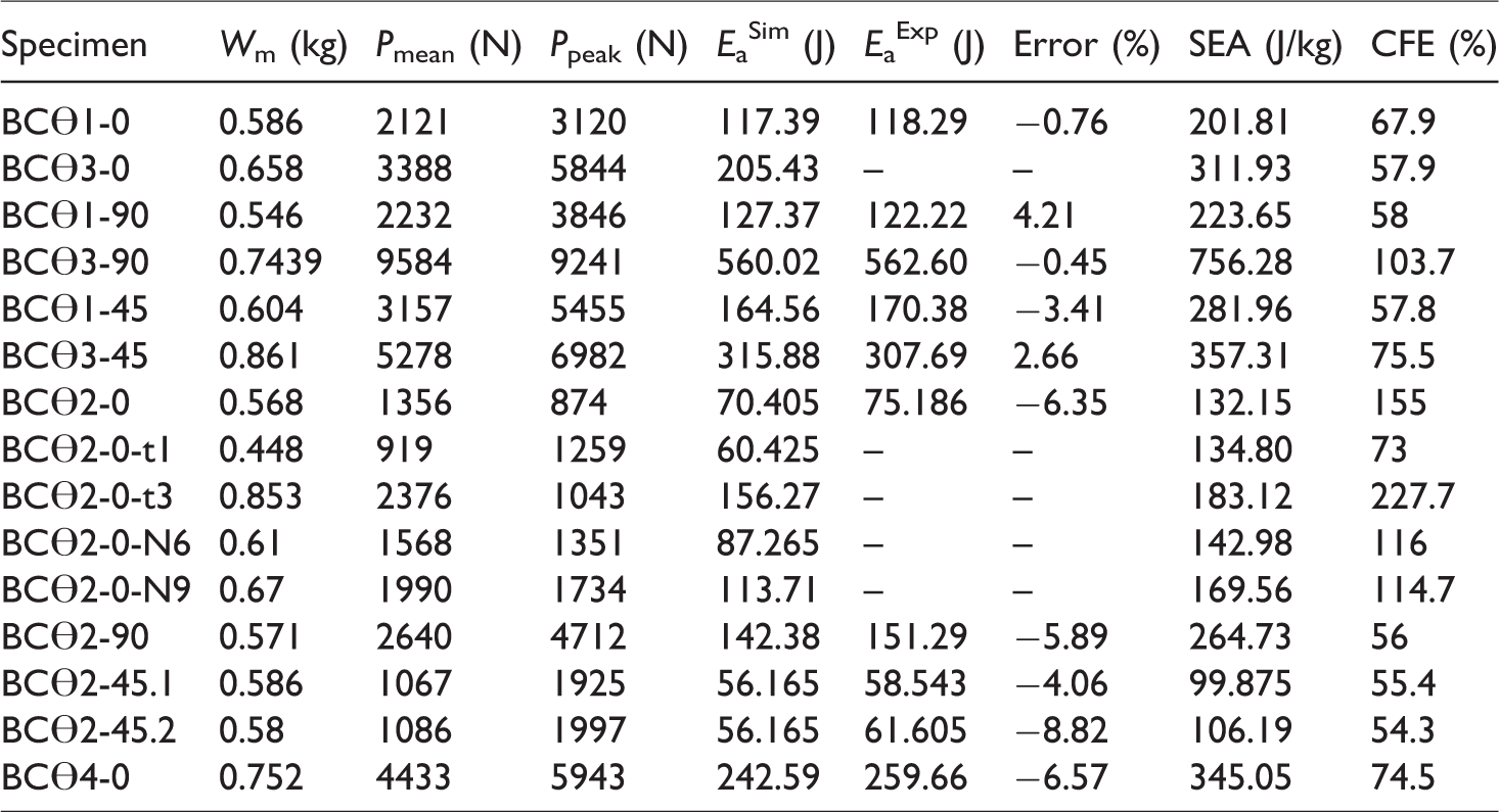
Their force–displacement curves had relatively regular oscillations considering the type of the core. The data obtained from the curves showed that the peak force was suitable and close to the mean force, as was also revealed by the calculated Ea. The Ea capacities were calculated for all the models. The absorbed energy obtained numerically and experimentally was then compared (Table 4). To calculate the initial peak force, a similar filtering was used in the force–displacement curves for all the samples, as shown in Figure 17.
Experimental and numerical results of the specimens.
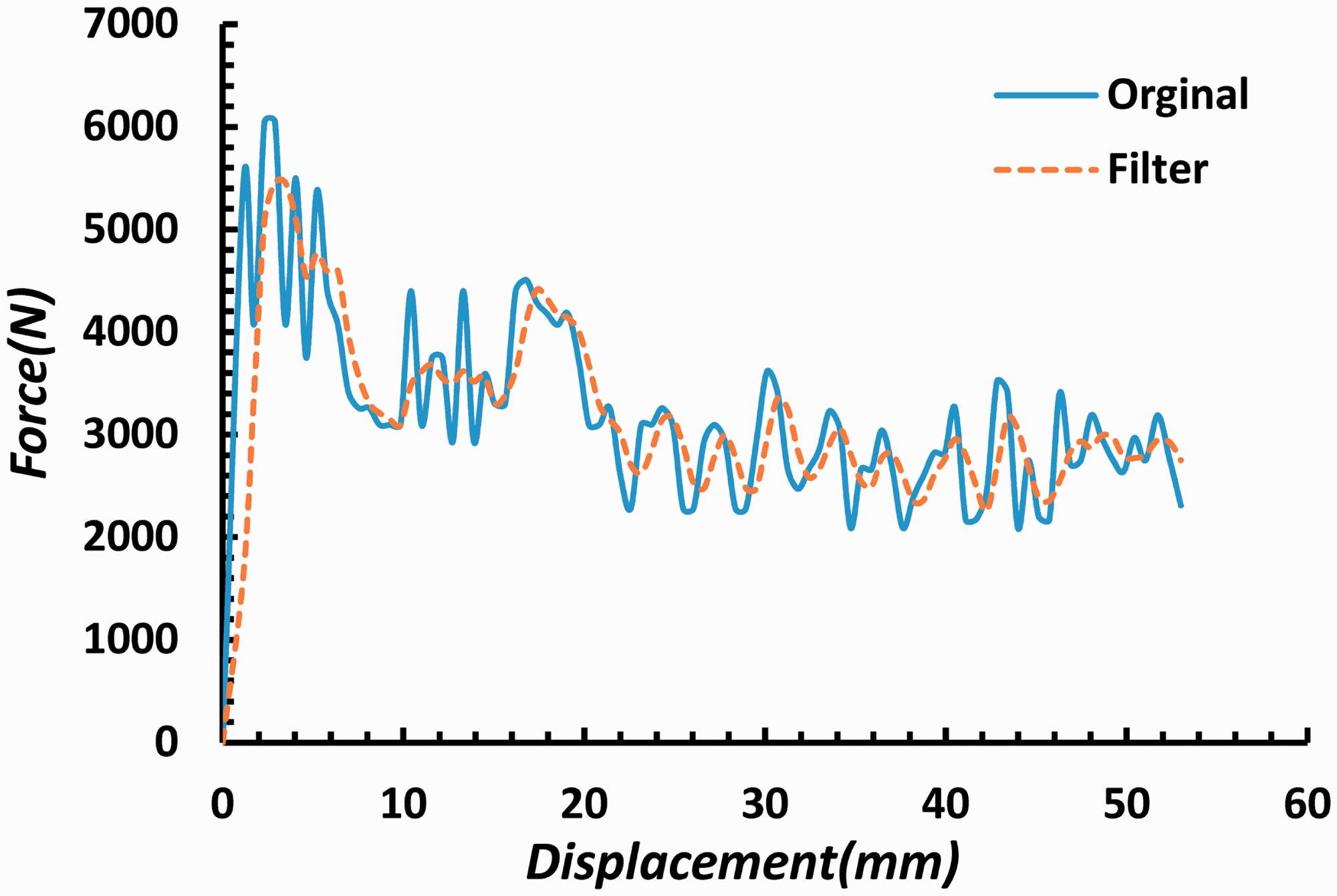
The filtered force–displacement diagram for determining the initial peak force.
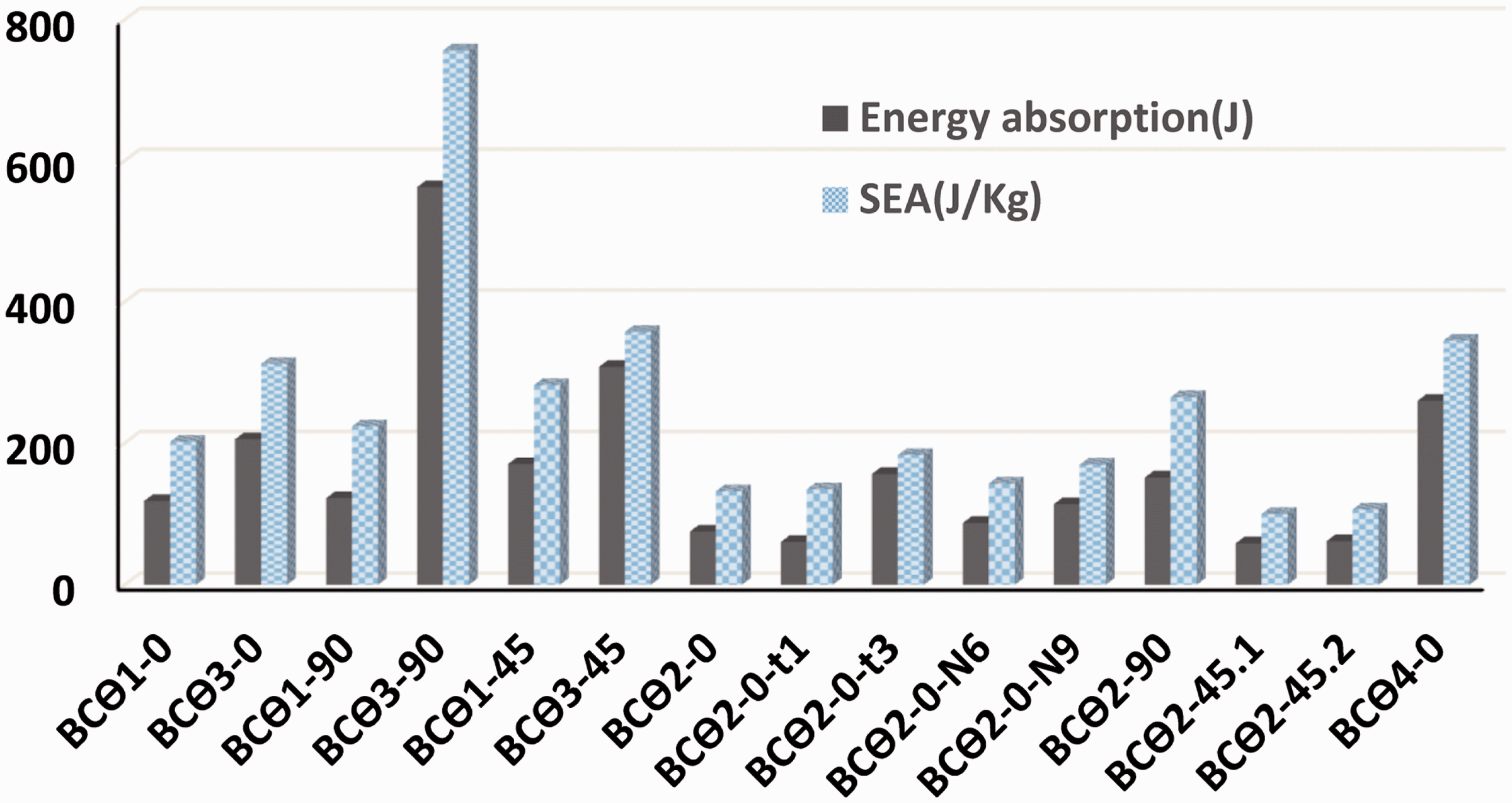
The Ea capacity of all the tested beams at a same deflection was evaluated by the Ea and SEA, as illustrated in Figure 18. It is clear from this figure that the sandwich specimen of BCϴ3-90 had the highest SEA equal to 756.282 J/kg.
Comparison of the total energy absorbed and SEA between the specimens.
For the specimens studied in this research work, all the specimens displayed good progressive deformation. From this figure, it can be seen that the least value of the absorbed energy in those specimens was 58.543 J belonging to BCϴ2-45.1 with a decrease between 3.11% and 89.59% with respect to the sandwich specimens. The largest value of the absorbed energy was 562.603 J belonging to the sandwich specimen BCϴ3-90, which was 89.59% greater than that of BCϴ2-45.1.
For the sandwich beams with lattice core, energy absorption was calculated from both the experimental and FE simulation. The contribution of each specimen to the energy absorption is given in Figure 19.
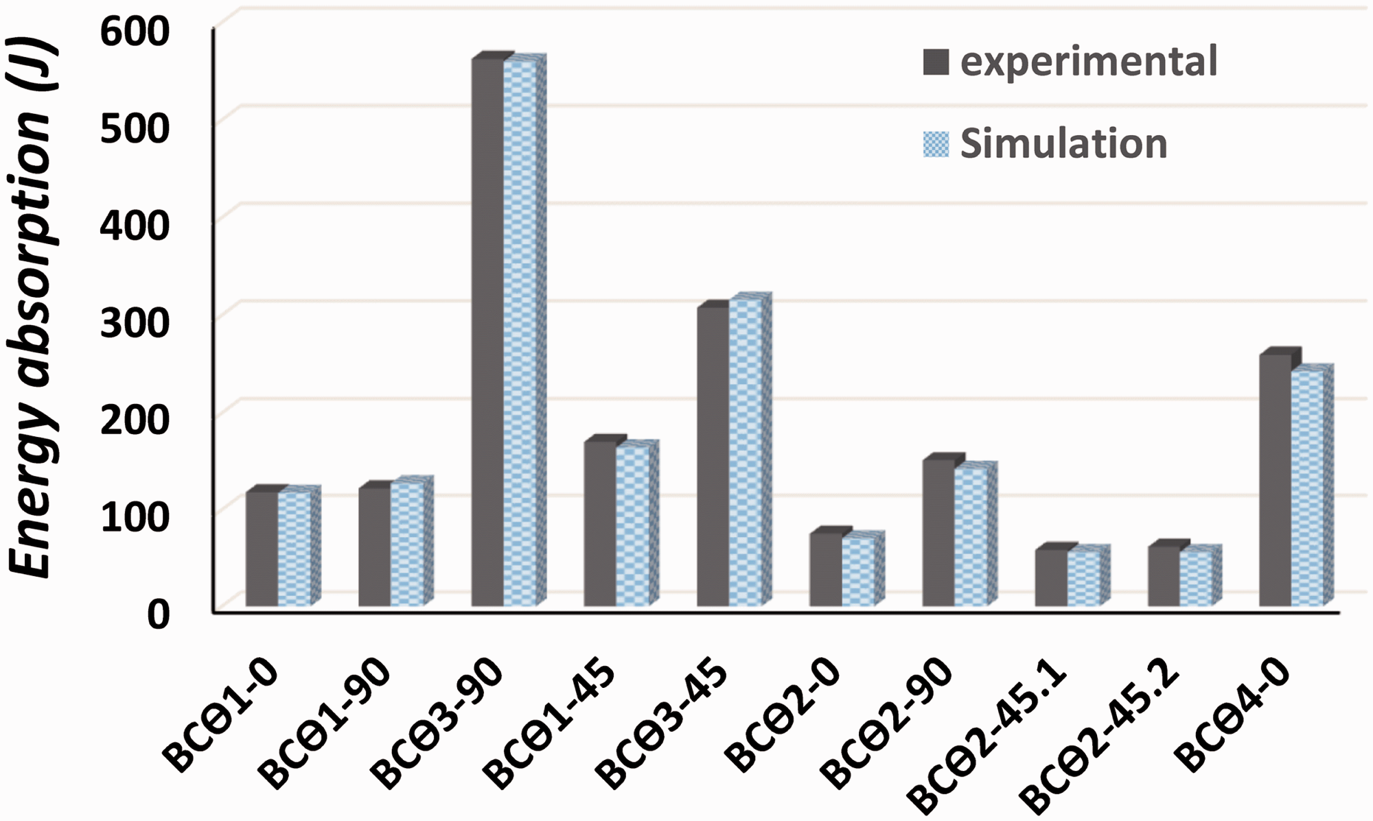
Energy absorption for the sandwich beams from the FE simulation and experimental test.
Experimental tests require time and money, and therefore, can be replaced by numerical simulations. Results showed that energy absorption values obtained by the numerical simulations were in good agreement with those obtained from the experimental tests. As can be seen, and also as already mentioned, the values were to some extent consistent with each other; however, errors were observed in some cases.
Figure 20 shows the experimental results for the crush force efficiency. As is evident from this figure, the least value of the crush force efficiency was 54.3%, which belonged to the specimen BCϴ2-45.2. However, the largest value of the crush force efficiency in the experimental specimens was 227.7% belonging to the specimen BCϴ2-0-t3. This is due the fact that the peak load was smaller than the mean crush load in those specimens. Comparing the peak loads, the highest values corresponded to the sandwich beam with a core of type 3 and angle of 90.
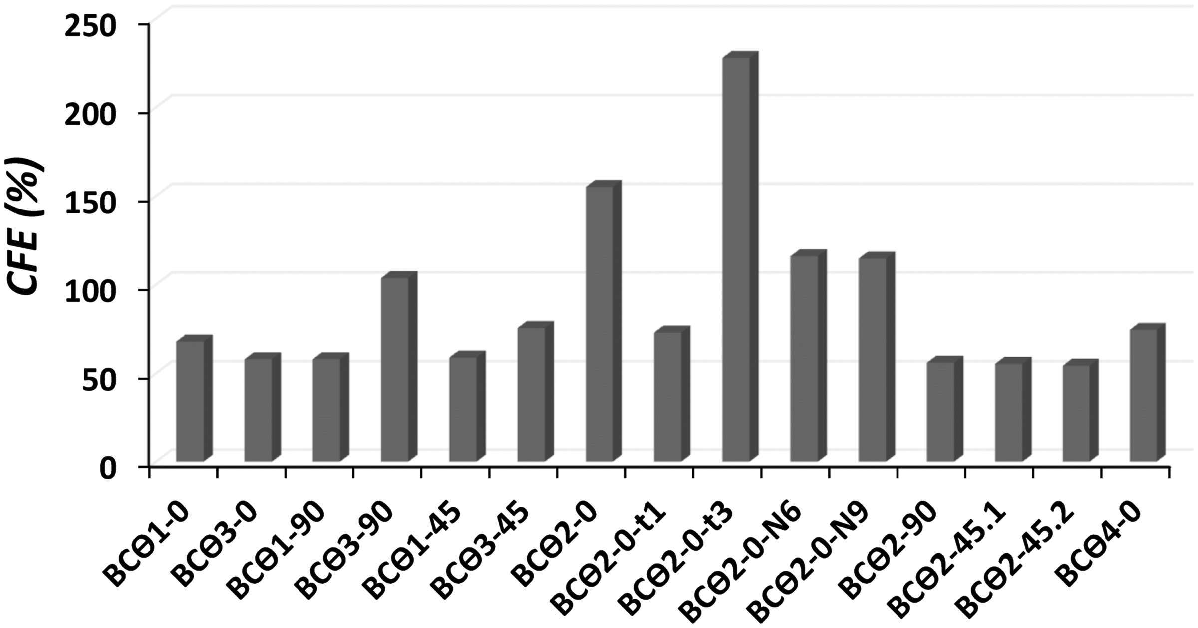
Comparison of the crush force efficiency between the specimens.
The effect of the substrate thickness on the impact behavior of the sandwich beams
Figure 21 shows the effect of the substrate thickness on the impact behavior of the sandwich beams for energy absorption on the specimen BCϴ2-0 with three different thicknesses. The specimen with a face sheet thickness of 1 mm (BCϴ2-0-t1) had the minimum energy absorption of 60.42 J, whereas the specimen with the substrate thickness of 3 mm (BCϴ2-0-t3) had the maximum energy absorption of 156.27 J. These results showed that increasing the thickness by up to three times increased the energy absorption by 61.33%. The specimens having a face sheet thickness of 3 mm exhibited a better plastic dissipation of the impact energy. The experiments showed that the sandwich beam with thicker substrates had a more homogeneous collapsed in the longitudinal direction of the beam.
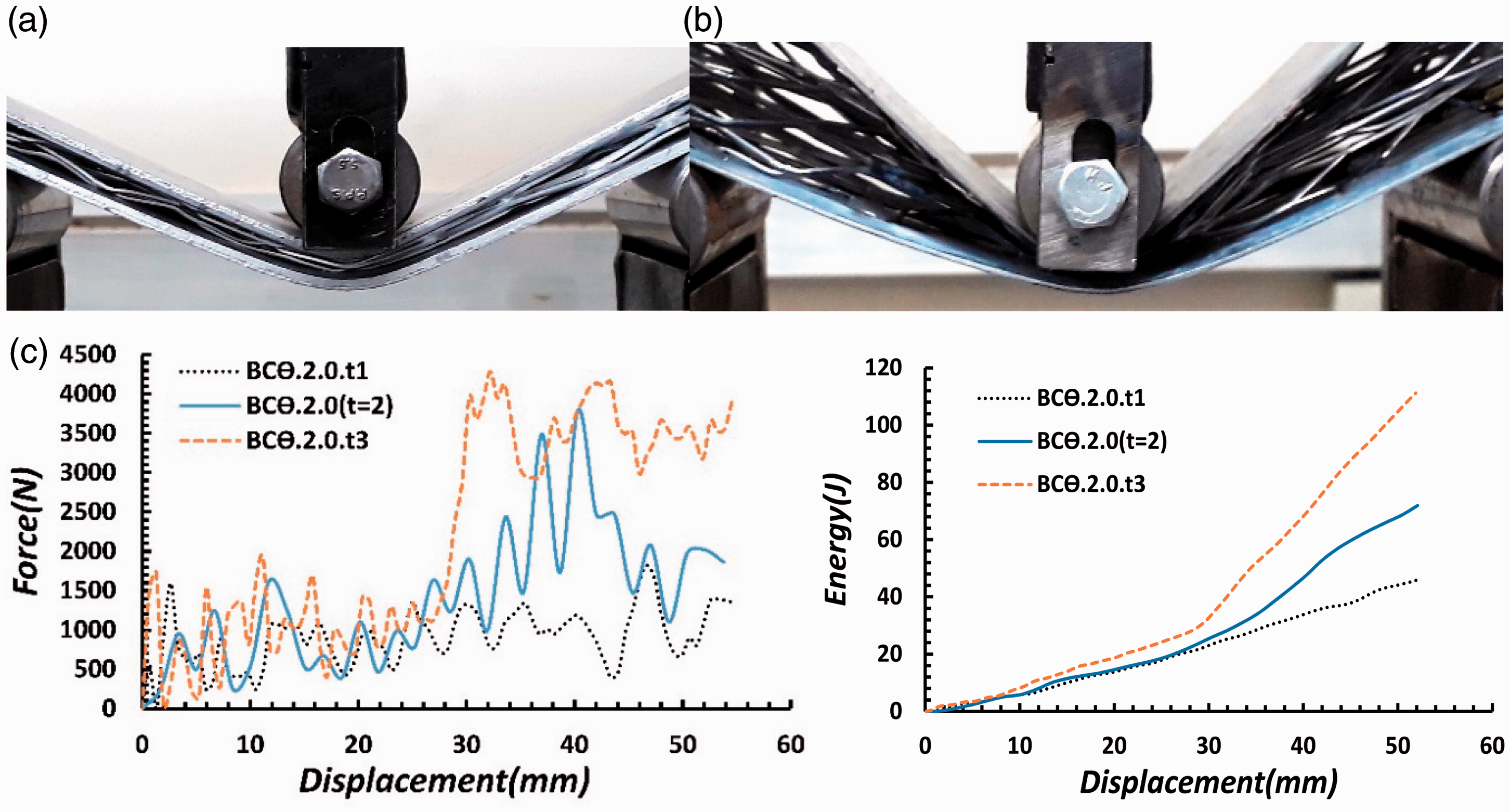
The effect of (a) the 3-mm substrate thickness, (b) 1-mm substrate thickness, on the after-impact thickness variation of the central impact region and (c) force–displacement and energy–displacement curves.
The CFE reached 73% for the sandwich beams having the substrate thickness of 1 mm while the SEA was 134.8 J/kg, whereas the CFE reached 227.79% for the specimens with a substrate thickness of 3 mm while the SEA was 183.12 J/kg. However, the specimens having a thicker face sheet exhibited a uniform increase in the CFE and SEA.
The effect of the core size on the impact behavior of the sandwich beams
Figure 22 shows the deformation of a sandwich beam with lattice core under low-velocity impact loading. Force– and energy–displacement curves for the sandwich beam with different cores are shown in Figure 23. As can be observed, the permanent deflections decreased as the core size increased. The stiffer core contributed to the bending stiffness of the face sheets. The specimens with the core type of 4 (BCϴ4-0) can absorb more impact energy than the other specimens with lower size cores in the same deflection. The total impact energy was spent on the elastic and plastic deformations of both the substrate and lattice core, but was mostly absorbed by the lattice core.
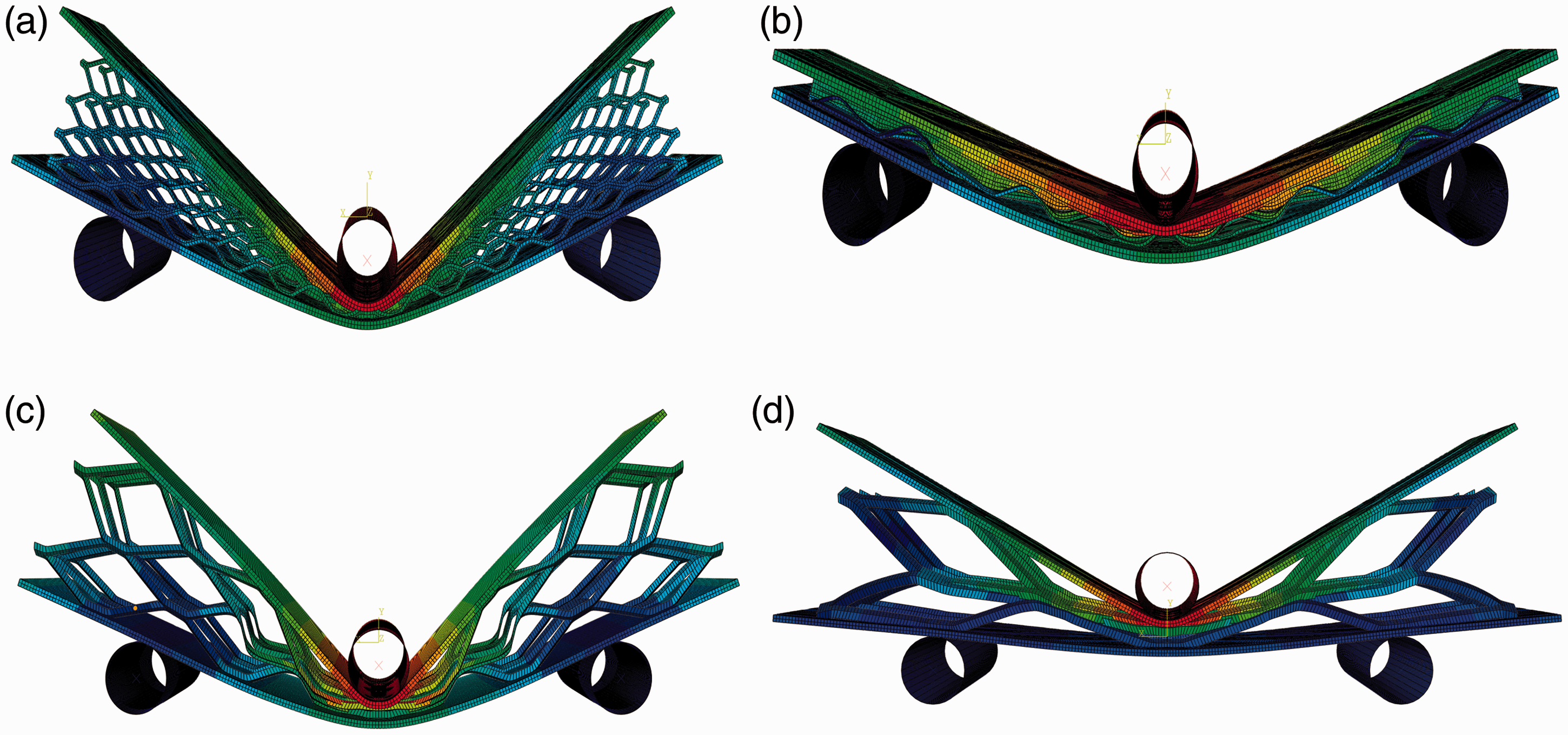
Collapse of the models with (a) core type = 1, (b) core type = 2, (c) core type = 3, and (d) core type = 4.
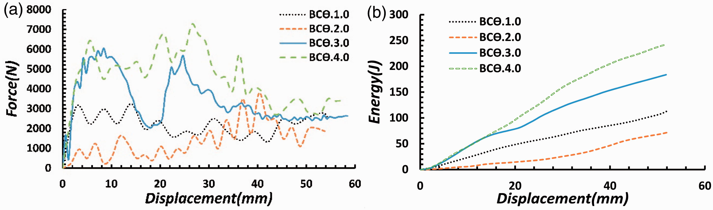
(a) Load–displacement response and (b) energy–displacement curve for the sandwich beam with four different cores.
From this figure, it can be seen that the least value of the absorbed energy in those specimens was 75.186 J belonging to BCϴ2-0 with a decrease between 36.44% and 71% with respect to the sandwich specimens. The largest value of the absorbed energy was 259.66 J belonging to the sandwich specimen BCϴ4-0, which was 71% greater than that of BCϴ2-0. It is clear from Figure 24 that the specimen with the core type of 2 (BCϴ2-0) had the minimum SEA of 132.15 J/kg, whereas the specimen with the core type of 4 (BCϴ4-0) had the maximum SEA of 345 J/kg. These results showed that increasing the cell size from type 2 to type 4 increased the SEA by 61.7% and also increased the specimen weight by 24.39%.
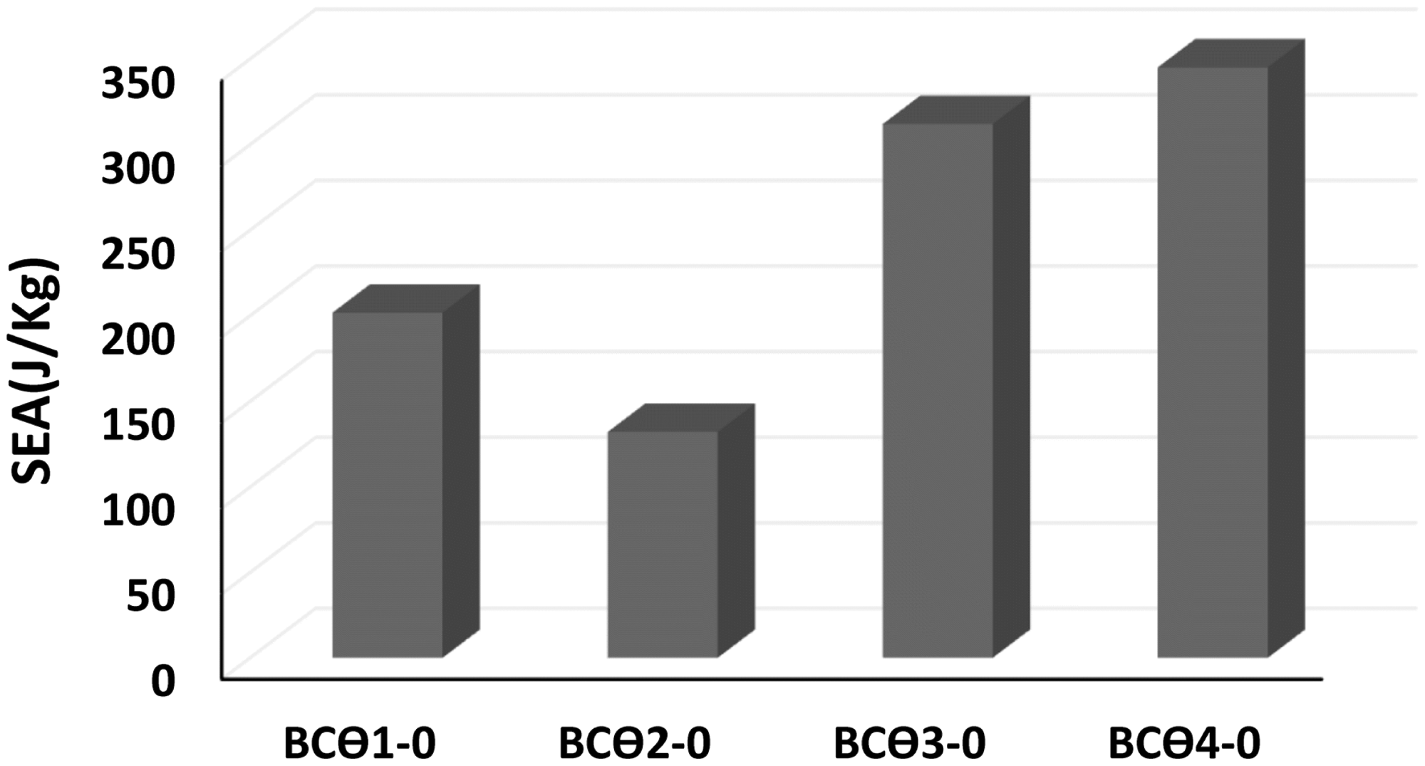
Specific energy absorption between the specimens with different core sizes.
The effect of the core layer number on the impact behavior of the sandwich beams
Figure 25 shows the effect of the core layer number on the impact behavior of the sandwich beams for energy absorption on the specimen BCϴ2-0 with three different core layer numbers. The specimen with three layers (BCϴ2-0(n = 3)) had the minimum energy absorption of 75.186 J, whereas the specimen with nine layers (BCϴ2-0-N9) had the maximum energy absorption of 113.71 J. These results showed that increasing the core layers by up to three times increased the energy absorption by 33.88%.
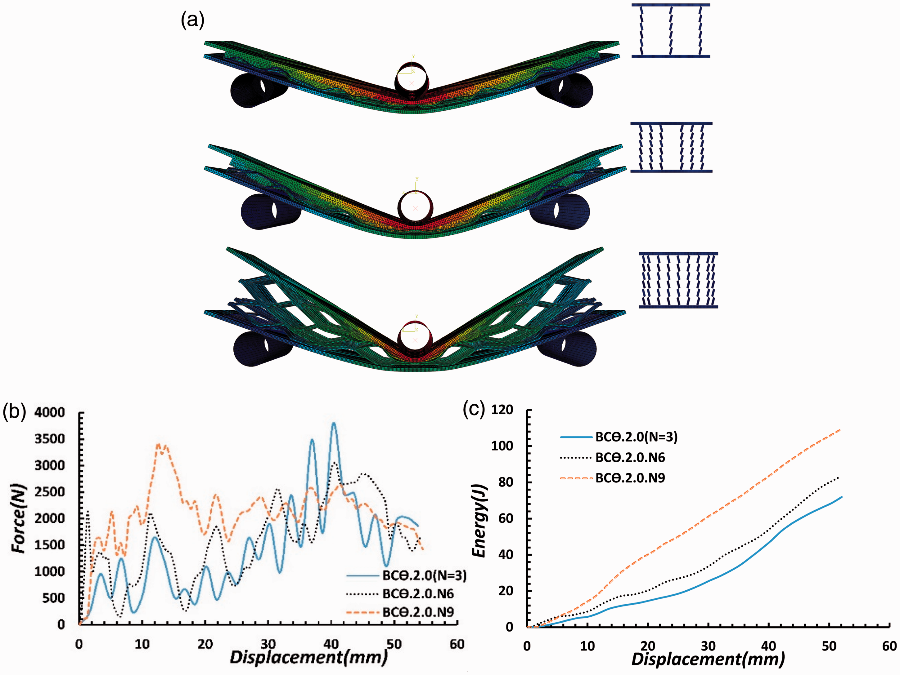
(a) Collapse of the models with variable number of core layers, (b) force–displacement diagrams, and (c) energy–displacement diagrams.
It is clear from Figure 26 that the specimen with three layers in core (BCϴ2-0(n = 3)) had the minimum SEA of 132.15 J/kg, whereas the specimen with nine layers in core (BCϴ2-0-N9) had the maximum SEA of 169.56 J/kg. These results indicated that increasing the layer number by up to three times increased the SEA by 22% and also increased the specimen weight by 15.1%.
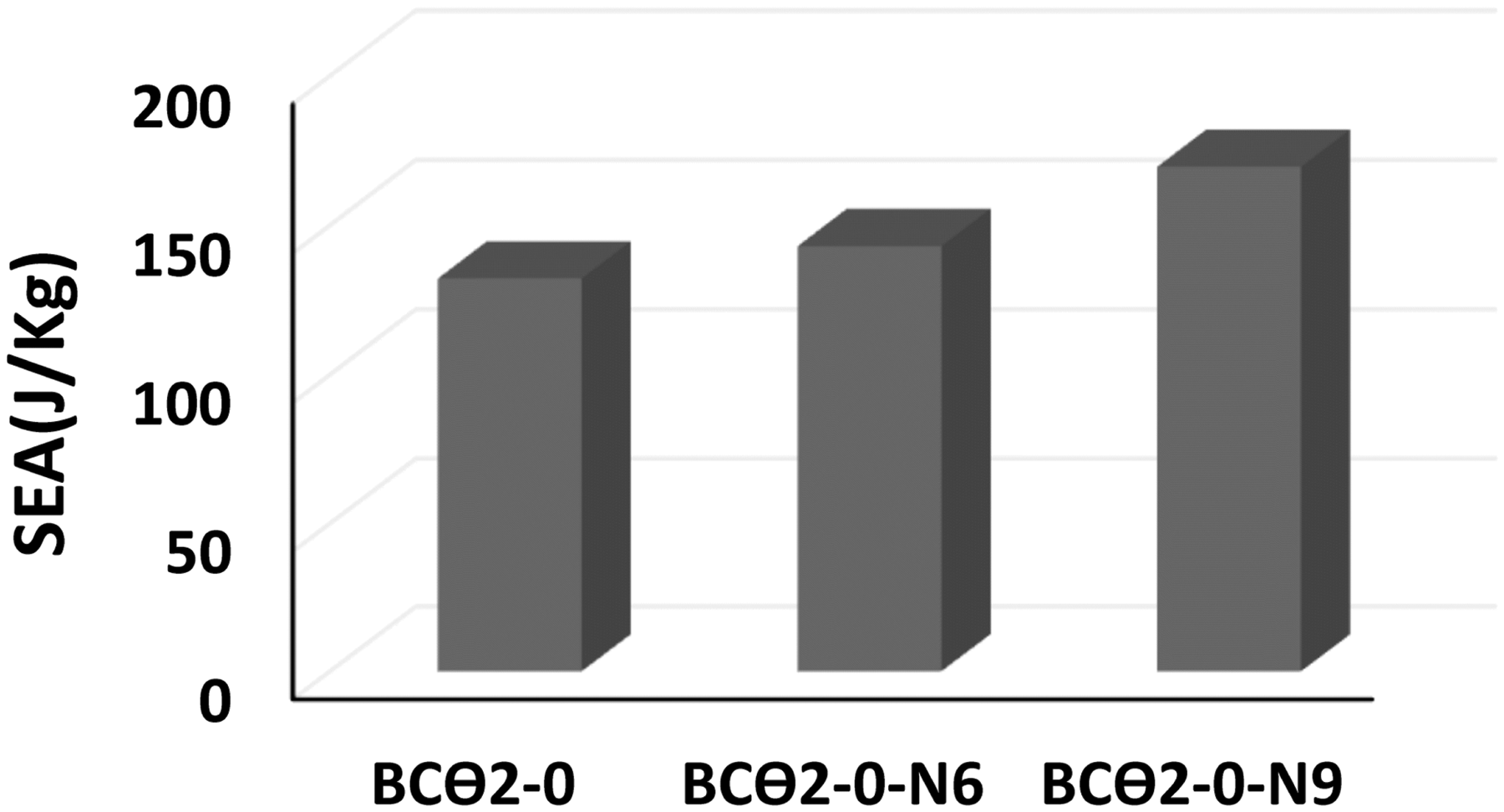
Specific energy absorption between the specimens with different core layer numbers.
The effect of the cell orientation on the impact behavior of the sandwich beams
The effect of the cell orientation increasing the type of cells from 1 to 3, when keeping the number of the layers equal to 3 is shown in Figure 27. In a more pronounced manner, the collapse modes changed with changing the angle of the cells. The specimens having a core type of c = 3 could absorb more impact energy than the other specimens having lower size in all cell orientations. As the cell angle increased, the SEA and CFE similarly increased.
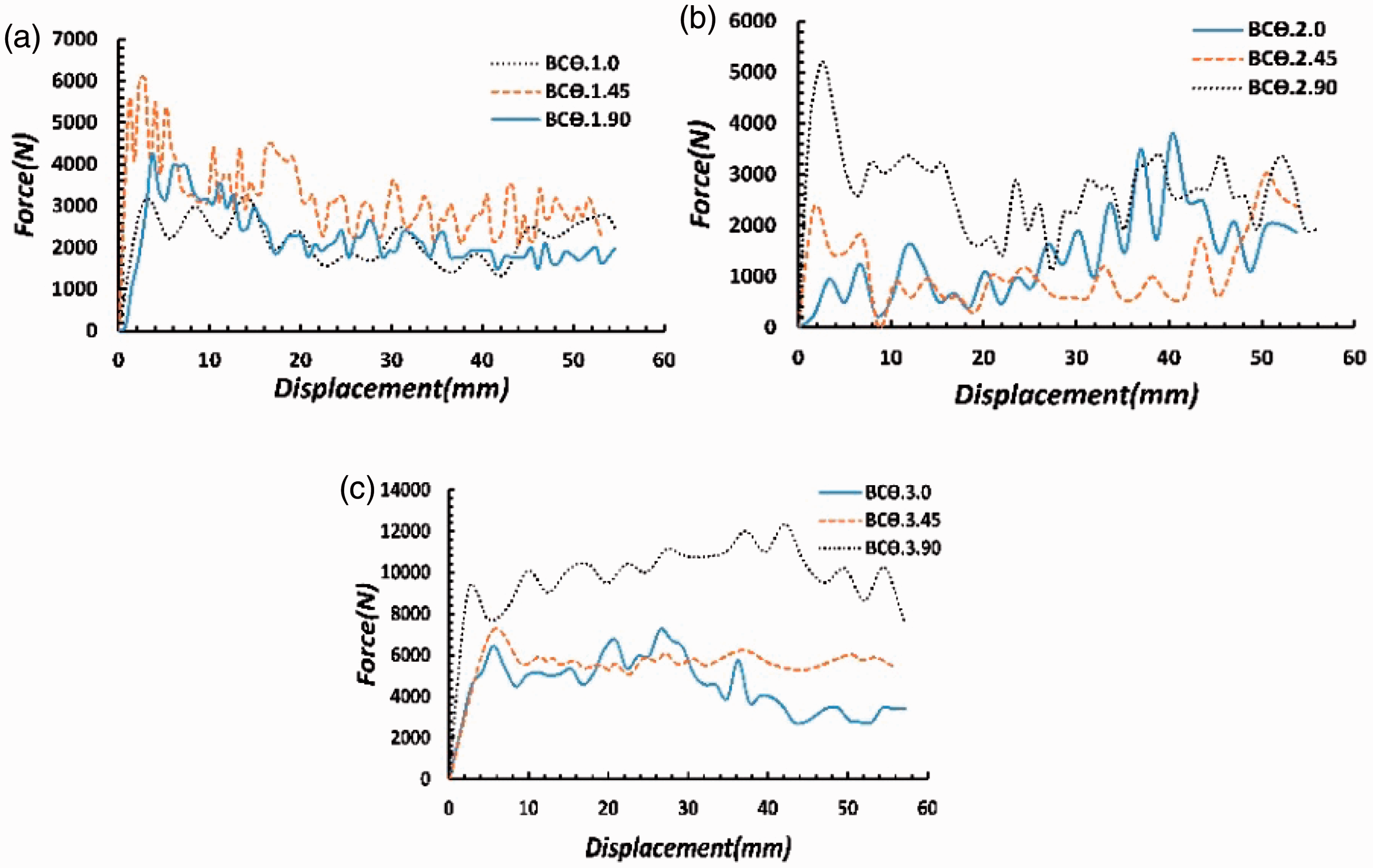
Collapse of the models with different cell angles for (a) c = 1, (b) c = 2, (c) c = 3 and the force–displacement diagrams.
As shown in Figure 28, the specimens having a core type of c = 2 had the lowest SEA. In this type of core, the lowest SEA occurred at ϴ = 45, which was 62.27% less than ϴ = 90. Moreover, this type of core with ϴ = 0 had the highest CFE value with 155% among all the samples. The SEA reached 201.81, 281.96, and 223.65 J/kg for the sandwich beam specimens having a core type of c = 1 for the cell angles of ϴ = 0, 45, and 90, respectively. The force–displacement curves of the sandwich beams within lattice core with different cell angles are shown in Figure 27.
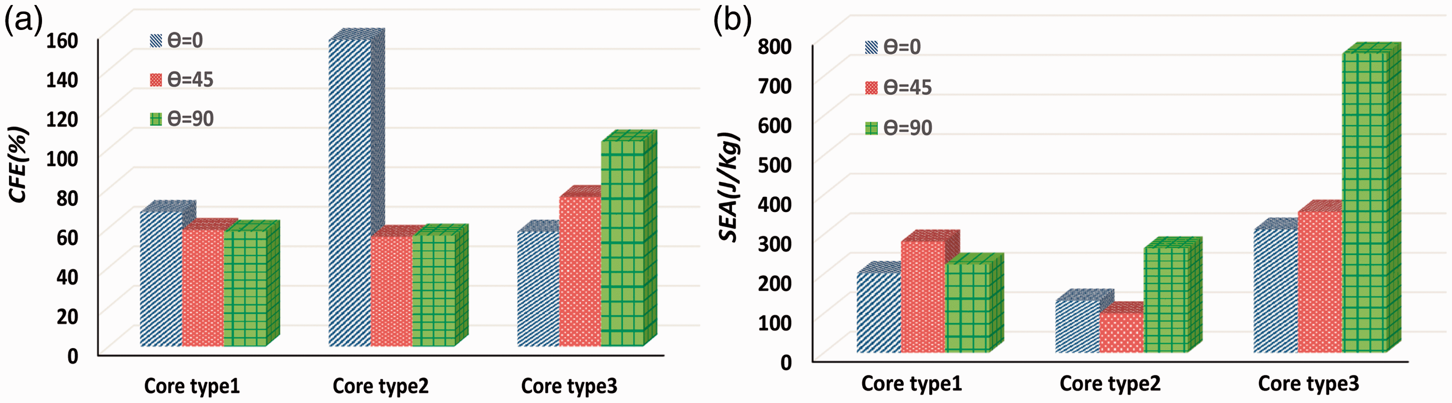
Comparison of (a) crush force efficiency and (b) specific energy absorption between the specimens with different cell angles.
Conclusions
In this study, the low-velocity impact behavior of the sandwich beams with expanded metal sheets as core by the drop hammer free fall setup was investigated experimentally for different core sizes, substrate thickness, core layer number, and cell orientation. The relationship between the force and displacement at the middle point of the sandwich beam was obtained from the experiments. Moreover, bending collapse mechanisms for the beams with different cores were analyzed. Sandwich beams with expanded metal sheets as core are lightweight; however, they have high energy absorption capacity and thus, can be used as good absorbers. The behavior of the sandwich beam lattice core is a function of the orientation and size of cells.
Simulation was performed using ABAQUS. The results of the experimental tests and numerical simulations as well as the collapse shapes of the models showed that the sandwich beam with lattice cores could be used as energy absorbers in the industry.
In the present research, for the first time, when these sandwich beams were subjected to low-velocity bending impact, it was found that contrary to their low weight, the sandwich beams can absorb the clash energy due to their mesh and multiple joints and nodes in core. The major conclusions are summarized as follows:
The effects of cell size and cell orientation in the energy absorption were coupled with each other. For example, in the core of type 3, the increase in the angle led to an increase in the energy absorption, whereas in the core of type 2, such behavior was not observed. Increasing the cell orientation in a reasonable range is required to improve the performance of the structure under bending collapse. The results of the tests showed that the increase in the core layers up to three times increased the SEA by 22%. The results demonstrated that increasing the substrate thickness by up to three times increased the SEA by 26.38%. Expanded metal sheets had a symmetric collapse mechanism due to their structure. This resulted in a good order force–displacement curve. The peak force was low and close to the average force and it was even lower in some cases. The calculation of the crushing force efficiency also indicated this matter. The calculated crushing force efficiency showed that the sandwich beam with lattice core had a high efficiency of energy absorption. Comparing the numerical and experimental results revealed a good agreement between them. Sandwich beams with expanded metal sheets as core can be used in industry as a modern absorber. This is because despite their very low weight, such beams can endure symmetric collapse under impact loadings and crush to their ends.
Footnotes
Declaration of Conflicting Interests
The author(s) declared no potential conflicts of interest with respect to the research, authorship, and/or publication of this article.
Funding
The author(s) received no financial support for the research, authorship, and/or publication of this article.