
Abstract
In this study, the failure behaviour of lattice sandwich panels under three-point loading has been studied using a nonlinear finite element analysis. The failure mechanisms of lattice-cored sandwich panels can be classified in three modes; facesheet yielding, facesheet wrinkling and core shear. When the panel fails due to facesheet yielding or core shear, the evaluation of the strength of the lattice-cored panel can be undertaken in the same manner as that of a foam-cored panel. In contrast, when wrinkle-like deformation occurs in the facesheets, the failure load can be estimated from the buckling stress of the facesheet. The failure mode map for the lattice-cored panel with the coordinate system tf /l and
Introduction
Sandwich beams and panels composed of a porous foam core and stiff facesheets have been employed in many industrial fields owing to their superior stiffness and toughness per unit mass [1,2]. Over the decades, much research has been conducted on the mechanical behaviour of sandwich structures, and many research papers and books regarding sandwich structures have been published [3–14].
In general, when a foam core sandwich structure is subjected to a bending load, it can fail in one of a number of ways, as follows [3]
The facesheets may fail by either plastic yielding or fracture. The facesheets may fail by either wrinkling or dimpling. The foam core may yield through shear deformation. The adhesion layer between the core and the facesheets may fail.
Many researchers have investigated the failure mode maps for foam core sandwich beams and panels under a range of loading conditions, and proposed analytical equations for estimating the failure load for each mode [3–14]. Also, based on their results, optimization of minimum mass design of sandwich structures for a given load has been reported in a number of papers [6,8–10,14].
Obviously, the initial failure load of a sandwich structure will depend not only on the relative density of the foam core, but also on its architecture. Many researchers have investigated the failure behaviour of sandwich structures with randomly distributed foam cores [3–14], whereas others have studied the behaviour of sandwich structures with a regular shape in the core [15–19].
Recently, one of the authors has investigated the use of the rapid prototyping manufacturing process of selective laser metal melting for producing lattice structures with struts having diameters of several hundred micrometers [20]. Such lattice structures have been considered for use in lightweight engineering components. They can be used in a great number of applications such as heat exchangers, thermal energy storage devices, electrochemical devices, impact energy absorption devices and as biomaterial for bones [21]. The authors have already studied the compressive and shear response of lattice blocks in a series of numerical and experimental investigations [22,23]. This manufacturing technique can be easily employed for producing sandwich beams and panels with lattice cores. Therefore, the failure response of such lattice sandwich beams needs to be investigated.
In this study, the failure behaviour of lattice sandwich panels under three-point loading has been studied using a nonlinear finite element analysis approach. In particular, attention is given to identifying the differences in the failure mode maps of lattice cores and conventional foam cores, and to propose analytical equations for estimating the failure load under each deformation mode.
Method of numerical analysis
In this study, the commercial FE analysis package MSC.Marc has been used to simulate the elastoplastic deformation behaviour of sandwich panels with a lattice core subjected to three-point bending. Figure 1 shows a schematic of the analytical model. The parameter l represents the length of the sandwich panel, and a and h correspond to the width of the loading bar and supports, respectively. Also, tf and tc refer to the thickness of the facesheet and the lattice core, respectively. Here, in order to avoid excessive local denting, a flat-shaped loading bar and supports were modelled. In addition, assuming that the sandwich plate has a sufficient depth, and considering the symmetric condition, the model shown by the red-dashed lines was used in the following calculations.
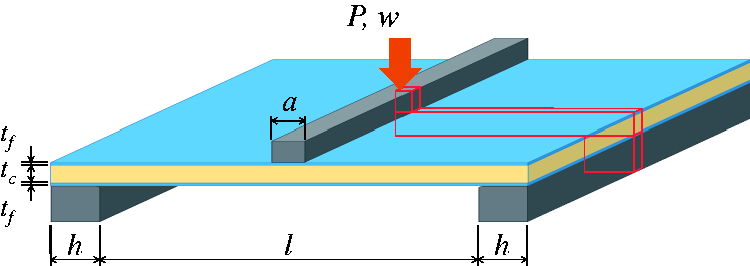
Schematic of the analytical model of sandwich lattice panel subjected to three-point bending.
Figure 2(a) and (b) shows the FE model and the unit-cell of the lattice core. The lattice core consists of eight identical strands with a circular cross-section connected to each other. Here, the parameter d represents the diameter, and L corresponds to the distance between the strands. The lattice core has two or three layers of unit-cells in the vertical direction. The top and bottom facesheets were discretized using four-node quadrilateral shell elements, and the strands of lattice core were discretized using two-node beam elements. All strands are divided into around 20 beam elements in order to minimize the effects of element size on the end result.
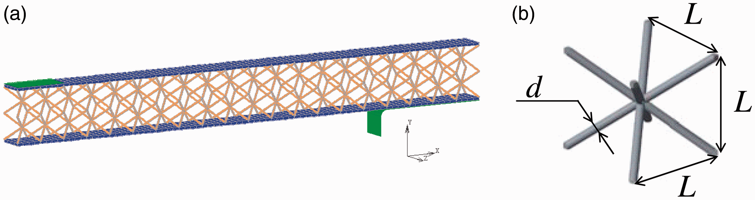
(a) FE model of lattice-cored sandwich panel, (b) Geometry of unit-cell of the lattice core.
In this calculation, contact between the loading bar and the facesheet, as well as the support and the facesheet and self-contact of the lattice core are considered. The frictional coefficient for all elements is ignored.
Figure 3(a) and (b) shows the boundary conditions applied in the FE model. At the front and rear edges of the core, all movement in the z-direction was prevented, since the model was located in the middle of the panel.
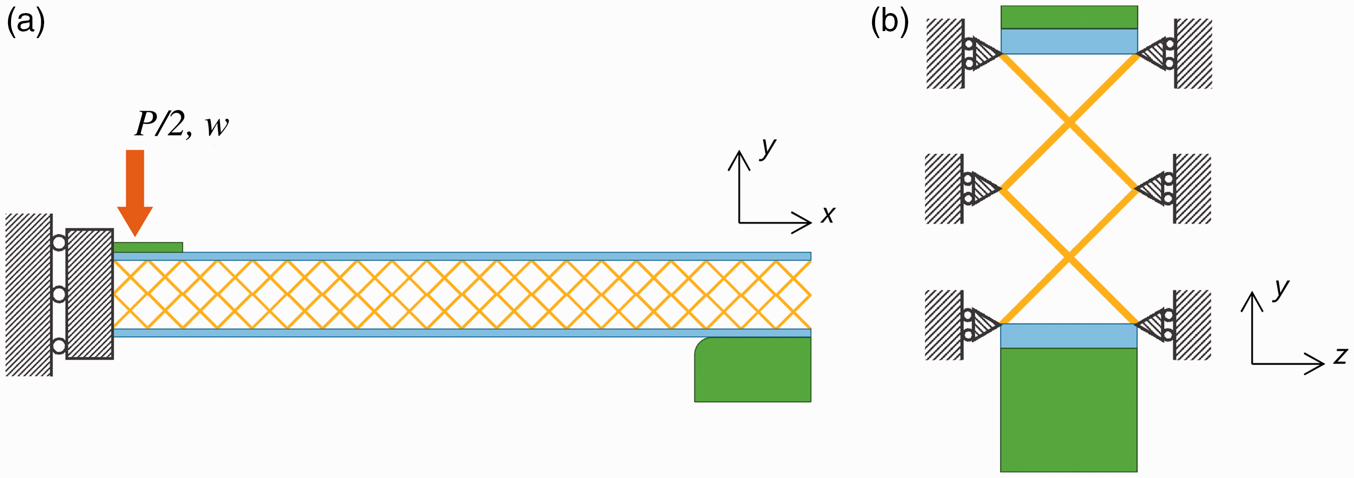
Boundary and loading conditions (a) viewed on xy-plane and (b) vied on yz-plane.
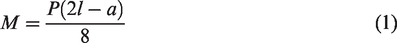
Here, the rigid loading bar is displaced quasi-statically, and the bending moment M is calculated from the reaction force P, that is, M is given by the following equation
Concerning the material properties, it is assumed that the complete sandwich plate, with its lattice core, is made of stainless steel (SUS316L), fabricated by a metal 3D printer, and it is also assumed that it behaves as a homogeneous and isotropic elastoplastic material. The stress–strain relationship can be expressed in the following manner
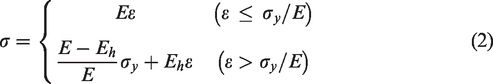
Here, E, Eh and σy represent the Young’s modulus, the strain hardening coefficient and the initial yield stress, respectively. Based on a former study [20], the values of Young’s modulus E and the plastic yield stress σy were set to 140 GPa and 144 MPa, respectively, and the Poisson’s ratio ν and the strain hardening coefficient Eh were taken as 0.3 and 1400 MPa, respectively.
In these numerical calculations, the updated Lagrange method was used to formulate the geometric nonlinear behaviour, and the Newton-Raphson method and the return-mapping method were used to solve the nonlinear equation.
Summary of the predictions of the initial failure loads for the foam core sandwich panel
As mentioned in the Introduction, the failure mechanisms in a foam-cored sandwich panel subjected to three-point bending can be classified into five failure modes: plastic yielding in the facesheets, wrinkling and indentation in the top facesheet, shear yielding of the core and delamination between the core and facesheets. For example, indentation of the facesheet beneath the loading bar may occur when the contact area between the loading bar and the facesheet becomes small. However, this type of failure can be avoided when a flat-shaped loading bar is used during the three-point bending test. In addition, the delamination mode can be avoided if the skin-core interface is sufficiently strong. Based on these assumptions, the above two modes are not considered in this study. Instead, the remaining three failure modes of the lattice core sandwich panels were considered in our numerical investigations. The estimation of the failure load for each of these failure modes in foam-cored panels is discussed in the following section.
Yielding in the facesheets
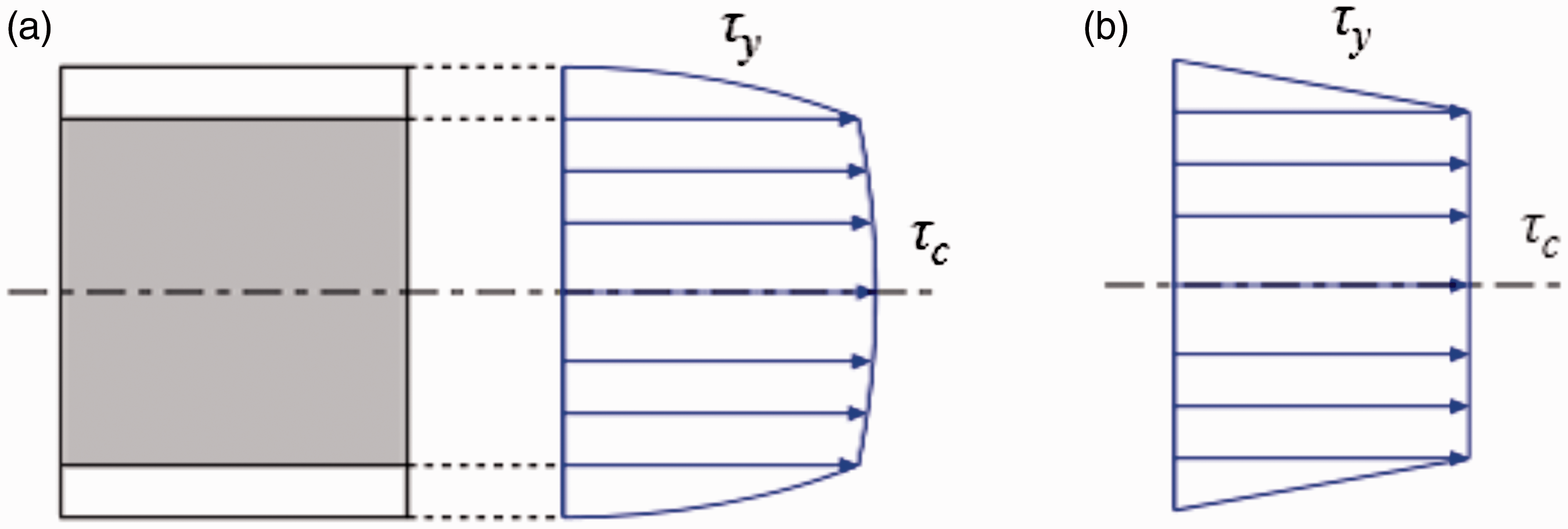
Regarding the facesheet yielding mode, a number of predictive methods for the failure load have been proposed in the literature. For example, Triantafillou and Gibson [3] assumed that yielding in the facesheets occurs when the in-plane normal stress in the facesheet reaches the yield stress of the facesheet σyf. Based on classical plate theory, the normal stress σf in the facesheet at a distance y from the neutral surface of the panel can be written as [3]

Here, in general, the flexural rigidity of a sandwich panel can be described using the following equation

The parameter b represents the depth of the sandwich panel, Ef and
In this study, equation (5) is used to describe the bending rigidity of the sandwich panel. As shown in Figure 4(a) and (b), if both facesheets are thin and rigid compared to the core, the normal stress in the facesheets can be taken as approximately constant, and the shear stress in the facesheets can be neglected. Using equations (1), (3) and (5) with
Approximation of the normal stress distribution (a) the exact distribution; and (b) the approximate distribution.
A prediction of the initial failure load, Pf, for this mode was also proposed by Qin et al. [12] Here, they assumed that the facesheet may yield when the maximum bending moment in the panel reaches the plastic collapse moment of the cross-section. In their analysis, it is assumed that the normal stress in the core also reaches the yield strength
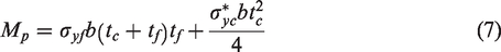
Schematic of the stress distribution at which a sandwich beam fails due to facesheet yield.
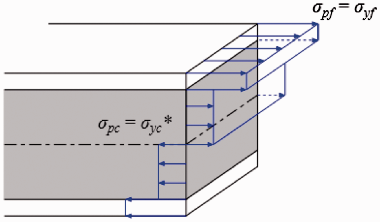
Thus, using equations (1) and (7), the initial failure load Pf can be derived as follows

Wrinkling of the facesheet
Concerning the facesheet wrinkling mode, it is assumed that the top facesheet and the upper surface of the foam core undergo the same deformation in the y-direction when wrinkling occurs in the top facesheet. The corresponding normal stress then acts between the facesheet and the core surface. Based on these assumptions, Allen [24] presented an estimation of the critical stress σcr, written as
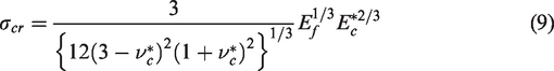
Here,
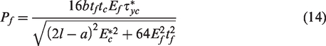
The top facesheet buckles in a wrinkle-like manner when the normal stress σf in the facesheet reaches the critical stress σcr. Thus, using equations (1), (3), (5) and (9), one can obtain the initial failure load, Pf, due to facesheet wrinkling, namely
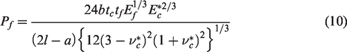
Here,
Shear yielding in the core
According to Triantafillou and Gibson [3], failure due to shear yielding in the core occurs when the maximum shear stress in the core reaches the shear yield strength
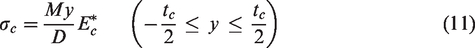

The shear stress distribution: (a) the exact distribution; and (b) the approximate distribution.
The maximum shear stress
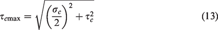
Using equations (1), (5), (11), (12) and (13) with
Here,
A similar yielding mode was also investigated analytically by Zhang et al. [14]. In their approach, it is assumed that the core shear mode involves the generation of eight plastic hinges in the facesheets at the points shown in Figure 7. The initial failure load is determined by equating the work done by the applied load to the energy consumption in the plastic hinges and the internal work done by the shear stresses in the core. The failure load due to core shear yielding can be written as
The deformation at which a sandwich beam fails due to core shear.
Results and discussion
Failure behaviour of the lattice-cored sandwich panel
In the FE analysis, failure of the lattice-cored sandwich panels included the same modes (yielding in the facesheets, wrinkling of the facesheet and shear yielding in the core) as those observed in foam-cored panels. Typical examples of the load-deflection curves for these three failure modes are shown in Figure 8(a) to (c), respectively.
Load–deflection curves from the FEM simulations: (a) facesheet yield (
The marks on the curves indicate the initial failure load for each mode. All of the curves show a linear load–deflection relationship before initial failure of the panel. For example, after yielding in Figure 8(a), the load increased as a result of strain hardening. The panel subsequently underwent wrinkling in the uppermost facesheet and deformed in the same manner as that associated with the facesheet wrinkling mode. Both facesheet wrinkling and shear yielding in the core caused a sudden reduction in load. As deformation continued after core shear failure, there were minor fluctuations in the load. Such fluctuations may be associated with the fact that each lattice cell in the core underwent shear yielding one after the other. The locations of the total equivalent plastic strain corresponding to the examples in Figure 8(a) to (c) are shown in Figure 9(a) to (c), respectively.
The locations of the total equivalent plastic strain: (a) facesheet yield (
Failure due to facesheet yielding was initiated from the lower facesheet directly below the flat loading bar. The whole panel deformed in a smooth curve without local denting or deflection in this failure mode. In contrast, as shown in Figure 9(b), facesheet wrinkling occurred in the top facesheet near the loading bar. In this case, only the facesheet deformed in a wrinkle-like shape, with the lattice-junction points acting as fulcrums. Also, core shear failure first occurred near the loading bar and the support. The magnitude of plastic strain distributed near the support was greater than that generated near the loading bar. The expanded view (Figure 9(c)) highlights the minor local deflections that occur in the facesheets.
Figure 10 summarizes the results of the FE analyses as a function of the thickness-to-length ratio
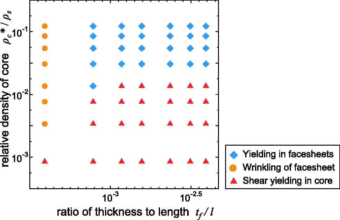
Failure predictions for the lattice-cored panel from the FE analyses.
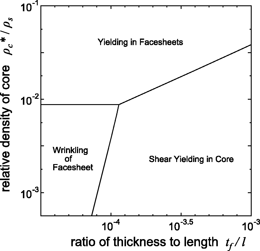
The failure mode map for the foam-cored panel.
Following a comparison with the failure mode map for the foam-cored panel, it is noted that the region of shear yielding in the lattice core is smaller in both the horizontal and vertical directions. This may be due to the fact that the shear yield stress
In the foam-cored panel, facesheet wrinkling failure occurs only when
Prediction of the initial failure loads for the lattice-cored sandwich panel
As shown in Figures 10 and 11, the failure mode map for the lattice-cored sandwich panel is similar to that of a conventional foam-cored sandwich panel. The mode which returns the lowest failure load becomes the dominant failure mode for the panel with certain design parameters. In the following, the prediction of the failure load for the lattice-cored sandwich panel is discussed, which is based on the analytical equations for foam-cored panels and the deformation behaviour obtained by the FE analysis.
Yielding in the facesheets
Figure 12(a) and (b) shows the variation of the failure load for some combinations of
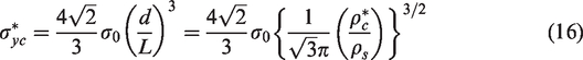
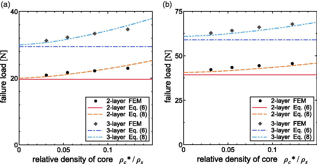
The initial failure loads for facesheet yield mode: (a)
In equation (16), σ0 indicates the flow stress considering the strain-hardening effect [23].
It can be seen that there is a large discrepancy between the FE results and the estimations from equation (6). In contrast, the predictions given by equation (8) are in fairly good agreement with the FE results. Such trends can be explained briefly as follows. Basically, the lattice core can be regarded as an open cell core, and the conventional foam core is effectively a closed cell core structure. The yielding stress of the lattice core is smaller than that of the foam structure for the same relative density. As a reference, the yield stress of a conventional foam core, as given by Gibson et al. [1] can be written as follows
Here, Es represents the Young’s modulus of the core material. As a result, when the bending stress in the facesheets reaches the yield stress, some parts of the lattice core also reach the plastic range, due to the low value of the yield stress when the lattice-cored panel fails. This suggests that the effect of failure in the core is not negligible, and thus equation (6) is unsuitable for estimating the failure load in the lattice-cored panel.
Finally, the analytical equation for estimating the initial failure load in the lattice-cored panel under facesheet yielding failure can be shown to be
Wrinkling of the facesheet
Figure 13 shows the variation of failure load Pf and relative density of lattice core

The initial failure load for the facesheet wrinkling mode (
It can be seen that there is a significant difference between the FE results and the predictions given by equations (10) and (19), especially when
Figure 14 represents a simplified wrinkling deformation model of the top side of facesheet under an axial load F. Here, this model can be considered as a continuous beam connected to lattice cores under axial compression. This is an indeterminate problem, and the continuous conditions of the bending angle and deformation at connecting points should be considered. Further details are given in Appendix 1. The final result for the failure load Pf for the facesheet wrinkling mode is as follows
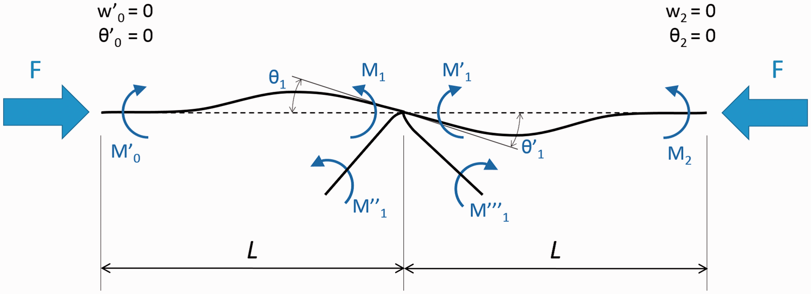
The buckling response of a continuous beam with both ends fixed.
The solution of equation (20) is shown in Figure 15 and compared with the results of the FE simulation. The calculated failure loads are in fairly good agreement with the FE results.
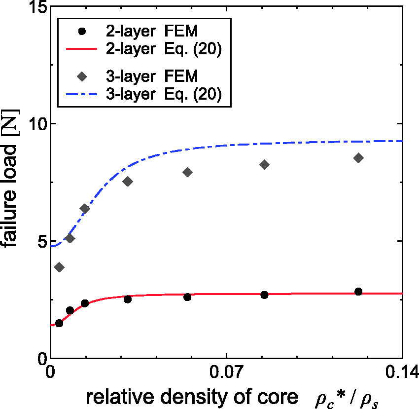
The initial failure loads for facesheet wrinkling mode (
Shear yielding in the core
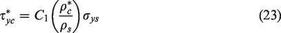
The shear yield strength
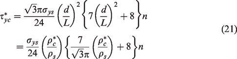
Here, the non-dimensional number n is defined as
The initial failure loads of the two-layer lattice-cored panel under the core shear mode calculated from equations (14) and (15) are shown in Figure 16 with the FE results.
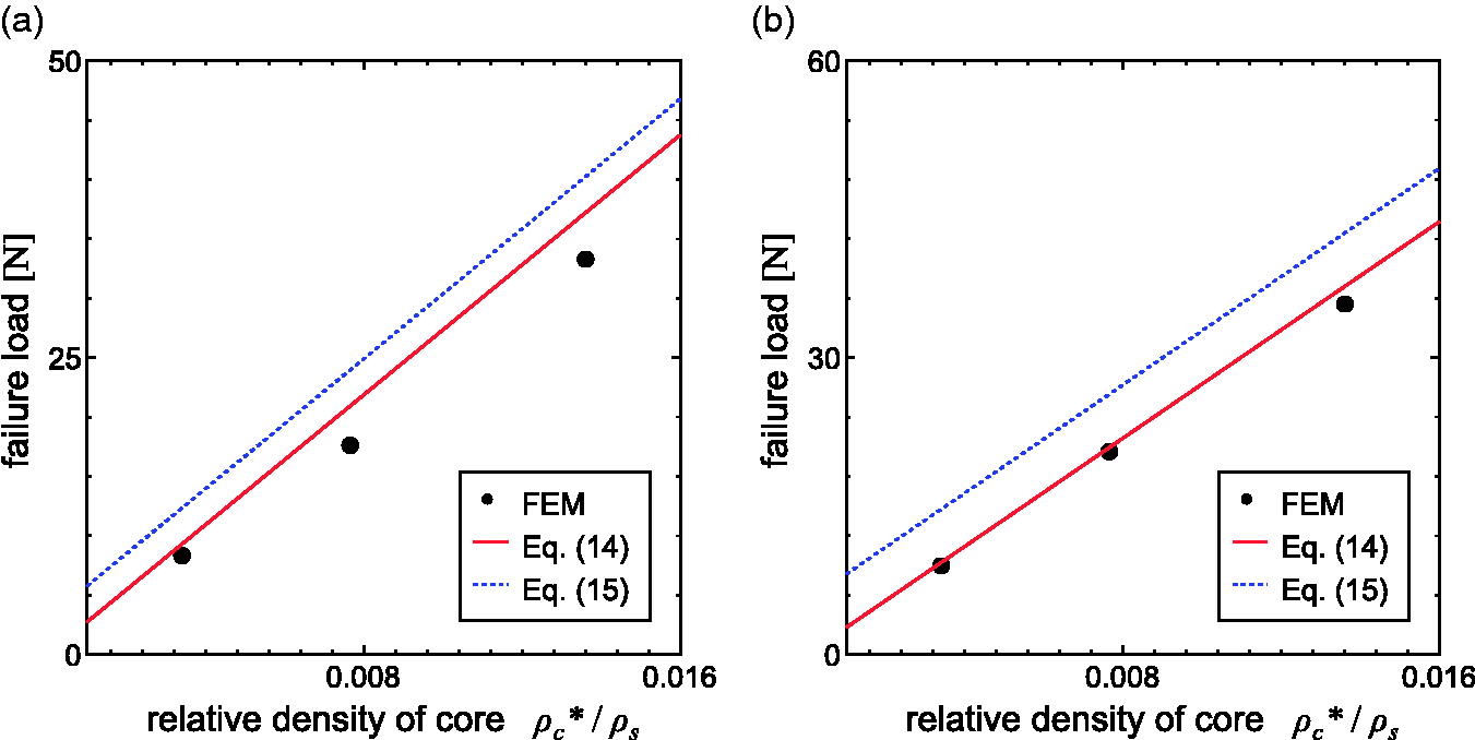
The initial failure load for the core shear mode (two-layer): (a)
The calculated failure loads are in good agreement with the FE results, especially when equation (14) is used.
Equation (21) cannot be applied when the lattice-cored panel has more than three layers in its core because of the unfixed layers of unit-cells in the center. Figure 17 shows the relationship between the shear yield strength
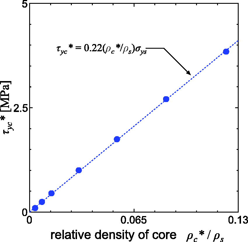
The relationship between the shear yield strength and the relative density for the lattice core (three-layer).
As seen from Figure 17, the shear yield strength
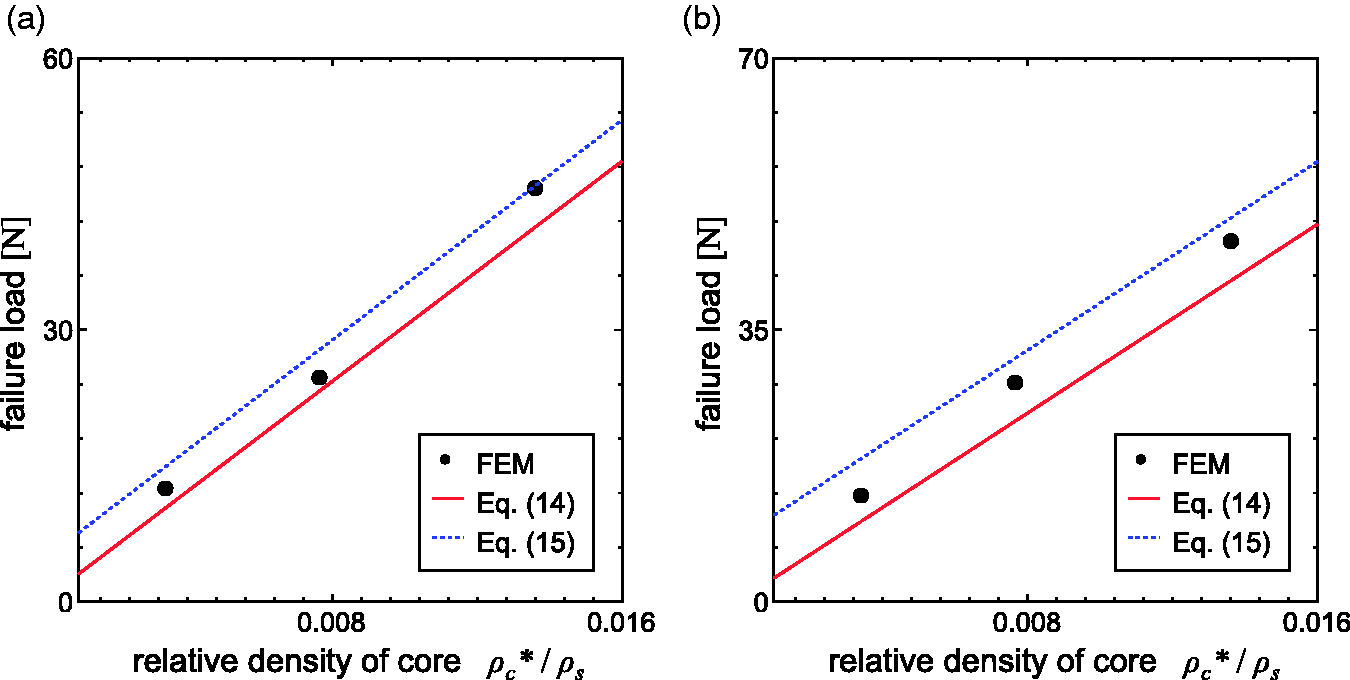
The initial failure load for the core shear mode (three-layer): (a)
The FE and calculated results indicate that the failure load for the core shear mode is largely predictable using the failure equations.
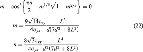
Substituting equation (19) into equation (14), the failure associated with core shear occurs in lattice-cored beam when
The failure mode map for the lattice-cored beam
The analytical equations for the failure loads for each of the three modes are listed in Table 1. All three equations depend on the parameters tf/l and
The initial failure loads for the lattice-cored sandwich beam.
Note: u depends on tf/l and
The failure mode map for the two-layer lattice-cored beam.
It can be seen that there is close agreement between the calculated and simulated modes. In particular, the map indicates that the facesheet wrinkling mode can be predicted by applying the equation which takes into account the shape feature of the lattice-cored panel.
Conclusions
In this study, the failure behaviour of lattice sandwich panels under three-point loading has been studied using a nonlinear finite element analysis. Based on our numerical results, the following characteristics were identified. Firstly, the failure mechanisms of a lattice-cored sandwich panel can be classified into three modes; facesheet yielding, facesheet wrinkling and core shear. Although all these modes are also seen in the bending response of conventional foam-cored panels, the distribution of their dominant areas in the mode map is different in the lattice-cored panels. Secondary, when failure occurs due to yielding in the facesheets or shear yielding in the core, the strength of the lattice-cored panel can be evaluated in the same manner as that of a foam-cored panel. However, when wrinkle-like deformation occurs in the facesheets, the failure load can be estimated from the buckling stress of the facesheet. Thirdly, the failure mode map for the lattice-cored panel in the coordinate system tf/l and
Footnotes
Declaration of Conflicting Interests
The author(s) declared no potential conflicts of interest with respect to the research, authorship, and/or publication of this article.
Funding
The author(s) received no financial support for the research, authorship, and/or publication of this article.