
Abstract
Hybridization of face, core and their combination is of great interest to develop high performance composite sandwich panels. In this regards, hybrid core of ‘polyester pin-reinforced foam filled honeycomb sandwich panels’ was fabricated and compared with unreinforced ‘foam filled honeycomb sandwich panels’ in terms of compressive and low velocity impact performances. MATLAB image processing techniques was applied to determine the impact damage area. Incorporating reinforcing pins for connecting faces and core is an effectual way to improve interfacial bonding, also imparts through thickness properties for sandwich panels. Compression tests performed on the sandwich panels revealed that the polyester pin reinforcement in foam filled honeycomb sandwich panel enhanced the load bearing capacity considerably. The low velocity impact properties such as load at initial damage, total absorbed energy were greatly improved and impact damage area reduced significantly by the addition of the pins.
Introduction
The utilization of composite sandwich structures in automobiles and civil infrastructure applications has been growing rapidly due to their low weight that leads to decrease in the total weight and fuel consumption. In addition, sandwich structures have excellent bending stiffness and capable to absorb high energy. A sandwich structure composed of two thin, strong face sheets bonded either side of a thick lightweight core [1,2]. Under flexural loading, the face sheets carry in-plane load while core retards shear load. Conversely, the main drawback of this structure, even a low impact by external objects, tool drops, etc. might initiate face sheet indentation and further causes interior damage in the form of matrix cracking, fiber breakage, face sheet debond and core crushing [3,4]. In this case, visual inspection may show minute damage in the impacted top face sheet, but considerable damage may take place between face sheets and core. Also, the damage caused by low-velocity impact may leads to considerable loss of stiffness and residual strength of the sandwich structures [5].
For a characteristic sandwich panel, the overall mechanical performance depends on three factors: the face sheet, the core, and the interface bonding between the core and face sheet [6]. Numerous studies have been carried out on low velocity impact response of sandwich panels composed of distinct face sheets and core materials [7–9]. Experimental studies on damage resistance and tolerance of sandwich structures subjected to low-velocity impacts have been carried out [10–12] and extensive attempt to increase the impact resistance of sandwich panels [13–15]. The properties of core material are considered vital to improve the impact resistance of sandwich panels [16]. The failure initiation, propagation and mechanisms of honeycomb sandwich panels under low-velocity impact have been investigated numerically [17].
Several experimental and numerical investigations revealed that delamination and debonding are perhaps the most crucial failures that occur in sandwich panels [18–20]. The interfacial debond between face/core prompts local bending deformation and diminishes the integral properties of sandwich panels. The most common method to enhance mechanical characteristics and improve interfacial bonding between face sheets and core of sandwich structures are Z-pinning [21] and tufting [22], refers to sewing the face sheets and core mutually by Z-directional or through-thickness reinforcements. Nanayakkara et al. [23] studied the through-thickness compression properties of z-pinned sandwich composites. Their experimental result shows that, the out of plane compression properties increased by over hundred percentages, because of energy absorption capacity of z-pins. Abdi et al. investigated the mechanical behavior of polymer pin reinforced foam core sandwich panel [24,25]. They reported that reinforcing foam with polymer pins increases compression, flexural and indentation properties considerably.
Moreover, through thickness pinning is to either substitute or support the existing core to increase the structural integrity and interfacial toughness of the sandwich panels [26]. Vaidya et al. [27] studied the low velocity impact response of z-pinned sandwich structures and reported that the Z-pinning lowers the damage area. Han et al. [28] experimentally and numerically investigated the low velocity impact damage characteristics of stitched sandwich panels, showing that stitching resists the growth of delamination, thus reduced damage area and increased the ultimate strength. Wallace et al. [29] studied the influence of pin reinforcement on the delaminated face sheet under in-plane compression and reported that the pinning improved the compressive strength significantly.
As the core of honeycomb sandwich panel is hollow metal, general through thickness interfacial toughening methodologies are not suitable. But it was suitable for foam filled honeycomb core. Besides, foam filled core prevents premature bending, buckling, and shear failure of honeycomb cell walls. In contrast to the unfilled honeycomb cores, the foam core exhibits improved resistance to the interface debonding and delamination due to an added adhesive area of foam filled honeycomb cells [30]. Also, the filling of honeycomb core by foam improved the damage tolerance and impact resistance of sandwich panels under low velocity impact [31,32].
The objective of this investigation is to study the influence of polyester pin addition in foam filled honeycomb sandwich panels (PFHS) under compression and low velocity impact loads. Two distinct diameters of pins 2 and 3 mm were used to reinforce foam filled core and their effects were also studied. It is expected that the foam filled honeycomb and reinforced pin can complement each other to withstand the compressive and impact loading.
Experimental details
Materials and manufacturing
The sandwich panel face sheets are made of two layers of woven glass fabric (600 g) and polyester resin. Methyl ethyl ketone peroxide was used as catalyst and cobalt naphthenate as accelerator. The core material used in this study was aluminum honeycomb with 6.3 mm cell size, 0.068 mm wall thickness and 10 mm height. For filling the honeycomb core, polyurethane foam of density 52 kg/m3 was used, as evaluated following ASTM D-1622 standard. A mold with needed dimensions was prepared, in order to fill the honeycomb core with foam. The foam in solution state was poured into the mold and honeycomb core was set on it immediately with a small distance from the bottom of the mold. After the solidification of foam, it filled the honeycomb core [33].
Both foam filled honeycomb sandwich panels (FHS) and PFHS panels were fabricated by vacuum infusion method. Figure 1 illustrates the schematic representation of the difference in fabrication of FHS and PFHS panels by vacuum infusion process. In this method a glass plate was laid on a flat surface, and then a releasing agent was applied on the mold surface. The glass fabric was stacked on either sides of the foam filled honeycomb core and placed on the mold surface, and then covered with peel ply. Then the laminate was sealed by using vacuum bag and a sealant tape. To ensure the constant flow of resin, a supply pipe was installed at the inlet. Once infusing the resin, the system was cured at room temperature under vacuum for 24 hours.
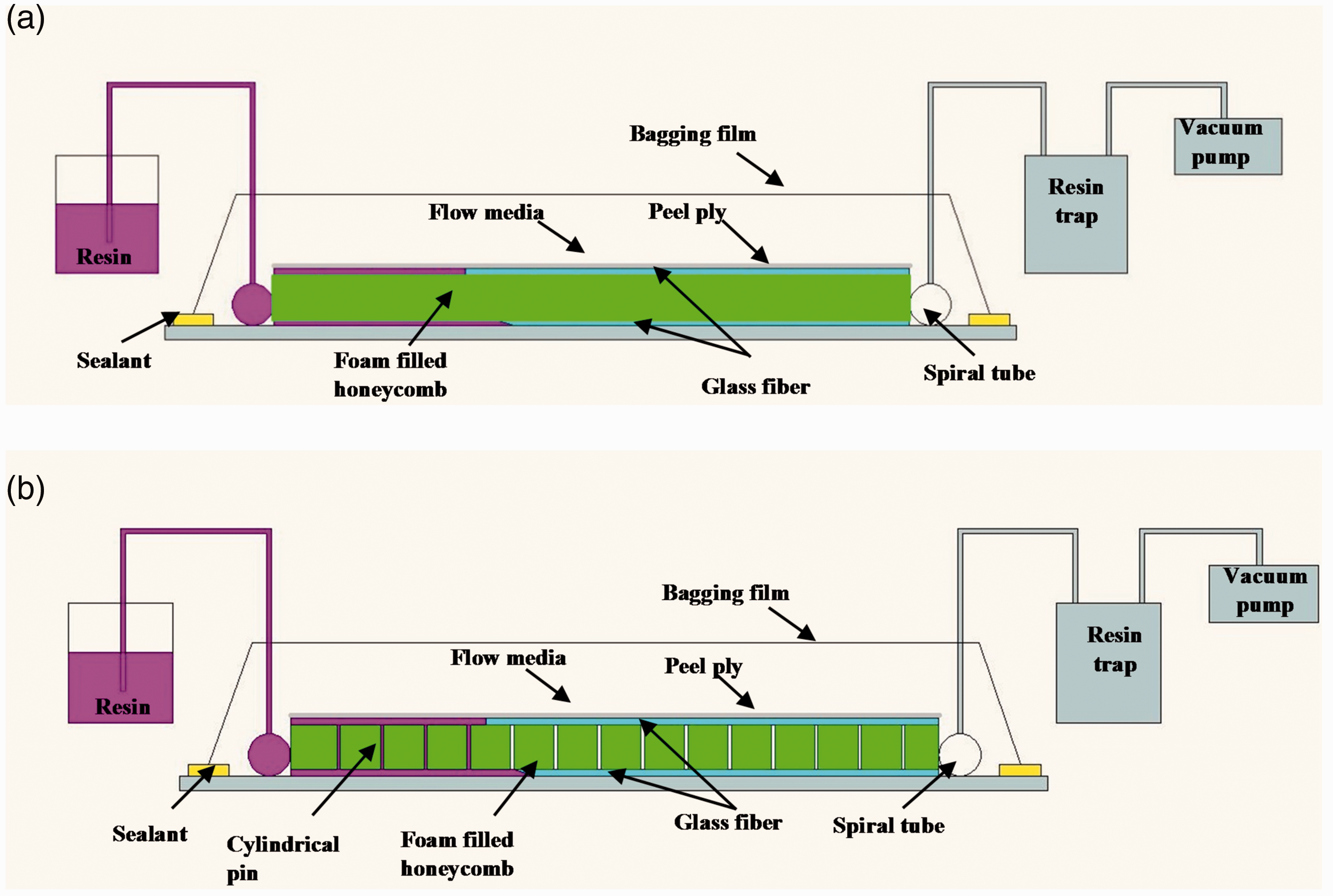
Schematic representation showing the difference in fabrication of (a) FHS panel and (b) PFHS panel by vacuum infusion process.
Figure 2 illustrates the schematic representation of PFHS panel. The enlarged view of alternate (W) and adjacent (L) arrangements of pins in the foam filled honeycomb core is depicted in Figure 3. The foam filled honeycomb core was drilled in the foam areas of hexagonal cells to make holes by using a CNC machine to form pins for PFHS panels, so that the polyester resin would flow into these holes to form the solid cylindrical pins after cured. Figure 4 shows the fabrication of PFHS panels.
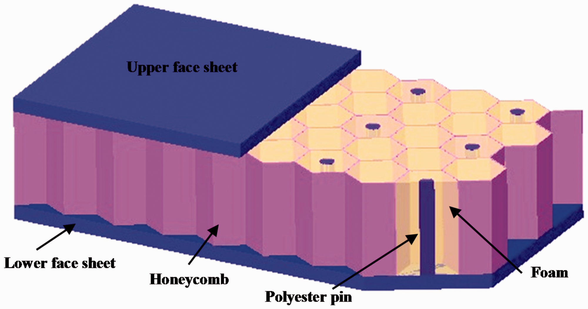
Schematic representation of PFHS panel (face sheet partially removed to show the arrangement of pins).
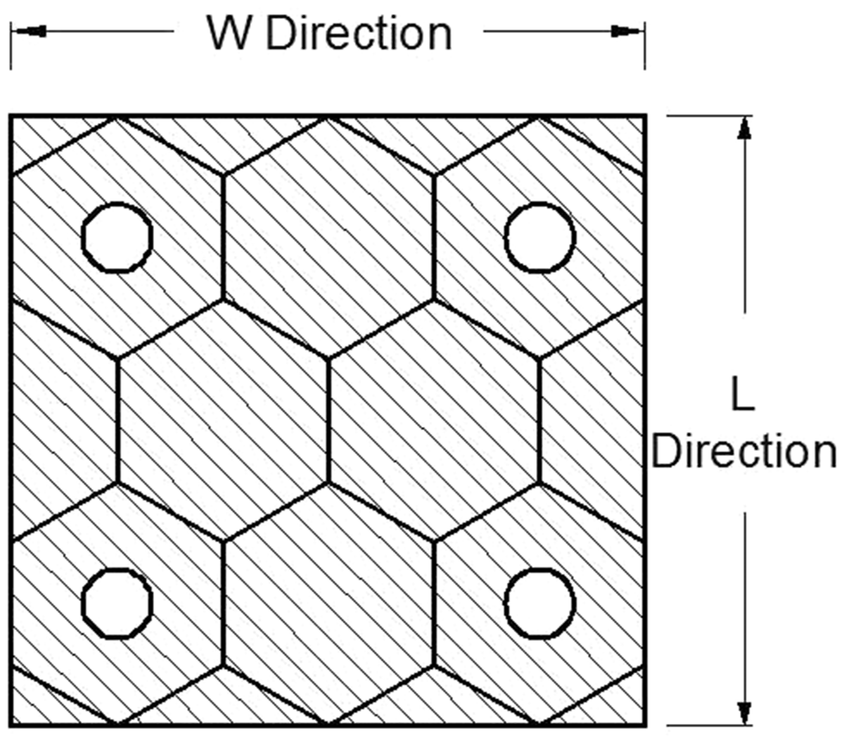
Typical arrangements of pins in PFHS panels.
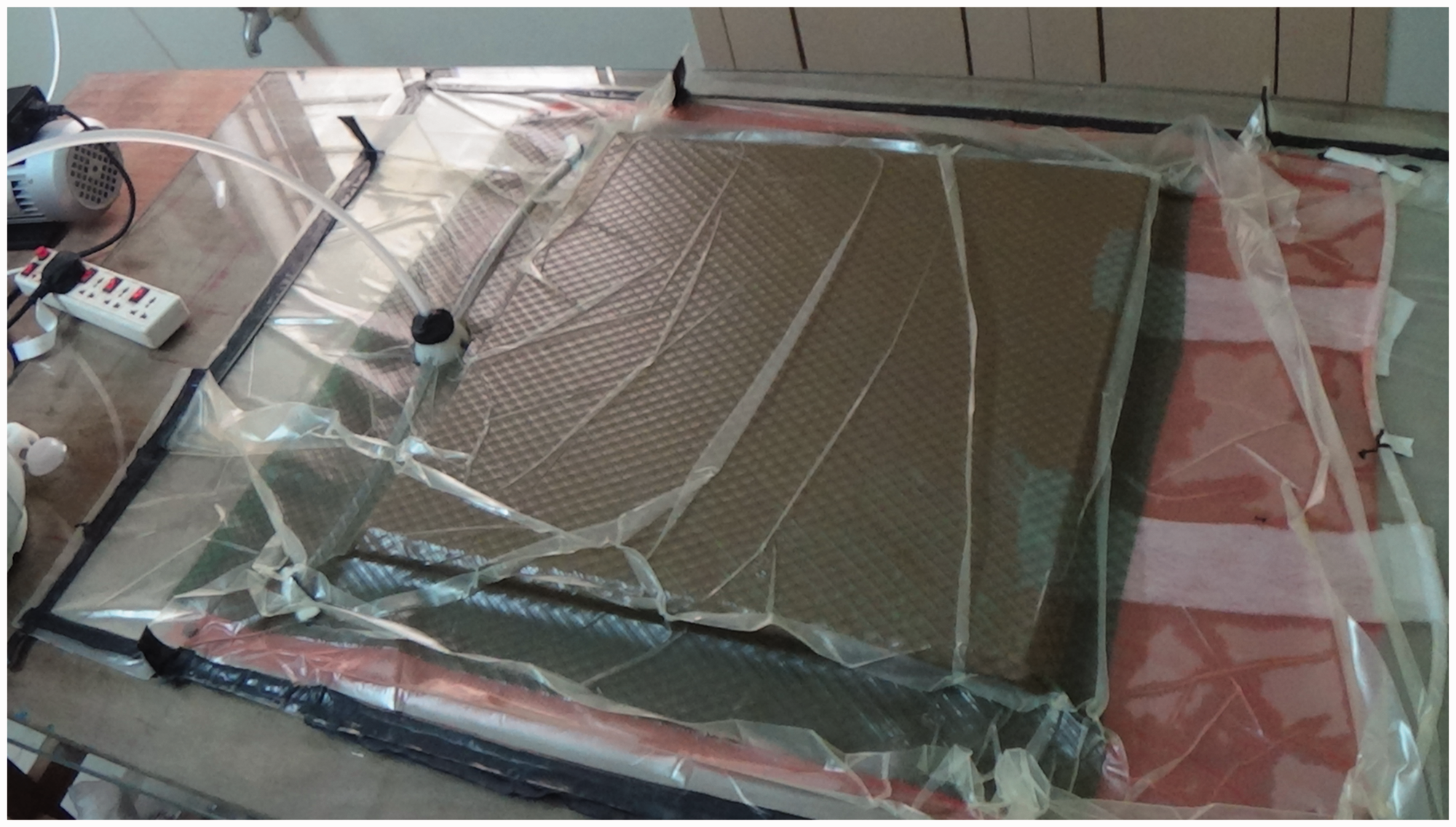
Fabrication of PFHS panel by vacuum infusion process.
The pins are made of the polyester resin that is used in the face sheets. As the manufacturing takes place together; the face sheets, foam filled honeycomb core and polyester pins were built-in to form a single inclusive solid structure.
Experimental tests
Out-of-plane compression test was performed at a constant loading rate of 1 mm/min using Kalpak Computerized Universal Testing Machine in accordance with ASTM C-365/365M standard. Samples in triplicate were used for tests to confirm the repeatability of test results.
Low-velocity impact tests were performed using Fractovis Plus Drop Weight Impact Testing Machine. The testing machine is equipped with a data acquisition system to record and store impact response of the specimens including velocity, load and absorbed energy as per ASTM D5628-10 standard. The specimen was placed in the fixture and clamped between two circular rings of 80 mm diameter using pneumatic actuation system. The details of sandwich panel samples including weight for out-of-plane compression and low velocity impact tests are listed in Table 1.
Details of samples for out-of-plane compression and low velocity impact tests.
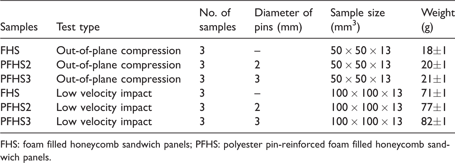
FHS: foam filled honeycomb sandwich panels; PFHS: polyester pin-reinforced foam filled honeycomb sandwich panels.
For all tests, hemispherical impactor of diameter 12.7 mm and weight 4.926 kg was used. The impactor was guided through two smooth guide columns and impact on the center of a specimen. The tests were conducted over a range of impact energies from 10 J to 50 J by varying the velocity of the impactor up to 4.5 m/s. The different impact energies were employed by varying the drop height of the impactor and thereby the impact velocity. For all tests, care was taken to ensure that the impactor would not impact directly on a point over a pin to minimize the effect of penetration point on the acquired results. After testing, the damage on specimen was captured qualitatively using a Canon EOS 700D digital camera (Canon India Private Limited India). The damage area was measured qualitatively by using MATLAB 7.9 image processing tool [34,35].
Results and discussion
Out-of-plane compression tests
The FHS panel and PFHS panels with two different pin diameters 2 mm and 3 mm were tested under out-of-plane compression to determine the effect of pin incorporation. Figure 5 shows the load–deflection response of the sandwich panels subjected to out-of-plane compression loading.
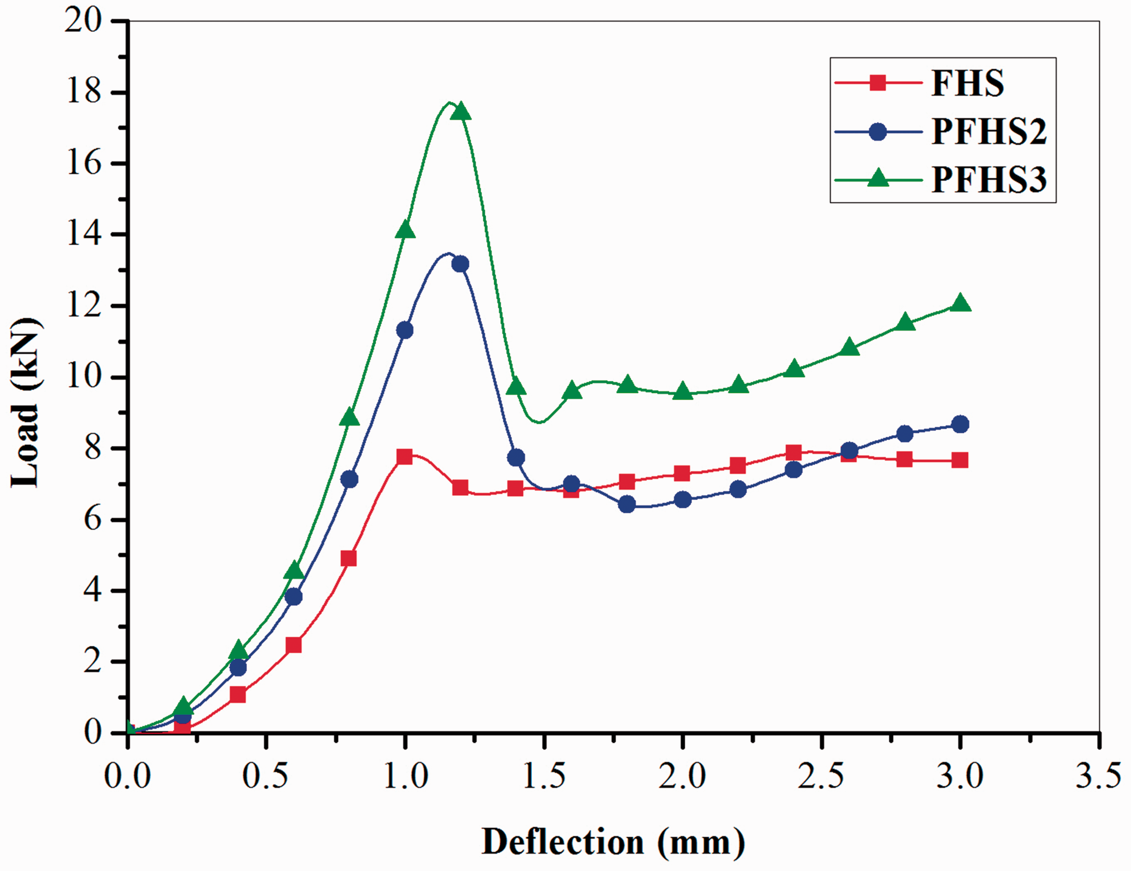
Load–deflection curves of the sandwich panels subjected to out-of-plane compression loading.
For both FHS and PFHS panels, the load declines after reaching a maximum value due to the initiation of failure. In FHS panel, the decline in the load was caused by honeycomb core cell wall buckling and in PFHS panels, due to initiation of cracks in pins. Also, compared to the FHS panel, there is a considerable improvement in compression properties of pin incorporated PFHS panels. The load bearing capability of FHS panel is 8.23 kN, whereas it is 13.81 kN and 17.26 kN for PFHS2 and PFHS3 panels, respectively. The improvement in load bearing capability of PFHS2 and PFHS3 panel is 67.8% and 109.7% higher than FHS panel, respectively. In PFHS panels, vast improvement in the compression properties is due to the reinforced polyester pins, since the out-of-plane compression properties of polyester pins are high, compared to the foam filled honeycomb core alone. The similar result is obtained for sandwich panel through thickness epoxy pins reinforced polyethylene foam core [36].
After the initial failure of the FHS panel, the load continued to increase owing to the densification of the foam filled honeycomb core. The presence of foam in the honeycomb core increases the resistance of cell wall buckling. Similarly, after the initial failure of PFHS panels the load carrying capacity increases as a result of the densification of core through crushing of pins and foam filled honeycomb core.
Figure 6 shows the out-of-plane compression tested FHS and PFHS specimens. As seen from the figure, the FHS specimen crushed uniformly because of reduced local densification of the foam filled honeycomb core [37], However, the PFHS specimens crushed non-uniformly due to the presence of incorporated hard polyester pins.
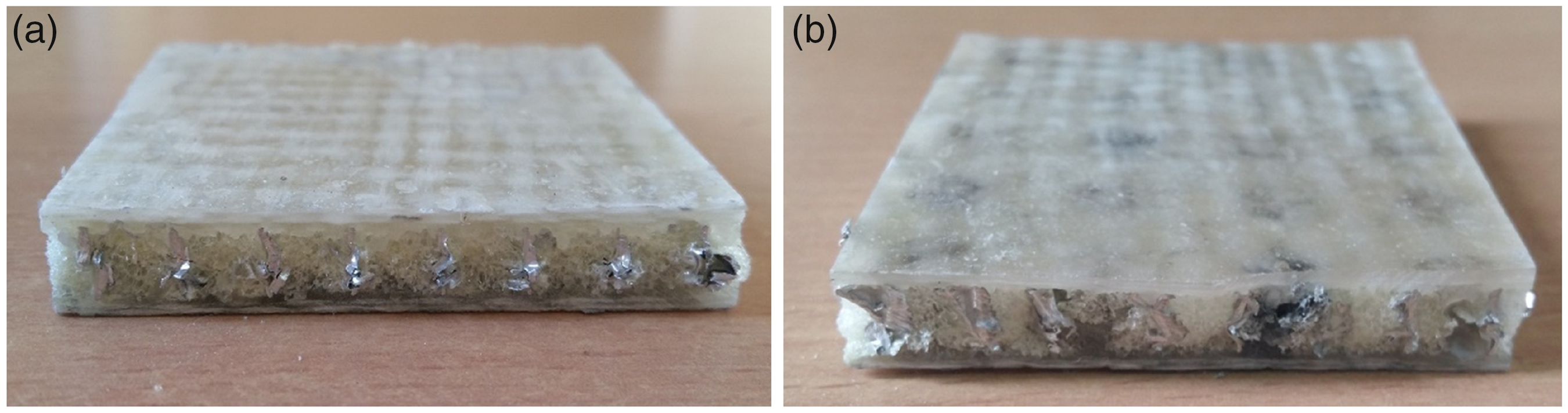
Specimens after out-of-plane compression test: (a) FHS and (b) PFHS.
The specific initial failure load of PFHS2 and PFHS3 panels is increased by 51.94% and 88.9% than FHS panels due to the incorporated polyester pins. Therefore, incorporated polyester pins in foam filled honeycomb core improved the out-of-plane compression properties of sandwich panels considerably.
Low velocity impact test
Contact force–time curves of FHS and PFHS sandwich panels
The force–time curves of FHS and PFHS panels at different impact energy level are shown in Figure 7. The force and time is a vital variable in impact analysis. Contact force is defined as the reaction force applied from the specimen to the impactor [38]. From Figure 7, it can be seen that for testing of specimen at each particular impact energy, impactor exhibits different contact time. This is due to the addition of polyester pins in foam filled honeycomb core sandwich panels.
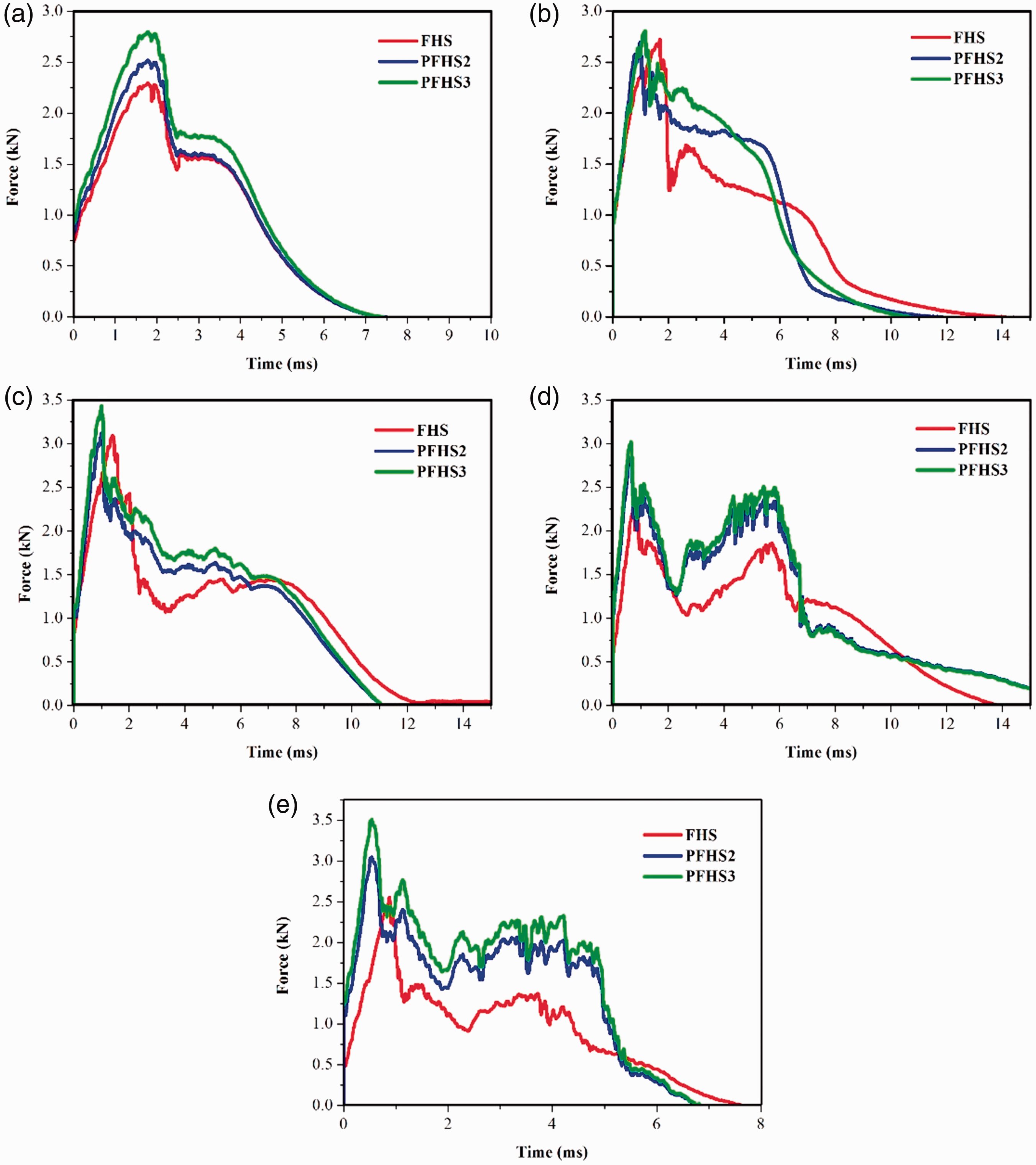
Force–time histories of FHS and PFHS panels under different impact energy levels (a) 10 J, (b) 20 J, (c) 30 J, (d) 40 J, and (e) 50 J.
The force–time curve was initially linear up to the peak force, which is termed as initial damage point. The initial damage point is defined as the maximum load carrying capability of the specimen. The damage at this point generally corresponds to the matrix failure. For all five impact energy levels, each specimen showed different initial damage point. After the damage initiation, the sandwich panel experiences a reduction on stiffness that leads to a drop in the force–time curve. The second peak force in the force–time curve relates to the contact of impactor on the inner core through the penetration of top face sheet. The damages at this point obviously includes fiber delamination and breakage of the top face sheet.
The load bearing capability of FHS and PFHS panels with two different diameters was compared and it is revealed that the polyester pin reinforced foam filled honeycomb cored PFHS2 and PFHS3 specimens were better than foam filled honeycomb cored FHS specimen. From Figure 7(a), at impact energy of 10 J it was seen that PFHS3 panel had the maximum value of 2.87 kN followed by PFHS2 panel with 2.52 kN, whereas FHS panel was 2.11 kN, respectively. The specific load bearing capacity of PFHS2 and PFHS3 panels is 10.13% and 17.81% higher than FHS panel. The improvement in load bearing capability is attributed to the high bonding strength and stiffness in the face/core interfaces provided by the incorporation of pins in the PFHS panels. By comparing the impact properties of PFHS panels with a pin diameter of 2 and 3 mm, the load carrying capability of PFHS panels with a pin diameter of 3 mm is 13.8% and 36% higher than PFHS panel with a pin diameter of 2 mm and FHS panels, respectively.
The specimen also represents different load carrying capability values with 20 J, 30 J, 40 J and 50 J impact energy levels. Compared to impact energy of 10–30 J, the peak force of specimens reduced at impact energy of 40–50 J, which is due to the impactor propagation through panel thickness and progressive accumulation of material damages [39]. As the constituent materials used for both FHS and PFHS panels are same, it is evident from the results that the inclusion of polyester pins in the foam filled core improves the load bearing capability of the PFHS sandwich panels. From Figure 7, it was observed that the time to attain peak force decreases with increase in applied impact energy. For instance, under 10 J impact energy of PFHS3 specimen (Figure 7(a)), time to attain peak force was 1.74 ms, but it was 1.172 ms, 0.972 ms, 0.744 ms and 0.534 ms under 20 J, 30 J, 40 J and 50 J impact energy levels correspondingly (Figure 7(b) to (e)). This attribute was owing to the increase in velocity of the impactor [40].
Energy absorption properties of FHS and PFHS panels sandwich panels under low velocity impact
The energy absorbed by the FHS and PFHS panels with respect to different impact energy is shown in Figure 8. It can be seen that, for the increasing impact energy level there is a slight varying influence on the energy absorption capacity of the pinned PFHS panel. At impact energy level of 10 and 20 J, the absorbed energy for both unpinned FHS and pinned PFHS panels are almost similar.
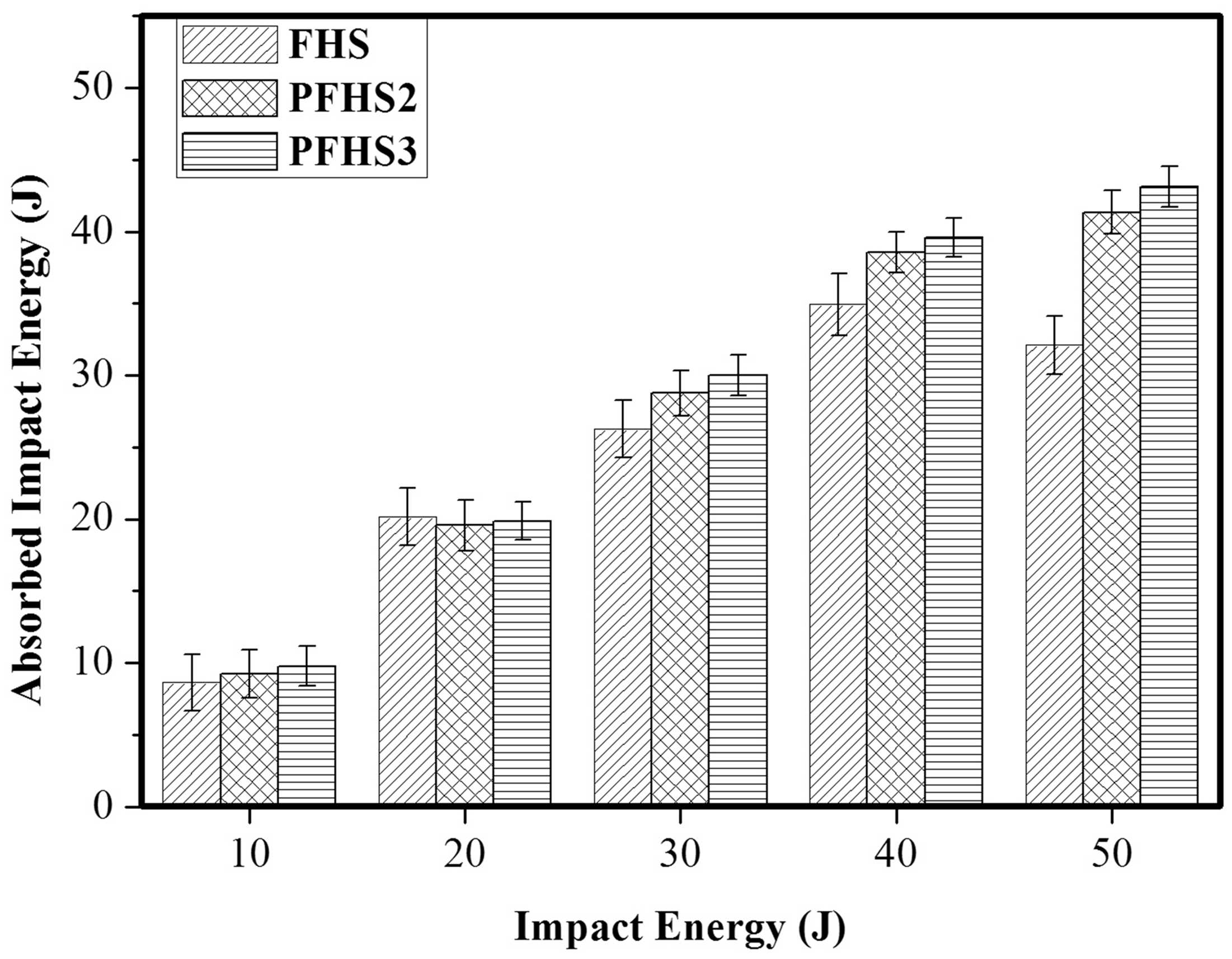
Influence of impact energy on the absorbed energy of the unpinned FHS and pinned PFHS sandwich panels.
The failure observed for PFHS panels with diameter 2 mm and 3 mm is similar. Hence the images of PFHS2 specimens at different impact energies are not given. Figures 9 and 10 compare a typical damage observed for FHS and PFHS specimens after impact loading. For all panels, the damage area was calculated by using MATLAB image processing techniques. Various stages involved in the processing of the image of impact damage for the calculation of damage area using the image processing technique are shown in Figure 11.
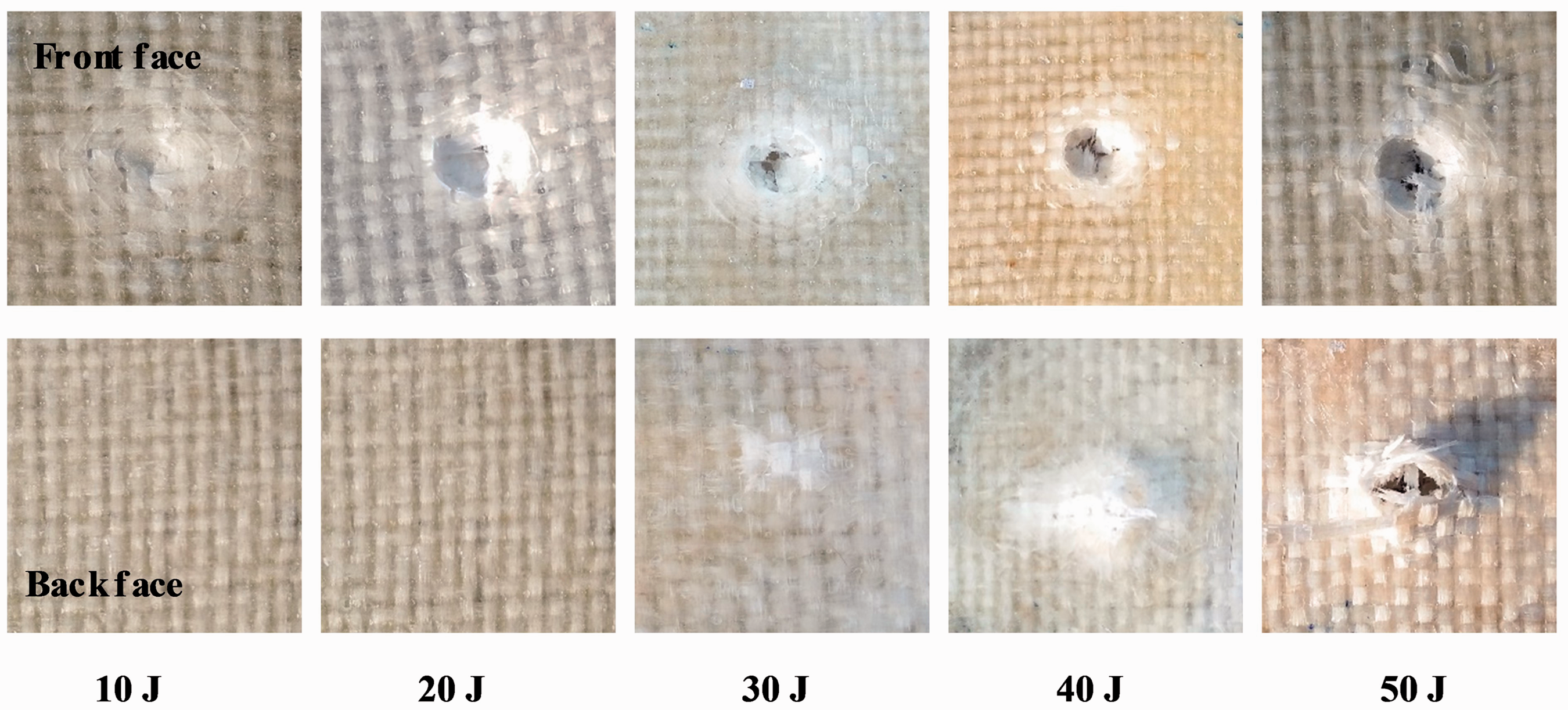
Impact damage (front and back face) observed for FHS panels.
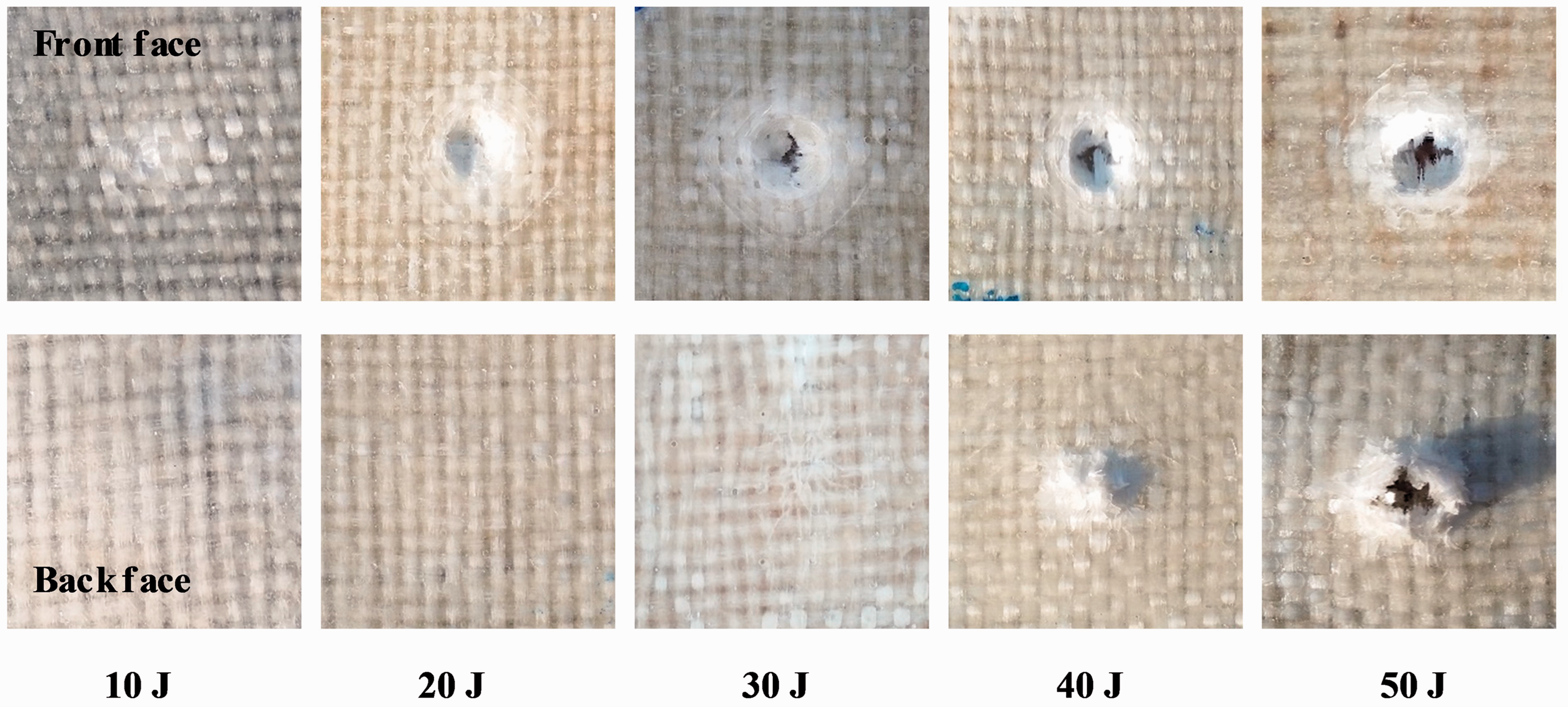
Impact damage (front and back face) observed for PFHS3 panel
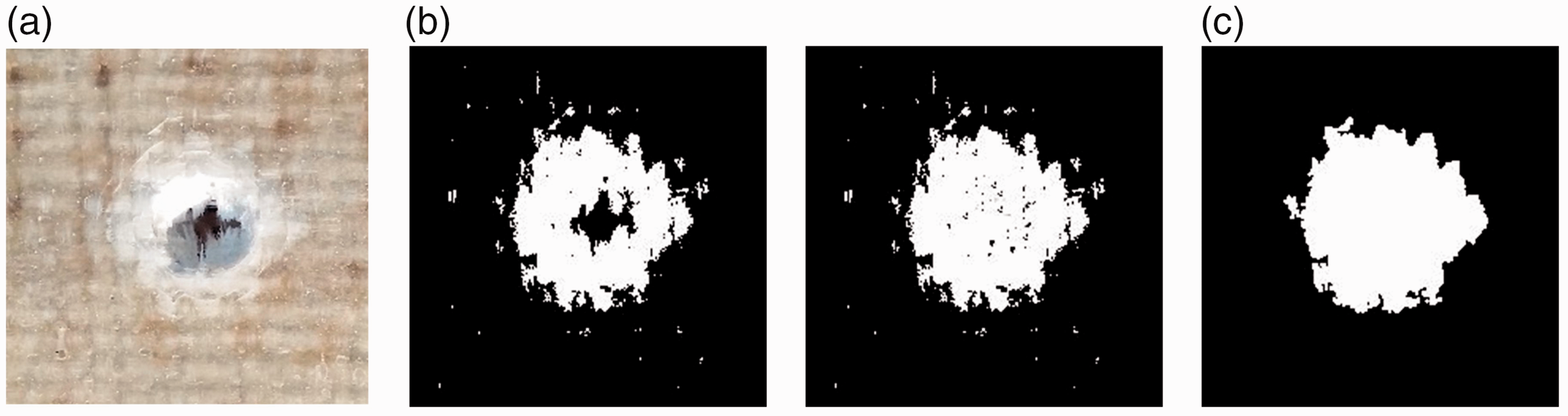
Various stages of image processing. (a) Captured image, (b) Processing of image and (c) Final image.
Visual inspection of impact tested specimens at 10 J reveals that in FHS and PFHS panels the damage is limited to localized delamination at the location of incident of impactor on the top face sheet as shown in Figures 9 and 10. Also, no breakage of fibers was observed in FHS and PFHS panels after impact. At this impact energy, the damage area for these panels is more or less equal as shown in Figure 12.
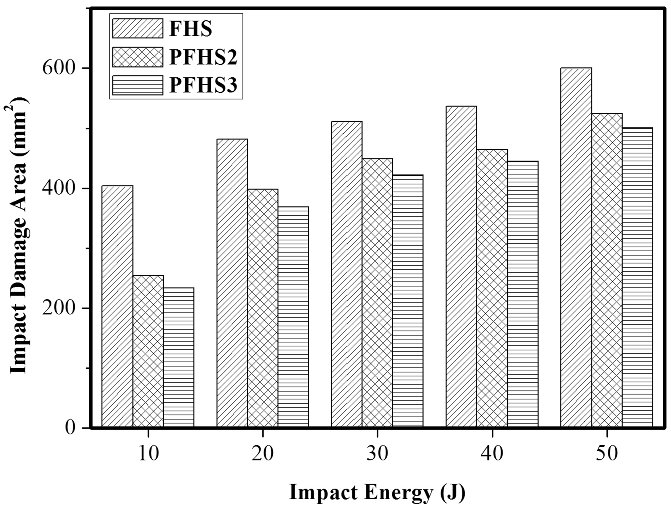
Influence of impact energy on the size of the impacted damage region for the unpinned FHS and pinned PFHS sandwich panels.
In contrast to the FHS panel, the amount of delamination damage in the face sheet of PFHS panel is less. The minimal amount of top face damage is due to high interlaminar fracture toughness promoted by the polyester pins through strong interface bonding between the faces and core [41]. At 20 J, in FHS and PFHS panel, a small dent was introduced at the impact location and observed damages include matrix crack, fiber breakage and circumferential fracture lines [42].
From Figure 8, at impact energy level of 30 J, the energy absorption capacity of the pinned PFHS3 panel is 9% and 3% higher than FHS and PFHS2 panels. These panels suffered face sheet damage and crushing of foam filled core as shown in Figures 9 and 10. Figure 13 shows the cross-sectional and microscopic image of failed FHS and PFHS3 specimens at impact energy 30 J. At this high energy, in addition to the delamination, the impact damage is extended to the core after rupturing the face sheet. Bare eye examination reveals the delamination in back face of FHS panel, whereas no damage was observed in the case of PFHS panels. However, microscopic view of FHS panel reveals delamination as well as minor cracks, but no damage was observed in PFHS panels. At this impact energy, the damage area of PFHS3 panel is 8% and 21% less than the PFHS2 and FHS panels as shown in Figure 12.
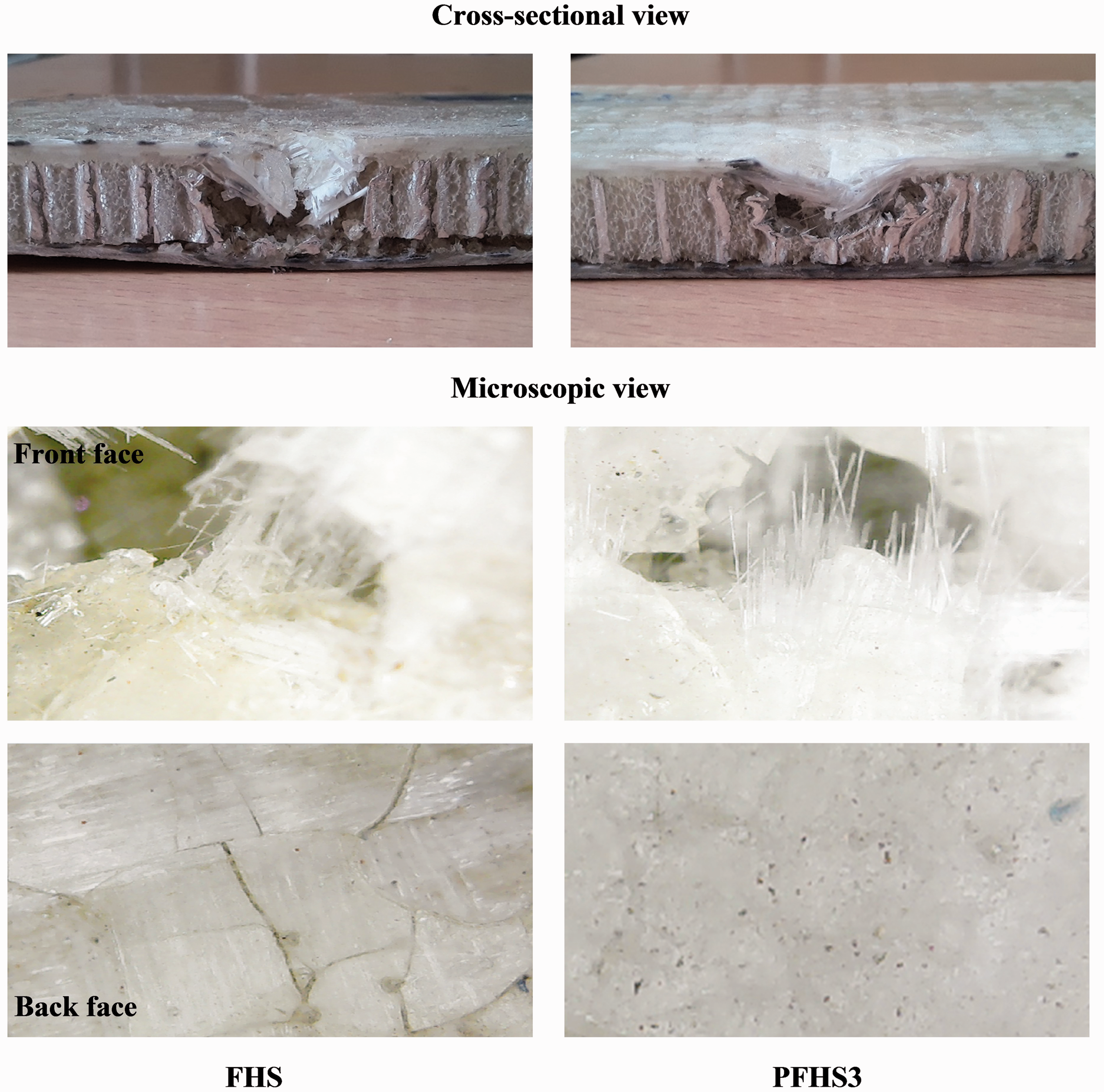
Cross-sectional view and microscopic image of failed specimens at impact energy of 30 J.
Figure 8 shows that, at impact energy of 40 and 50 J, the amount of energy absorbed by the pin reinforced PFHS panels was slightly higher than the unpinned FHS panel. At 40 J, FHS and PFHS panels experienced both face sheets damage and core crushing as shown in Figures 9 and 10. The front face sheet perforated and back face sheet delaminated outwards. Compared to the PFHS panel, the damage area at front face is higher and delamination at bottom face is considerably higher for FHS panel. The strong interface bonding provided by the pins in PFHS panels resists the delamination growth. Generally, delamination is an interior damage and so increase in delamination is an indication of much interior damage.
The damages suffered by the specimens under 50 J impact load were more severe compared to damages under 40 J impact loads. Both the FHS and PFHS specimens experienced through thickness perforation damages. From Figures 9 and 10, the void in the top face sheet denotes the point of penetration and circumferential fracture around the impact location to FHS and PFHS panels. It can be seen from Figure 12, the damage area for PFHS panels is significantly lower than FHS panel. The rear face sheet of both panels suffered radial perforation and a large area of delamination was observed compared to the top face sheet. The specific energy absorption capacity of PFHS3 panel is 17% higher than FHS panel. Therefore, polyester pin reinforcement in foam filled honeycomb core enhances the energy absorption capacity and reduced the amount of impact damage significantly. This enhancement is attributed to delamination toughening of the face sheet, interfacial toughening of the face/core as well as by strengthening the foam filled honeycomb core by reinforcing pins.
Conclusion
The polyester pin reinforcement in foam filled honeycomb core sandwich panel enhanced the compression and low velocity impact properties significantly. The low initial peak load of honeycomb based sandwich panel under compression loading drawback is overcome by pin reinforcement. Also, increasing the pin diameter, results in improved properties of PFHS3 panels than PFHS2 panels. Comparison of the load carrying capabilities, energy absorption, damage properties and failure mechanism under diverse impact energies showed that the pin reinforced PFHS panels performed better than unpinned FHS panels. The MATLAB image processing of the specimens proved that damage areas increased with increase in applied impact energy level and it was low for PFHS panels due to the high interlaminar fracture toughness promoted by the polyester pins through strong interface bonding between the faces and core. The conclusion is that, only with an insignificant increase in weight, the resulting structural performance of PFHS sandwich panel is appreciably better than FHS panels.
Footnotes
Declaration of Conflicting Interests
The author(s) declared no potential conflicts of interest with respect to the research, authorship, and/or publication of this article.
Funding
The author(s) received no financial support for the research, authorship, and/or publication of this article.