
Abstract
In this study, the effects of the core layering of sandwich structures, as well as arrangements of these layers on the ballistic resistance of the structures under high-velocity impact, were investigated. Sandwich structures consist of aluminum face-sheets (AL-1050) and polyurethane foam core with different densities. Three sandwich structures with a single-layer core of different core densities and four sandwich structures with a four-layer core of different layers arrangements were constructed. Cylindrical steel projectiles with hemispherical nose, 8 mm diameter and 20 mm length were used. The projectile impact velocity range was chosen from 180 to 320 m/s. Considering constant mass and total thickness for the core, the results of the study showed that the core layering increases the ballistic limit velocity of the sandwich structures. The ballistic limit velocity of the panels with a four-layer core of different arrangements, compared to the panel with the single-layer core, is higher from 5% to 8%. Also, for the single-layer core structure, by increasing the core density, the ballistic limit velocity was increased. Different failure mechanisms such as plugging, petaling and dishing occurred for the back face-sheet. The dishing area diameter of back face-sheets was proportional to the ballistic resistance of each sandwich structure.
Introduction
Sandwich structures have been widely used in various industries due to their high strength and toughness against low weight. The two main parts of these structures are the core and the face-sheets: the core is often made of low-density materials that are usually bulky (foam, honeycomb, etc.), and the face-sheets which are placed on both sides of the core are strong and usually thin.
In recent years, many researchers have investigated the performance of sandwich structures under high-speed loading both experimentally and numerically. They also examined a number of important parameters in energy absorption and ballistic resistance of these structures. The following is some of the studies that have been done:
Kepler [1,2] studied, empirically and analytically, the penetration in sandwich panels with PVC foam core and identified three deformation models and provided an analytical formula for them. Schubel et al. [3] studied the quasi-static behavior and low-velocity impact of sandwich panels with woven/epoxy carbon face-sheet and PVC foam core. They compared the results of the static penetration test with the results that obtained from Abaqus software, which showed a good agreement. Buitrago et al. [4] investigated the high-velocity impact on composite-honeycomb sandwich structures. They made a 3D finite element model in Abaqus software to simulate the impact on sandwich panels with carbon-fiber face-sheet and aluminum honeycomb core and evaluated their model with empirical results. They compared the simulation results regarding the residual velocity, ballistic limit and projectile contact time with the sandwich panel with experimental results. The effect of each component on sandwich panel behavior under impact load is evaluated in this model. Also, the contribution of each of the energy absorption mechanisms from the initial kinetic energy of the projectile is determined. Feli et al. [5] analytically studied two layers ceramic-composite plates resistance against impact and penetration. Considering the strain rate effect, they investigated fiber kinetic and strain energies. They also computed the projectile residual velocity, the energy absorbed by fiber, the ceramic cone residual mass and the penetration depth. Also, this process was simulated (two dimensional) in LS_Dyna by Feli and Asgari[6]. Flores-Johnson and Li [7] experimentally studied the projectile indentation in a sandwich panel with CFRP composite plates and polymer foam core in a quasi-static situation. The results showed that both the shape of the projectile and the density of foam have a significant effect on the panel energy absorption, the projectile indentation, as well as the failed region. Garcia-Castillo et al. [8] examined the behavior of sandwich structures and spacing sheets under high-velocity impact. The face sheets and the core were, respectively, made of glass/polyester and PVC foam. They checked out the residual velocity, ballistic limit velocity and the damaged zone regarding the mentioned structures. The results implied that the residual velocity and ballistic limit velocity was similar for both structures but their damaged zone was different. Ivanez et al. [9] provided a numerical simulation on the impact of a spherical projectile on composite-foam sandwich panels in Abaqus software. The results showed that by increasing the initial velocity, the residual velocity of the projectile increased and energy absorbed by the foam decreased. Rahmi et al. [10] experimentally and numerically investigated the penetration of blunt nose projectile into aluminum-foam sandwich targets. According to the tests and simulations carried out by them, increasing the density and thickness of the foam and the initial velocity of the projectile, the energy absorption of the sandwich structure also increased. Pol et al. [11] examined the ballistic properties of aluminum foam experimentally. Ghalami and Sadighi [12] experimentally and numerically investigated sandwich panels with fiber metal laminate face-sheets and polyurethane foam core under high-velocity impact. The effects of parameters such as core density, projectile initial velocity, and the face-sheet layer arrangements were studied. The results revealed that the face-sheet has the major contribution to energy absorption and the foam core is less effective than the other factors. Su et al. [13] numerically studied the behavior of sandwich panels with aluminum face-sheet and aluminum foam core under high-velocity impact. The parameters such as projectile diameter and nose, curvature and thickness of face-sheet under normal and oblique impact were studied. The results showed that the thicker and blunter projectile, a higher initial velocity of the projectile and a thicker face-sheet increase the target resistance against impact. Taherkhani et al. [14] experimentally investigated the elastic-plastic behavior of polyurethane foam under normal and oblique high-velocity impact as well as energy absorption and damaged zone of specimens. The results indicated that increasing the foam density and thickness increases the foam energy absorption as well as the damaged area behind the specimen. Jing et al. [15] numerically studied the resistance of square sandwich panels with aluminum foam core against penetration. They validated their simulation using empirical results from previous single core sandwich panels. They also investigated the process of deformation, critical speed and energy absorption of an integrated aluminum plate.
Previous studies were often carried out on sandwich structures with a single core and a constant density. In this paper, the ballistic resistance of sandwich structures with four-layer and single-layer polyurethane foam core and aluminum face-sheets was investigated. Also, the effects of the parameters of the initial velocity of the projectile, core density and different layers of arrangements of the four-layer core panels were studied. The damaged zone of sandwich panels also was investigated.
Experimental procedure
Mechanical and geometrical properties
Geometric dimensions and mechanical properties of materials used in projectiles and components of sandwich structures, e.g. face-sheets and foam cores, are as follows:
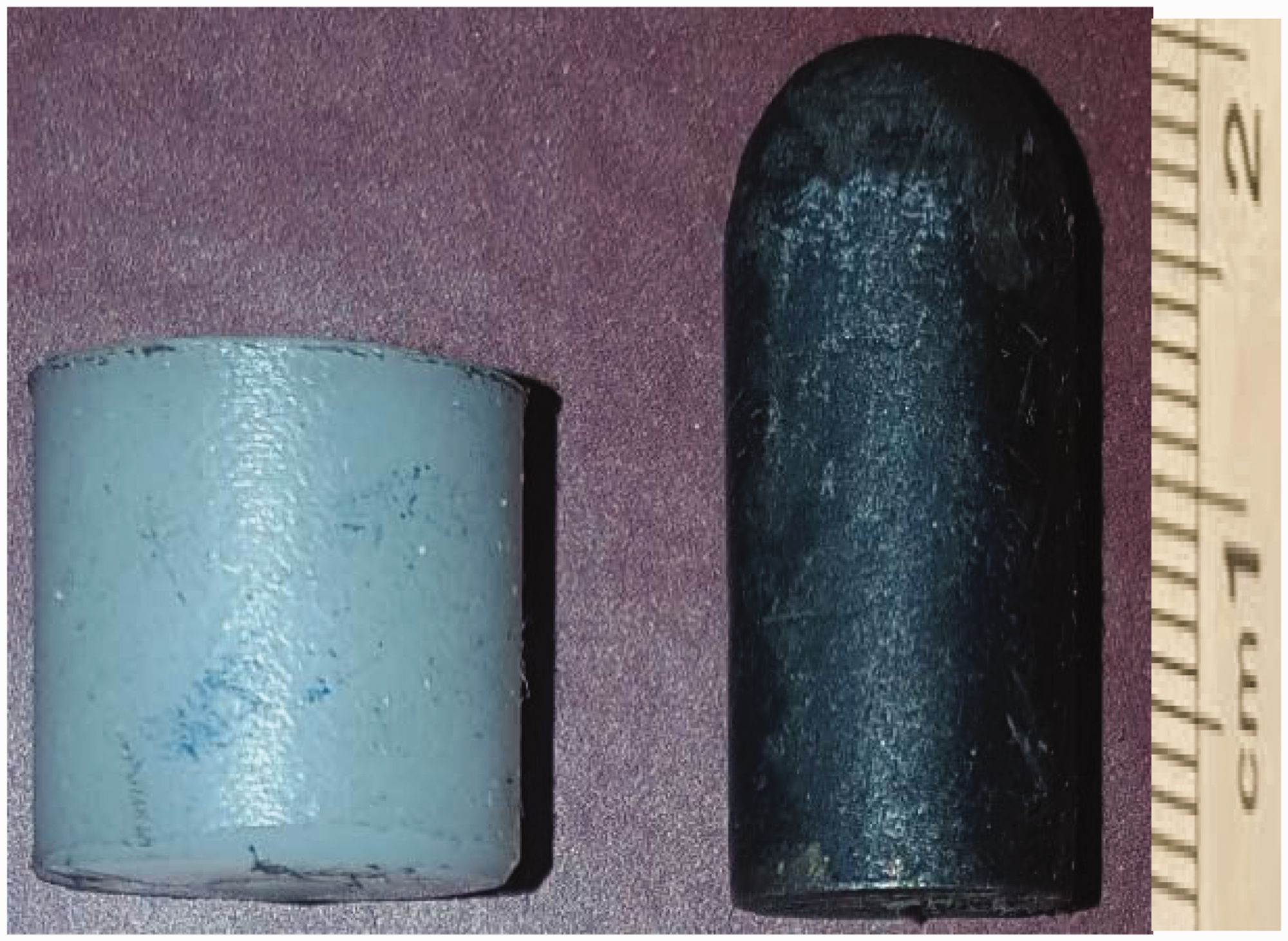
Sabot and projectile.
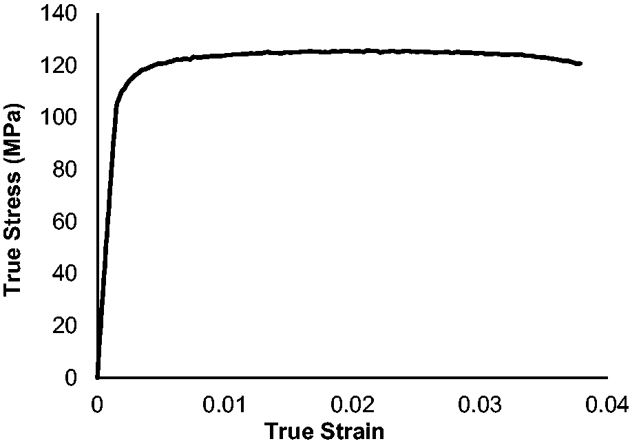
True tensile stress–strain curve of aluminum face-sheets (AL-1050).
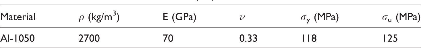
Aluminum face-sheets mechanical properties.
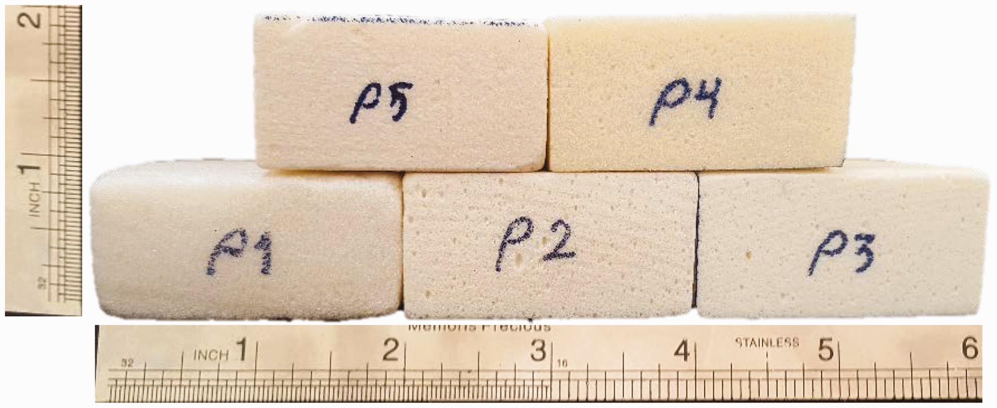
Foams specimens for compression test.
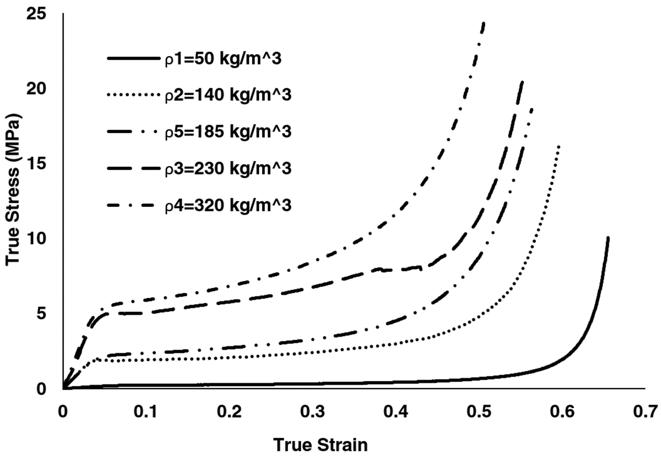
True compression stress–strain curves of foams used in sandwich structures.
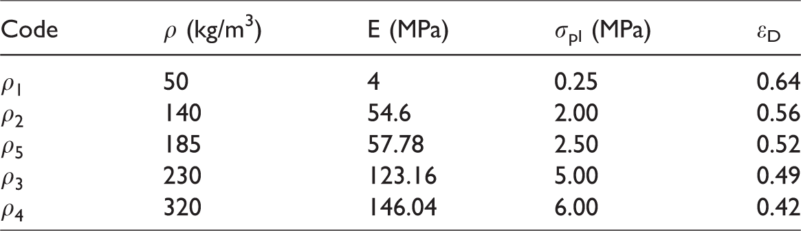
Foams mechanical properties.
Design, fabrication and coding of sandwich structure samples
Seven types of sandwich structures were considered in order to study the ballistic performance and energy absorption of them under high-velocity impact test, three of which have a monolithic single core and the remaining four have a four-layer core. These structures differ in the density and layer arrangements of foam cores. The lowest, mean and highest densities were chosen for the core, in single core sandwiches. In sandwich structures with a four-layer core, four different densities were used (except the mean density) and four different layer arrangements such as ascending, descending, ascending triangle and descending triangle were considered. In the ascending order of density, the layers are from the lowest to the highest density and in the descending order from the highest to the lowest density. In the ascending triangle density arrangement, the first and the last layers have the lowest density and the two middle layers have the highest density, and vice versa in the descending triangle density arrangement. It should be noted that the overall dimensions of all structures are constant and equal, and also the structures with four-layer core have both similar dimensions and mass as the single-layer core structure with the mean density. The density layer arrangements for sandwich structure cores are shown in Figure 5. The abscissa of this diagram represents the distance from the middle of each layer thickness to the outer surface of the front face-sheet of the sandwich panel and the ordinate defines the density. The samples coding is given in Table 3.
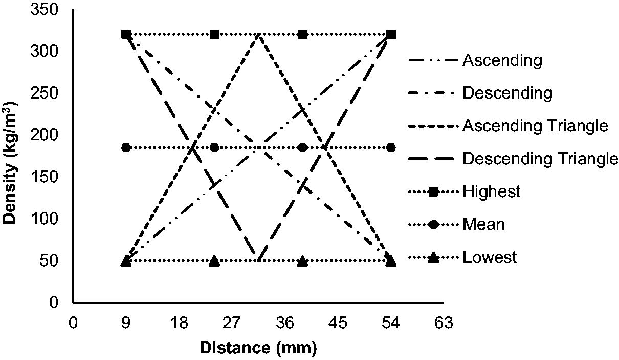
Layer density arrangements of sandwich panels cores.
Sample codes.
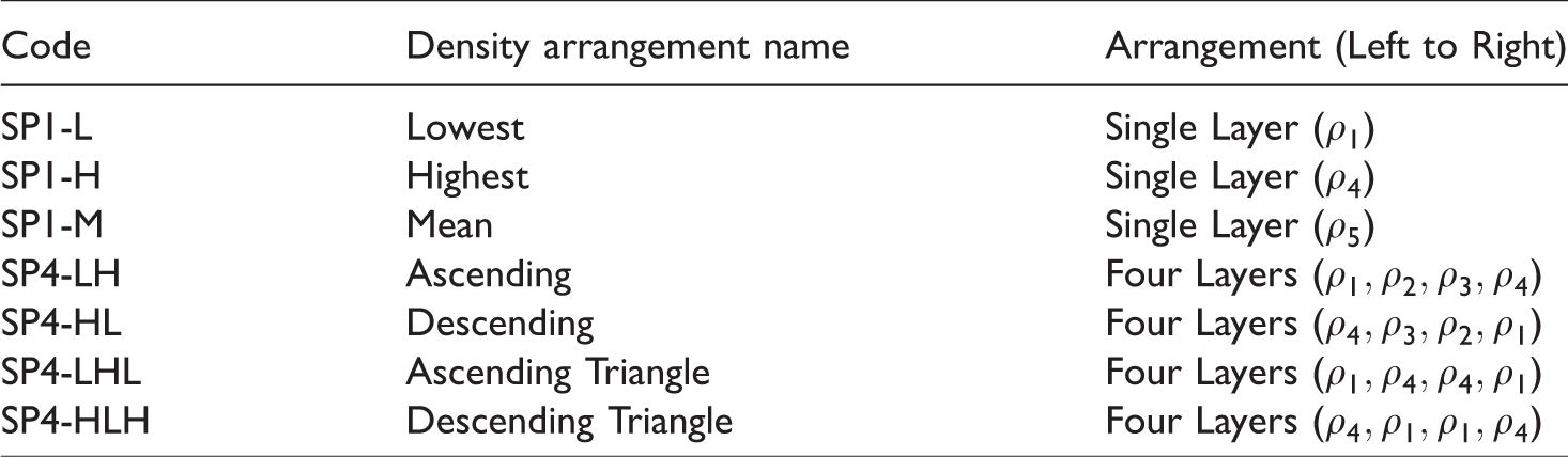
In the samples code, SP stands for the Sandwich Panel and the rest of the letters represent the type of arrangements. The numbers 1 and 4, which come after SP, represent the number of core layers. As an example, SP4-LHL represents the sandwich panel with a four-layer core and ascending triangle density arrangement.
After designing the structures, an epoxy adhesive was used to bond the sandwich structure components together. Six samples were fabricated for each structure type, and totally 42 samples were fabricated. Some of the panels are shown in Figure 6.
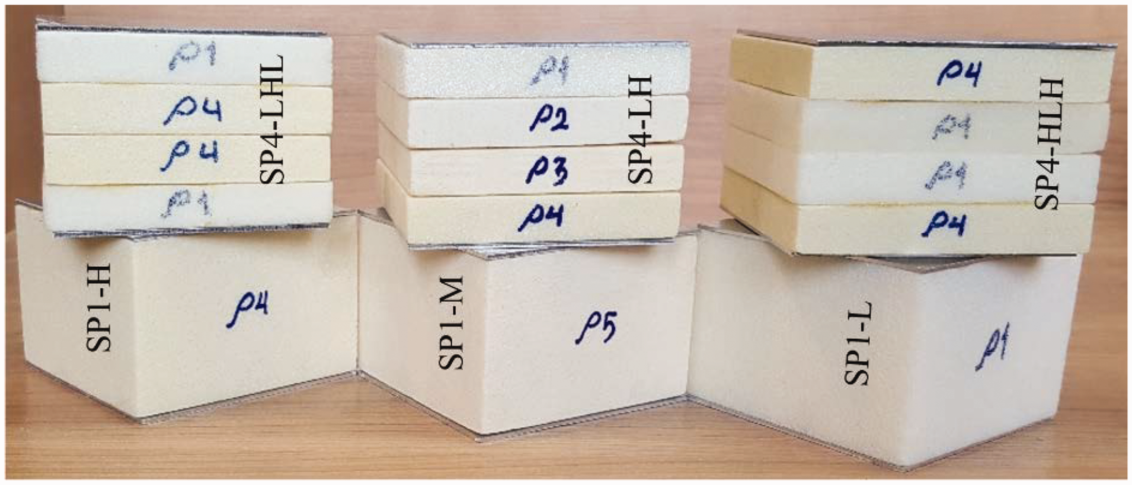
A number of sandwich panel samples with aluminum face-sheets and foam core (single layer and four layers).
Test apparatus
High-velocity impact tests were performed using a one-stage gas gun. This machine consists of a pressure vessel to compress the gas, two pressure gauges, launching barrel, fixture, two velocity meters and ballistic paste (Figure 7).
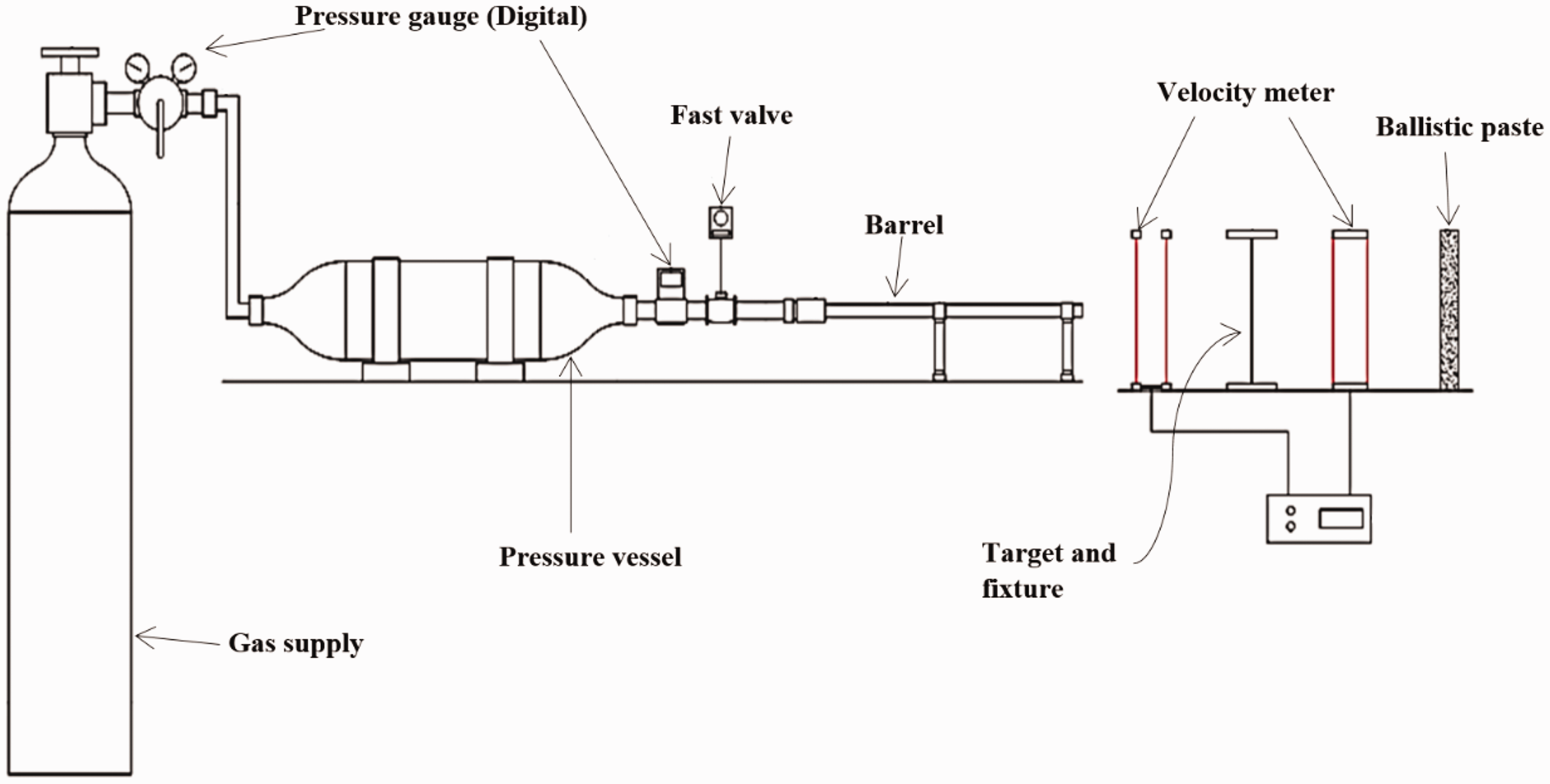
Schematic of one-stage gas gun.
High velocity impact test
First, the sample is placed in the corresponding fixture that is in front of the launching barrel, so that the edges of the sample are fully clamped (Figure 8). Second, the projectile and sabot are placed in the launching barrel and the gun reservoir is filled with air or argon gas to the desired pressure. Then, the projectile is fired immediately by opening the valve on the outlet of the gas. The projectile impact velocity with the target and the projectile residual velocity after leaving the target are recorded by two velocity meters.
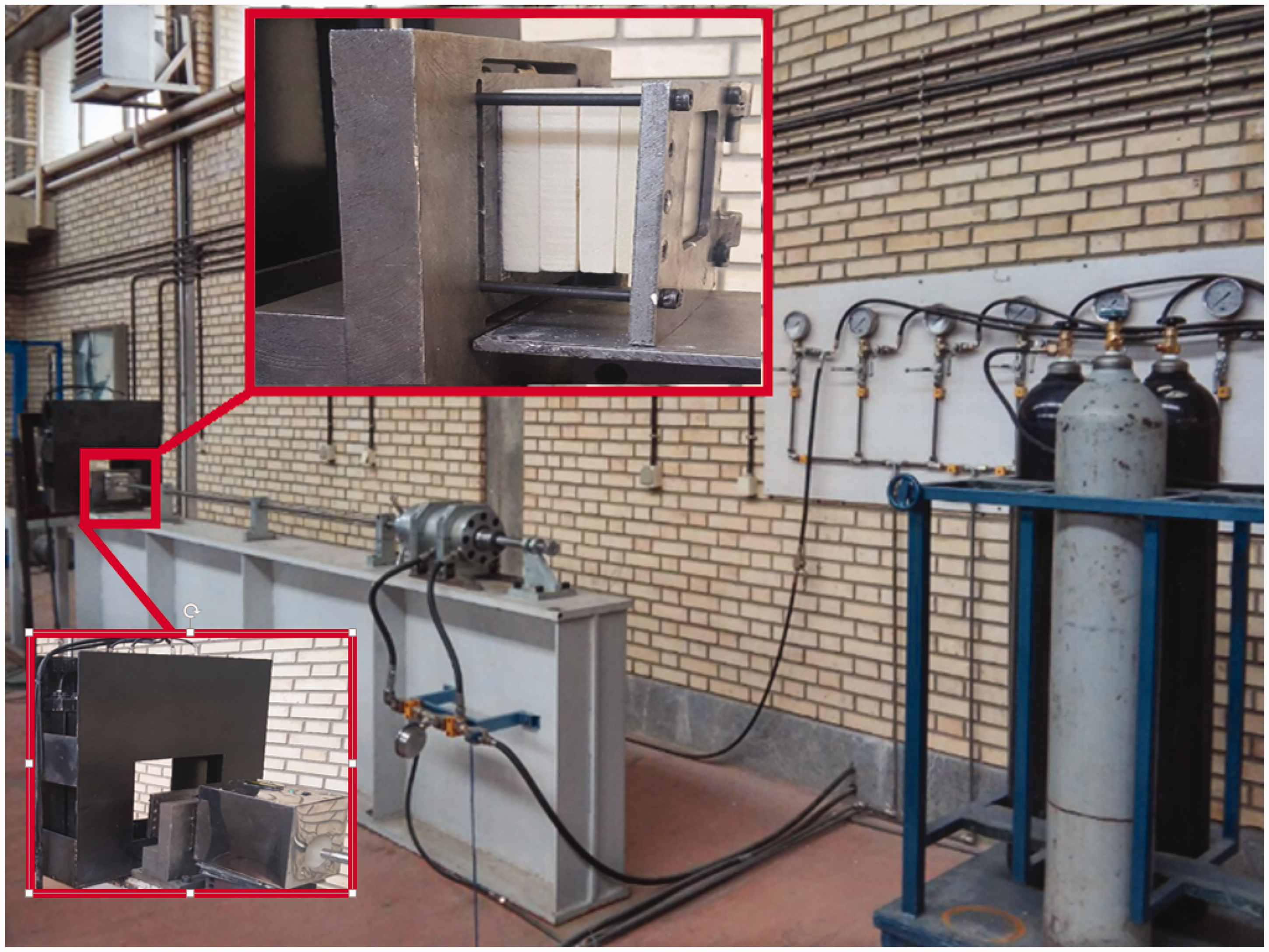
One-stage gas gun and the fixture.
Results and discussion
Ballistic limit velocity curve
In order to obtain the ballistic limit velocity of each structure, high-velocity impact test should be performed at least six times at different impact velocities on six samples. The impact velocities must be selected in such a way that the projectile surely passes through the target and leaves it, so by plotting the projectile impact velocities vs. residual velocities diagram and fitting the Jonas-Lambert relation (1) to them, the ballistic limit velocity of the panel can be obtained.

In equation (1),
The ballistic limit curves for all of the sandwich structures with one-layer and four-layer cores are plotted in Figure 9, and the results of this diagram are summarized in Table 4.
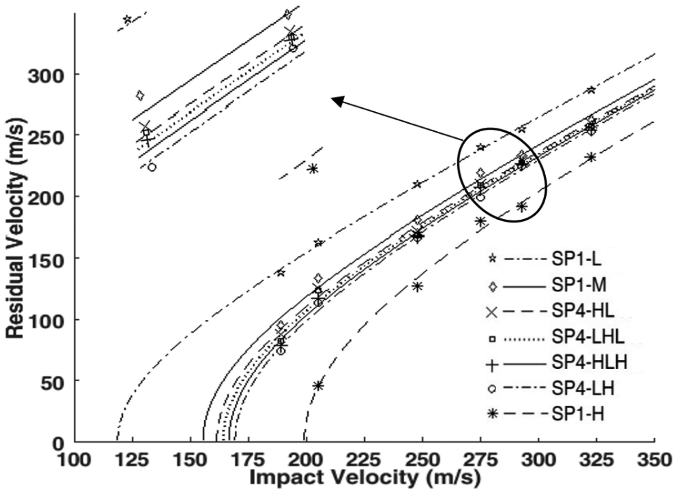
Ballistic limit curves of sandwich structures.
Ballistic limit velocity of sandwich panels.
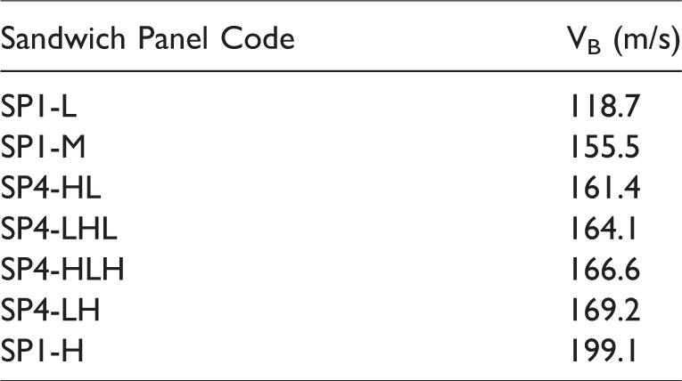
Overall, Figure 9 implies that

In the following, the parameters of the projectile impact velocity, core density, and core layering are investigated.
Parametric study
Effect of the impact velocity
As shown in Figure 9, for all structures, with decrease in the projectile impact velocity, the residual velocity of the projectile also decreases. This process is linear in the high velocities compared to the ballistic limit velocity and is nonlinear in the velocities near to the ballistic limit, i.e. as the impact velocity approaches to the ballistic limit velocity, the residual velocity of the projectile undergoes a larger amount of reduction. The amount of friction force applied to the projectile can be one of the reasons for this event. The slower the projectile is, the longer the friction force is applied to the projectile.
Effect of core density
According to Figure 9 and Table 4, comparing the ballistic limit velocity of the sandwich panels SP1-L, SP1-M and SP1-H together, it can be seen that increasing the core density increases the ballistic velocity so that with a 270% and 540% increase in the core density relative to the lowest density, the ballistic limit velocity increased by 31% and 67.7%, respectively. As shown in Figure 9, the ballistic limit velocity of the SP1-H and SP1-L structures, in contrast to the other sandwich structures with equal mass, is much larger and smaller, respectively, indicating that the structure mass has a significant effect on ballistic resistance. Obviously, the denser the material, the more the resistance is for the projectile to penetrate and consequently the more energy is absorbed.
Effect of the layering of the core and the layer arrangements
Four sandwich structures with four-layer cores and a single-layer core sandwich structure (SP1-M) with equal mass and volume were considered, and their ballistic limit curves are shown in Figure 9. Comparing the ballistic limit velocity of these structures, it can be concluded that the ballistic limit velocity of the structures SP4-HL, SP4-LHL, SP4-HLH, and SP4-LH was 3.8, 5.5, 7.1 and 8.8%, respectively, more than the ballistic limit velocity of sandwich structure SP1-M; i.e. all four-layer structures showed more ballistic resistance than the single layer core sandwich panel SP1-M. This result shows that layering of the core (considering the mass and the volume to be invariant) increases the ballistic limit velocity. Also, in four-layer structures comparing to each other, the SP4-LH structure showed the best and the SP4-HL structure showed the worst ballistic performance. The penetration procedure and the face-sheets deformation are the reasons for this event, which are expressed in later sections. Also, in SP4-LH structure, the lower layers are denser, so each layer is well supported by the next layer.
Target damage
After performing high-velocity impact tests, it was found by measuring the diameter of the hole in the front and back face-sheets that in most cases the diameters of the holes are similar and the same as the diameter of the projectile, while the diameter of the back hole is slightly larger than the diameter of the projectile. By examining the samples, three types of failure mechanisms that consist of plugging, petaling and dishing were observed (Figure 10). Each of these failure mechanisms absorbs energy from the projectile. Petaling absorbs more energy than plugging because there is more deformation in petaling and consequently more energy is needed to create this deformation. Regarding dishing failure, the larger the dish diameter, the larger the deformation and consequently the more energy is absorbed.
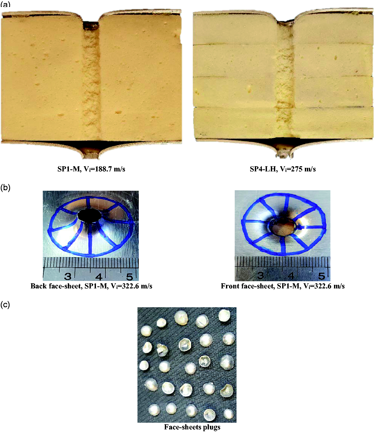
(a) Section samples, (b) front and back face-sheets of the sandwich structures and (c) separated plugs after impact.
Petaling and plugging
In general, the front face-sheet damage conditions are similar for all sandwich structures with four-layer and single-layer cores. The damage mechanism for the front face-sheet in all samples is shear plug and for the back face-sheet, and it can be a shear plug or petaling. The back face-sheet damage mechanisms for all sandwich structures at the impact velocity of 205 m/s are shown in Figures 11 and 12.
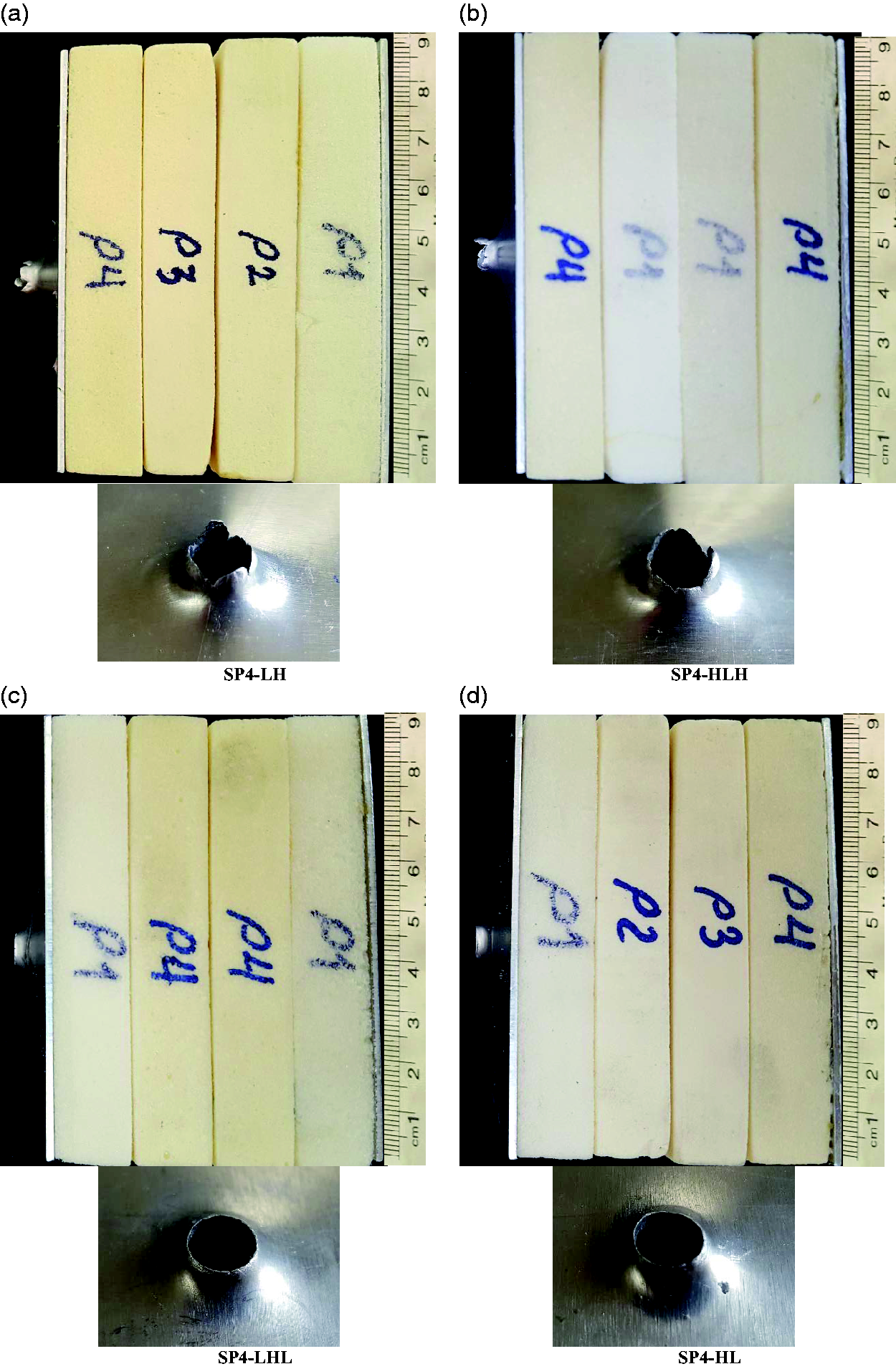
Side view and back face-sheet damage area of the four-layer core sandwich structures at the impact velocity of 205 m/s.
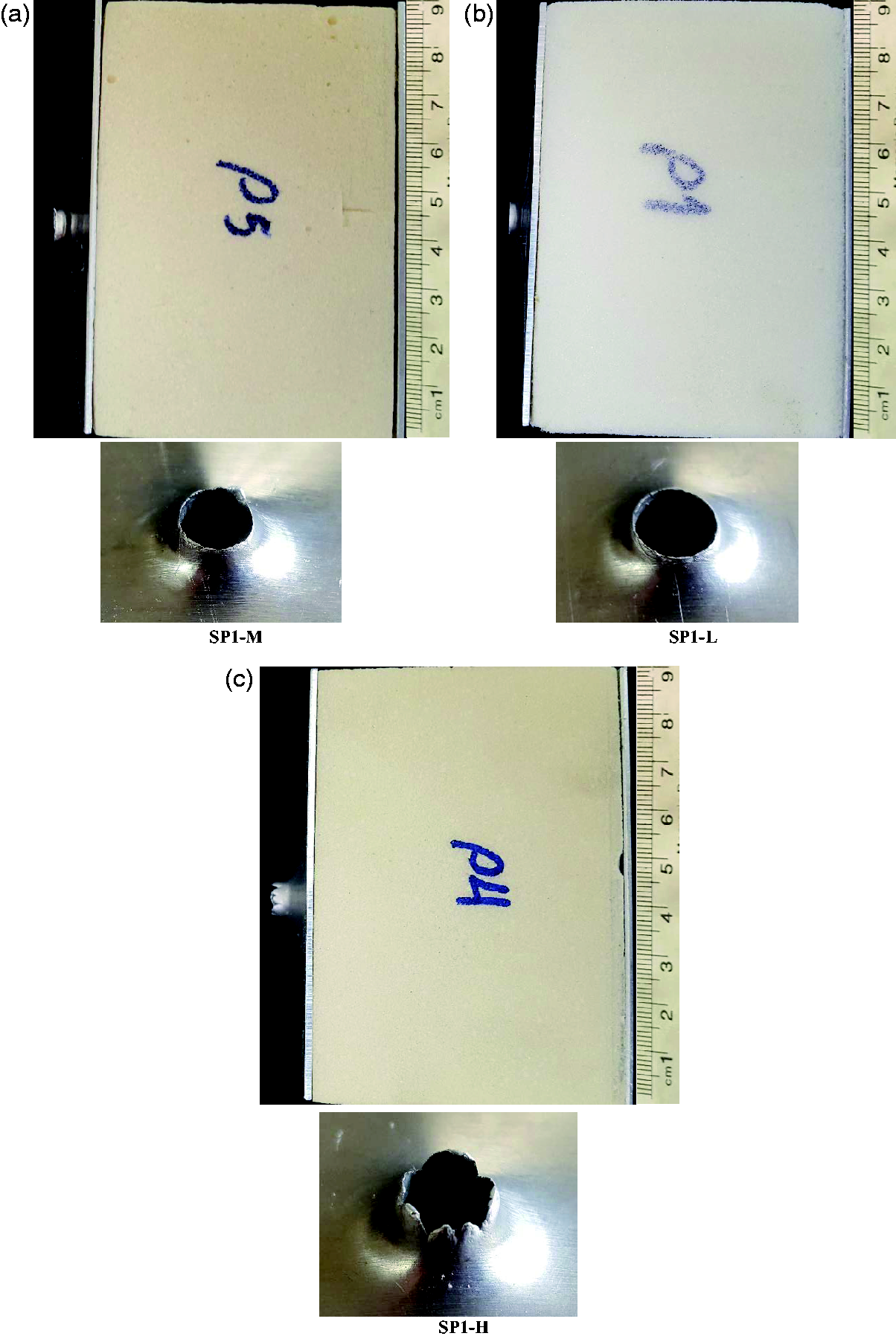
Side view and back face-sheet damage area of the single-layer core sandwich structures at the impact velocity of 205 m/s.
By observing the back face-sheet damage mechanism in four-layer core structures, it can be concluded that the back face-sheet of the structures with the highest density layer sticking to it experiences petaling deformation, and the back face-sheet of the structures with the lowest density layer sticking to it experiences plugging deformation. The penetration procedure is one reason why the residual velocity differs in different structures by the assumption of invariant mass and volume, and also why petaling and plugging deformations happen. For example, when a projectile penetrates a structure with the four-layer core of descending triangle arrangement, it first hits the denser layer and during the penetration process the layers become softer (the density and elastic modulus reduce), so the separated particles from upper layers penetrate to lower layers easily. As a result, when the projectile reaches the back face-sheet, it has a more direct contact with the face-sheet, i.e. the surface of the projectile’s contact and its constituent separated particles is smaller with the back face-sheet, which makes the applied force more concentrated and subsequently the back face-sheet undergoes less deformation and makes a shear plug. But in the case of ascending density arrangement, the projectile enters the denser layers from the less dense layers. Thereby, the separated particles from the softer layers cannot penetrate to denser layers and either stay beneath the projectile and move with it or part of them go aside around the projectile. Eventually, when the projectile reaches the last layer, the separated plugs are compressed together and have neither the ability to penetrate into the other layers nor the time to go aside, and this prevents the projectile from having a direct contact the back face-sheet, i.e. the contact surface of the projectile and its associated particles increase with the back face-sheet and the applied force distributes on a bigger surface. As a result, the deformation of the back face-sheet occurs with a larger radius, and the projectile passing area undergoes a deformation of the petal form. It should be noted that in this layer arrangement more energy is absorbed from the projectile, so the back face-sheet got enough time to undergo the petal deformation.
In sandwich structures with a single-layer core, the back face-sheet of SP1-H structure deformed in the petal form and the back face-sheet of SP1-M and SP1-L deformed in the shear plug form. Also, as observed in Figure 12, the number of the petals in the SP1-LH structure is more than the petals formed in other structures which indicate the energy absorption of this structure is more than the six others.
At the impact velocity of 322.6 m/s, the back face-sheet of all seven structures deformed in the shear plug form, because the high velocity prevents the back face-sheets from having enough time to make deformation in the form of petaling.
Dishing
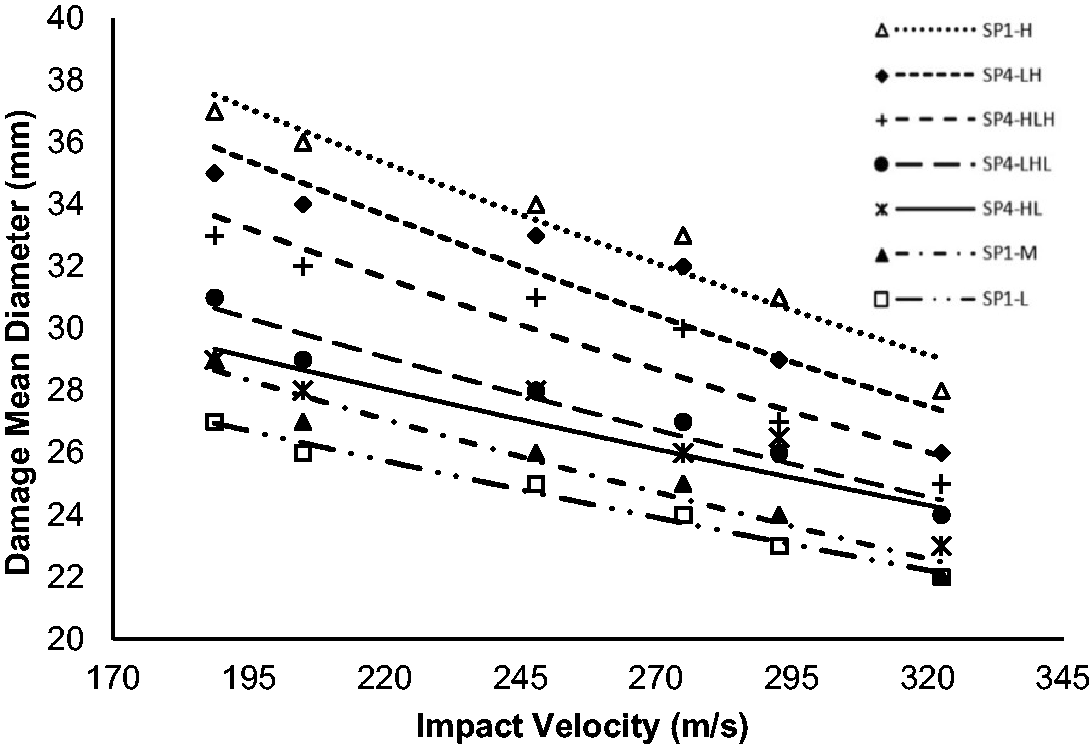
Dishing of the area around the impact location is another failure mechanism, which occurred after the projectile passing through the back face-sheet of the structures. This phenomenon can be seen in the samples section view in Figure 10. The method used to obtain the diameter of this failure is as follows: at first, the back face-sheet should be carefully separated from the sandwich structure, then using the paint thinner, the adhesive and foam remnants attached to the surface are removed to be a smooth one. The next step, a thin paper was well attached (not the paper should be pulled from all sides) to the back face-sheet on the sink side. Then, a soft black pencil was pressed uniformly on the paper to make a hachure. The hachure is bold in the areas which the face-sheet has no deformation, and there is a pale hachure on the paper for the areas that there is an indentation on the face-sheet. Thus, by measuring the mean diameter of the pale hachure area, the diameter of the back face-sheet damage is obtained (Figure 13). The results are shown in Figure 14, after the damage area diameter was measured for all samples. As it can be seen for all structures, by increasing the impact velocity, the damage diameter undergoes a reduction trend. As an instance, in the SP4-LH structure, with an increase in the initial impact velocity from 188.78 to 322.62 m/s, the diameter of the damaged area (dishing area) decreased by 34.6%; the back face-sheet has less time for deformation as the impact velocity increases. Another point is that by comparing all of the structures to each other, it can be concluded that the more ballistic resistant the structure has, the larger the damage radius of the back face-sheet is. For example, among the structures with similar mass, according to Figure 14, the diameter of the failure area of the SP4-LH structure is bigger than the diameter of the failure area of the rest of the structures, and as represented in Table 4, this structure showed better ballistic resistance. The diameter of the failure area of the SP4-LH structure is 23.9% larger than the SP1-M structure. In general, comparing the damage area diameter for all structures, it is concluded that

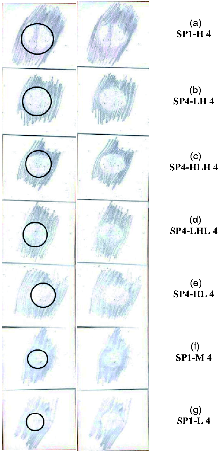
Papers with hachure for each of the seven types of sandwich structures at a speed of 275 m/s.
Mean diameter of damage area of all structures vs. impact velocity.
Conclusion
In this research, the penetration of cylindrical projectiles with hemispherical nose in seven types of sandwich structures with single-layer and four-layer foam cores is investigated experimentally. The effect of foam core layering and layer arrangements on the ballistic resistance of sandwich structures with multi-layer core was investigated and compared with the ballistic resistance of sandwich structures with a single-layer core. Also, damage mechanisms of structures were studied. The results showed that the impact velocity of the projectile, the arrangements of the layers and the core density played a significant role in the ballistic resistance of the structures. A summary of the most important results of this research is as follows:
The ballistic limit velocity of the structures compared in this study is as follows:
From the comparison of structures with a single-layer core, it can be concluded that increasing the density of the core increases the ballistic velocity in the sandwich structures so that by increasing the density of the core by 270% and 540%, the ballistic limit velocity is increased by 31% and 67.7%, respectively. The ballistic limit velocity of SP1-H, SP4-LH, SP4-HLH, SP4-LHL, and SP4-HL are respectively 28%, 8.8%, 7.1%, 5.5% and 3.8% more and the ballistic limit velocity of the SP1-L structure is 23.7% less than the SP1-M structure. In structures with the same mass, the layering of the core increased ballistic resistance. The SP4-HL structure has the lowest ballistic resistance among the four-layer core structures but is still better than the SP1-M structure and the SP4-LH structure showed the best ballistic resistance. By measuring the diameter of the hole created in the front and back face-sheets, it was found that in most cases the diameters of these two holes are similar and the same as the diameter of the projectile, while the diameter of the back face-sheet hole is slightly larger than the diameter of the projectile. In general, the failure mechanism for the front face-sheet in all specimens was a shear plug, and for the back face-sheet, it was either a shear plug or petal. Structures with highest-density foam sticking to the back face-sheet have a deformation of the petal type. For the projectile impact velocity of 322.6 m/s, the back face-sheet deformation of all structures was a shear plug. The diameter of the failure area for the back face-sheet of sandwich structures has an inverse relation with the impact velocity increasing, i.e. by increasing the impact velocity, the failure area diameter is decreasing. In general, by comparing the diameter of the failure area for all structures, it is found that:


Footnotes
Declaration of Conflicting Interests
The author(s) declared no potential conflicts of interest with respect to the research, authorship, and/or publication of this article.
Funding
The author(s) received no financial support for the research, authorship, and/or publication of this article.