
Abstract
Modern aircraft employ the use of lightweight engineering materials such as sandwich composites to increase the flexural rigidity of their structural components. These sandwich composites are limited by their low interfacial strength between the outer facesheets and internal core, which can result in facesheet-core debonding at relatively low out-of-plane loads. In this study, sandwich composites that are reinforced with through-the-thickness stitching are considered. Stitched sandwich composite specimens, fabricated from 110 kg/m3 perforated foam core with cross-ply carbon/epoxy facesheets, were manufactured with different combinations of stitch densities (0.0016–0.01 stitches/mm2) and linear thread densities (400–1200 Denier) of through-the-thickness reinforcement. Single cantilevered beam (SCB) tests were performed to characterize the facesheet-core debonding within the stitched sandwich composites. Unique fracture morphologies were observed that exhibit dependency on stitch processing parameters. A discrete cohesive zone modeling approach is used to simulate the separation of the facesheet from the core. Three-dimensional finite element analysis reveals crack curvature near the stitching. Good agreement between predicted and experimental measurements were obtained.
Introduction
Interlaminar strength of sandwich composites can be increased by incorporating through-the-thickness reinforcements such as stitching or z-pinning. Sandwich composites are widely used for their superior flexural rigidity due to their material architecture, which is composed of outer, rigid facesheets and a lightweight internal core. However, these composites are limited by their low interlaminar strength between the two constituents. Through-the-thickness stitching of sandwich composites with an internal foam core has shown to minimize facesheet-core debonding1–3 and improve load-carrying capability.4–8
The stitching process involves sewing polymeric threads through the thickness of a dry carbon preform at orthogonal or oblique angles7–9 using an industrial or robotic sewing machine. The processing parameters, such as the number of stitches per unit area (stitch density), the mass per unit thread length (linear thread density), thread material and finish, stitch distribution, pattern, pretension, and the stitch architecture, influence the properties and mechanical performance of these composites. The two primary parameters that have been shown to influence the out-of-plane performance of composite materials are stitch density and linear thread density.1,2 It has also been shown that stitching does not significantly contribute to the overall part mass (∼1% increase) of a sandwich composite. 10 Traditional damage modes of foam core sandwich composites subjected to impact also appear to be absent when these structures are reinforced with through-the-thickness stitching. 6 In stitched sandwich composites subjected to low-velocity impact, the primary form of failure is stitch-matrix column buckling and delamination of the topmost surface. Stitched regions subjected to impact have also been reported to undergo larger regions of core cracking when compared to their unstitched counterparts. 11
Simulating delamination of unstitched composite laminates is typically performed by using a cohesive zone modeling approach. In unstitched composites, cohesive elements or contact surfaces are incorporated between plies to simulate delamination. The cohesive material behavior is defined by a traction-separation law, which describes the micromechanical damage process that occurs at the interface. For an unstitched composite laminate, a bilinear traction-separation law (Figure 1) is commonly assumed and is primarily associated with small-scale bridging conditions. This model is described by three parameters: the critical strain energy release rate, the maximum traction stress (σ1), and a penalty stiffness (Knn). Damage occurs during the linear softening region (
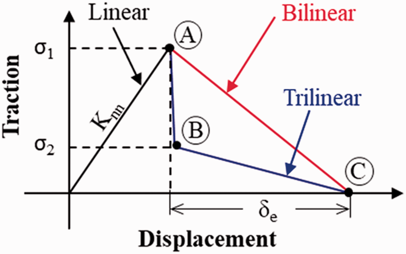
Traction-separation laws to describe brittle cohesive behavior.
In stitched composites, an increase in the strain energy release rate during crack propagation may occur due to the through-the-thickness reinforcement. Under mode I conditions, the stitching bridges the opposing crack faces and induces traction stresses to resist crack growth. Therefore, a bilinear traction-separation law is not appropriate due to large-scale bridging conditions that may be present. Under large-scale bridging conditions, the shape of the cohesive law for the through-thickness reinforcement is needed to capture the failure mechanisms near the delaminated interface. 12 Ranatunga and Clay 13 assumed a linear softening law (bilinear traction) to represent the failure process of a z-pin cohesive zone under mode I conditions. The evolution of damage was predominately due to frictional sliding of the z-pin near the delaminated interface, which is characteristic of a bilinear traction-separation law. The pullout process of the through-thickness reinforcement is mechanically stable. However, this traction-separation response may not be true for z-pins subjected to in-plane shear near the delaminated interface or for other types of through-the-thickness reinforcements.14,15 For stitched samples, instability may occur in the traction-separation response during mode I and mode II separation and can yield sharp decreases in the traction stresses. 16
The selection of the shape of the cohesive law for stitched composites is determined by performing interlaminar tension13,16–19 and interlaminar shear tests
20
of a single through-thickness reinforcement. The traction-separation law can also be determined using a J-integral approach
21
and by superposing bilinear cohesive laws to represent multiple damage mechanisms.
12
Moreover, interlaminar tension tests of stitched composite laminates have revealed that the traction-separation law is a trilinear shape,16,18,22 as shown in Figure 1. The trilinear traction-separation law represents the interaction between different damage mechanisms of the through-thickness reinforcement,
23
and is dictated by a relatively linear material response, which consists of a maximum traction stress (Point A), followed by a sudden decrease in the penalty stiffness that represents fiber failure. Subsequently, large-scale fiber bridging is obtained and represented by a linear softening phase (
Linear and nonlinear spring elements have been widely used by researchers to represent the failure process of the through-the-thickness reinforcements during composite delamination.17,22,24–27 The material behavior of the spring element is typically dictated by the load-displacement response obtained from interlaminar tensile or shear tests. For example, Tan et al. 18 incorporated experimental load-displacement measurements from interlaminar tension tests as the constitutive behavior for nonlinear spring elements in a cohesive zone finite element model (FEM) of a stitched double cantilevered beam (DCB) specimen. Reasonable agreement between experimental measurements and predicted results was achieved. An alternative approach is to represent through-the-thickness reinforcements as discrete cohesive zones, where two cohesive zone laws are employed to represent the delamination resistance of the unstitched and stitched regions. This allows the microscale damage mechanisms to be better represented near damage sites, rather than being localized within beam elements that are not connected to internal plies. Encouraging results from several researchers have been obtained.13,28,29
In this study, two-dimensional (2D) and three-dimensional (3D) finite element analyses (FEAs), simulating the facesheet-to-core separation process in stitched single cantilever beam specimens, was performed. The facesheet-to-core separation and failure of the through-the-thickness stitching are represented using discrete cohesive zones using a bilinear and trilinear traction-separation law, respectively. A sensitivity analysis is conducted on the components of a unique trilinear traction-separation law that represents the bridging behavior of through-the-thickness reinforcements using 2D FEA. The facesheet-to-core separation is then modeled using 3D FEMs using a discrete cohesive zone modeling approach. Validation of the models is performed by comparing load and crack growth predictions to experimental measurements from previous studies.30,31 The fabrication, computational, and experimental approaches are discussed in the following sections.
Materials and fabrication
Single cantilever beam (SCB) specimens were fabricated from an infused epoxy/carbon fiber sandwich composite panel with 110 kg/m3 foam core. The core was perforated manually in a 6.35 mm grid spacing with a 0.79 mm diameter needle to allow the resin to perfuse through the core during infusion. The carbon/epoxy facesheets were comprised of a cross-ply layup configuration [0°/90°/90°/0°]3. A crack initiator made from Teflon™ film of thickness 0.0127 mm and length 76.2 mm was placed between the facesheet and the core. The dry sandwich composite preforms were stitched using a 2000H Juki industrial sewing machine using a modified lock stitch architecture. A Vectran™ thread was selected based on previous studies22,32 and based on material availability. A 10 mm distance was maintained between the initial crack length and the first row. The 2.25 mm diameter needle was used to stitch the dry preforms and was selected based on robotic stitching processes.
32
A range of stitch densities (
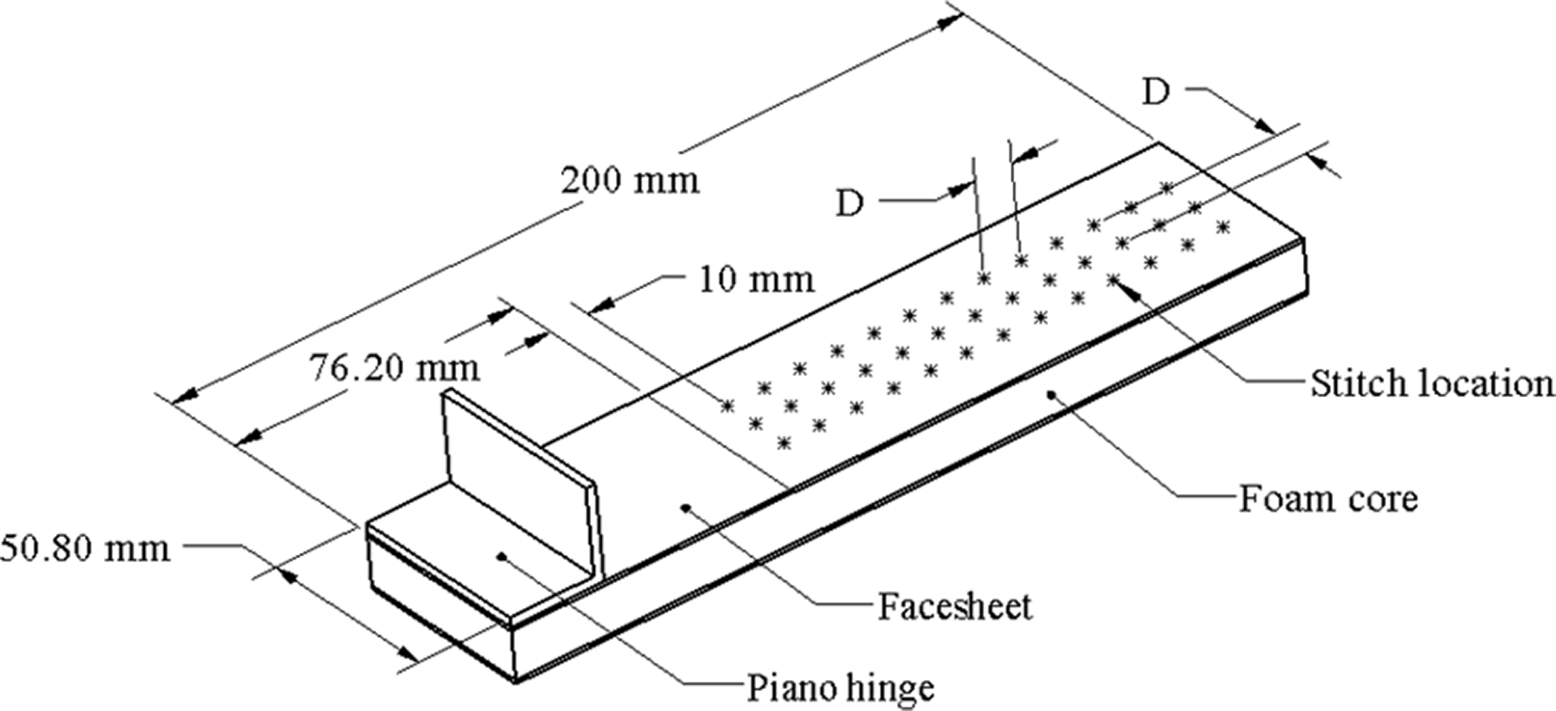
Schematic of a single cantilever beam (SCB) specimen.
Single cantilever beam (SCB) test procedure
The SCB tests were conducted in accordance with the specimen sizing and test standards proposed by Ratcliffe and Reeder. 34 A displacement rate of 0.5 mm/min was applied to the SCB specimens. 35 The bottom surface of the SCB specimen was rigidly constrained with a non-rotating base. The test fixture with a specimen under load is shown in Figure 3. A 1-kN load cell and a linear variable displacement transducer were used to measure the reactive load and applied displacement, respectively, at 1 Hz sampling frequency. Visual measurements of the crack length were quantified using an ARAMIS digital image correlation system. A total of three replicates were performed for each specimen configuration.
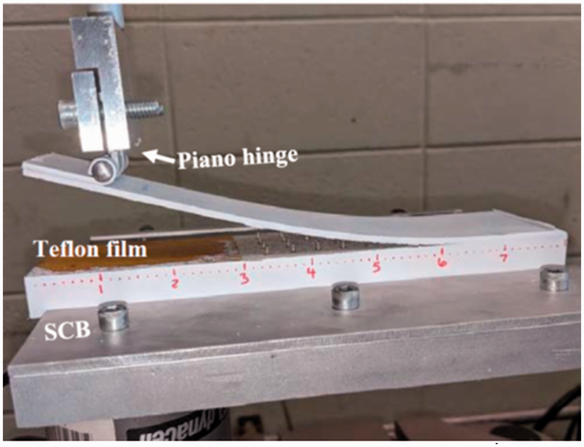
Single cantilever beam test setup.
Numerical modeling approach
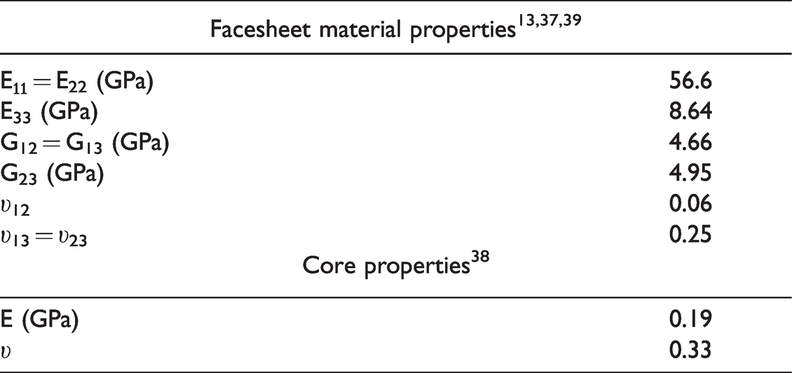
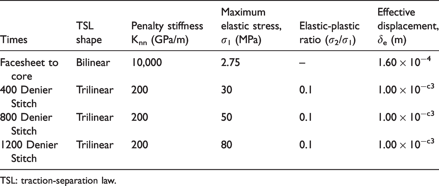
Implicit FEA of stitched SCB specimens was performed using ABAQUS 2019 commercial software. A 2D analysis was performed to assess the influence of a trilinear traction-separation law on the predicted load-displacement response. These results were then used to inform a 3D FEM using a discrete cohesive zone methodology to evaluate the influence of stitch parameters on the crack growth behavior. The facesheet and core interface was discretized to independently simulate the debonding of the foam core from the facesheet and failure of the through-the-thickness reinforcement near the delaminated interface. The material properties used in the FEMs are summarized in Table 1. In the following sections, the 2D and 3D finite element analyses are discussed.
Two-dimensional finite element analysis
The 2D FEM is shown in Figure 4. The bottom surface of the SCB model is rigidly constrained for all degrees of freedom and a displacement of 50 mm was directly applied above the partially debonded region. An element mesh size of approximately 0.15 mm was used near the cohesive interface. The cohesive surface is discretized into three zones 13 : 1) initiation, 2) facesheet-to-core interface, and 3) an area to represent stitching, as shown in Figure 4. The relative cohesive zone of the stitch row is approximately 2 mm and based on physical measurements of the stitch column diameter. At the facesheet-to-core interface (unstitched regions), a bilinear traction separation law was assumed to represent the unstable behavior at crack initiation. A fracture energy of 220 J/m2 was used in the unstitched regions and was obtained from a previous study. 2
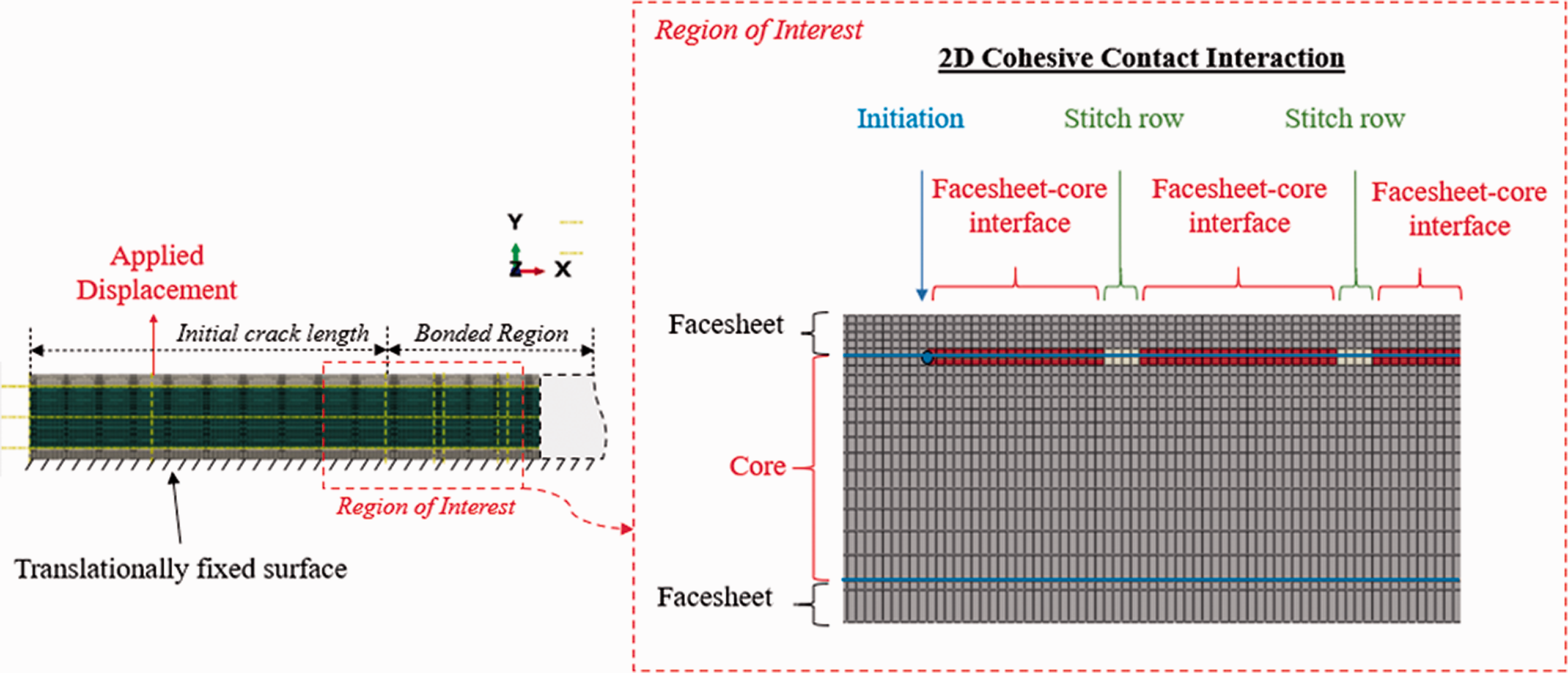
Two-dimensional FEM to simulate crack growth in stitched sandwich composites.
In this study, a trilinear traction-separation law is used to represent the bridging behavior of the through-thickness reinforcements in stitched sandwich composites based on an assumed shape from interlaminar tests. 16 A sensitivity analysis of the stitch trilinear traction-separation law on the load-displacement response of an SCB specimen was performed. The influence of the cohesive stiffness (K), maximum elastic stress (σ1), effective bridging displacement (δe), and bridging stress (σ2) are shown in Figure 5(a) to (d), respectively. Table 2 gives the nominal cohesive parameters used to represent each interface. The trilinear traction-separation law for the stitched region has an initial linear-elastic material behavior, followed by a sharp reduction after the maximum elastic stress to a known bridging stress (Figure 1). The traction stress then decreases linearly from the bridging stress, where cohesive failure occurs when the traction stresses are zero at the maximum effective displacement. The ratio of the maximum elastic stress to known bridging stress is denoted as the elastic-plastic ratio (σ1/σ2). It is important to note that the area under of the curve of the stitch traction-separation law was not held constant in order to evaluate the influence of each parameter independently. This is unorthodox as compared to traditional cohesive zone modeling approaches, where the area under of a bilinear traction-separation law is assumed to be constant in order to determine the effective displacement by varying the maximum elastic stress.
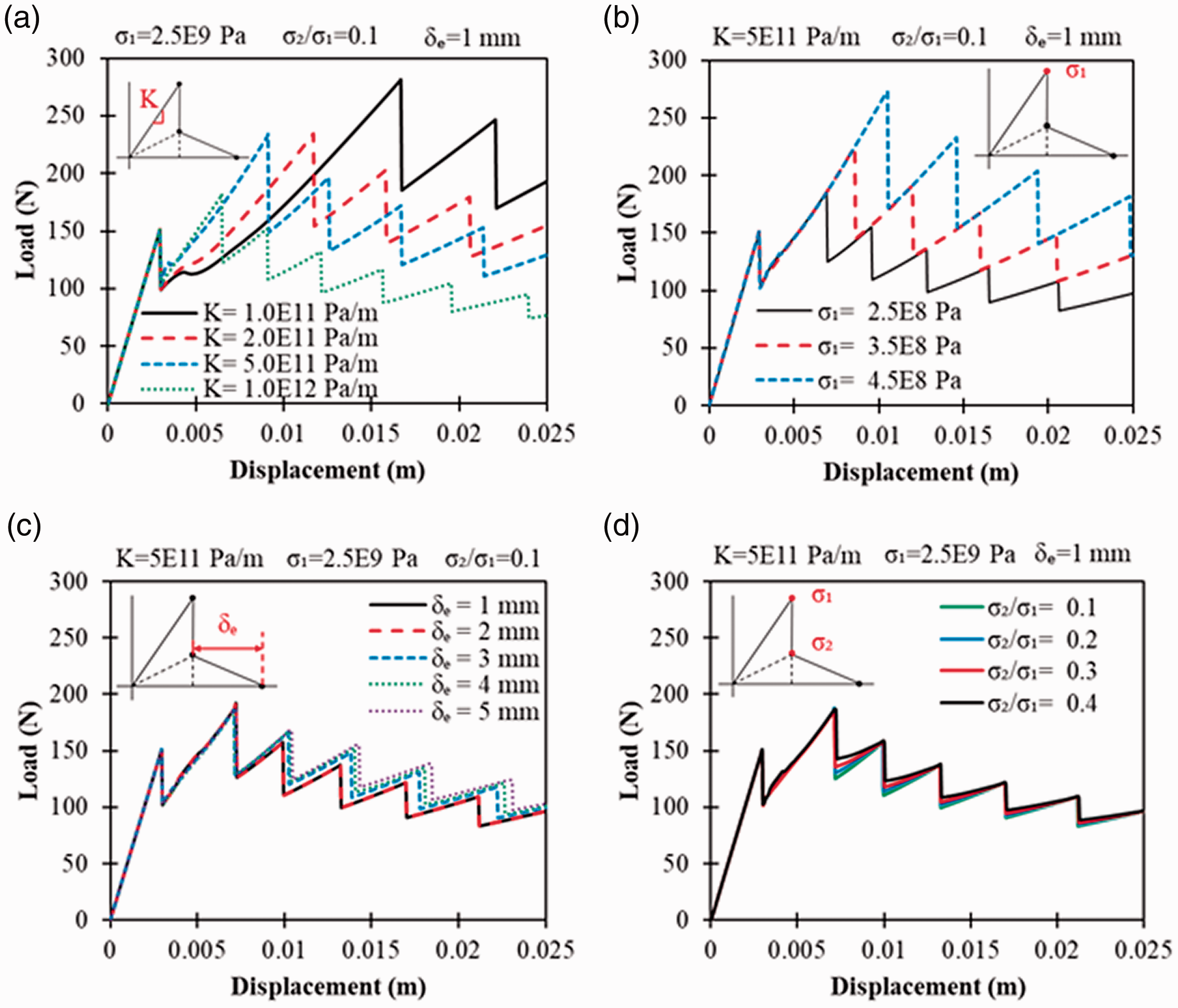
The influence of (a) cohesive stiffness, (b) maximum stress σ1, (c) effective displacement δe and (d) the elastic-plastic ratio (σ2/σ1) on the load-displacement response.
Nominal cohesive parameters of the of the 2D FEM.
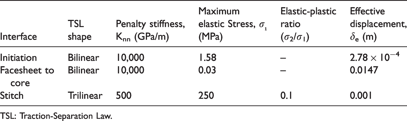
TSL: Traction-Separation Law.
The load as a function of the applied displacement for select cohesive stiffnesses (K = 1, 2, 5, and 10 × 1011 Pa/m) is shown in Figure 5(a). Decreasing the mode I stiffness of the cohesive traction-separation law increases the magnitude of the maximum load required to fail the stitch rows. For high cohesive stiffnesses (5 × 10¹¹ < K ≤ 5 × 10¹² Pa/m), the measured load increases linearly until failure of the initial stitch row. As a note, very high cohesive stiffnesses (>1013) may yield spurious results and inaccurately represent the traction-separation behavior during the delamination process. Additionally, premature separation between the facesheet and core may occur beyond the initial stitch row if the cohesive stiffness of the through-thickness reinforcement is too low (K < 2 × 10¹¹ Pa/m). As a result, greater applied displacements are necessary to reach the failure load of the more ductile cohesive interface. This behavior indicates that ductile through-the-thickness reinforcements with high tensile strengths can be beneficial in resisting delamination in polymer composites.
The influence of the maximum elastic stress on the load-displacement response of a stitched sandwich composite is shown in Figure 5(b). Increasing the maximum elastic stress from 250 MPa to 450 MPa linearly increases the maximum load required to fail initial and subsequent stitch rows. Additionally, no significant change in the stiffness (slope) of the load-displacement response is observed. The load as a function of the applied displacement for select effective displacements is shown in Figure 5(c). As expected, the bridging behavior of the cohesive interface only influences subsequent stitch rows after the initial stitch row has failed. Increasing the effective bridging displacement of the trilinear traction separation law increases the applied displacement and load magnitude required to fail subsequent stitch rows. Furthermore, increasing the effective displacement from 1 mm to 2 mm does not show any difference in the predicted response. This is primarily attributed to the spacing of the through-the-thickness reinforcements. Decreasing the spacing may likely develop greater large-scale bridging and increases in the load-magnitude response. Lastly, increasing the ratio of the bridging stress to the maximum elastic stress (σ1/σ2) after damage initiation does not globally affect the magnitude of compliance or maximum stitch failure loads, as shown in Figure 5(d). The primary influence is associated with the difference in the magnitude of load before and after stitch failure. Increasing the elastic-plastic ratio decreases the load difference during stitch failure, prior to frictional sliding of the through-thickness reinforcement.
Based on the observations revealed by altering the four parameters (cohesive stiffness, maximum elastic stress, effective displacement, and bridging stress), a systematic approach for determining the traction-separation law of a through-thickness reinforcement can be determined. The two primary parameters that influence the load-displacement response are the maximum elastic stress and the cohesive stiffness, which can be altered to appropriately predict crack growth within stitched sandwich composites. In this study, the elastic-plastic ratio is assumed to be approximately 0.1. An effective bridging displacement of 1 mm is used in this study, which is based on interlaminar tensile tests of a single stitch. 16 The cohesive stiffness is increased or decreased to match the stiffness (slope) of the experimentally measured load-displacement values obtained from SCB testing. Further increases or decreases in the effective displacement can alter the magnitude of the load to predict the desired load-displacement response and crack growth behavior.
Three-dimensional finite element analysis
The 3D FEM used to simulate separation between the facesheet and core is shown in Figure 6. Three different stitch densities (0.0016, 0.0057, and 0.01 stitches/mm2) corresponding to 2, 3, and 4 stitches, respectively, across the specimen width were considered. Incompatible hexagonal elements were used to improve the deformation gradients within the domain of the element when the test article is subjected to bending. Symmetry boundary conditions were imposed to decrease the computational time. A small-time increment, damage stabilization parameter, and a dissipated energy fraction of 10−30 s, 10−4, and 0.004, respectively, were used to achieve convergence. To improve computational efficiency, unstable crack growth between the facesheet and core at initiation was not simulated. A bilinear traction-separation law representing the facesheet-to-core interface was used, and a fracture energy of 220 J/m2 with a maximum traction stress of 2.75 MPa was applied. The traction-separation laws used to represent the micromechanical damage process of stitching with different linear thread densities (400, 800, and 1200 Denier) are shown in Figure 7. The cohesive parameters used to represent each interface is shown in Table 3. A cohesive stiffness of 200 GPa/m for the through-the-thickness reinforcements was assumed and iteratively determined based on a sensitivity analysis, which is discussed in the following section. The maximum elastic stress was iteratively determined by comparing it to load-displacement measurements obtained from SCB tests. The bridging stress and effective displacement after stitch failure were assumed to be 0.1 of the maximum elastic stress and 1 mm, respectively, based on interlaminar tensile tests obtained from.16,17,22
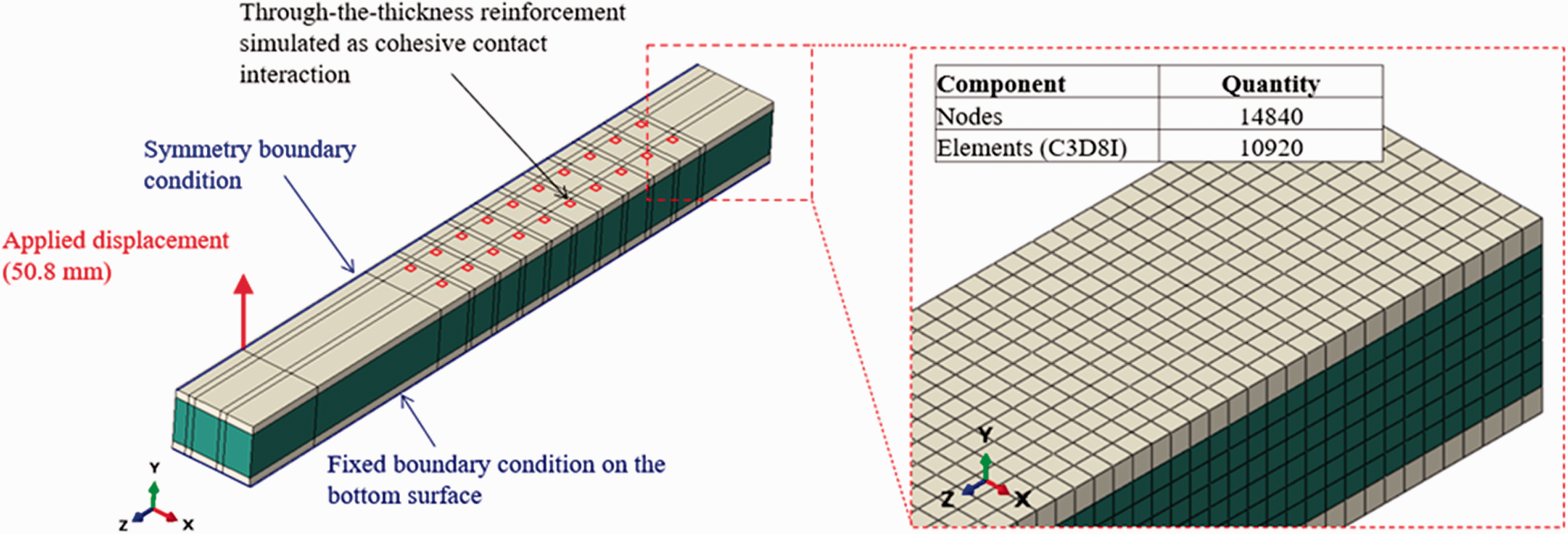
Three-dimensional FEM to simulate crack growth in stitched sandwich composites.
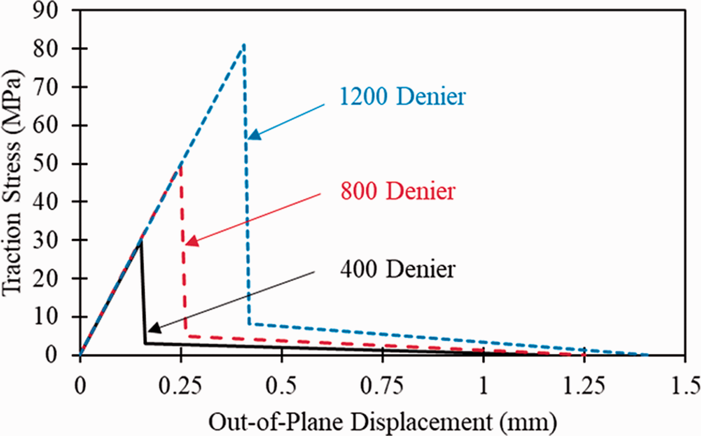
Traction-separation laws to represent stitching of different linear thread densities.
Cohesive parameters of the of the 3D FEM.
TSL: traction-separation law.
A systematic approach for determining the traction-separation law for through-thickness reinforcements is used for stitched sandwich composite laminates that contain different stitch densities and linear thread densities. A comparison of the predicted and experimental values of the load and crack length for SCB specimens containing select stitch densities (0.0016, 0.0057, and 0.01 stitches/mm2) is shown in Figure 8(a) and (b). As mentioned previously, unstable crack propagation is observed at crack initiation, which results in a sharp decrease in the reacted load. Correspondingly, an increase in the measured crack length is observed. The reacted load then increases linearly as the crack front approaches the initial stitch row. Upon failure of a stitch row, the crack front immediately progresses to the adjacent stitch row. Sharp decreases in the measured load were observed as subsequent stitch rows failed. The magnitude of the failure load at each stitch row decreased with an increase in the applied displacement. This behavior is due to a greater distance between the location of the reacted load and crack front, which decreases with each subsequent failure of a stitch row. Increasing the stitch density from 0.0016 stitches/mm2 to 0.01 stitches/mm2 proportionally increases the maximum load prior to failure by approximately 48% and decreases the crack growth by approximately 16%.
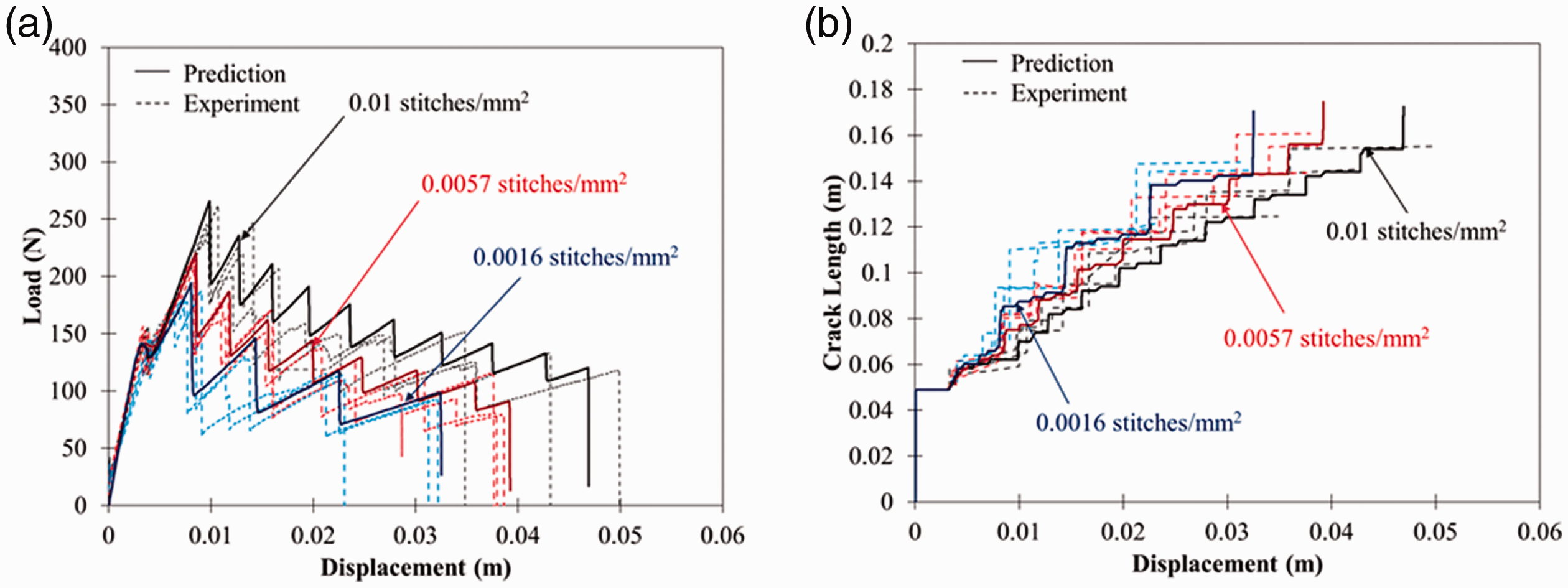
Influence of stitch density on the (a) load and (b) crack growth response.
The influence of select linear thread densities (400, 800, and 1200 Denier) on the load and crack growth of an SCB specimen is shown in Figure 9(a) and (b). Increasing the linear thread density from 400 Denier to 800 Denier increases the maximum load at which stitch failure occurs by approximately 18%, but only a 6% decrease is realized in the measured crack lengths. At high linear thread densities (>1200 Denier), the crack lengths decreased by approximately 14% to 30%. The greater reduction in crack growth is mainly attributed to a change in the fracture morphology, as shown in Figure 10(a) and (b). Primarily, stitch pullout from the facesheet was observed for low linear thread densities (400 Denier). At high linear thread densities (1200 Denier), stitch-column pullout and foam core failure were observed. 2 This change in fracture morphology results in significantly greater capability to resist crack growth. Lastly, multiple stitch rows were observed to fail for high and low linear thread densities.
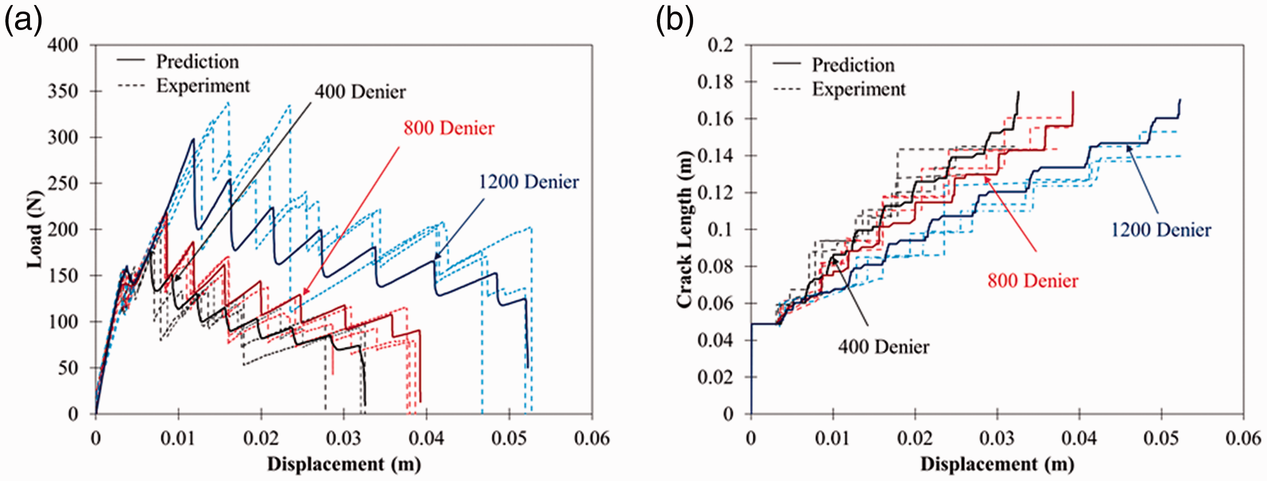
Influence of linear thread density on the (a) load and (b) crack growth response.
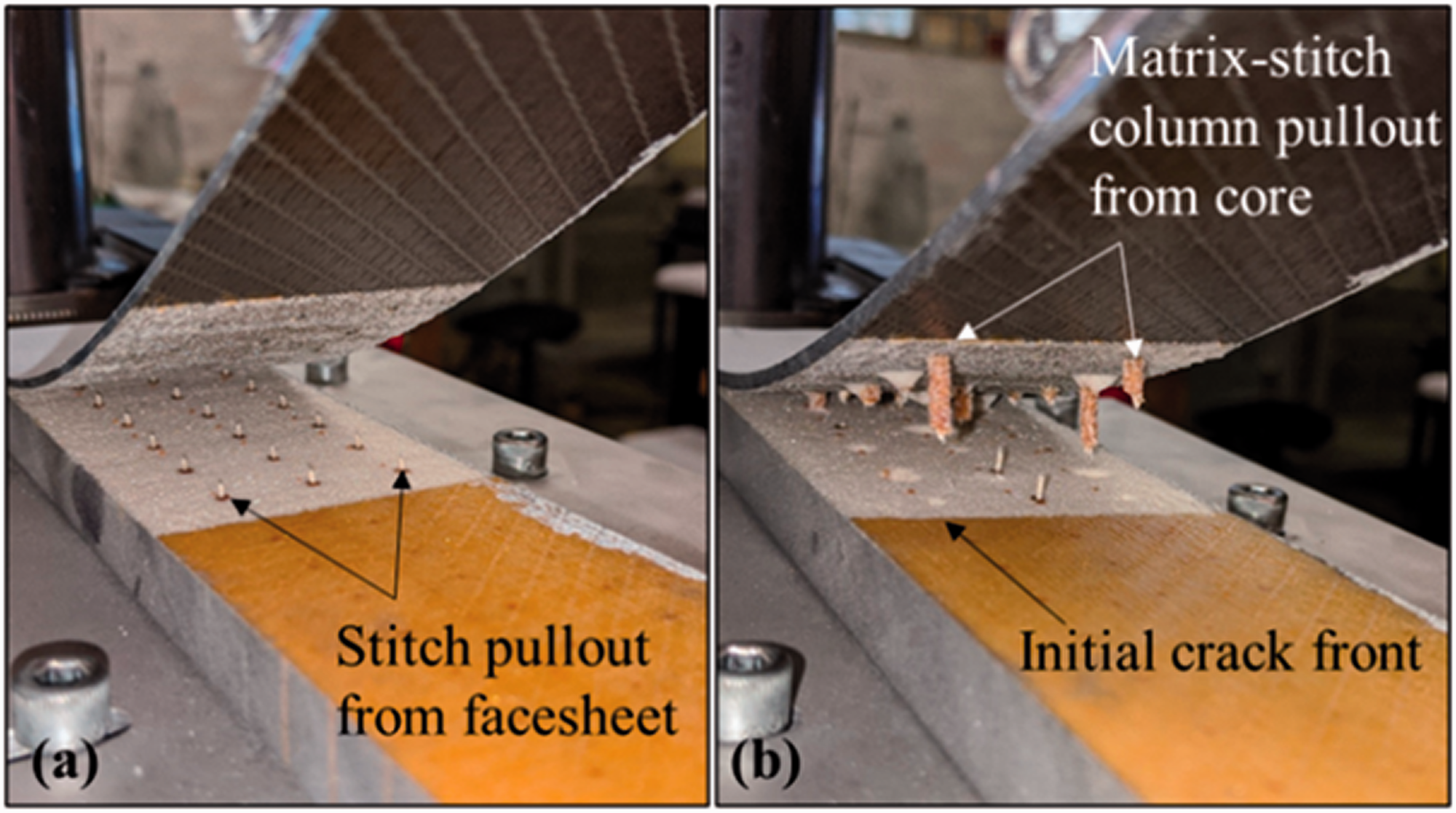
Fracture morphology during the facesheet-to-core separation of a sandwich composite stitched with (a) 400 Denier and (b) 1200 Denier Vectran™ thread.
The discrete cohesive FEM approach shows excellent agreement with the load and crack length measurements for each select stitch density (Figure 8) and linear thread density (Figure 9). In this approach, the traction-separation law for the through-thickness reinforcement was assumed to be the same for each stitch row. During some of the tests, the simultaneous pullout of the through-thickness reinforcements along a stitch row did not occur, which caused some discrepancy between the predicted and experimental results, as shown in Figure 9(b). This behavior may occur due to the misalignment of the through-thickness reinforcement. Additionally, compaction of the structural threading can occur during the vacuum bagging process, which can distort the reinforcement in the through-the-thickness direction and result in a variation of the maximum elastic strength. These aforementioned effects induce changes in the applied displacement at which a stitch row failure occurs. Therefore, the load-displacement and crack-growth responses can appear shifted due to a variation in the traction-separation law of each through-the-thickness reinforcement. It may be more appropriate to use a stochastic finite element process to take in account the variation in the traction-separation response for various linear thread densities and stitch densities used in stitched sandwich composites.
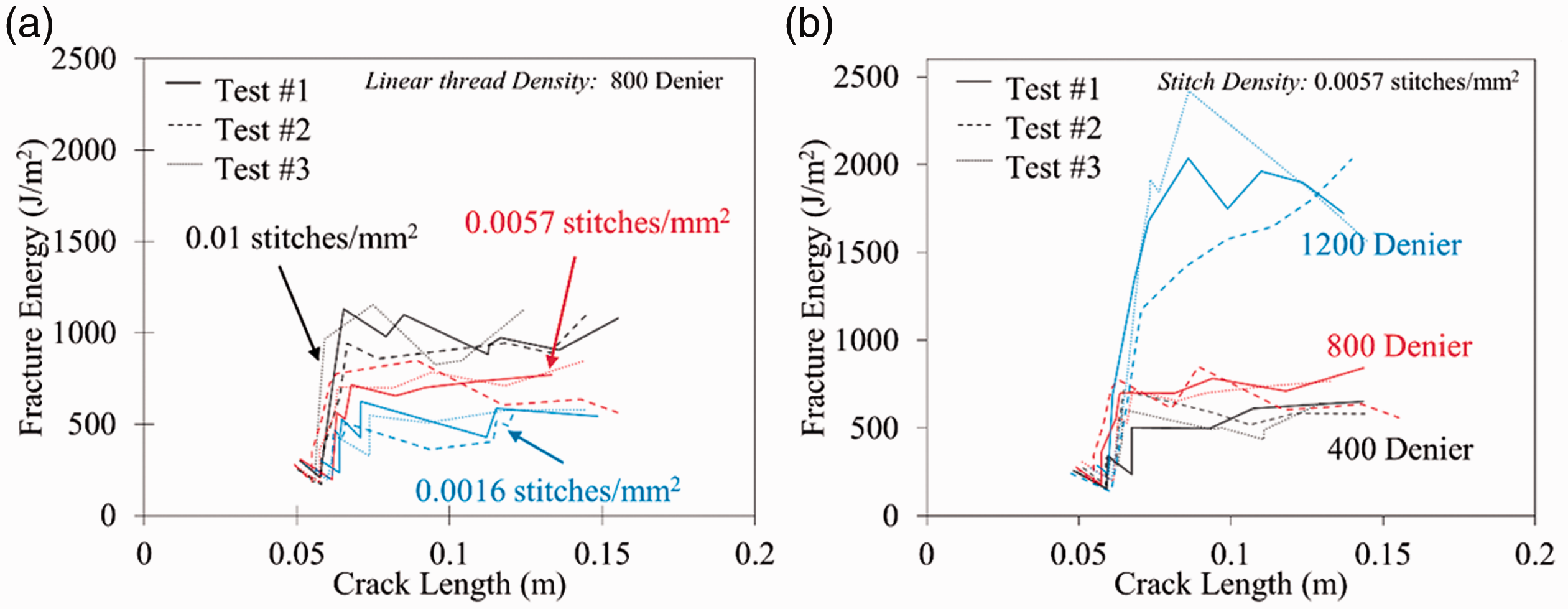
The fracture energy for select stitch densities and linear thread densities is shown in Figure 11(a) and (b), respectively. As a note, these fracture energy values and their analytical framework are based on previous studies.30,31 Increasing the stitch density from 0.0016 stitches/mm2 to 0.01 stitches/mm2 results in a proportional increase in the fracture energy. Furthermore, the fracture energies remain relatively constant as a function of crack length. The influence of linear thread density on the fracture energy is shown in Figure 11(b). Increasing the linear thread density from 400 Denier to 1200 Denier increases the fracture energy by approximately 900%.
Fracture energy as a function of crack length for select (a) stitch densities (0.0016–0.01 stitches/mm2) and (b) linear thread densities (400–1200 Denier).
The predicted crack front curvature along the specimen’s width for select loads and applied displacements is shown in Figure 12. The initial crack front curvature is straight along the specimen’s width prior to crack initiation (Region 1). As the crack propagates (Region 2), a variation in the growing crack front is observed due to the anticlastic curvature of the facesheet subjected to bending.40–44 This behavior is due to Poisson’s effect, which results in opposing concave and convex curvature along each side of the composite facesheet. Additional curvature in the crack front is observed as the crack front approaches the initial stitch row (Region 3). The through-thickness reinforcements locally constrain the facesheet to resist crack growth and result in some curvature in the crack front near the stitching. Crack front curvature appears to be dominated by the anticlastic deformation of the facesheet away from the through-thickness reinforcements. At the maximum applied load, the crack front moves beyond the initial stitch row (Region 4), which is followed by failure of the initial stitch row. Afterward, the crack front immediately propagates to the second stitch row and stitch bridging is observed (Regions 5–6).
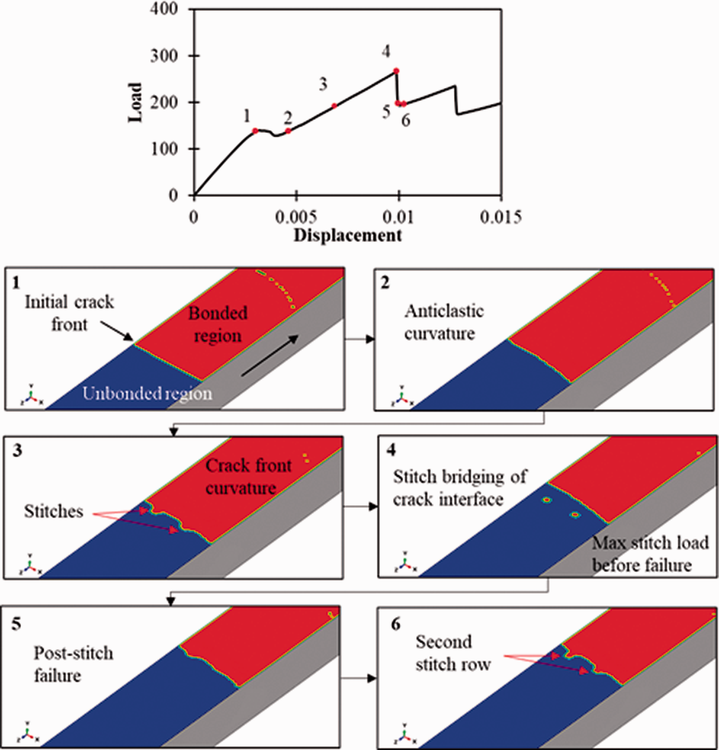
Crack front variation due to the presence of the through-thickness stitching.
Conclusion
A discrete cohesive zone modeling approach was used to simulate the mode I load and crack length response of stitched sandwich composites with select stitch densities (0.0016–0.01 stitches/mm2) and linear thread densities (400–1200 Denier). Single cantilever beam (SCB) tests were performed to determine the load and crack growth response as a function of the applied displacement. Experimental tests reveal unique fracture morphologies that are dependent on stitch parameters. Using low linear thread densities (400 Denier), stitch pullout from the facesheet near the facesheet-to-core interface was observed. However, matrix-stitch column pullout from the core was observed at the facesheet-to-core interface for stitched sandwich composites with high linear thread densities (1200 Denier) of Vectran™ thread.
In this study, a trilinear traction-separation law was used to represent the failure process of the through-the-thickness reinforcement within 2D and 3D FEMs. The 2D FEA revealed that the cohesive stitch stiffness and elastic maximum traction stress of the stitch are the primary parameters that influence the initial load-displacement response of an SCB test, whereas the bridging stress and effective displacement influenced the load-displacement response after the initial stitch row failure. The predicted load and crack length responses using a 3D FEM have good agreement with experimental measurements. However, the current approach does not consider the variation of the traction-separation law used to represent the through-thickness reinforcement. Variation in the maximum elastic stress, bridging stress, and effective displacement after stitch failure may occur due to misalignment, angle of the reinforcement, and stitch compaction that could occur during fabrication. The 3D FEM approach showed that crack fronts may be influenced by the through-the-thickness reinforcements and can lead to crack curvature along the specimen width. The methodology presented in this study provides a pathway to guide researchers on the selection of a trilinear traction-separation law that accurately represents the failure process of stitching during delamination events.
Footnotes
Acknowledgements
The authors are grateful for the many fruitful discussions and guidance from Dr. James Ratcliffe, NASA LaRC. The authors gratefully acknowledge the support from the Center for Advanced Vehicular Systems, the Raspet Flight Research Laboratory’s Marvin B. Dow Stitched Composites Development Center, and the High-Performance Composite Materials Laboratory.
Declaration of conflicting interests
The author(s) declared no potential conflicts of interest with respect to the research, authorship, and/or publication of this article.
Funding
The author(s) disclosed receipt of the following financial support for the research, authorship, and/or publication of this article: This work was supported by the Air Force Research Laboratory (Award no.: FA8650-19–2-2211).