
Abstract
In this study, various structural configurations such plain core, two-core, epoxy columns in the core, core stitched, and facesheet stitched were designed in the foam core sandwich composite with the aim to increase the absorbed energy and to decrease core/facesheet debonding area due to low-velocity impact. Glass fiber/epoxy and PVC foam were used as a facesheet material and a core material, respectively. The impact energy values were selected considering to penetration and perforation cases. The core stitching effect on low velocity impact behavior of sandwich composites were compared to facesheet stitching and it has been determined that the core stitching process can be an alternative to the facesheet stitching process in terms of the absorbed energy value. Impacted sandwich composites are investigated for core/facesheet debonding; the modifications through the thickness increased the failure path for core/facesheet debonding initiation and the results show that a significant decrease in the core/facesheet debonding area has been achieved.
Introduction
Sandwich composites are a type of multi-layered composite structures that generally consists of two thin facesheets and one thick core material between facesheets. This combination gives optimum specific mechanical properties. Facesheet materials have high strength, high modulus whereas core material has very low density. Facesheets carry bending, in plane loads and core material transfers transverse shear loads to facesheets. The facesheets (facings) are commonly made of aluminum or textile reinforcements. The core materials have alternatives e.g. Nomex, thermoplastic, aluminum honeycomb, foam, corrugated core, bio-inspired cores, etc. Sandwich composites behave just like I-beam under loading conditions. Sandwich composites are commonly used in many engineering applications. The cost, availability, usage area, lifetime loading, etc. criteria are considered at the material selection stage. For example, carbon-epoxy facings and aluminum or Nomex honeycomb, as core material, are typical sandwich materials in aerospace applications. Glass-epoxy or glass-vinyl ester are used in the facings of civil, marine, and wind blade sandwich structures, and foam or balsa materials are used as a core. Sandwich composites are very sensitive to impact loading. Because of the high strength difference between the facesheet and core material in the sandwich composite, core/facesheet debonding may occur during loading. Core/facesheet debonding may be invisible and will cause undesirable results. Impact damages can occur during the manufacturing and service life of composite structures. Hailstorms, runway debris, tool drops, collisions with animals or vehicles can cause this type of damage. These damages decrease load carrying capacity, structural stability, and the stiffness of the composite structure. The transverse stiffness of the impacted part specifies the damage size. The impact may leave little or no visible damage which is very difficult to inspect.1,2
In the previous studies, low-velocity impact response of foam core sandwich composites has been extensively studied experimentally. There have been many experimental studies on the effect of layered core materials and foam core material. The perforation energy and failure modes under the low-velocity impact of curved sandwich composites with layer-wise graded cores were examined experimentally. Also, foam with different densities were used; the use of different core layers increased the impact performance of sandwich composites. 3 The low-velocity impact response of sandwich composites consisting of two and three layers of foam core configurations was investigated experimentally; the core structure with three layers caused more energy absorption but and decreased maximum contact force value. 4 The experimental perforation resistance of sandwich structures made of same facesheets but core materials with different raw materials and/or densities were examined under low-velocity impact conditions; nine foams, based on a cross-linked PVC, a linear PVC, and PET, have been combined with thin glass fiber reinforced plastic skins and the effect of mode I and mode II fracture toughnesses on low-velocity impact were determined. 5 The effects of Balsa wood, PVC foam, and Ayous wood core materials on the low-velocity impact have been investigated; Ayous wood has higher mechanical properties but has the highest weight. 6 In sandwich composites for higher energy levels, core/facesheet debonding occurs between the bottom facesheet and core interface because of bending. It is seen that PVC core material has higher interface bonding compared to balsa. 7 Experimental investigation on the low-velocity impact response of carbon fiber laminates and sandwich composites has been investigated in terms of the effects of impactor mass, velocity, and different impact energy levels. Obtained results showed that the impactor mass affects damage area, failure modes, and absorbed energy value for equivalent energy levels. 8 In situ polymeric pins were manufactured for to investigate flexural and compressive properties. Pin diameter and distances highly effects core shear strength.9–11
There are some experimental studies on the core and facesheet parameters of foam core sandwich composites under impact loading. The effects of the core material and its thickness on the impact behavior were investigated; core material and core material thickness have significant effects on absorbed energy, penetration, and perforation threshold values. 12 The low-velocity impact test was performed on sandwich composites consisting of carbon fiber epoxy facesheet and foam core experimentally. Core thickness, facesheet thickness, and different types of core parameters were investigated; it is shown that facesheet has no significant effect but, core thickness, type and density have high effects on damage size. 13
There are a lot of studies on increased delamination resistance, load transfer, and distribution loads of composite materials. Some methods like using tough resins, adding nanoparticles, applying surface treatment parameters were not found to be sufficiently effective. 1 Yet through-the thickness reinforcement application has a significant effect on core/facesheet debonding. Stitching, z-pinning, tufting, and 3D weaving can be given as examples of through-the-thickness reinforcement. 14 To increase delamination resistance of laminated composites, stitching was applied in some studies. Quasi-static indentation test results showed that stitch density and stitch yarn thickness has a high effect on energy absorption and delamination. 15 The stitching process decreases delamination progression for carbon fiber laminates under in-plane loadings.16,17 Stitched glass fiber – polypropylene with sewing yarns, stitch orientations, and steps were investigated; obtained results showed that the through-the-thickness stitching process decreases the delamination area. 18 Tensile, bending, and low velocity impact tests were applied to stitched laminated composites; it is seen that stitching process improved mechanical properties. 19
The effect of stitching process on the performance of sandwich composites were studied. T-shaped sandwich composite joints were examined experimentally and analytically; through the thickness reinforcement was made by using the z-pinning process and with this application, fracture force and energy increased. 20 Pin reinforced sandwich composites were investigated for compressive and low velocity impact loadings. High improvement was achieved with pin.21,22 Compression properties of stitched lattice core were investigated experimentally; it was observed that the stitch yarns failed due to the fractures and debondings. 23 Through-the thickness reinforcement of sandwich composites on low-velocity impact was also investigated; the angle of stitching and step of stitching were examined. The higher density of stitches enhances absorbed energy value. 24 Impact tests of stitched sandwich composites at different energy levels were carried out experimentally; it is shown that stitched sandwich composite absorbs more energy and has better impact performance for the same energy level. 25
The stitching of sandwich composites was examined experimentally in terms of compression, shear, and bending properties. Stitch angle and step were used as the variable parameters. It is shown that the stitching increases the maximum stress value. 26 Tensile, compression, and shear tests were applied experimentally on non-stitched and diversified-angle-stitched sandwich composites. Obtained results showed that there is increase in strength of stitched sandwich composite with diversified angles compared to the unstitched sandwich composite. 27 In the earlier work, the effect of stitching yarn count on the compression, shear, and bending performances of composites was examined. It was found that increasing the stitch yarn count improves mechanical properties. 28 Another earlier work has shown that through-the thickness reinforcement increases tensile and compression properties of sandwich composites. 29 However, it is important to understand the effect of such reinforcements on the impact performances of sandwich composites. From the previously reported studies, the effect of stitching core and facesheet together on the impact performances was not studied.
In this study, various structural configurations such as plain core, two-core, epoxy columns in the core, core stitched, and facesheet stitched were designed in the foam core sandwich composite to increase the absorbed energy and to decrease core/facesheet debonding area due to low-velocity impact. Sandwich composites were manufactured with E-glass fiber and epoxy resin as a facesheet material and PVC foam as a core material, respectively. Therefore, the modifications through the thickness as core stitched, and facesheet stitched were applied. Sandwich composites with plain core, two-core, and epoxy columns in the core were also studied to compare the results. Contact force-time, contact force-displacement curves were plotted with obtained data. Peak contact forces, absorbed energies, displacements, contact times, and core/facesheet debondings were examined. Debonding between facesheet and core materials under the low-velocity impact was deeply investigated. 30
Material
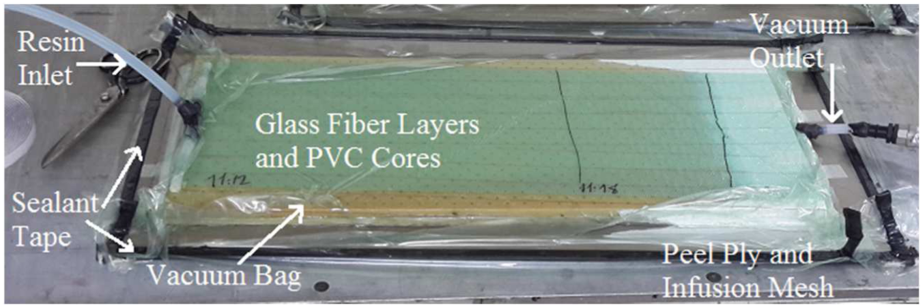
In this study, five types of sandwich composites were manufactured. The top view of stitched sandwich preforms was given in Figure 1. All of the sandwich composites were manufactured by vacuum-assisted resin infusion process as shown in Figure 2. The PVC foam core material is Airex C70.55 with 0.06 g/cm3 density and Momentive L160 epoxy resin and H160 hardener are used. As the facesheets, each sandwich composite consists of totally 12 unidirectional E-glass fiber layers and each layer has 300 g/m2 areal density. Top view of stitches before manufacturing for two-core sandwich preforms with cores stitched (2Scs) and factsheets stitched (2Sfs). Vacuum-assisted resin infusion process.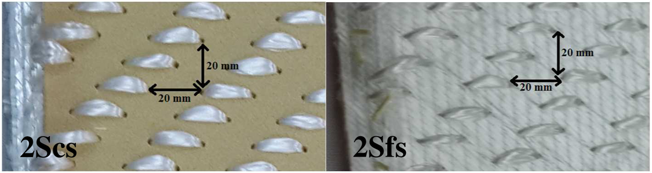
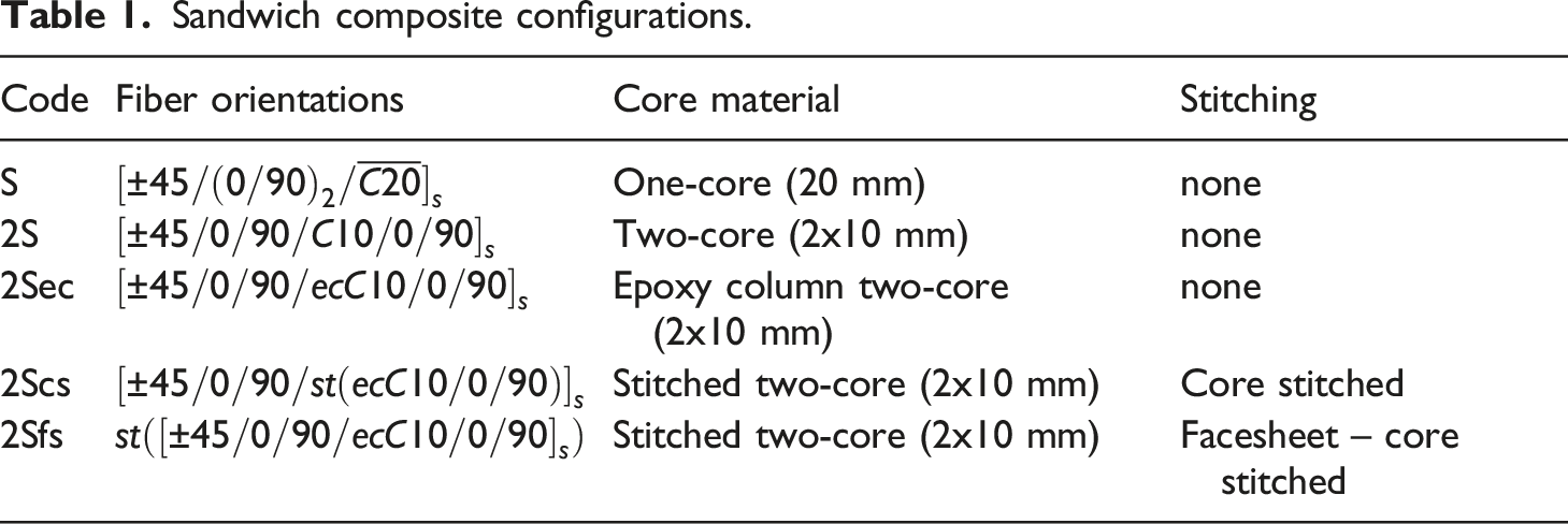
Sandwich composite configurations.
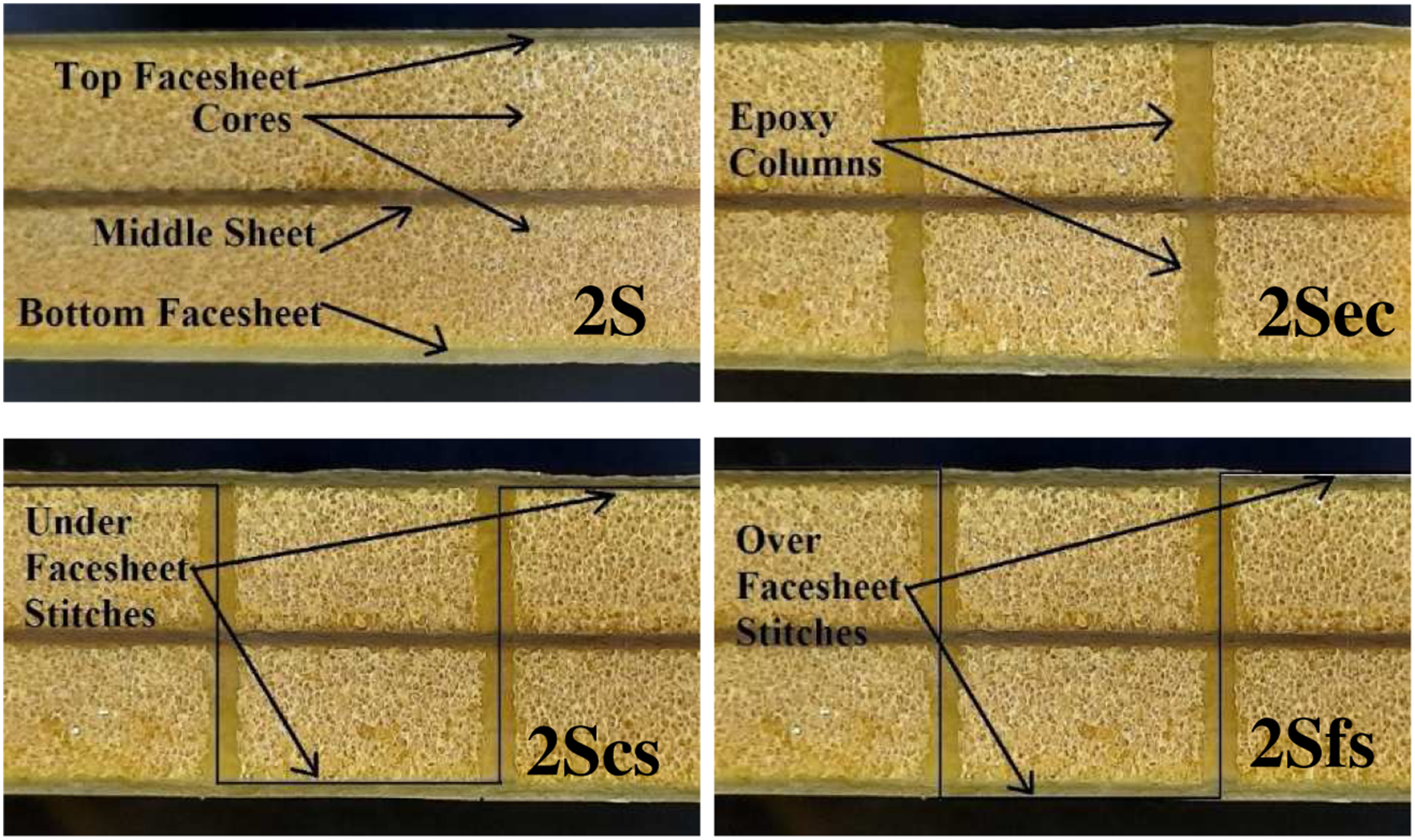
Cross-section views after manufacturing.
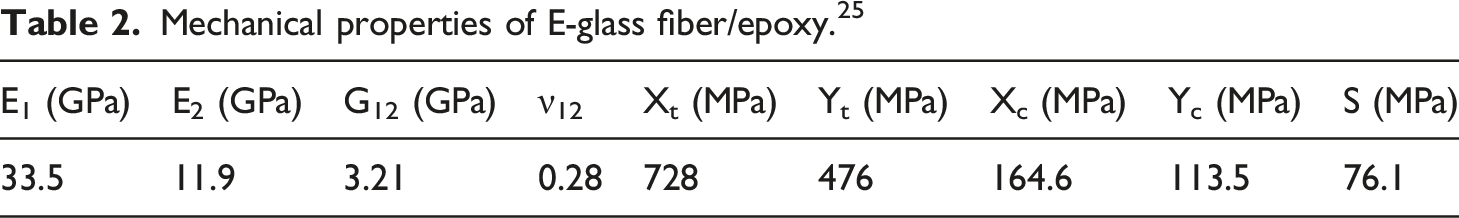
Mechanical properties of E-glass fiber/epoxy. 25
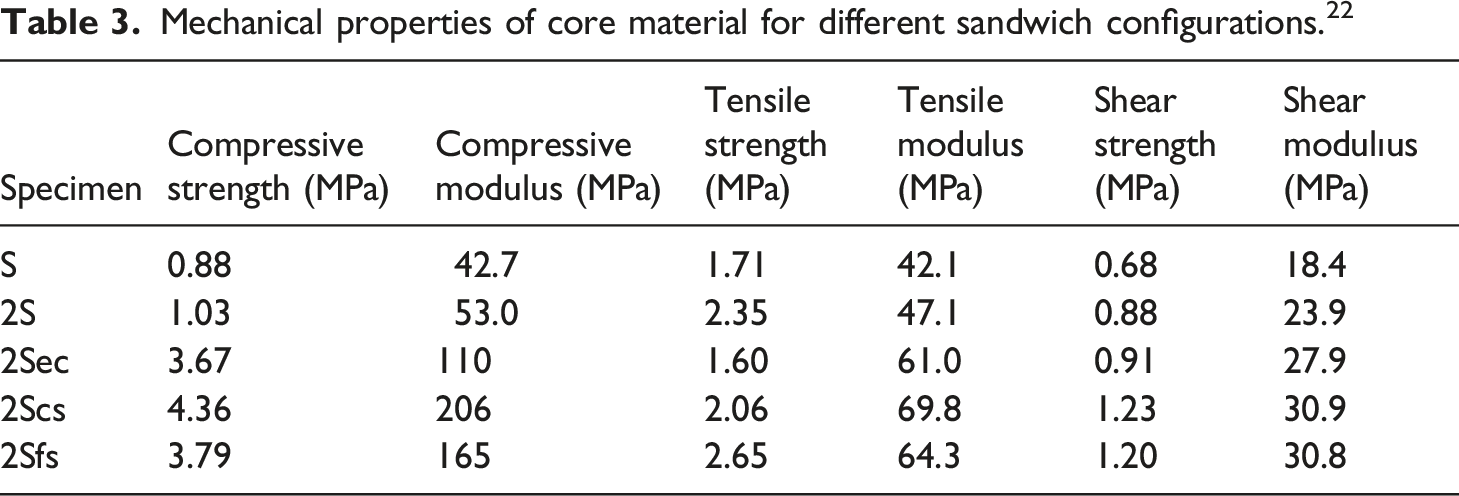
Mechanical properties of core material for different sandwich configurations. 22
Low-velocity impact test
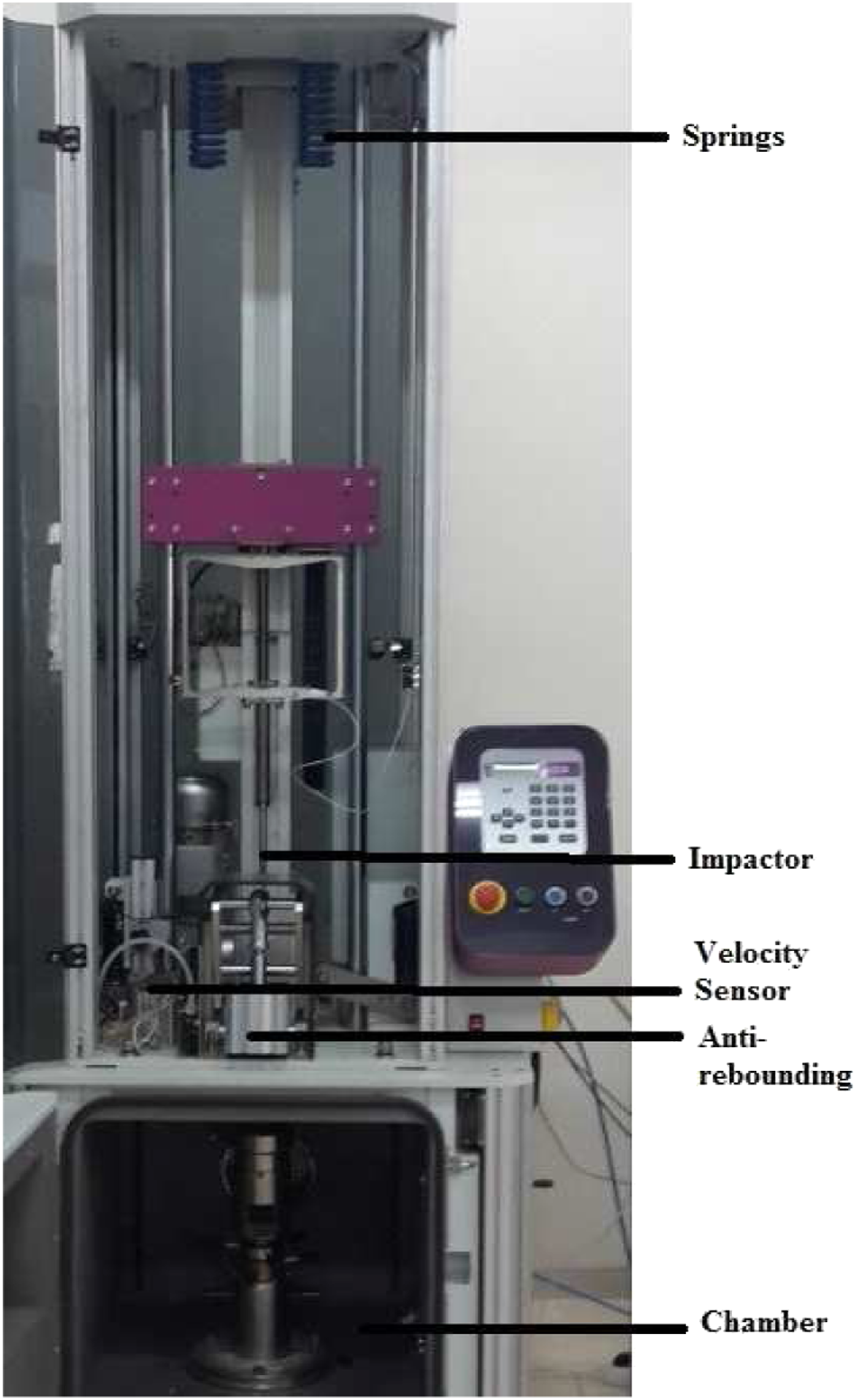
In this study, the sandwich composite structures were placed in the test chamber as seen in Figure 4 and low-velocity impact tests were conducted by Ceast Fractovis Plus impact test machine as shown in Figure 5. The machine has an anti-rebounding system that activates automatically to prevent unwanted impacts. The impactor has a connection with a piezoelectric force transducer. The software uses Newton’s second law and kinematics relations and converts obtained data by Data Acquisition System (DAS 16,000). In this study, a 4.92 kg mass impactor with a hemispherical steel nose of 12.7 mm (0.5 in.) diameter was used. The sandwich composites were clamped between the pneumatic circular support and fixed circular support during a test. The inner diameter of fixed support was 76.2 mm. Impact test chamber. Drop weight impact testing machine.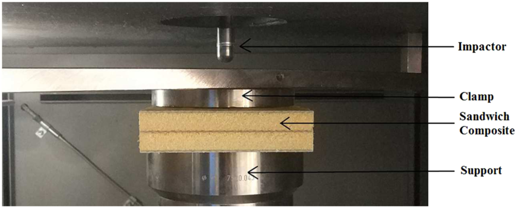
The low-velocity impact performance of sandwich composite structures was investigated at four different impact energies. Pretesting was carried out for this study. The penetration and perforation energies were selected according to this pretesting. Impact velocities, 4.942, 5.143, 5.340, and 5.525 (m/s) correspond to energies of 60, 65, 70, and 75 (J), respectively. Impact test was performed on sandwich composites with codes of “S, 2S, and 2Sec” for impact energy values of 60J, 65J, and 70J with codes of “2Scs and 2Sfs” for 65J, 70J, and 75J impact energy values. Absorbed energy, maximum displacement and contact time are obtained for these impact energies. For comparison of the sandwich composites the results for 65J and 70J are considered. The contact force data between the sandwich composite and the impactor were obtained as a function of time and displacements.
Results and discussion
Contact force-time and contact force-displacement behaviors can be seen in Figures 6 and 7. There are two peak force values for contact force curves of “S” sandwich composite. If the impactor has enough energy to perforate the sandwich composite, the contact force starts to increase rapidly when the impactor touches the top facesheet and reaches to first peak force. As fiber breakage occurs and fiber breakage increases, the contact force decreases, the contact force value is very low while the impactor moves through the core material, which is very weak compared to facesheet material. After the impactor passes the core material and reaches the lower facesheet, the contact force starts to increase again rapidly up to second peak force. Fiber breakage occurs in the bottom facesheet and the contact force decreases due to the increase of fiber breakage, and the sandwich composite is perforated. Contact force – time curves. Contact force – displacement curves.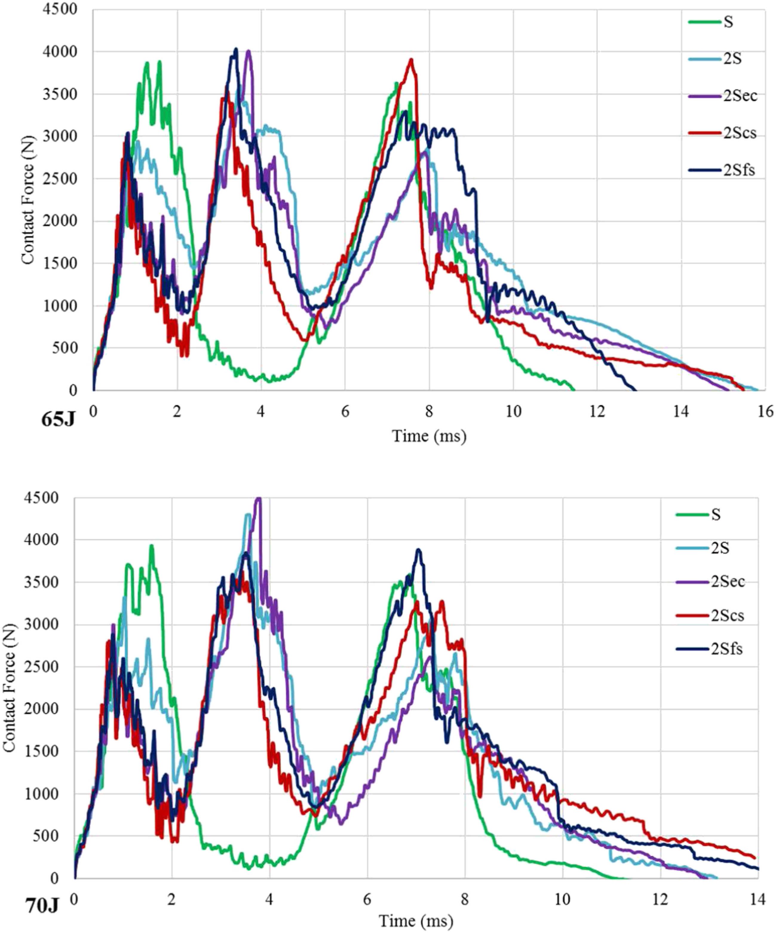
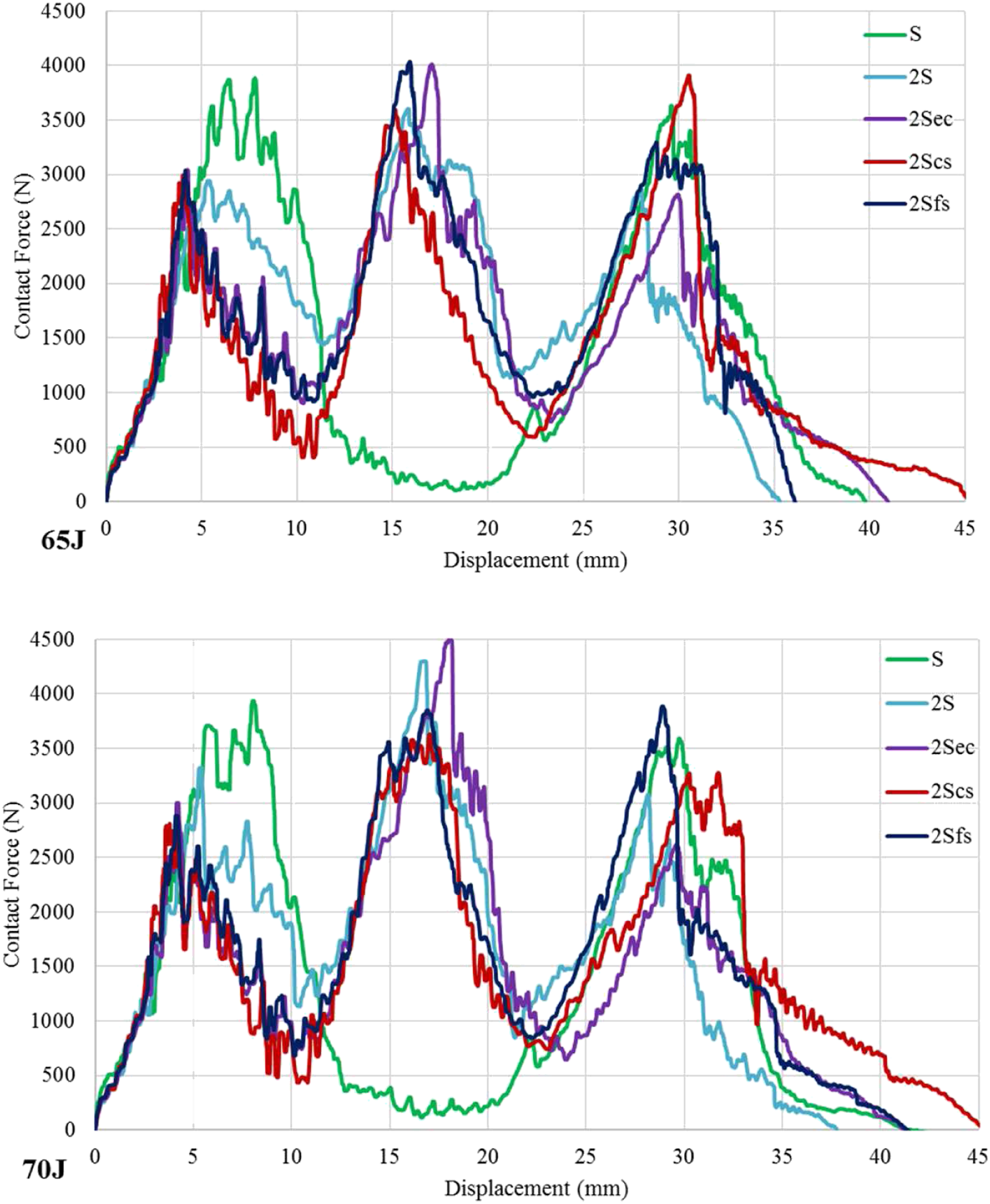
“2S, 2Sec, 2Scs, 2Sfs” sandwich composites have similar low-velocity impact behaviors in terms of contact force curves (Figures 6 and 7). There are three peak force values in these curves. This can be attributed to the number of sheets; top facesheet, middle sheet and bottom facesheet. When the impactor has enough energy to perforate the two-core sandwich composite, during the low-velocity impact, the contact force starts to increase rapidly up to first peak force since the impactor starts to contact the top facesheet. Then fiber breakage occurs and fiber breakage increases causing the decrease in the contact force. The contact force value decreases somewhat while moving through the upper core material, which is very weak compared to facesheet material, then the force value starts to increase again because there is contact to the middle sheet. This phenomenon repeat itself for the middle sheet and bottom facesheet.
Absorbed energy, maximum displacement and contact time values of the sandwich composites.
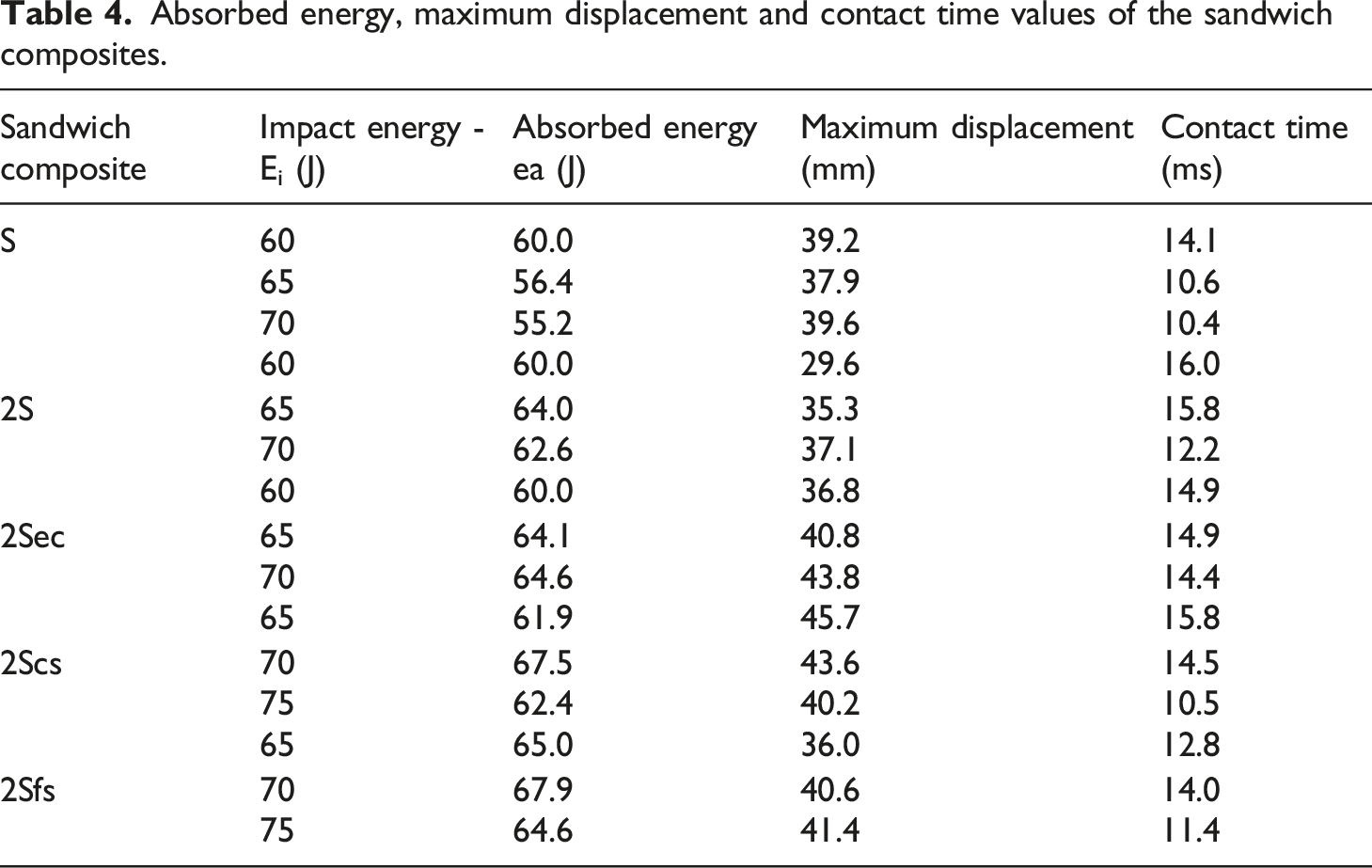
“S” sandwich composite at 60J penetration energy value, the contact time is the maximum because the motion of the impactor stopped at the lower facesheet which could not be fully perforated. When there is perforation, the contact time decreases as the impactor perforates the sandwich composite. This situation causes an approximately 3.5 ms difference in between the penetration and perforation contact times. For “2S” sandwich composite, 60J is the rebounding energy and 65J is about penetration energy however 70J is perforation energy value; the contact time difference is approximately 3.7 ms caused by the difference between penetration and perforation behaviors. For “2Sec” sandwich composite, displacement values are increasing with increasing impactor velocity and the contact time values are nearly the same at all energies. On the contrary of “2Sec” sandwich composite, for “2Scs” sandwich composite impact test results give decreasing displacement values with increasing impactor velocity. “2Sfs” sandwich composite had 65J penetration energy value and thus at this energy value there is difference with “2Scs” sandwich composite however for other energy levels the parameters are nearly the same.
There are two facesheet layers in the one-core sandwich composite “S”, thus two peak force values have been formed (Figures 6 and 7). Three facesheet layers in a two-core sandwich composite “2S, 2Sec, 2Scs, 2Sfs” had three peak force values. The peak force values were given in Figure 8 for 70 J impact energy. As seen in the given Figure 8, for “S” sandwich composite, top facesheet peak force values are higher than the top facesheet peak force of two-core sandwich composites because one-core sandwich composite facesheet is thicker. For middle sheet “2S” and “2Sec” sandwich composites had higher peak contact force values than “2Sec” and “2Sfs”. The decrease in this force caused by stitching yarn. The stitching yarn distorted glass fibers in the facesheet layers and as seen in the results, the peak force values of stitched sandwich composites lower than non-stitched two-core sandwich composites. At the same time the peak force values of middle sheets in “2S” and “2Sec” are relatively higher than all other peak force values. This can be explained by the fact that both sides of the middle sheet had core materials and thus there is the resin-rich bonding area which increases middle sheet thickness. In addition, the core material under middle sheet supports middle sheet during the impact event. The peak force of bottom facesheet for “S” sandwich composite is as expected. The stitched two-core sandwich composites “2Scs”, “2Sfs” show that the stitching process increases contact force values of bottom facesheets. The obtained results had a harmony except for peak force of bottom facesheet in “2Sec”. From contact force-displacement diagrams, the absorbed energy and the maximum displacement of “2Sec” sandwich higher than that of “2S” sandwich composite. This means that there exist more failures in the top and middle layers, cores, and epoxy column of “2Sec” sandwich composite. As a result of these, the bending stiffness of “2Sec” decreases more and bottom facesheet peak force in “2Sec” is smaller than that in 2S. Peak contact forces for 70J impact energy.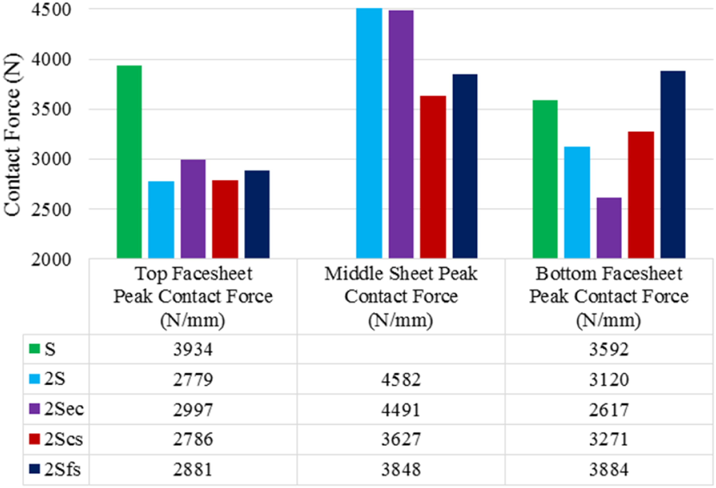
Dynamic rigidities or bending stiffnesses for 70 J impact energy are given in Figure 9. The slope of force-displacement curves in linear region was used to compute dynamic rigidity. Top facesheet layer of “S” sandwich composite had lower dynamic rigidity than two-core sandwich composites except for “2S”. The epoxy columns and stitched columns within these sandwich composites support top facesheet and increase dynamic rigidity even though these sandwich composites had less facesheet thicknesses. Dynamic rigidities of middle sheet in two-core sandwich composite with stitched columns are higher than those of non-stitched ones. The sandwich composites with stitches are observed to have nearly the same values. “2S” sandwich composite has the lowest bottom facesheet dynamic rigidity. As seen in Figure 9, epoxy columns, core stitched and facesheet stitched gradually increase dynamic rigidity at bottom facesheet. “S” sandwich composite shows maximum dynamic rigidity at bottom facesheet. Dynamic rigidities for 70J impact energy.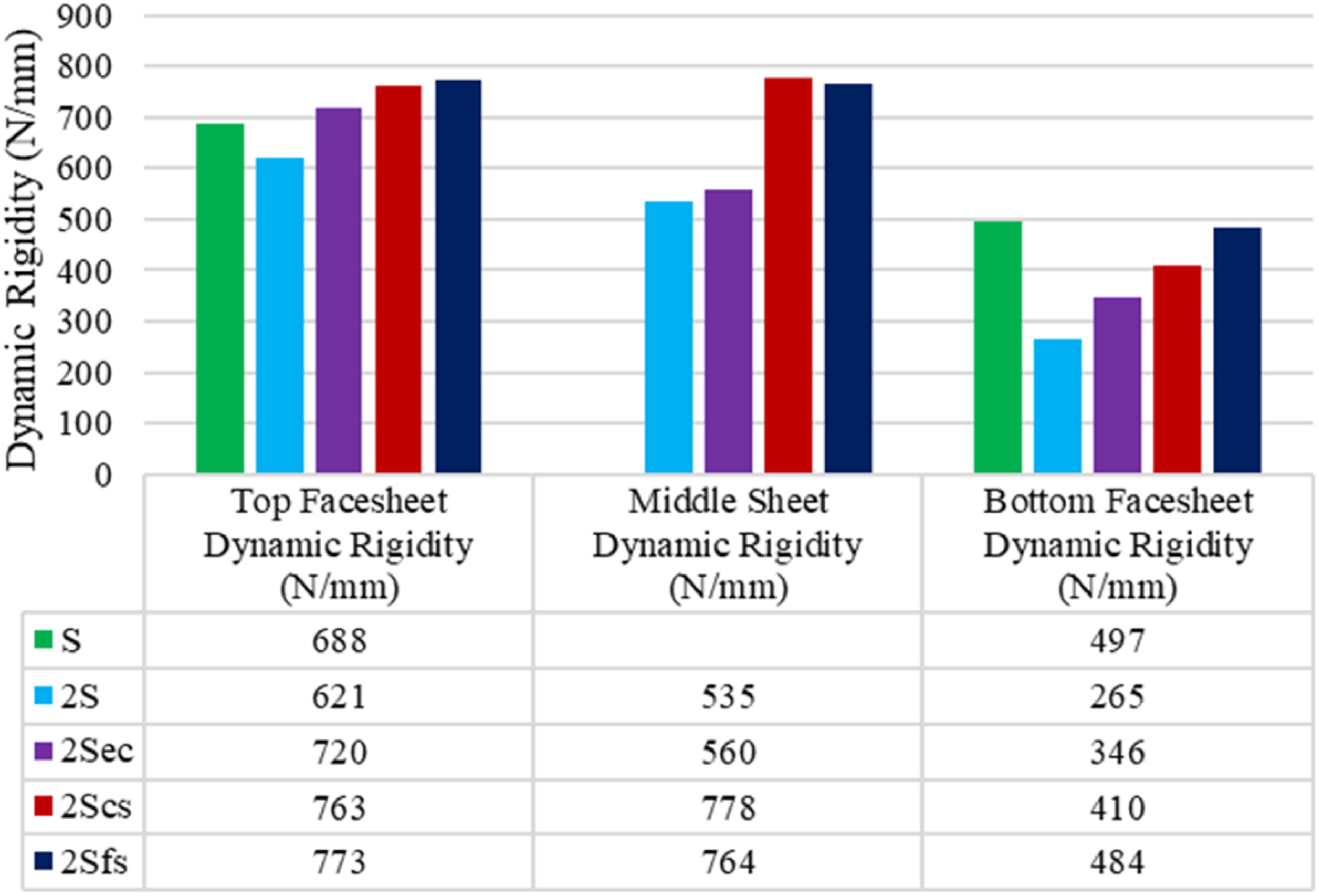
After the low-velocity impact test, as example, the damage images with same zoom ratio on the top and bottom surfaces of sandwich composites for 70J impact energy are given in Figure 10. For “S” sandwich composite, the fibers with the orientation angle of 45° at the top facesheet is evident in the region close to the perforated area of the impactor, while the debonding of the core material and the fiber can be seen due to the intense white coloration. While the fibers with the orientation angle of 45° can also be seen on the bottom surface, there is some whitening due to the impact damage on the boundary area between the bottom facesheet of the sandwich composite and the annular bottom support. Top and bottom views of specimens after impact for 70J energy.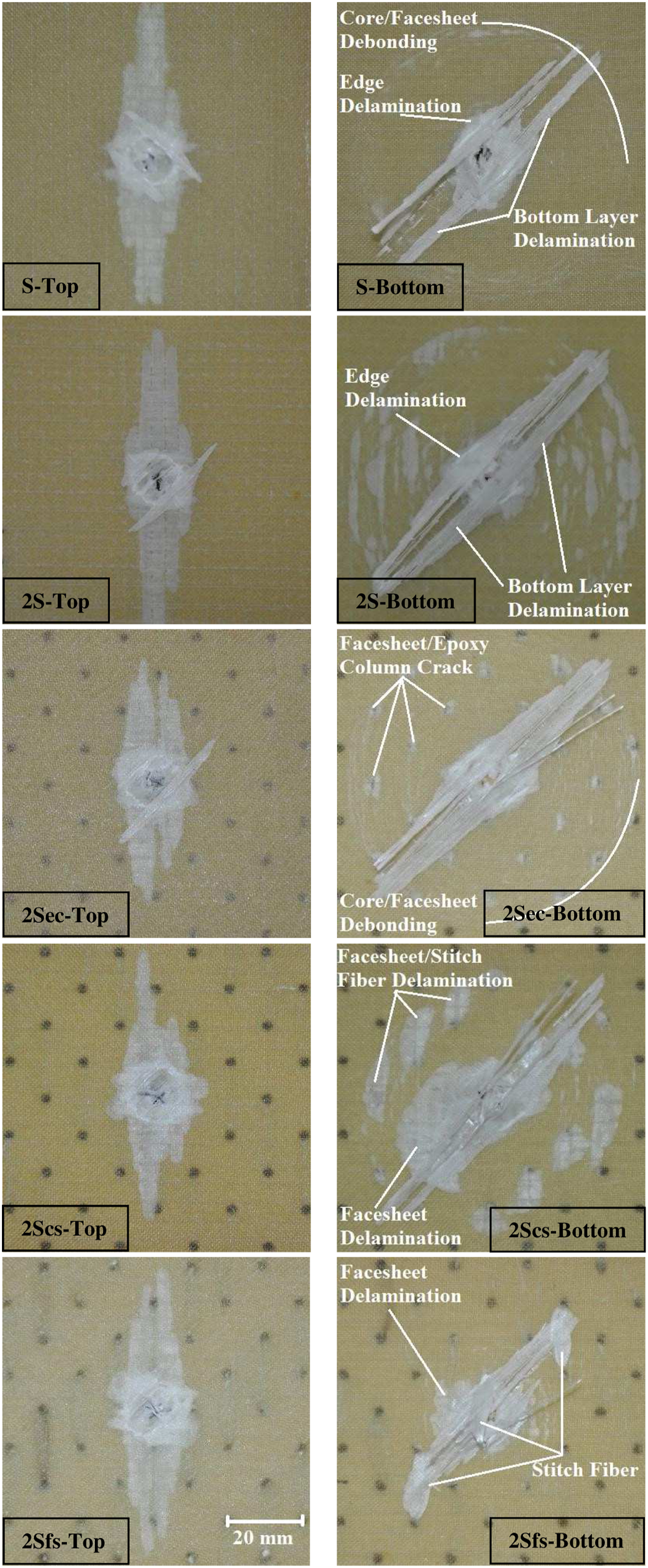
For “2S” sandwich composite, as “S” sandwich composite, the fibers with the orientation angle of 45° on the top and bottom surfaces are evident due to the damage, while the debonding of the fibers from the core material can be seen. Since the top and bottom facesheets in “2S” sandwich composite are thinner than “S” sandwich composite, whitening in the top facesheet due to impact and more whitening due to the annular lower support in the bottom facesheet are observed. For “2Sec” sandwich composite, the debonding between the core material and the facesheet are observed in a smaller area compared to “S” and “2S” sandwich composites. While the 45° angle of fiber orientation is seen on the bottom surface of “2Sec”, impact damage on the bottom surface is observed to be nearly the same with “S” and “2S” sandwich composites. These white-colored debonding zones are visible in the areas where the columns meet the facesheet material.
On the top surface of “2Scs” sandwich composite, the debonding between the core material and the facesheet is seen in a smaller area than “2Sec” sandwich composite. This is due to the fact that the core material stitched has reduced the core/facesheet debonding area. While the 45° angle of fiber orientation is seen on the bottom surface, impact damage on the bottom surface can also be seen locally for “2Scs”. These white-colored regions show the debondings that occurs where the core stitching yarn comes into contact with the facesheet material. In “2Sfs” sandwich composite, the 45° angle of fiber orientation is visible on its bottom surface, it appears that debonding is prevented by the facesheet stitching yarn. It has been determined that the core/facesheet debonding area between the bottom facesheet and the core material was decreased. It can be seen that the area of core/facesheet debonding between the bottom facesheet and the core material is much smaller for “2Sfs” than the rest of the sandwich composites.
It is seen that core/facesheet debonding area of “S, 2S, 2Sec” sandwich composites is nearly same with the inner area of bottom support. Edge delaminations are observed around the perforated zone at the bottom facesheet, and bottom layer delamination had no further delamination at the bottom facesheet of the sandwich composite. 31 For “2Sec” sandwich composite, the breakage of the columns from the bottom facesheet is seen in Figure 10. While the debonding between the stitched and the facesheets can be seen in the “2Scs” sandwich composite, the debonding proceeds parallel to the facesheet material as in other sandwich composites. Since the stitch connects the core and facesheet material in the sandwich composite “2Sfs”, the core/facesheet debonding area is expected to be smaller 25 and it can be seen from the Figure 10 that there is less damage area than the other sandwich composites. The stitches significantly decrease the delamination in the bottom layer.
To understand the damage areas more clearly, the cross-section views of the low-velocity impact regions are given in Figure 11 with same zoom ratio by cutting the sandwich composites. These figures show the damage inside the sandwich composites caused by the impactor. While it is seen that the bottom facesheet and core material are debonded in the “2S” sandwich composite, core shear failure occurs at upper core. The bottom facesheet and core are debonded inside core material because the core material is very weak compared to epoxy. Failure occurs between epoxy columns and facesheets due to the impact in the “2Sec” sandwich composite. Epoxy columns shifted the core shear failure from upper core to lower core material. Stitching yarn can be seen in the “2Scs” sandwich composite; it can be noted that debonding occurs more locally and closer to the stitch yarn. On the other hand, in “2Sfs” sandwich composites, the yarn, which stitched the facesheet material, is seen and while the stitching yarn breaks, no debonding between the facesheet and core material is observed for all facesheets. Cross-section views of specimens after impact for 70J energy.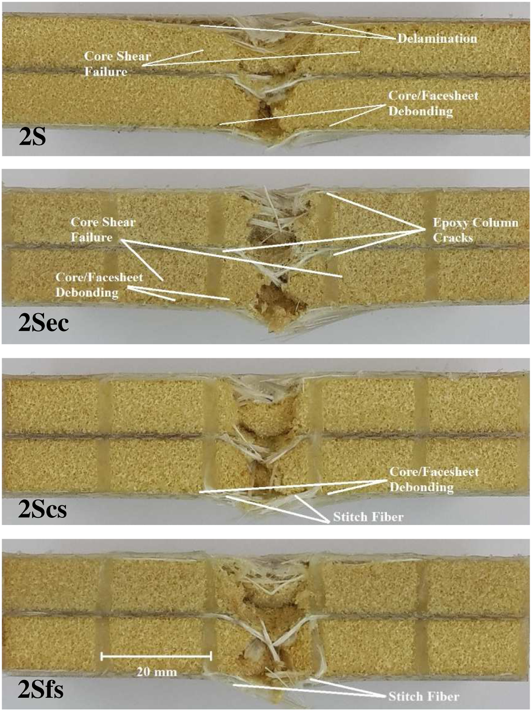
In the “2Scs” sandwich composite, the debonding between facesheet materials, core material, and stitching yarn are seen. The portion of the stitching yarn remaining on the surface of the core material and the bonding surface of the facesheet material with epoxy significantly increased the performance of the sandwich composite. Besides, thanks to this stitch, the damaged surface area in the core material increased, helping to absorb more energy. The damaged surface of the “2Sfs” sandwich composite is similar to the “2Sec” damage in terms of core material damage. Since the facesheet material is stitched in “2Sfs”, the stitching yarn must be completely broken for the damage occurring, which plays an important role in preventing of the core/facesheet debonding crack in the core material. Therefore, the least core/facesheet debonding area occurred in “2Sfs” sandwich composite.
To examine more clearly the damaged area; the sandwich composites were kept in a dark-colored penetrant liquid. During the retention time in the dark-colored liquid, the liquid has penetrated into the damaged area. Due to the transparent glass fiber, the leakage of dark liquid into damaged areas can be seen in the debonding areas of the sectioned sandwich composites (Figure 12). Debonding areas in the sandwich composites were calculated using the ImageJ image processing program. While damage area which is 2420 mm2 is almost equal to the inner area of the lower support in the “2Sec” sandwich composite, the damage area is reduced to 1870 mm2 and 760 mm2 in “2Scs” and “2Sfs” sandwich composites, respectively. In other words, debonding area decreases 23% by core stitches and 69% by facesheet stitches in “2Scs” and “2Sfs” sandwich composites, respectively, comparing the “2Sec” sandwich composites. Tensile stresses cause out of plane core/facesheet debonding. The top view damage images obtained from the tensile test in the previous study
29
confirm these results on the impact damage areas given above. Debonding areas of specimens after impact for 70J energy.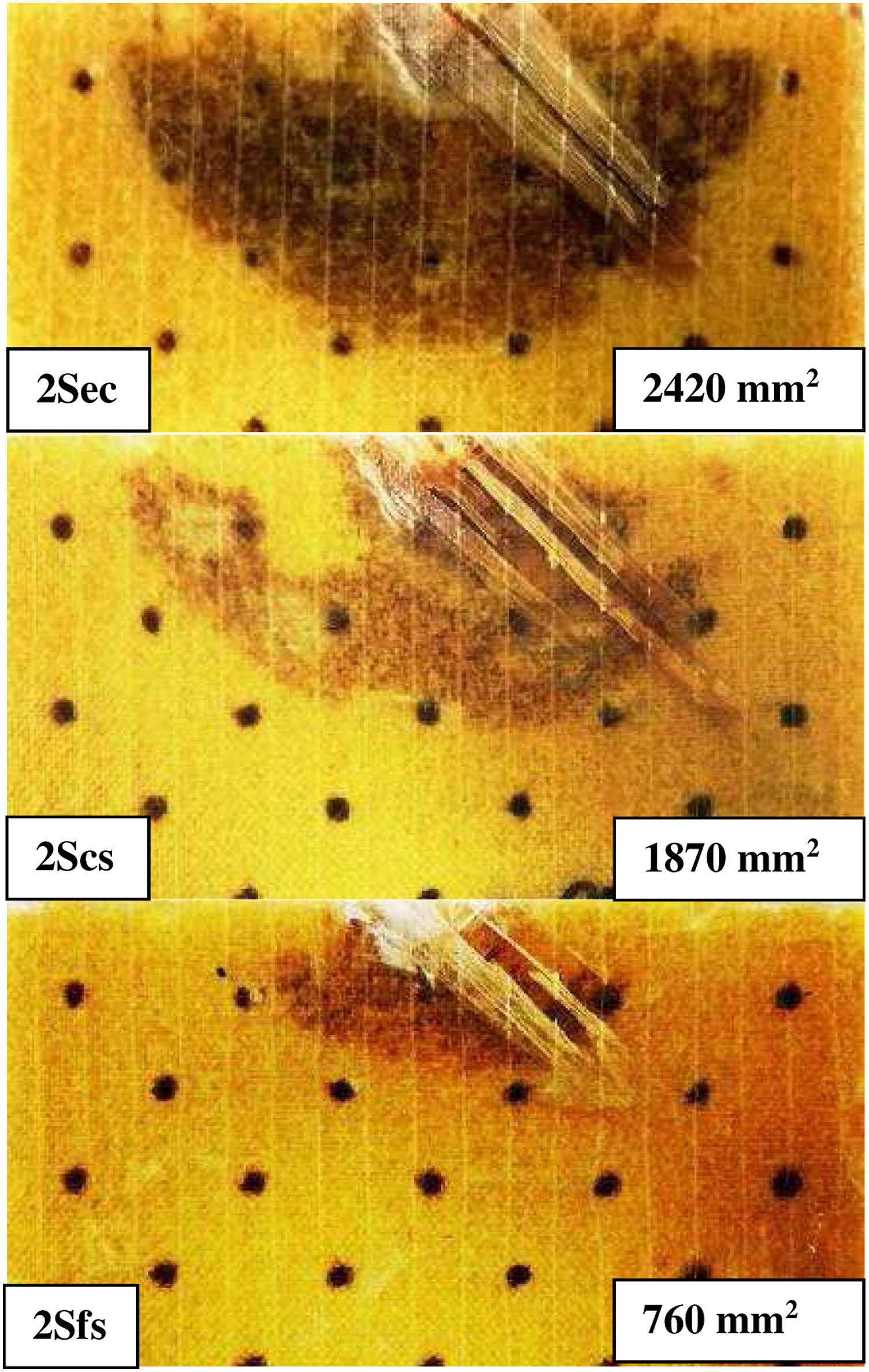
Conclusion
In this study, various structural configurations have been carried out experimentally to increase the low-velocity impact performance of the foam core sandwich composites. The contact force-time curves, contact force-displacement curves, absorbed energy, displacement, contact time values, and core/facesheet debonding areas of the configured sandwich composites are observed. The effect of each configuration on sandwich composite performances has been studied. The core/facesheet debonding areas are examined. From the results obtained, the following conclusions can be drawn; The epoxy columns increase the energy absorbed in low-velocity impact. For the two-core sandwich composite with cores stitched, the absorbed energy value increases compared to the two-core sandwich composite with epoxy columns. In two-core sandwich composites with facesheet stitched, the facesheet stitching process caused a slight increase in the absorbed energy value compared to the two-core core-stitched sandwich composite. The difference in the absorbed energy of these sandwich composites may be that the core stitching yarn can be damaged less than the facesheet stitching yarn during stitching process.
The behaviors of sandwich composite structures that contain a plain core, two-core, and two-core with epoxy column show similar behavior in terms of core/facesheet debonding. The highest decrease in core/facesheet debonding is obtained in facesheet stitched sandwich composite. Because stitching yarns must be broken before the initiation of core/facesheet debonding. Although not as much facesheet stitching, core stitching also reduces core/facesheet debonding significantly. This situation is caused by stitch yarn contact with the facesheet. Stitching yarn and facesheet material have better adhesion strength than core materials. Stitching yarns and core materials on the failure path makes the core/facesheet debonding initiation harder.
The methods that increase the impact performance of the sandwich composite have been examined. Each enhancement of the core material brings additional processing. According to the needs of the designed structure, for instance, wind turbine blade, yacht hull where there is need more load carrying capacity, the sandwich composite structure with two-core, epoxy column, core stitched, or facesheet stitched can be preferred accordingly. It has been determined from the obtained data that core stitching can be performed as an alternative to facesheet stitching, which was previously examined in many studies. In the following study, the numerical analysis will be completed, and numerical and experimental results will be compared.
To prevent the stitching yarn from damage due to friction during stitching, the stitching yarn can be used as resin-impregnated beforehand or with protective coatings which can be a future study. Since the resin-impregnated fiber will occupy less volume, it may also allow the use of thicker yarn. Studies can be carried out using different types of the fiber.
Footnotes
Declaration of conflicting interests
The author(s) declared no potential conflicts of interest with respect to the research, authorship, and/or publication of this article.
Funding
The author(s) received no financial support for the research, authorship, and/or publication of this article.