
Abstract
A significant feature about the application of adhesive joints in various structures is their ability to join dissimilar materials, thus effectively maintaining the structural integrity regardless varying loads. In this paper, the bending collapse behavior of adhesively bonded hat section sandwich beam (HSSB) structures with using of aluminum and steel were investigated. Four configurations of HSSB with different materials for the upper hat beam and lower plate were subjected to quasi-static three-point bending tests as part of the experimental investigation. In comparing the specific absorbed energy (SEA) of the beams, a sample of a hat section sandwich beam with a steel upper hat and an aluminum lower plate had a higher SEA value despite the load-displacement and bending collapse behavior similar to the hat section sandwich beam with a steel upper hat and a steel lower plate. subsequently, a finite element model was developed for bending collapse analysis and a theoretical prediction based on the Kecman model was presented to investigate the hinge moment on HSSB. Based on this, the findings of the numerical study and the predicted theoretical model were in good agreement with the experimental results. The effect of adhesive thickness, the identical mass, and the thickness of the upper hat and lower plate were examined for the purpose of performing an in-depth analysis of the influencing parameters in HSSB structures.
Keywords
Introduction
In recent decades, thin walled structures have become more prevalent in numerous industries, such as the automotive, aerospace, and marine sectors. Consequently, the research and development of body vehicle structures, which have the potential to reduce the quantity of kinetic energy generated by the impact, has become an acceptable option. Among the various energy absorption mechanisms, thin-walled structures as one of the most productive methods have been employed in the automotive industry due to their lightweight, high energy absorption capacity, and high drop distance.1–5 The primary contributors to impact energy absorption during vehicle collisions are the front and side structures.6,7 The upper and lower rails, along with the crash box in the front structures, absorb a significant portion of the impact energy. A number of researchers have examined the energy absorption of tubes undergoing axial compression by analyzing a variety of factors, including geometry, substance of the material, and loading rates.8–13 Conversely, research has also been undertaken to examine the mechanisms through which energy is absorbed through bending collapse in side collisions. The main study has been focused on analyzing the geometries of multiple materials joined using distinct processes.14–20 Moreover, it has been demonstrated that geometry function plays important role in energy-absorbing parameters. In recent decades, hat section sandwich beam structures have been commonly utilized in automotive body structures. The development of new lightweight multi-material automotive body structures has become an important focus in current automotive manufacturing. The application of multi-material hat section sandwich beam structures represents a viable strategy for achieving weight reduction within the automotive industry.
The joining techniques that have been employed present a challenge for the automotive industry when utilizing these novel materials. For example, the use of spot welding for joining the hybrid steel-aluminum sections can be difficult due to differences in thermal conductivities and melting points between the two materials. As a result, numerous research undertakings have been performed to apply varied joining techniques, including co-molding, adhesive bonding, spot welding, fastening, and riveting, in energy absorber structures.21–27 Salamati et al 28 provide a comprehensive overview of various joining by forming techniques that can be utilized to join dissimilar materials. In the other hand, adhesive bonding has attracted the most interest among the methods mentioned above due to its cost-effectiveness, overall reduction in stress concentration, and structure light-weighting. According to recent research about adhesive bonding in structures, 29 by developing three distinct types of adhesive joints-epoxy from the prepreg, an additional layer of epoxy, and 3M adhesive tape, Dhaliwal and Newaz 30 examined the effect of interface bonding and failure mechanism on adhesively bonded hat section aluminum and woven carbon fiber plies. Golivari et al. 31 showed that the integrity of the structure during the test and causes the edges can be maintained by using the adhesive bonding as a part of the hybrid bolted-adhesive joints in the multi-material aluminum and steel double hat section thin walled structures. Three variations of steel hat section components were examined in a study by sanketh et al. 32 These variations were included the use of conventional discrete spot-welds to join flanges, continuous adhesive bonding exclusively, and a hybrid configuration that utilized both adhesive bonding and scarce spot-welds. The study offered valuable insights into the mechanical behaviors of double-hat sections made of adhesively-bonded steel when subjected to impact loading. Therefore, the main focus of this article is to investigate the use of adhesive bonding for the multi-material structure of the hat section beam under the quasi-static three-point bending load.
Due to the transverse loading of hat section sandwich beams, it is essential to understand the bending collapse behavior of each component. Several theories have been developed with regard to the bending collapse of beams. A set of theoretical prediction formulas for the bending moments with a fixed hinge line was also devised by Kecman 33 who initially introduced a model that predicted the bending collapse of a rectangular tube. Research subsequently focused on the development of theories and the development of novel equations for bending collapse, as demonstrated by Wierzbicki et al. 34 and Abramowicz and Jones. 35 By employing Kecman’s theoretical model, Kim and Reid 14 enhanced the theoretical prediction formula for the bending moment of thin-walled structures with rectangular sections. In the continuation of the studies, theoretical models for bending collapse behavior and energy absorption mechanism were studied for circular hollow tubes 36 and different multi cell structures.37,38 On the other hand, in studies of different geometric sections, Duan et al. 39 employed Kecman’s theoretical model to theoretically predict top-hat thin walled structures under transverse loading. They were able to predict a new theoretical model by separating the bending moments of the plastic hinges of the upper hat beam and the lower plate and integrating their final bending energy. However, the description of complex plastic behavior of materials and the delamination between the top hat beam and lower plate require the use of a Finite Element Analysis (FEA) model for predicting the behavior of damage and failure criteria, in addition to the development of analytical equations. Damage evolution outcomes have been determined through the utilization of continuum damage mechanics-based methodologies, including rigidity degradation, for plate bending 40 and composite pin-joints. 41 Abaqus, LS-DYNA, and other numerical simulation programs have implemented energy-based damage evolution formulations in recent times. These methodologies establish the damage evolution law by utilizing the fracture energy that is lost during the damage procedure. In order to model delamination utilizing cohesive elements, 42 the cohesive zone model (CZM) serves as the generalized model of the energy-based damage law. The Anderson-proposed cohesive zone model for delamination has been developed 43 for more complex applications. Damage initially results from the level of stress or strain that exceeds a specific condition, assuming a process zone in front of the fracture tip; the process zone is subsequently regulated by the traction-separation laws.
It seems that a complete and detailed study includes experimental investigation and finite element modeling of dissimilar aluminum and steel beams with adhesive bonding under quasi-static load, and then extending it to the prediction of theoretical models based on the bending moment of plastic hinges of dissimilar hat section sandwich beam structures has not been enumerated in published literature. Also, there is a need to improve the prediction of the behavior of theoretical modeling of adhesive joints under transverse load and to investigate the role of adhesive joints in energy absorption capabilities and bending collapse in beam heat section structures. In the present paper, similar and dissimilar Aluminum/Steel HSSB jointed by structural adhesive bonding, have been fabricated and experimentally tested under a quasi-static three-point bending test. In addition, four configurations with the ability to change the materials of top hat beam and lower plate were considered. As previously mentioned, modeling approaches including explicit nonlinear finite element code LS-DYNA and theoretical model prediction based on Kecman’s theory were used to compare with experimental results and also to study the effect of identical mass and variable thickness of the top hat, lower plate and adhesive components.
Experimental methodology
Materials
In this research, specimens of hat sections have been fabricated using a different material with adhesively bonded joints. With regard to materials, aluminum 5083-H111 and steel 304L sheets with a thickness of 1 mm were utilized. These materials were bent and cut into rectangular plates and hat-shaped samples. Important characteristics of steel 304L and aluminum 5083-H111 are their high impact resistance and high resistance to corrosion when exposed to environmental conditions, respectively, for usage in the automotive and aerospace industries. For the bonding between the hat beams and lower plates, Araldite2015 with a weight ratio of 100/90 (resin/hardener), a ductile epoxy adhesive with high shear and bending strength, was used as the interface adhesive. Around 0.8 mm was the approximate thickness of the adhesive for the bonding.
Fabrication of specimens
To manufacture the hat section sandwich beam specimens, the hat beam and lower plates were bonded using the adhesive joint technique. As shown in Figure 1, the bottom edges of the hat beams and the side areas of the lower plates were sanded for a few minutes with 150-grit sandpaper to guarantee perfect adhesion. After the process of sanding, the adherend surfaces were treated with acetone for an estimated duration of 10 minutes in order to remove any fine particles and remaining grease.
44
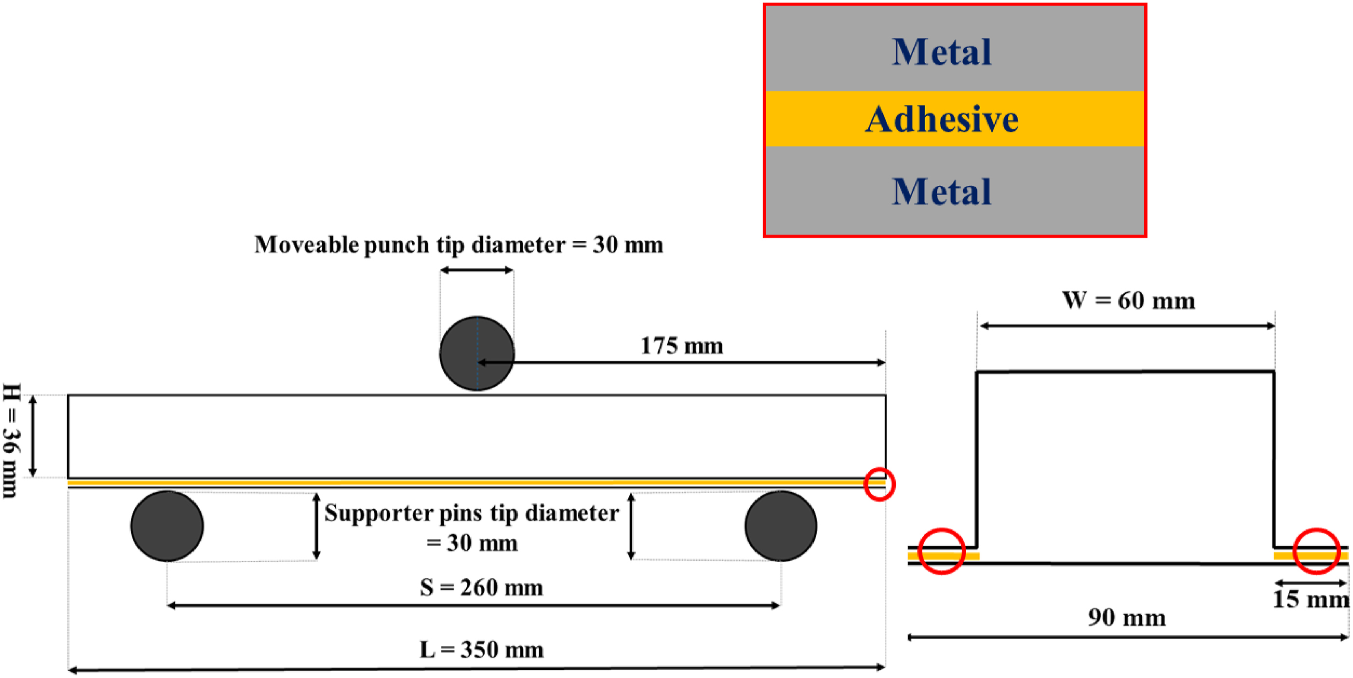
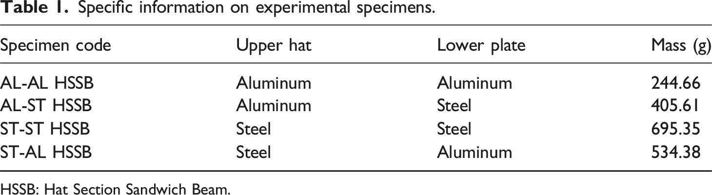
Subsequently, for 168 hours at room temperature, the hat beam samples and lower plates were bound with specialized holding fixtures in order to maintain the pressure level of 0.1 bar throughout the curing process of the adhesive. The obtained dimensions of the specimens, including a lower plate and a HSSB, as well as the necessary test measurements, are illustrated in Figure 2. Moreover, a summary of the description of each specimen is presented in Table 1. Adhesive bonding process of hat section beam specimens (HSSB). Description of beam specimen dimensions and schematic of three bending point test conditions. Specific information on experimental specimens. HSSB: Hat Section Sandwich Beam.
Test method
An effective method for observing the bending collapse caused by local buckling, which occurs frequently in the center under transverse loading conditions, is the three-point bending test. As depicted in Figure 3, the HSSB specimens performed quasi-static bending tests using a universal testing machine (STM150, SANTAM Co.) equipped with a loading capacity of 150 kN. The specimens were situated in a configuration involving a puncher and two support pins. The radius of the puncher and supports were 15 mm and the test span was consistently maintained at 260 mm, which corresponds to an approximate 3.61 ratio between the test span and the beam’s height.
45
The puncher was adjusted to bend upward and move at a speed of 4 mm/min. Load displacement data started automatically upon system initiation and continued until the evaluator terminated the system. An optical camera was utilized to record the three-point bending test so that the plastic deformation of the specimens could be examined. Experimental setup for three-point bending test.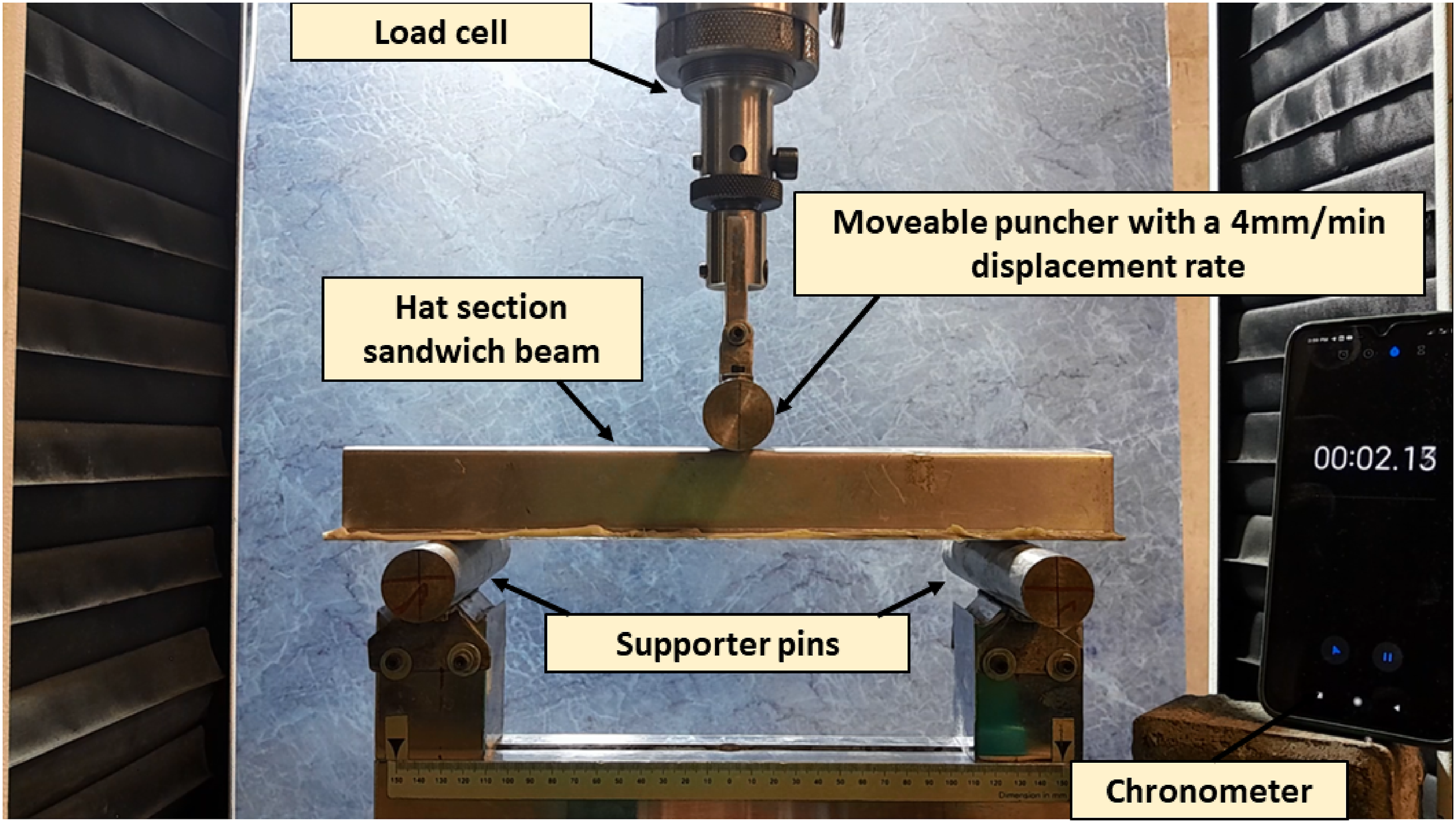
Theoretical prediction
The evaluation of the energy absorption properties of HSSB can be facilitated by a method that makes use of theoretical prediction modeling to investigate the energy absorption and bending collapse of thin-walled structures in the absence of material specifications and geometric data. The current investigation is based on the Kecman theory model, 33 which calculates the energy absorbed by each plastic hinge line generated throughout the bending collapse. The current analysis for hat section sandwich beams is founded upon Kecman’s initial collapse theory, which has been modified to consider medium thin-walled shapes and potential material changes in the hat beam and lower plate. Additionally, the authors have proposed critical curvature analysis for maximum load for the collapse stage. 46 In addition, this study investigates the energy absorption efficiency of the adhesive utilized to join the hat section beam and the lower plate.
According to Kecman’s theory, the absorbed energy for each plastic hinge line generated during bending collapse is computed. Afterward, by solving the subsequent numerical derivative as a function of 

Each structure is classified into an upper hat beam, lower plate, and adhesive joint component based on its unique deformation and bending behavior in order to estimate the energy absorption and bending collapse characteristics of HSSB. Figure 4 shows a theoretical prediction model for the collapse of hat section sandwich beams based on Kecman’s theory. The theoretical model utilized to characterize beams before bending deformation is illustrated in Figure 4(a). In the given context, the variables l, w, h, and f denote the full length, width, height, and edge of the hat section beam, respectively. The hinge lines KL, LE, and LL1 correspond to the coordinates x, y, and z, accordingly. The bending collapse model of the top hat beam is illustrated in Figure 4(b). The hinge line BC drops as the bending collapse of the upper hat beam initiates. As the bending collapse progresses in the y-direction toward points A and D, it intersects with lines GH and EF to form the collapse areas. Concurrent with the motion of the hinge line BC, there is an increase in the angle of plastic rotation ( Theoretical prediction model of the hat section sandwich beams: (a) hat section sandwich beam before the bending collapse. (b) bending deformation of top-hat beam. (c) bending deformation of adhesive component. (d) bending deformation of lower plate.
Therefore, equation (6) is used to calculate the total absorbed energy of the hat section sandwich beam structures during the three-point bending collapse:
Numerical method
Finite element modeling
Utilizing the explicit nonlinear finite element code LS-DYNA, the bending behavior of the hat section sandwich beam specimens was predicted with double precision. In order to achieve accurate predictions of deformation behavior, the numerical approach was based on the individual modeling of each component. LS-DYNA was utilized to account for explicit time integration in quasi-static analyses. The numerical method employed discrete element modeling to get accurate bending behavior estimates for HSSB, as shown in Figure 5. Five integration points in the thickness direction are taken into consideration while modeling the hat section beam and lower plate utilizing fully integrated shell elements (ELFORM 16). A mesh analysis was conducted to determine the mesh independence for the energy absorption of each section by reducing the element size from 5 mm to 1.5 mm. Accurate numerical results were obtained upon achieving convergence with an element size of 1.75 mm. As a result, it was discovered that the hat section beam contained 18,800 elements, while the lower plate contained 10,200 elements. *CONTACT_AUTOMATIC_ONEWAY_SURFACE_TO_SURFACE_TIEBREAK was utilized to simulate interlaminar delamination in the bonding between the side areas of the lower plate and the outer edges of the hat section beam. Assigned rigid material properties were assigned to the puncher and supporters, which were modeled as a rigid body with Belytschko-Tsay four-node shell elements (ELFORM 2). All degrees of freedom were constrained for the supports under boundary conditions, whereas the puncher had all degrees constricted with the exception of the z directions. The PRESCRIBED-MOTION-RIGID option was employed to characterize the puncher’s motion, which exhibited a rate of 0.5 mm per second and was a quasi-static movement. With a friction coefficient of 0.3 and the soft constraint formulation, *CONTACT_AUTOMATIC_SURFACE_TO_SURFACE is used in the interaction between the specimen and the puncher as well as the specimen and the supports. The set of hat section beam and bottom plate were also used as a single *SET_PART to ensure that appropriate contact was maintained with all specimen components throughout the specimen’s interaction with rigid bodies.48–50 Finite element model of hat section sandwich beam.
Aluminum and steel material model
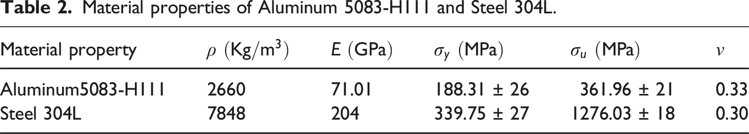
The fundamental material model *MAT_PIECEWISE_LINEAR_PLASTICITY (MAT_024) was utilized to simulate the elastoplastic behavior of Steel 304L and Aluminum 5083-H111. This specific material model possesses the advantageous capability of accommodating an arbitrary stress-strain curve, while also permitting the formulation of any necessary strain rate dependence. The failure criterion in this material model consists of the principal fundamental in-plain strain and the plastic failure strain. The plasticity behavior of the aluminum and steel layers are expressed in the fundamental equations of this material model through the strain rate and yield function, which are defined as follows:
The term 
Strain rate and hardening effects were disregarded in this investigation due to the insensitivity of aluminum and steel to strain rate when subjected to quasi-static loading. As a consequence, the scaling factor β remains constant for aluminum and steel material subjected to quasi-static loading. The stress-strain curve demonstrating the effective plastic strain in the effective stress derived from the three repetitions tensile test of dog bone samples made of steel 304L and aluminum 5083-H111 is shown in Figure 6. The material properties of aluminum 5083-H111 and steel 304L are listed in Table 2 for use in the piecewise linear plasticity material model. Effective stress-effective plastic strain curve of aluminum 5083-H111 and Steel 304L. Material properties of Aluminum 5083-H111 and Steel 304L.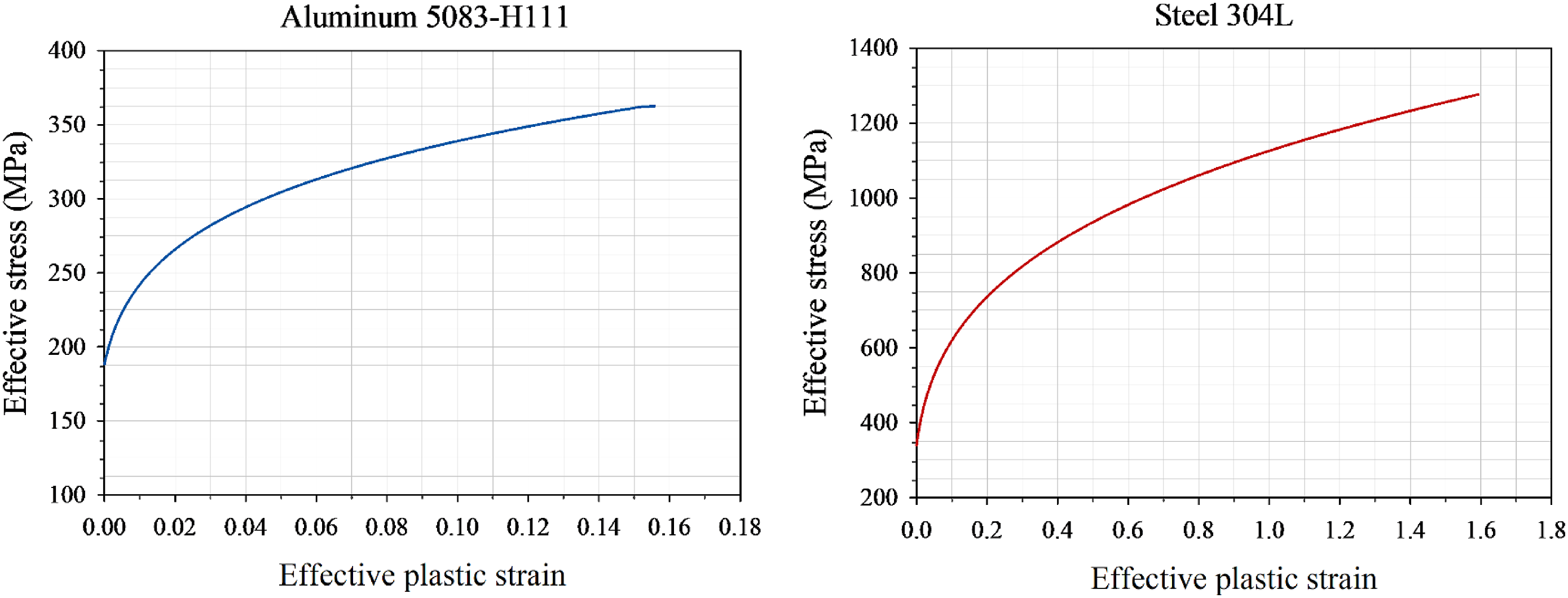
Adhesive debonding model
The adhesive debonding model of the lower plate and edges of the hat section beam shell elements was simulated using Dycoss Discrete Crack Model option 10 LS-DYNA and a tiebreak contact definition (contact one-way surface to surface tiebreak).
51
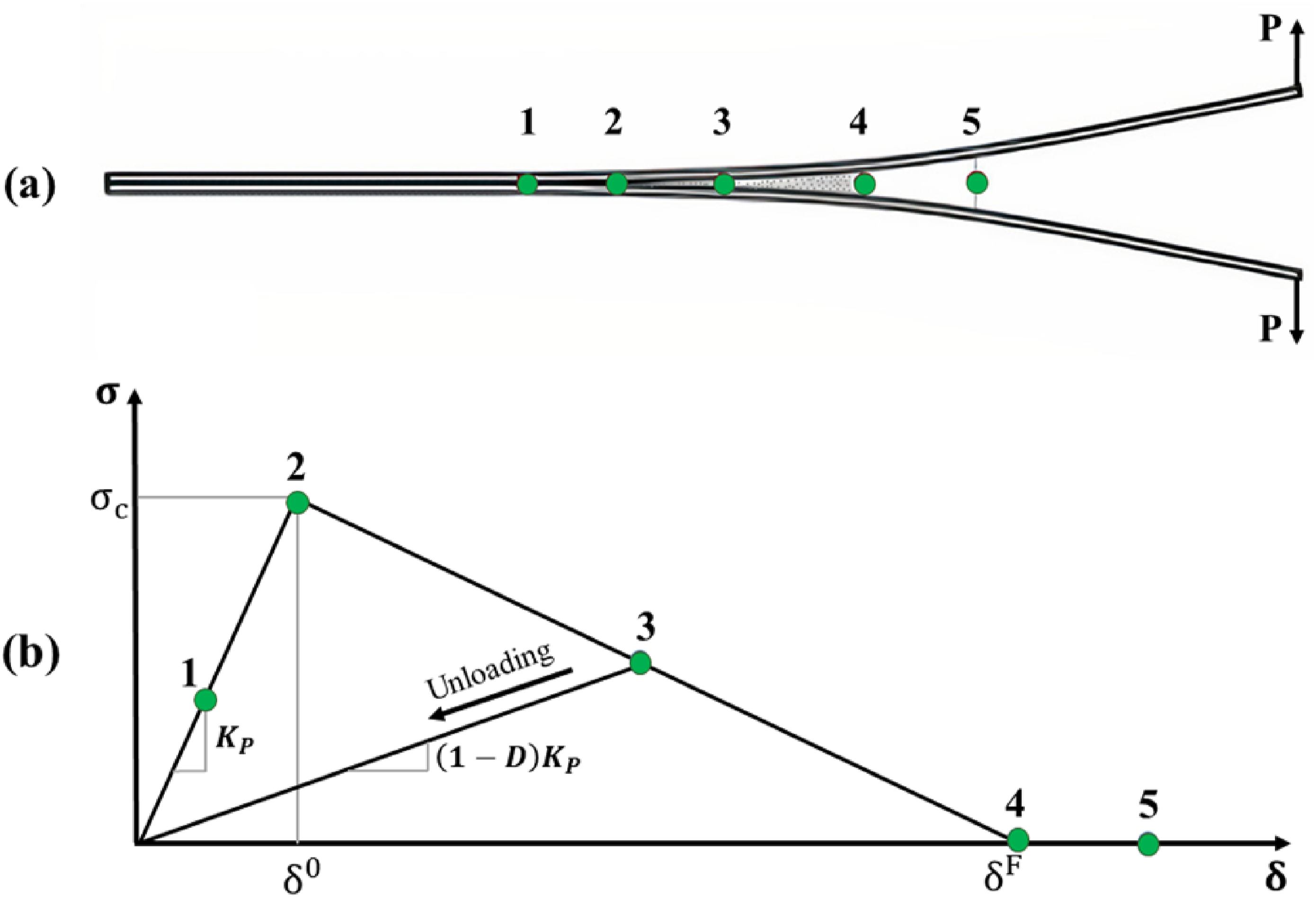
A bilinear fundamental traction-separation law and a quadratic mixed-mode delamination damage criterion are utilized in this tiebreak contact method. The bilinear constitutive model as shown in Figure 7 presents the formation of mode I cracks. The lower figure provides an essential representation of the stress-strain supposition, while the upper plot depicts the critical points involved in the delamination process. Point 1 is located in the elastic region, which corresponds to the material’s behavior. At this point, the unloading will currently adhere to the elastic line due to the undamaged state of the material. Point 2 describes the beginning of the delamination, which causes the material to soften as the loading increases. Upon the loading reached point 3, a certain degree of damage has been inflicted (damage parameter is greater than zero but less than one). However, the damage incurred is not yet sufficient to separate the plies. when full delamination occurs at point 3, it is presumed that the unloading will proceed along the start line from point 3 to 0. In Figure 7(b), the region bounded by points (0-2-3) symbolizes the unusable energy lost due to partial bond damage. Point 4 is where the material is irreparably separated as a consequence of the material incurring severe damage as the burden is increased. At point 4, the value of the damage parameter had reached unity value. Bilinear constitutive model for mode crack I in tension.
52

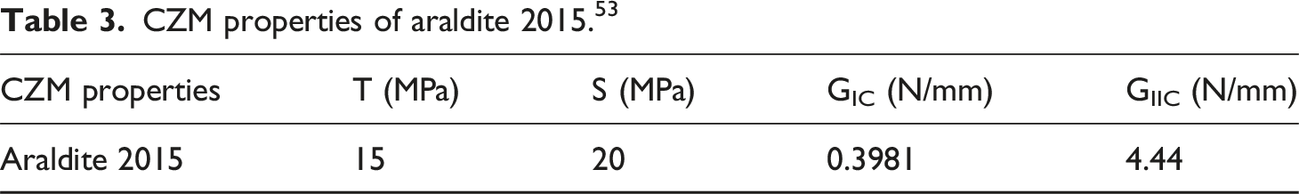
CZM properties of araldite 2015. 53
Result and discussion
Bending behavior of hat section sandwich beams
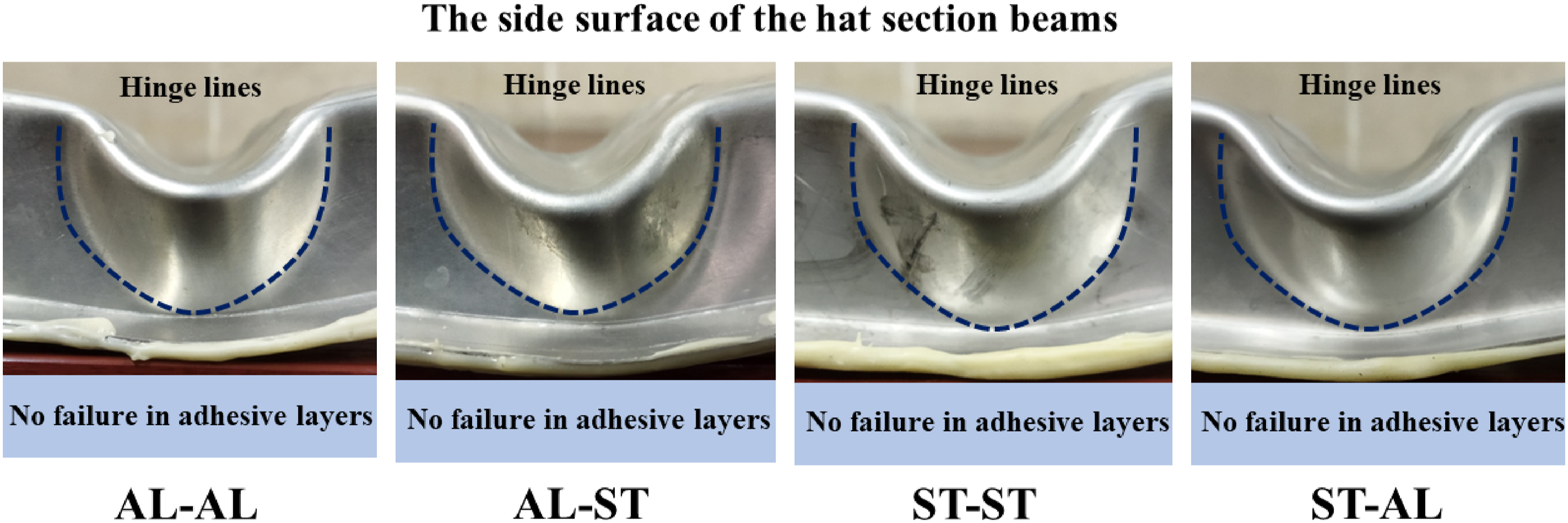
Four configurations of HSSB with different materials for the top hat beam and the bottom plate were investigated with the types of specimens AL-AL HSSB, AL-ST HSSB, ST-ST HSSB and ST-AL HSSB. Figure 8 depicts the bending collapse behavior of the HSSB, which can be delineated into four discrete regions as represented by a load displacement curve. Linear elastic behavior was observed in region I immediately after loading commenced. Subsequently, plastic deformation was detected in region II as a result of the material’s plasticity. Plastic buckling occurs when structures buckle prior to reaching their designated buckling strength; this occurrence is caused by the plastic structure of materials. This phenomenon takes place when the specimen’s front and rear sides stack away from the puncher before the peak load is reached. The reduction in rigidity and strength induced by the plastic behavior of metals results in a concomitant decrease in the buckling resistance of the structure. Following the attainment of the peak load, the bending collapse behavior becomes evident in region III as a result of the plastic hinge formation, and the load subsequently decreases. Region IV involves the submersion of the puncher’s tip into the concave region of the plastic hinge. This process initiates the stacking of the top side of the HSSB along outside of the puncher tip. Whether burden increases or decreases at the conclusion of region IV is contingent on the strength of the bonding between the upper hat beam and the lower plate. In the case of stable bonding, the load undergoes a minor upward slope; conversely, in the event of bond failure, the load gets a downward slope. Furthermore, the plastic hinge line and healthy adhesive bonding of the specimens subsequent to the test are depicted in Figure 9. Load-displacement of HSSB specimens subjected to a three-point bending test. Plastic hinge lines and bonding area of the HSSB specimens.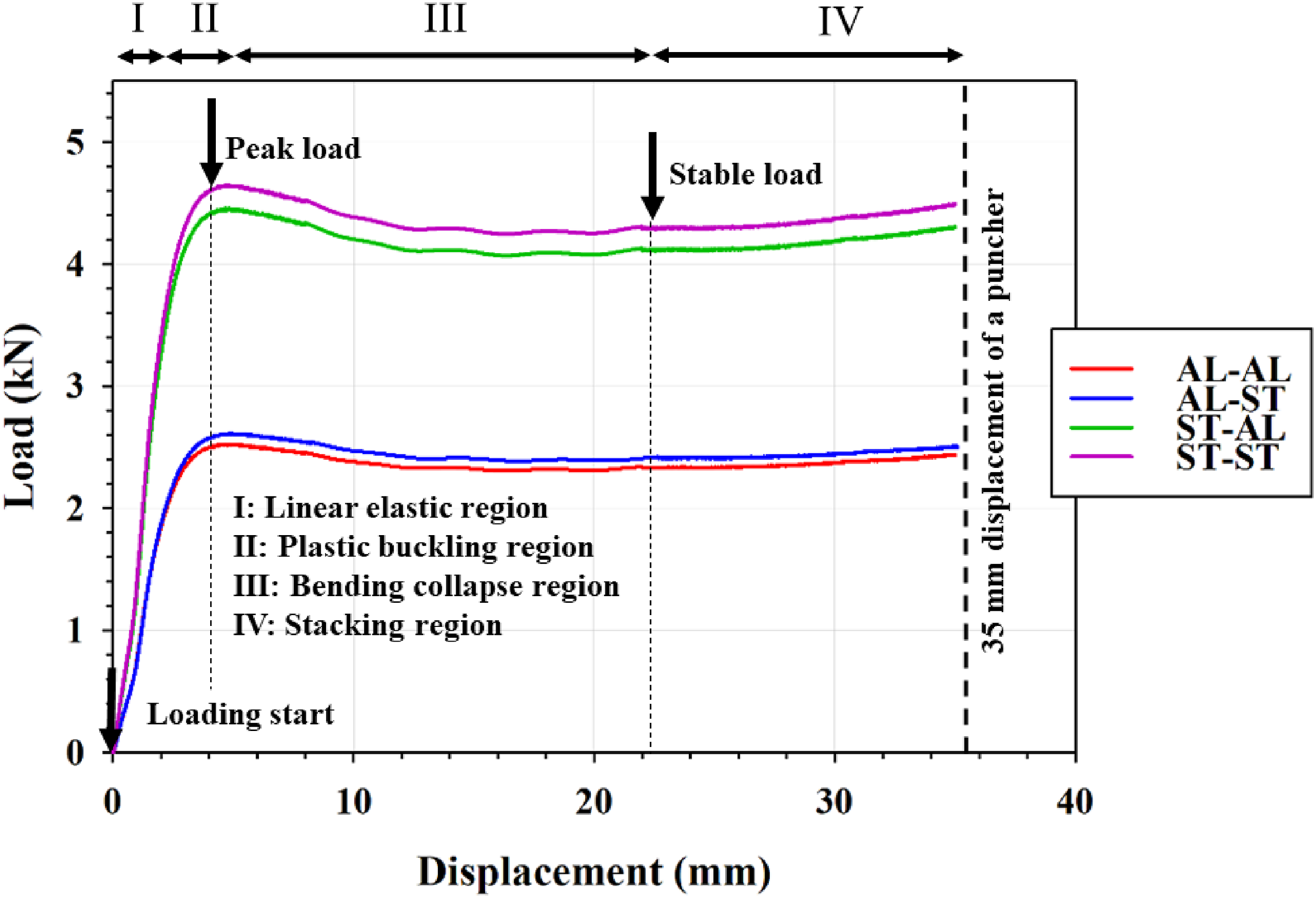
Comparison of energy absorption parameters of HSSB specimens.
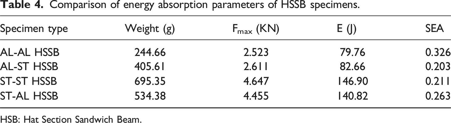
HSB: Hat Section Sandwich Beam.
Validation of the bending behavior of HSSB specimens by the FEM and theoretical model
As shown in Figure 10, the experimental and finite element model (FEM) results obtained from the transformation of the load-displacement plot with the assistance of the support distance were compared to the theoretical moment-angle results to validate their accuracy. The observed errors in comparing the energy absorption response of the HSSB specimens in experimental, numerical and theoretical methods were about less than 10% errors. Therefore, the theoretical and FE model results in this research can simulate the energy absorption characteristics of HSSB specimens and have a good agreement with experimental results. Comparison of moment vs. angle curves of the experimental, numerical and theoretical results for HSSB specimens.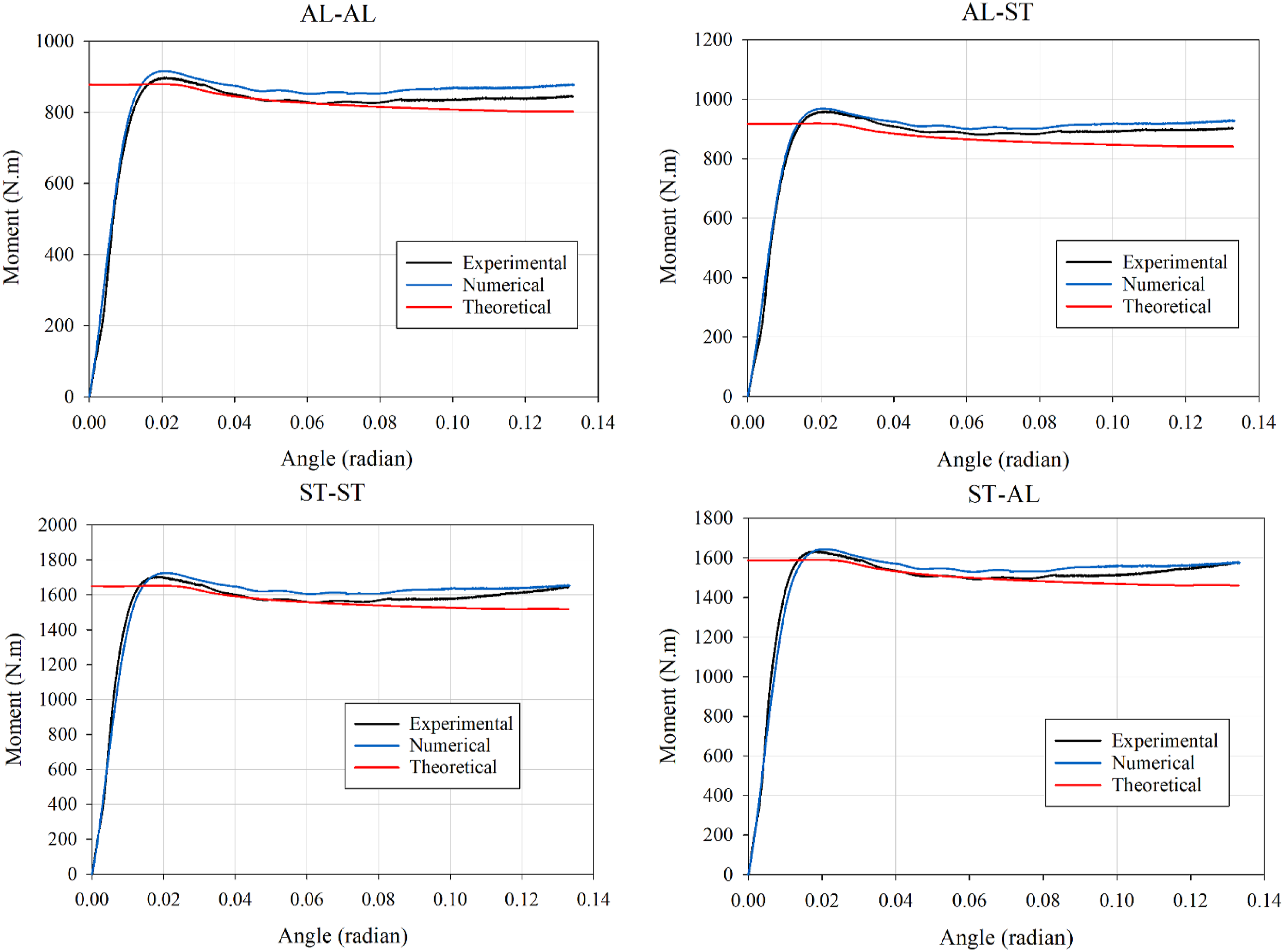
Figure 11(a) shows the bending collapse and the formation of plastic hinges of the HSSB specimens by the finite element model, which is in the form of stress distribution (Von-Mises Stress Contour) in the area under the puncher. The interface delamination damage of the edge areas of the hat section is illustrated in Figure 11(b), along with the measured final displacement of the puncher. Red indicates locations with different damage statuses specified in the finite element method, including critical damage and others; blue indicates healthy and undamaged regions. As indicated by the coloration in Figure 11(b), the damage began in the central region of the bonding area across all specimens. As a result, according to the experimental observations (Figure 9), the adhesive has not been damaged in most of the bonding areas and the deflection has been well transferred from the upper hat beam to the lower plate. (a) Von-Mises Stress Contour at the final displacement for the hat section beams. (b) Upper view of interface damage of the bonding area at the final displacement.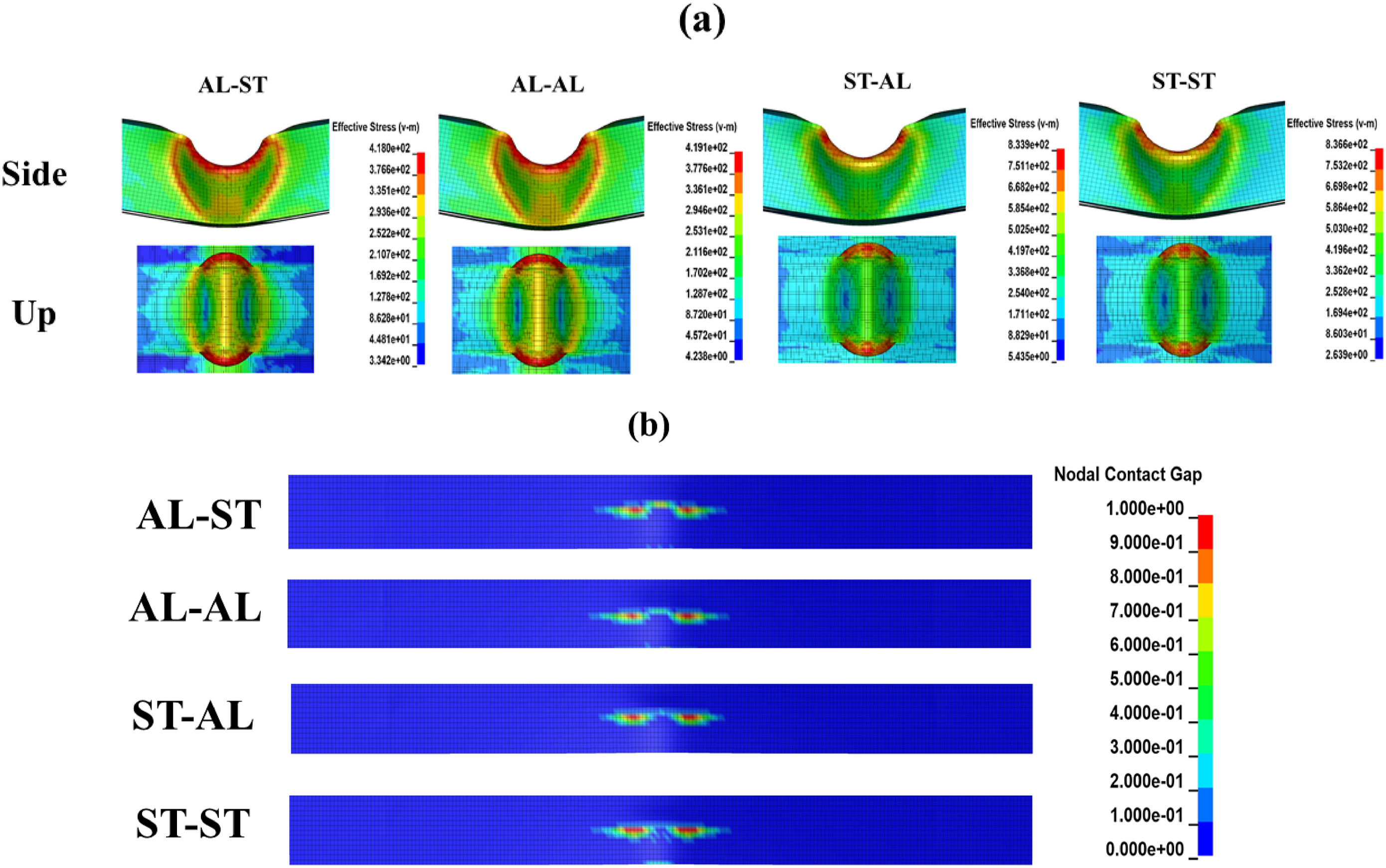
Parametric study
Influence of variable thickness on the energy absorption performance of HSSB specimens
Based on the obtained theoretical modeling, the energy absorption behavior of HSSB with five different thicknesses of 0.4, 0.6, 0.8, 1 and 1.2 mm of steel and aluminum was used for the upper hat beams and lower plates to investigate the effect of variable thickness of HSSB samples on the specific energy absorption response. As shown in Figure 12, in each of the four conditions examined, the trajectory of SEA variations in relation to thickness was a direct ratio. That follows this, the range of SEA changes in the upper hat beams with respect to the thickness is considerably greater than that of the lower plates changes in thickness. Thus, for the same thicknesses of upper hat beams, the maximum SEA value corresponds to a 0.4 mm reduction in lower plate thickness, excluding ST-AL case. On the other hand, the lowest SEA value was recorded in all cases related to the lowest thickness for the upper hat beams (0.4 mm) and the highest thickness for the lower plates (1.2 mm). In addition, it was noted that the AL-AL case exhibited the highest SEA values for the specified thicknesses. The AL-ST, ST-AL, and ST-ST cases were subsequently classified into the SEA values ranking. Specific energy absorption (SAE) of the HSSB specimens with various thickness for the upper hat beam and lower plate.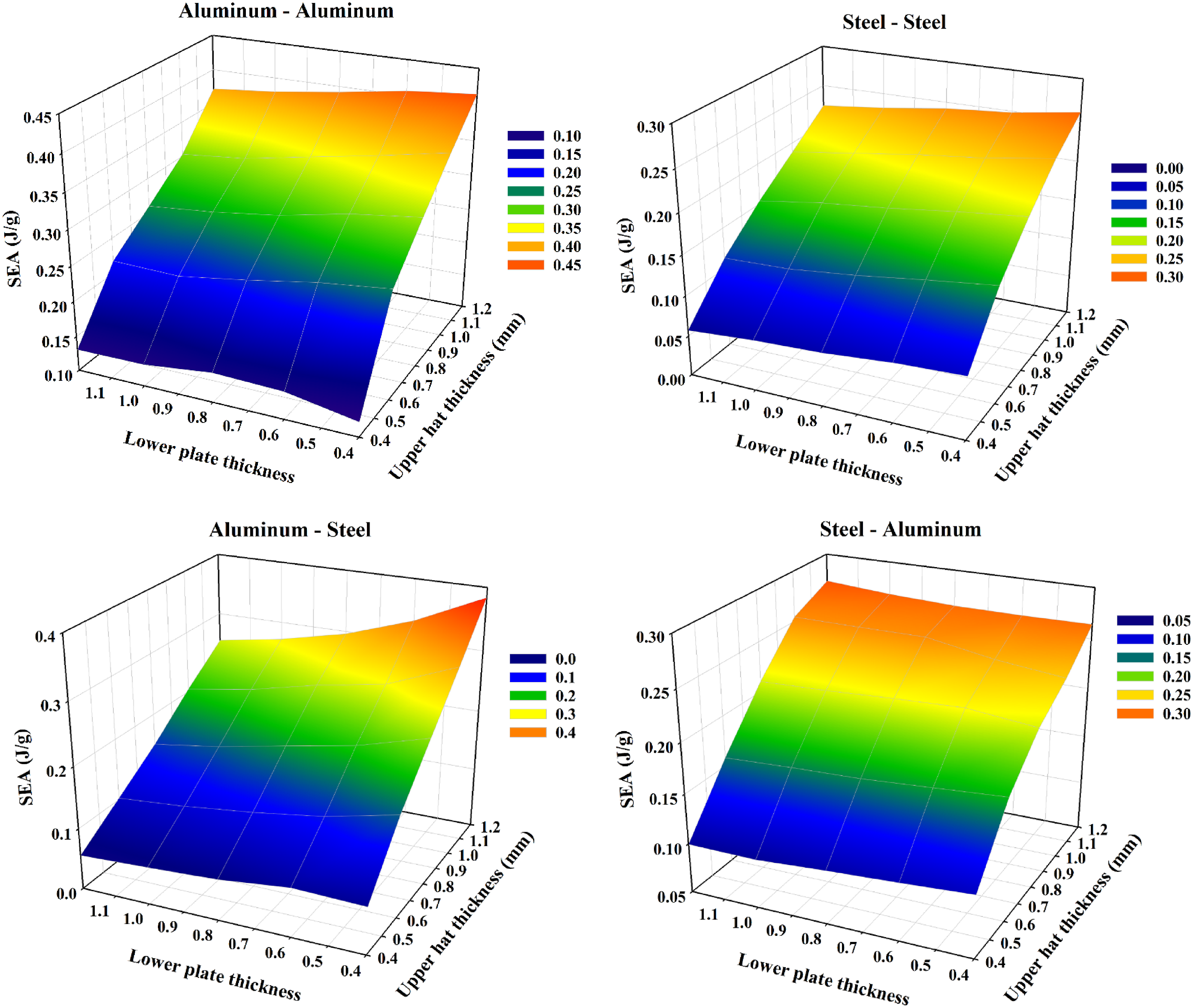
HSSB with identical mass
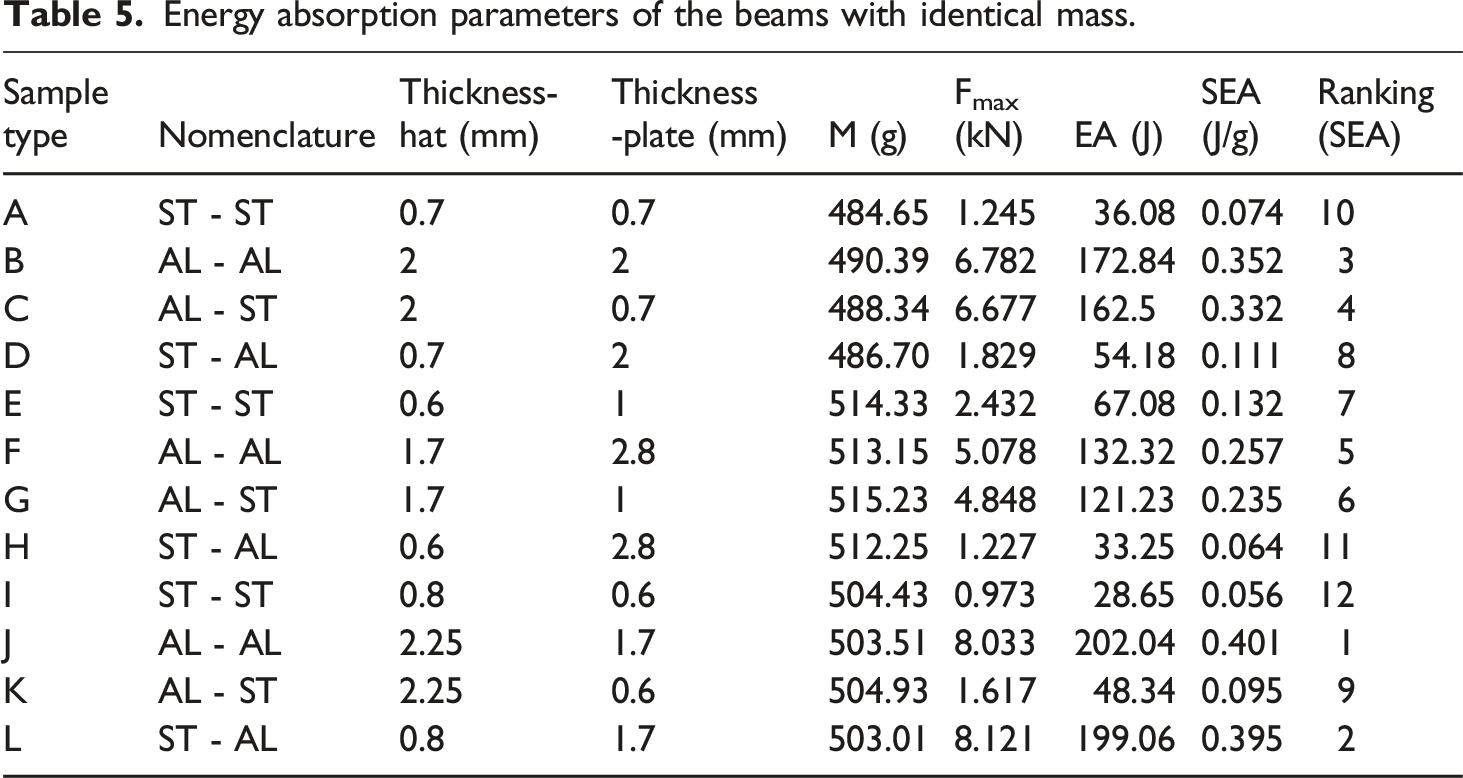
To maintain equality in mass (m = 484 to 505g) among the HSSB, the thickness and material of the upper beam and the lower plate were changed utilized by numerical modeling. The specific energy absorption performance of HSSB specimens with identical masses is illustrated in Figure 13. It was found that specimens with a reduced volume fraction of aluminum in comparison to steel showed a lessened specific energy absorption capacity. This can be attributed to the substantial mass of steel components present in the upper hat beams and lower plates. Comparing the energy absorption performance of full steel beams to that of full aluminum beams indicates that aluminum specimens absorb more energy than steel specimens of identical mass due to their higher thickness. Consequently, it is significant to mention that the SEA value of the steel and aluminum hybrid beams is nearly equivalent to that of the full aluminum specimens for the upper hat with thicknesses of 2.25 and 0.8 for aluminum and steel, and the lower plate with thicknesses of 2 and 0.7 for aluminum and steel. The ranking of specimen categories according to their normalized specific energy absorption capabilities, mass, maximal force, and energy absorption, as well as the thicknesses and materials of the upper hat beams and lower plates, is presented in Table 5. Steel sheet utilization is obviously related to the lowest values of specific energy absorption. Energy absorption has also been minimal in the majority of instances, owing to the thin steel utilized. The comparison of specific energy absorbed (SEA) for different configurations of identical mass for the beams. Energy absorption parameters of the beams with identical mass.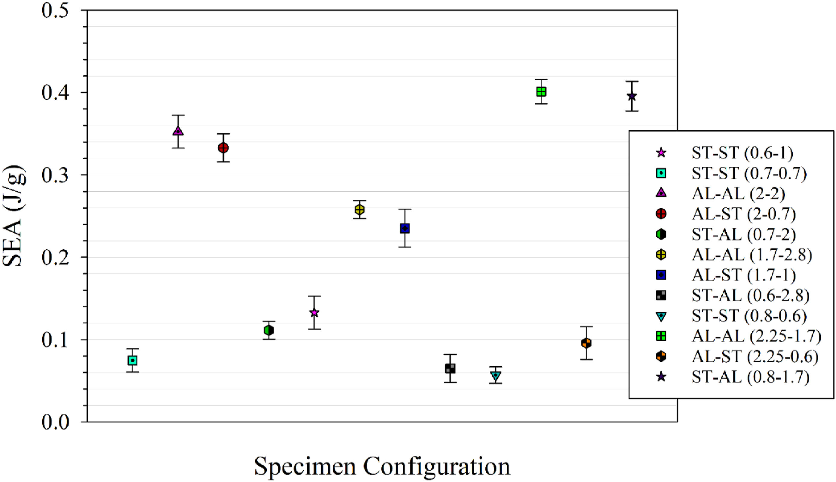
Effect of the adhesive thickness on the energy absorption performance
Based on the theoretical model predicted in this study, the effect of the adhesive thickness on the energy absorption capablities of HSSB specimens with five various thicknesses of 0.8, 1, 1.5, 2 and 3 mm of adhesive layers were investigated. As depicted in Figure 14, the relationship between energy absorption variations and adhesive thickness was direct under each of the four configurations analyzed. Due to this, the aluminum and steel beams, respectively, absorbed a total of 11% and 9% of energy, as indicated by the W8 and W9 hinge lines that were examined in accordance with the hybrid hinge moment in equation (4). Taking into consideration the thickness of 3 mm for adhesive in the W8 and W9 hinge lines, this share of energy absorption in aluminum and steel beams reached 24% and 15%, respectively. However, when the effect of adhesive mass in the HSSB was taken into account for, there was essentially no effective change in the SEA of the samples; in the best case, a 2% increase in SEA was observed. Energy absorption of various thickness for the adhesive in the HSSB.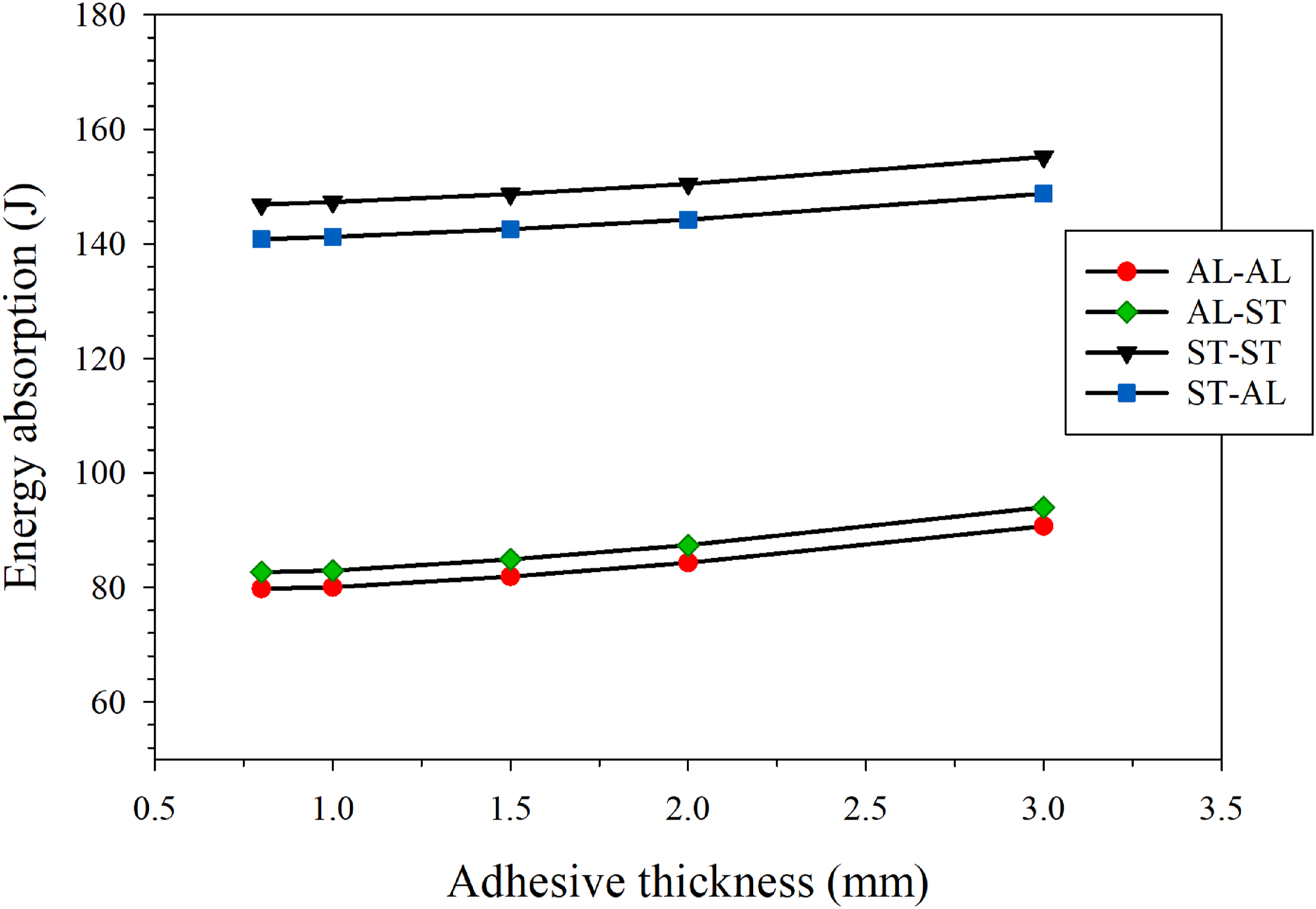
Conclusions
In this paper, experimental, numerical, and theoretical study were used to investigate the bending collapse behavior and energy absorption performance of hat section sandwich beams (HSSB) with various configurations regarding the use of upper hat and lower plate materials (aluminum and steel) and joining by adhesive bonding under a three-point bending load. Considering the Contents presented by this paper, several noteworthy findings can be concluded as follows: • The experimental investigation’s load-displacement data indicated that specimens of HSSB exhibited similar bending collapse behaviors despite having varying energy absorption capacities. Consequently, energy absorption value of the specimens has a direct ratio with the materials of the upper hat beam. In this way, AL-AL, AL-ST and ST-ST, ST-AL HSSB were close in terms of energy absorption. As compared to the specific energy absorption, AL-AL HSSB has a highest in the specimens and SEA value in ST-AL HSSB was recorded with 24% improvement compared to ST-ST HSSB. • The experimental outcomes related to the HSSB specimens exhibited a good agreement with both the predicted theoretical model and the finite element (FE) simulations. Additionally, the analysis of damage in adhesive bonding was conducted to determine the health of the majority of these points in accordance with experimental observations. Following the validation of the FEM and theoretical models, parametric studies were performed on the HSSB specimens. • The effect of variable thickness and identical mass on the energy absorption performance of HSSB specimens were studied. The value of SEA improves as thickness of specimens increases; however, the upper hat beam’s contribution to the ratio of thickness to SEA was significantly greater in all configurations compared to the variations in lower plate thickness. On the other hand, the results of the identical mass indicated that the samples with an increased volume fraction of aluminum compared to steel showed a better specific energy absorption capacity, so that the thicknesses of 2 and 1.7 mm for the top hat and the lower plate of aluminum were the most optimal cases for connecting with other components. • Utilizing a predicted theoretical model based on the integration of the moment of the hinge lines of the edge of the hat beams and adhesive, the impact of adhesive thickness on the energy absorption of structures was investigated. The results indicated that the increase in SEA value is not directly proportional to the mass of the adhesive. Therefore, the utilization of adhesive bonding for load transfer in adherents and maintaining structural integrity does not significantly affect the energy absorption of structures.
Footnotes
Declaration of conflicting interests
The author(s) declared no potential conflicts of interest with respect to the research, authorship, and/or publication of this article.
Funding
The author(s) received no financial support for the research, authorship, and/or publication of this article.
Appendix
EF and GH hinge lines:
BC hinge line:
AB and CJ hinge lines:
BE, BG, CF and CH hinge lines:
EL, GK, FM, HN hinge lines:
AE, AG, CF and CH hinge lines:
AL, AK, JN and JM hinge lines:
KL and MN hinge lines:
KK1, LL1, MM1 and NN1 hinge lines:
M4L4 and N4K4 hinge lines for lower plate:
and the radius at the hinge lines is