
Abstract
Nowadays, composite sandwich tubes are extensively utilized in the civil and aerospace industries due to their superior strength-to-weight mechanical properties. Origami-based core offers a large enhancement of the mechanical properties, yet little study research focuses on the effect of various foldcore configurations on the transverse mechanical properties of sandwich tubes, necessitating the design method for applications. This study introduces an innovative approach by incorporating origami into the composite sandwich core to enhance the transverse energy absorption capacity. The quasi-static transverse mechanical properties of carbon fibre-reinforced polymer (CFRP) sandwich tubes with foldcores are studied under three-point bending-like local compression and transverse structural compression. A systematic geometric design framework and numerical modelling technique are provided. By integrating finite element analysis and experiments, the research investigates the effects of various origami foldcore configurations and geometric parameters on transverse energy absorption capacity. The experiment setup is provided by sandwich tubular specimens with a full-diamond configuration as the foldcore. The cylindrical tubes (foldcore) of the sandwich structures were manufactured using four plies [0°]4 of T700 (T300) woven CFRP with the hot press moulding (vacuum bag using female and male moulds) technique respectively. Then, the parametric study and damage mode analysis of eight different foldcore patterns (axial Miura, circumferential Miura, diamond, Kresling, and their curved-creased counterparts) were studied. The results showed the superior energy absorption performance of the sandwich tube with Miura-pattern foldcore over the origami-pattern counterparts, nested tube, and traditional honeycomb sandwich tube with CFRP or aluminium-made cores. Therefore, the structural parameters optimisation of the Miura pattern tube was carried out by the Response Surface method (RSM) and a design strategy for increasing the energy absorption capacity was found. The findings offer guidance for designing high-specific energy absorption tubular structures for future advanced engineering applications.
Keywords
Introduction
The transverse energy absorption properties of composite tubes play a crucial role in various engineering applications, energy-absorbing tubes are designed to mitigate impact forces during collisions to safeguard passengers, to fabricate lightweight, high-strength components for the enhancement of both the safety and fuel efficiency of aircraft, and to be incorporated into building structures for the improvement of seismic performance, in the fields of automotive, aerospace and civil engineering respectively. Origami structures, characterized by their lightweight, high strength, and tunability, can be designed as promising applications in healthcare, aviation, mechanical, and civil engineering.1–5 Incorporating tubular structures as energy absorption devices has been widely used in the automobile industry.6–14 Origami-inspired tubular structures, compared to conventional tubular structures,15–19 offer predefined deforming patterns through the creases, leading to a lower initial peak force and steady impact load compared with conventional straight tubes, hence their energy absorption capacity could be enhanced due to the structural advancement,20,21 as the majority of the material could be involved in the energy-absorbing process. 22 Composite materials in structures exhibit excellent properties23–25 in areas such as seismic resistance, 26 wave absorption, 27 energy saving,28,29 energy absorbing,30,31 heating insulation 32 and thermal load, 33 making them applicable across various fields including vehicle industry, 34 life sciences 35 and mechanical engineering.36,37 There are different patterns for origami-inspired structures, 38 including the full-diamond,39,40 trapezoid, 41 diamond,42–46 Miura,21,22,38–51 Tachi–Miura, 52 Waterbomb,52,53 and Kresling54–56 patterns. Over the years, origami-inspired tubular structures used as energy absorption devices have been extensively studied. Yasuda et al. 52 found that the stress concentrations at the vertices could cause energy dissipation when studying the Tachi-Miura polyhedron (TMP) tubes. Ma et al. 57 introduced a kite-shaped pattern in the design of thin-walled tubes and studied its crushing behaviours numerically, which shows a superior energy absorption ability than conventional square tubes. Lee et al. 58 incorporated curved creases into the surface of circular tubes as pre-embedded features, enabling precise control over the buckled shape, and resulting in marginal improvements in energy absorption. Ciampaglia et al. 59 investigated the CFRP origami crash box under axial impact and showed that the fracture-triggering effect is better when more inclined planes are at the top. Due to the ability of sandwich structures to further enhance the energy absorption capacity60–64 of both the structure and the material, these origami-inspired tubular structures are often employed as folded cores and assembled into sandwich structures by integrating the foldcore 65 with the inner and outer plates, thereby significantly improving energy absorption capabilities.66,67
However, current studies have primarily focused on the axial mechanical properties of origami-inspired sandwich tubes.16,68,69 Since the working conditions could be complicated in real-time, with the energy shock transmitted from different directions,17,18,70,71 one needs to also consider the energy absorption capacity in the transverse direction, as the cases of under-sea pipes and the fuselage of the aircraft.72–75 Currently, little research focuses on the transverse mechanical property of the origami-inspired sandwich tube structures as energy absorption devices,19,76 and the effects of different origami patterns on the energy-absorbing capacity in the transverse direction remain unknown. Therefore, in this paper, we investigate the transverse mechanical performance of energy-absorbing composite sandwich tubes with origami foldcores under two loading conditions, that is, the three-point bending-like local transverse compression and the structural transverse compression. The designing process of each unit cell of the foldcores is detailed, and the FE analysis is carried out and validated by experiments. The effects of different parameters on the transverse mechanical properties are investigated, then a structural parameter optimization process of the foldcore pattern with the best performance is provided and a design reference is given. Note that two loading conditions here in the study correspond to two scenarios, the transverse concentrated force at the local area and the overall structural compression in the transverse direction, these two scenarios are considered for applications such as the road stake at the highway express to provide the buffering effect for the crashing vehicles, and the undersea pipe which withstands the overall transverse compression during its lifespan. Therefore, the specimen designed for the local compression condition is a “three-point bending”-like test specimen, and hereinafter, this loading condition is phrased as the “three-point bending” test for simplicity and clarity purposes.
The paper is organised as follows. First, the numerical models are discussed in Section Experimental setup and numerical model, with two loading conditions (i.e., the three-point bending and the transverse compression) considered. Since the boundary condition of the three-point bending is a more complicated one in two loading cases, the experiments of this loading condition are carried out to validate the numerical model. Then, the design processes for eight origami-inspired foldcores are demonstrated in Design process of the geometric foldcore configurations Section. Further, the parametric study of the composite sandwich tubes with eight origami-inspired foldcore patterns is conducted under both loading conditions in The results of the parameter study Section, and as one of the main novelties in this paper, the main parameter is identified and the optimization process is carried out and the design strategy is given. Finally, a conclusion is given.
This study primarily investigates the incorporation of origami foldcore into composite tubes to enhance their transverse energy absorption performance. The main novelties of this work are fourfold: 1. The geometric design method and geometric constraint of various origami-based foldcore are proposed systematically; 2. The numerical modelling technique for sandwich structures with foldcore is set up and validated; 3. A parametric study on the effects of various foldcore configurations on the transverse mechanical properties of the sandwich structures is studied and main parameters are identified; 4. A design strategy of sandwich structures with foldcore on the transverse mechanical properties is provided. Therefore, this work systematically investigates and provides a reference for designing composite sandwich tubes with origami cores, filling the research gap in the transverse energy absorption performance of tubular origami sandwich structures.
Experimental setup and numerical model
Material and experimental setup
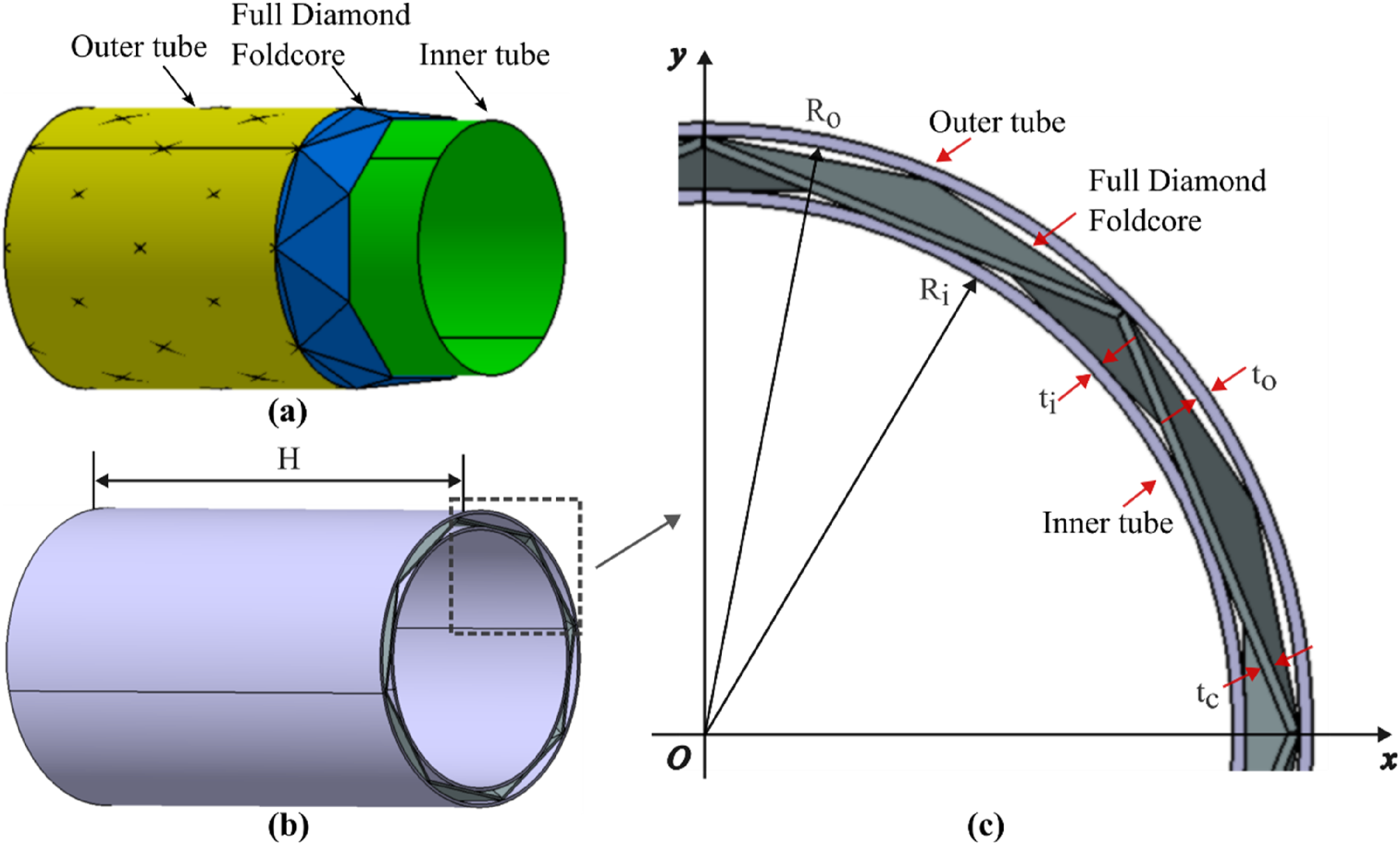
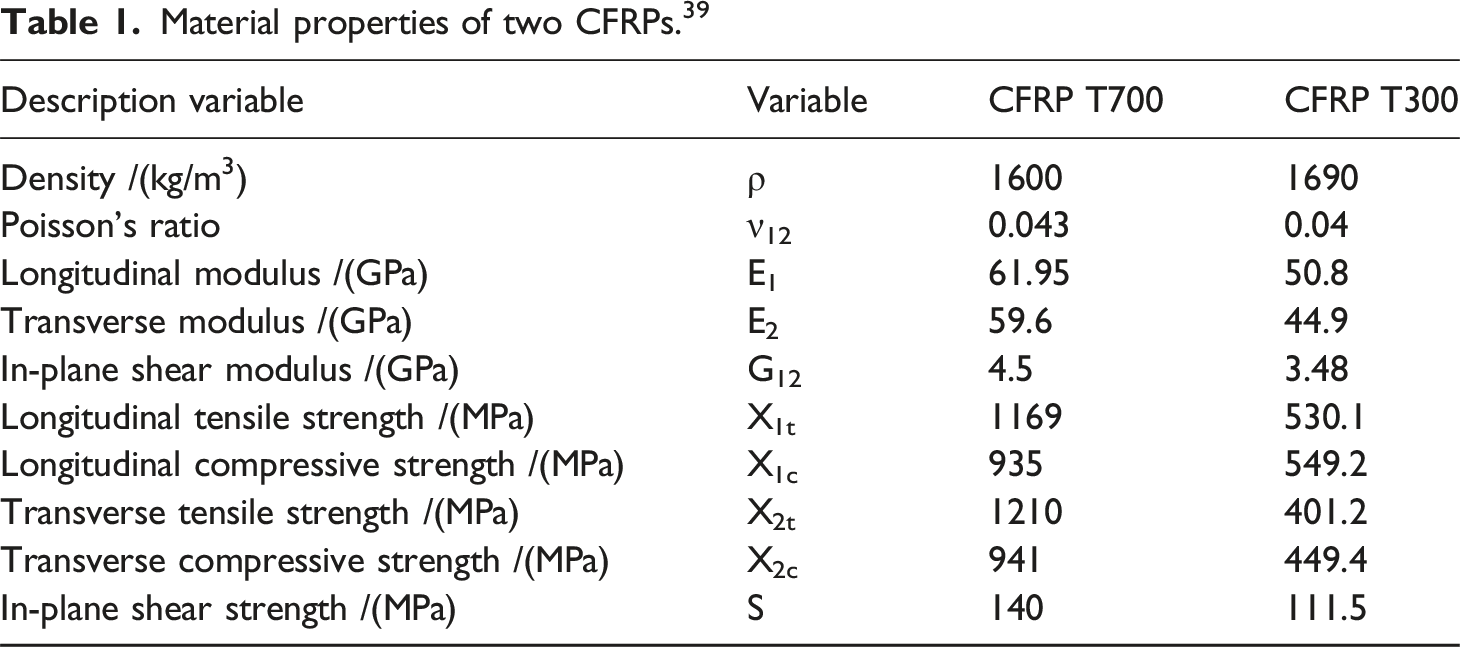
The sandwich tubes with foldcores are made from carbon fibre-reinforced polymer (CFRP) material and comprise two cylindrical inner and outer tubes with a foldcore in between, as shown in Figure 1. Both cylindrical tubes and the foldcore were manufactured using four plies [0°]4 of T700 (Shanxi Zhongsheng Tianze Co Ltd, China) and T300 (Shanxi Zhongsheng Tianze Co Ltd, China) woven carbon/epoxy prepregs respectively, where 0° in the ply stacking sequence indicates the axial direction (direction 1 shown in Figure 3) of the sandwich tube, and the CFRP material properties are from our previous work,
33
as shown in Table 1. Note that the material 1 direction of the cylindrical inner/outer tubes and foldcore is along the axial direction of the tube, while 2 and three material directions are oriented circumferentially and radially.39,77–79 (a) Internal view of the full diamond specimen, (b) complete schematic diagram of the full diamond specimen, (c) schematic diagram illustrating the geometric relationships of the full diamond configuration. Material properties of two CFRPs.
39
The assembly is shown in Figure 2. The inner and outer straight cylindrical tubes were constructed through the hot press moulding technique, as shown in Figure 2(a), and the fabrication process of inner and outer tubes involves manufacturing a polycarbonate inner mould and two half-cylindrical aluminium outer moulds (secured by bolts), laying out the prepregs and curing at room temperature. The foldcore was manufactured by vacuum bag technology with female and male moulds, as shown in Figure 2(b), and the fabrication process includes machining the aluminium moulds, laying out the dry woven fabrics, securing two moulds with bolts, injecting the epoxy resin within the vacuum bag, and curing at room temperature. The assembling process involves cleaning, drilling 3 mm diameter through-holes at the contact points between the foldcore and the inner tube, polishing the 5- Schematic diagram of the mold of the straight tube and the foldcore. (a) inner and outer straight tubes mold to manufacture the straight tubes by hot press moulding technique, (b) the full-diamond pattern foldcore mold to manufacture the foldcores by vacuum bag technology, (c) the image of the full-diamond mold, (d) the image of the sandwich tube specimen with full-diamond foldcore.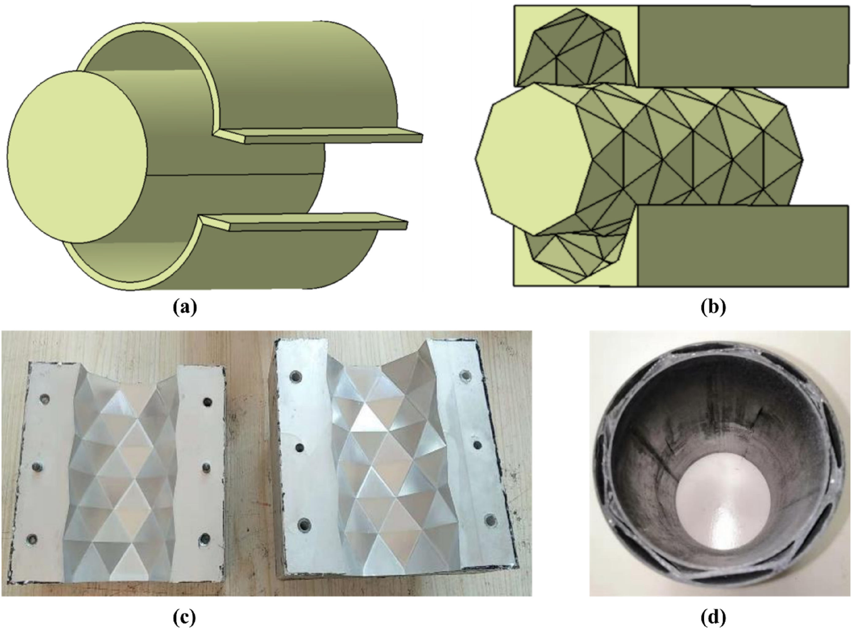
The dimension of the specimen is shown in Figure 1(b) and 1(c). The radius of the inner and outer tube denotes
Numerical model
Material mechanical properties of cohesive elements. 39
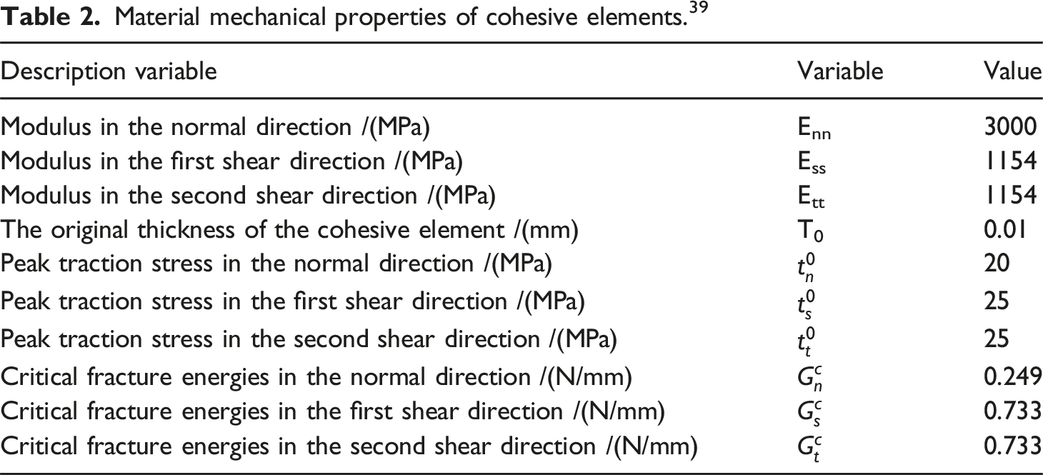
The FE numerical models and the boundary conditions of both loading cases are shown in Figure 3, three parts are tied together using the Tie constraint, as shown in Figure 3(a). The boundary conditions for the three-point bending test were set as follows in Figure 3(b): face-to-face contact was applied between the loading platen and the outer tube. Tie constraints are applied to the contact surfaces between the clamping ends and the bottom support and between two clamping ends and the outer tube. The bottom supports were fully constrained. Global general contact was applied for other regions. The loading platen, clamping ends, and bottom support were all defined as rigid bodies. During the three-point bending process, a downward displacement Details of FE model of the foldcore sandwich tube under the three-point bending test and transverse compression test. (a) Contact relationships in the finite element model of the full diamond configuration, each part is made by four plies of CFRP with the orientation being 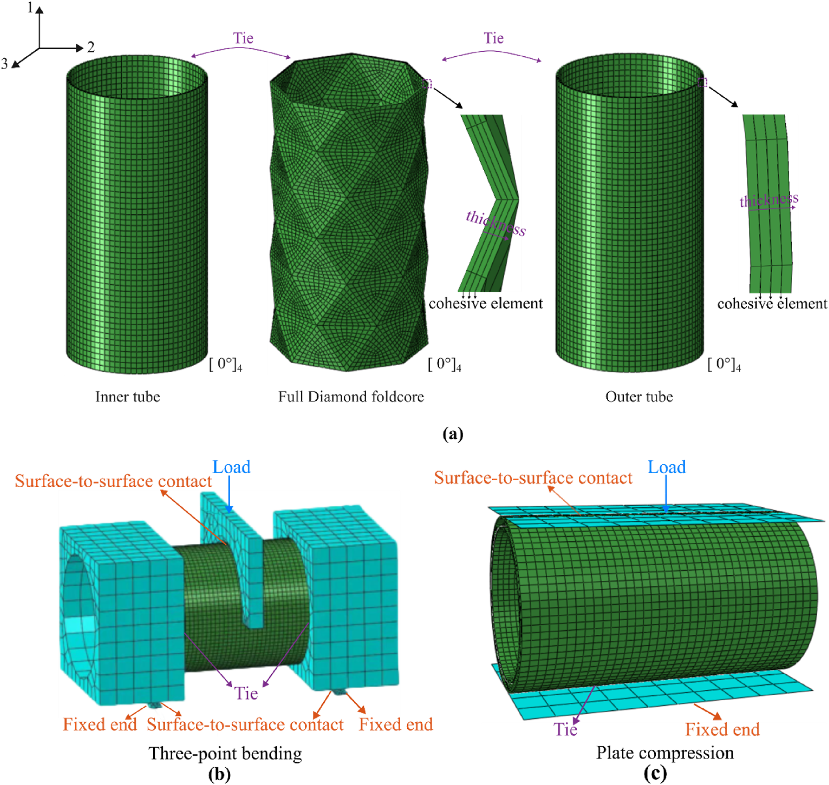
Validation of FE model
Due to the complexity of the finite element boundary conditions in the three-point bending condition, only this experiment was employed to validate the finite element model. As shown in Figure 3(b), the advantage of the setup of the three-point bending experimental tests is to maintain a linear contact between the half-ring-shaped loading head and the sandwich tube, thereby reducing local stress concentration. The fitting type between the two clamping ends and the outer tube is an interference fit. The rationale behind this design is to avoid stress concentration through the surface-to-surface contact formed by two clamping ends of the fixture. The experimental tests were conducted on a MTS universal testing machine (CMT-5105, MTS, maximum load capacity: 50 kN). During the experiment, the loading rate of the head was set to 1.0 mm/min (ASTM D790 standard). The lower two support heads were fixed, while the upper head was compressing downward.
The experimental process of the three-point bending test is illustrated in Figure 4(a). As the loading head applies load, the outer tube of the sandwich structure is first subjected to compression. Notably, at s = 4 mm, a significant bulging phenomenon occurs in the area near the loading head with a slight decrease of reaction force, indicating the local buckling failure of the carbon fibre outer tube and localized matrix shear failure of the foldcore. After that, the overall structure continues to bear the load during the densification of the foldcore, with the reaction force gradually increasing. At s = 8 mm, the entire sandwich tube remains stable without catastrophic failure, although the buckling failure region has expanded and the foldcore exhibited significant shear failure at the loading head and at the bonding interfaces with the outer tube, it still effectively supports the load. The compressive failure of the sandwich tube and the force-displacement results from the experiments and FE models are depicted in Figure 4(b), which exhibit good agreement. Local buckling and crushing occur in the contact area with the heading load, and some longitudinal cracks appear in the inner tube of the sandwich structure (along the height of the sandwich tube). However, there is no global buckling. And the simulation results accurately replicate the post-bending deformation and the indentation shape. Note that there is currently a trend in experimental testing to conduct only one test to evaluate each design condition for economic purposes. Naturally, the available instrumentation and equipment enable a more accurate measurement of the dimensions, material properties, loads and displacements, decreasing the scatter in the results. Here, experiments of two specimens are carried out, and the scatter in the results is considered to be acceptable, indicating the validation of the numerical model of the sandwich structures with foldcore. (a) Comparison between the process of three-point bending experiment and finite element simulation and main damage model of foldcore (shear damage) of the corresponding state of the loading process, (b) comparison of force-displacement curves between three-point bending experiment and finite element simulation.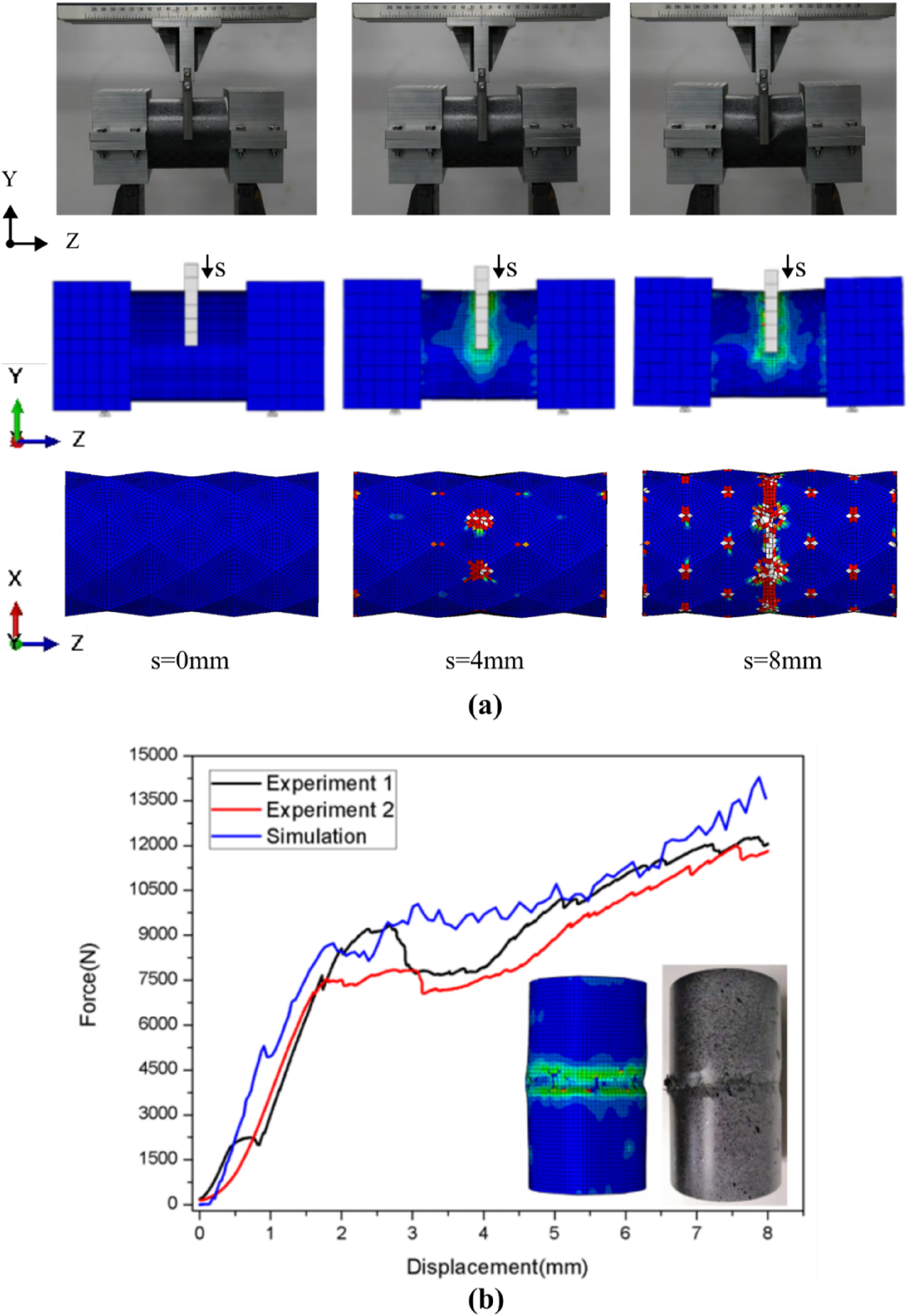
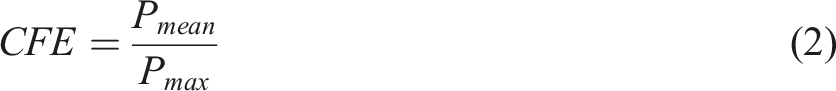
Two parameters are introduced to assess the transverse energy absorption performance of the composite sandwich tubes: the average specific energy absorption (SEA) and the crushing force efficiency (CFE), as expressed below.17,18,39,40,42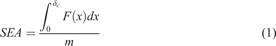
Design process of the geometric foldcore configurations
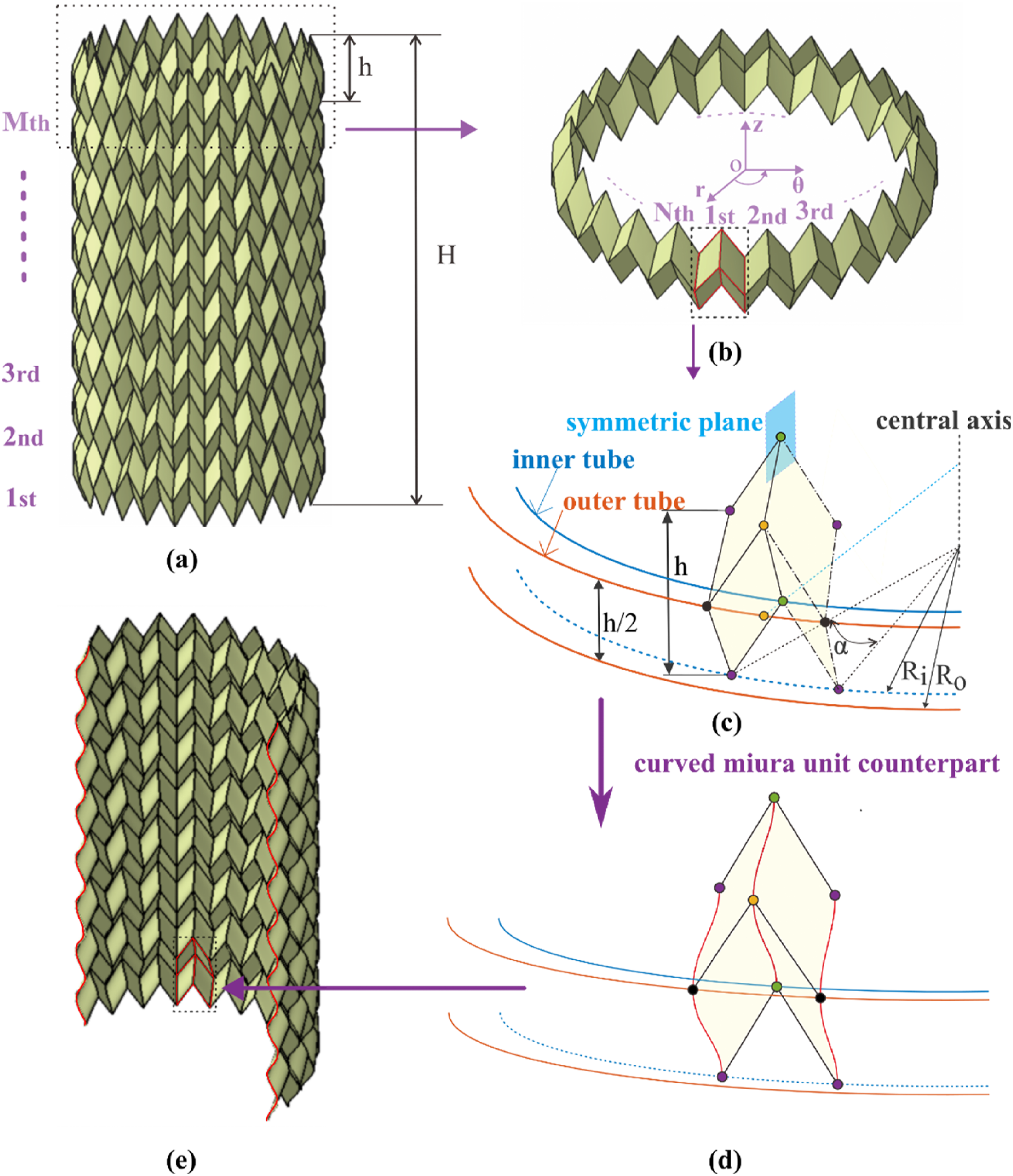
The parametric study investigates the effects of foldcore configurations and main parameters on the energy absorption performance using the validated numerical model. In this section, the design process of 8 different origami-inspired foldcores is introduced. The selected foldcore configurations are: straight/curved-creased axial Miura (SAM/CAM), straight/curved-creased circumferential Miura (SCM/CCM), straight/curved-creased diamond (SD/CD), straight/curved-creased Kresling (SK/CK). As shown in Figure 5(b), the foldcore tubes are designed by assembling unit cells into a basic module (a ring-shape layer) and translating the basic module along the centre axis to build the whole model, all the parameters of the foldcore tubes below are described in the global cylindrical coordinate system, with the original point The design process of the straight/curved-creased axial Miura (SAM/CAM) pattern-based foldcore. (a) the SAM foldcore, which consists of 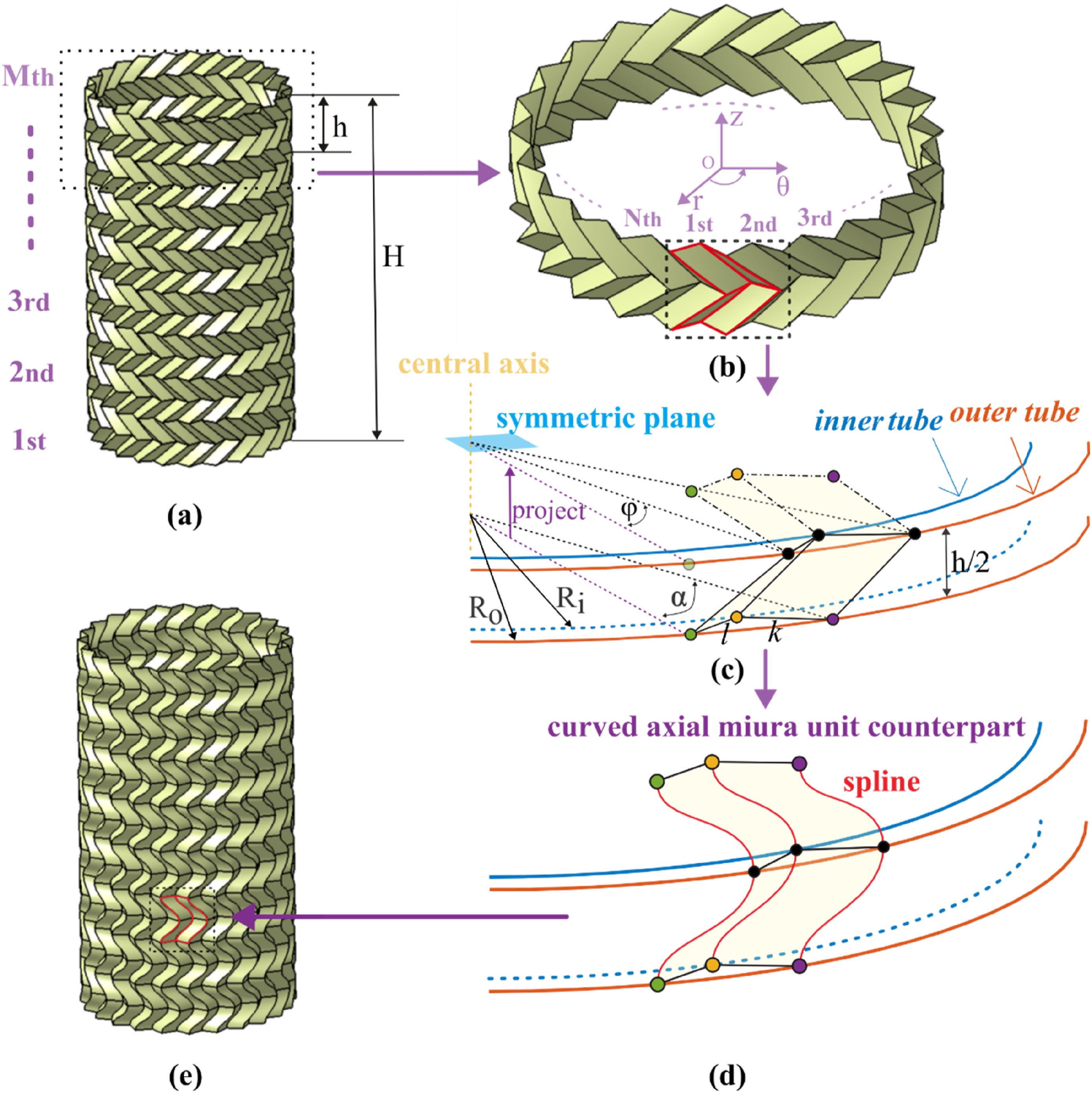
Straight/curve-creased axial miura foldcore
Figure 5(a) is a schematic diagram of the straight-creased axial Miura (SAM) foldcore (the inner and outer tubes are not shown), which is made by stacking the SAM basic module (Figure 5(b)) along the tube axis. Eight parameters in total could define the unit cell and the whole SAM foldcore: 
Straight/curve-creased circumferential miura foldcore
As shown in Figure 6, the circumferential Miura and the axial Miura are similar in geometry but different in orientation. Figure 6(a)and (b) respectively show a complete straight-creased circumferential Miura (SCM) foldcore (inner and outer tubes are not shown) and a basic module, The design process of the straight/curved-creased circumferential Miura (SCM/CCM) pattern-based foldcore. (a) SCM foldcore, which consists of 
According to the angle
Straight/curve-creased diamond foldcore
The straight-creased Diamond (SD) foldcore is composed of identical trapezoids. As shown in Figure 7(a), The design process of the straight/curved-creased diamond (SD/CD) pattern-based foldcore. The angle across the circumferential direction of the short edge and the long edge denotes 
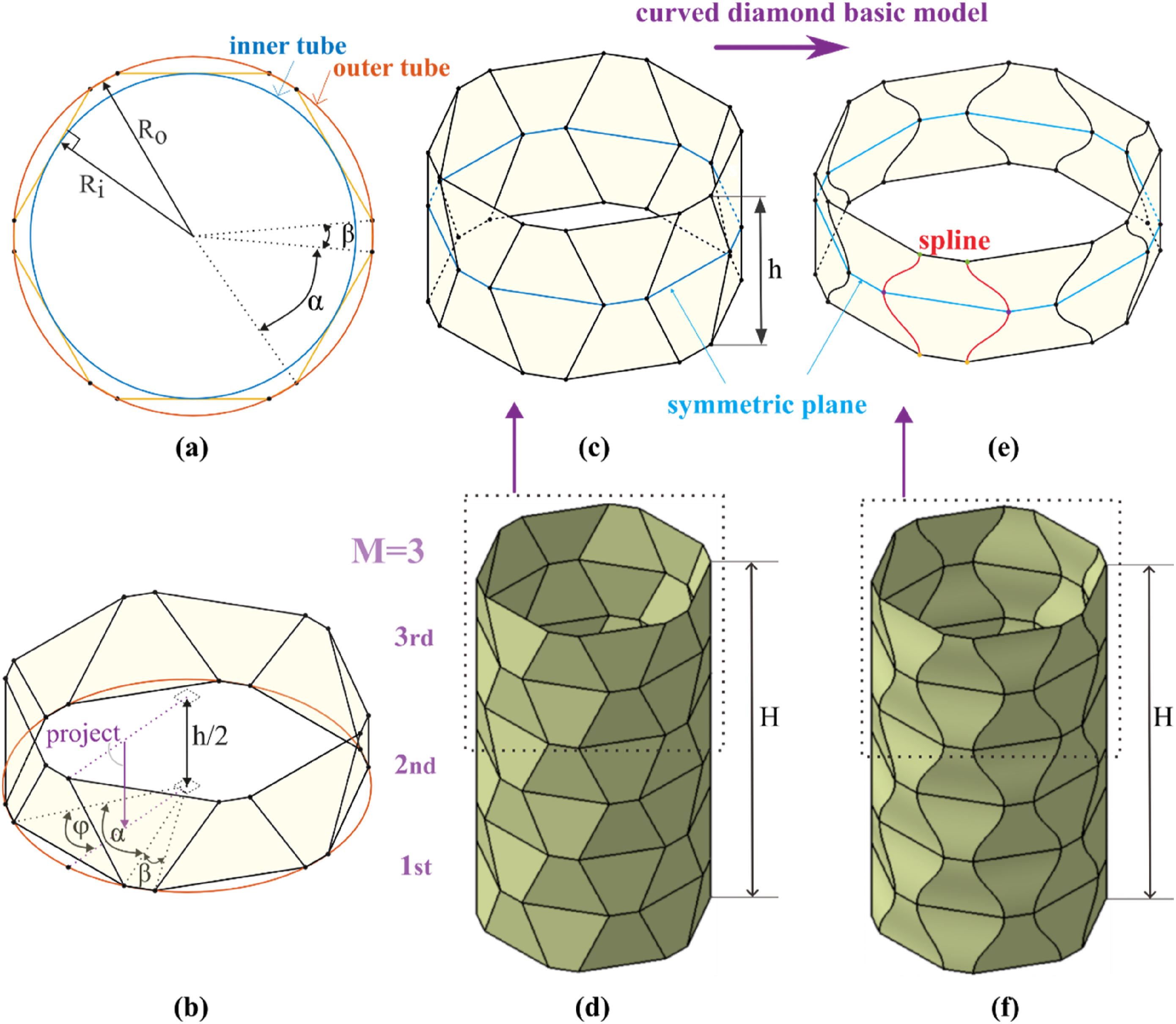
The geometric design process is as follows. As shown in Figure 7(c), the top and the bottom outlines of a module are polygons of
Straight/curved-creased kresling foldcore
The straight-creased Kresling (SK) foldcore exhibits similarities to the diamond foldcore in its design process, involving translation, rotation, and connection of a polygon along the central axis of the tube because of the geometric constraint. As shown in Figure 8(a), the outer tube corresponds to the circumscribed circle of the polygon. The design process of the Kresling pattern-based foldcore. (a) The geometric relationship between the Straight-creased Kresling (SK) foldcore and the inner and outer tubes. The inner tube is inscribed at the middle point of the diagonal line at the height of 


The results of the parameter study
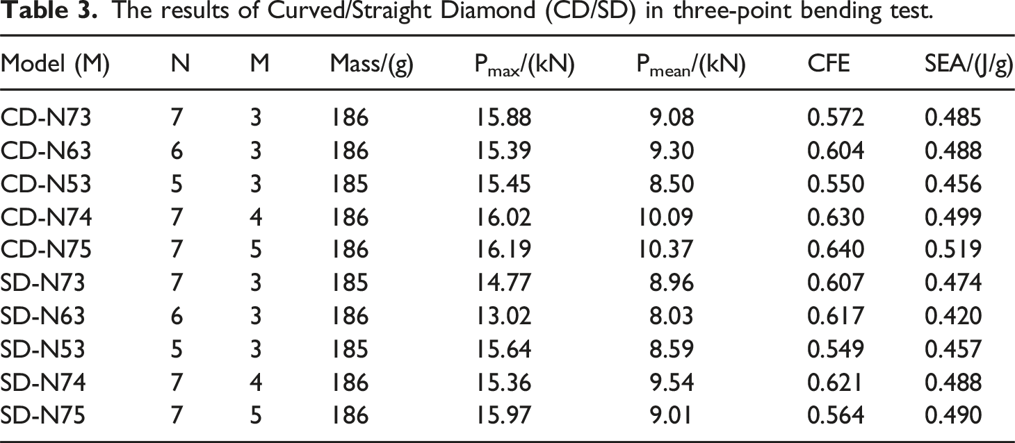
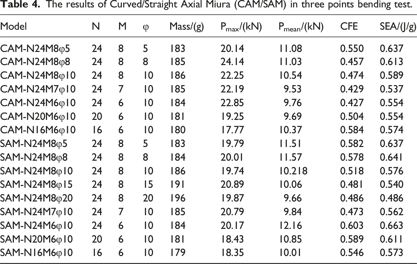
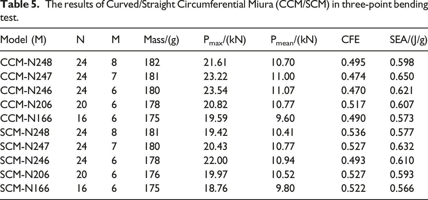
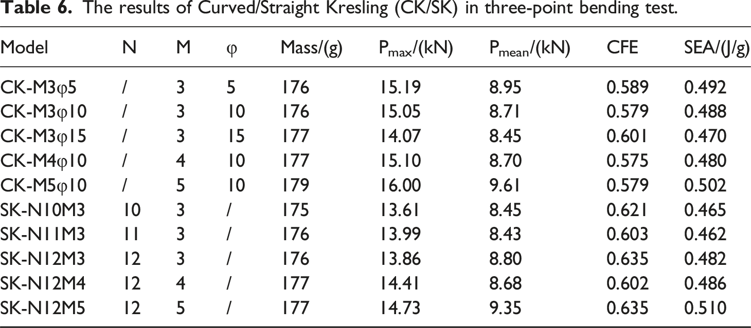
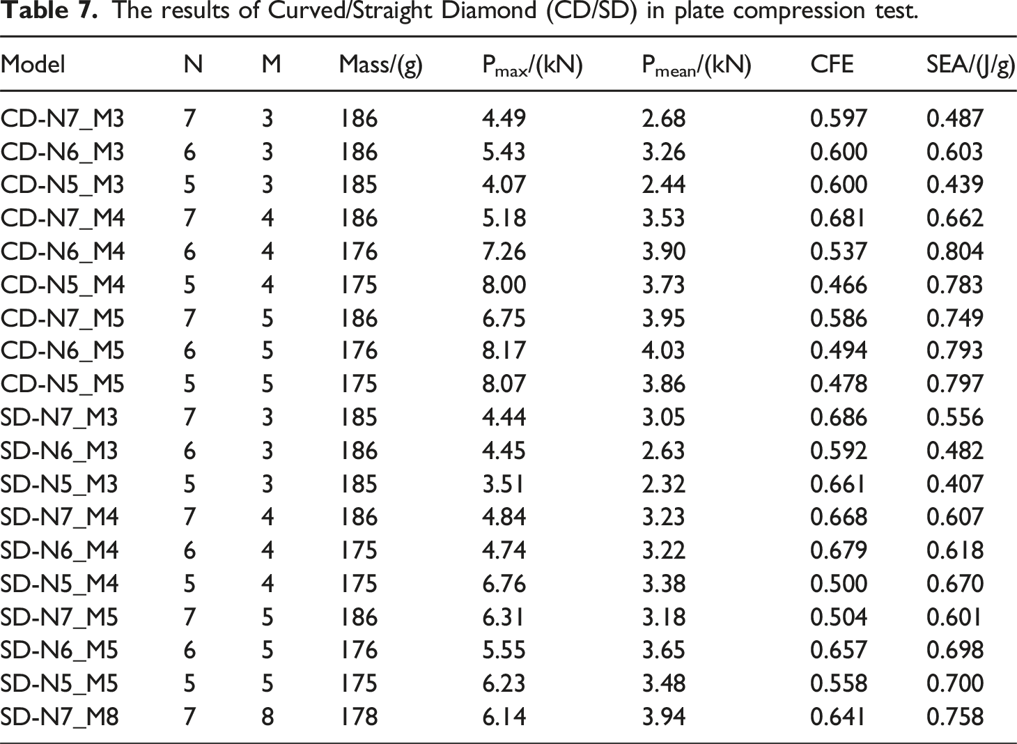
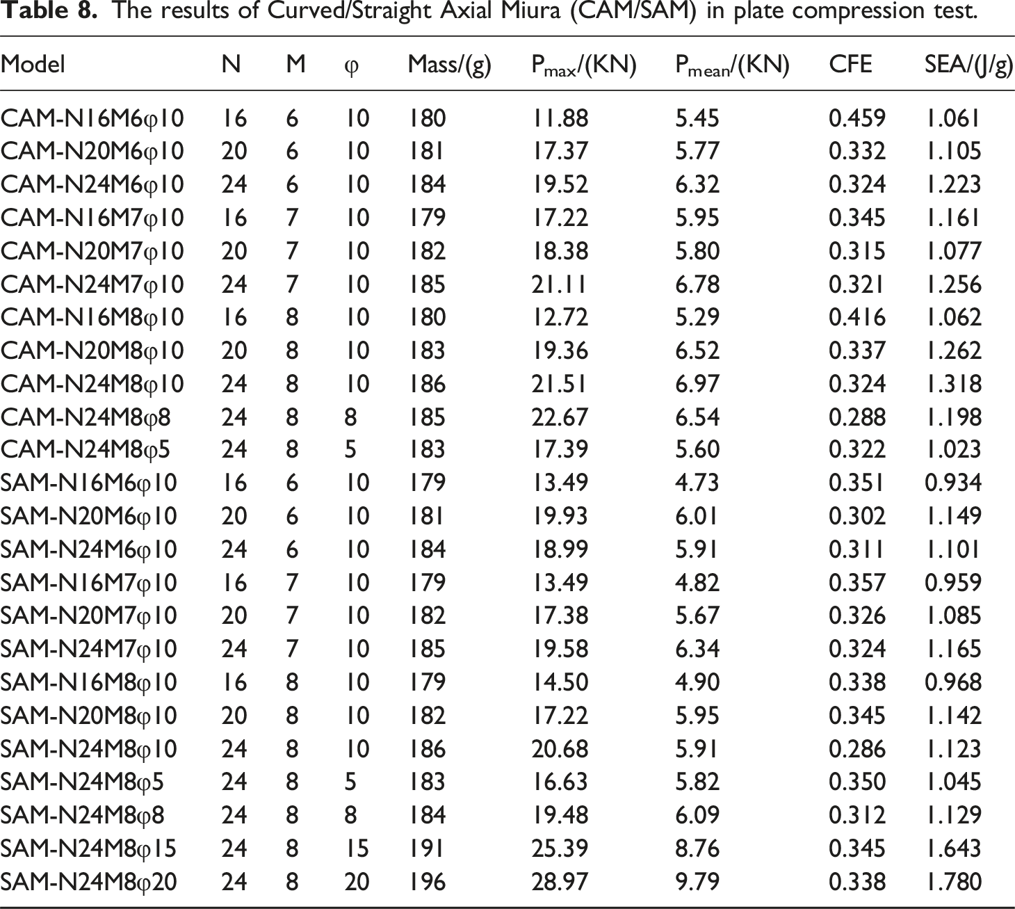
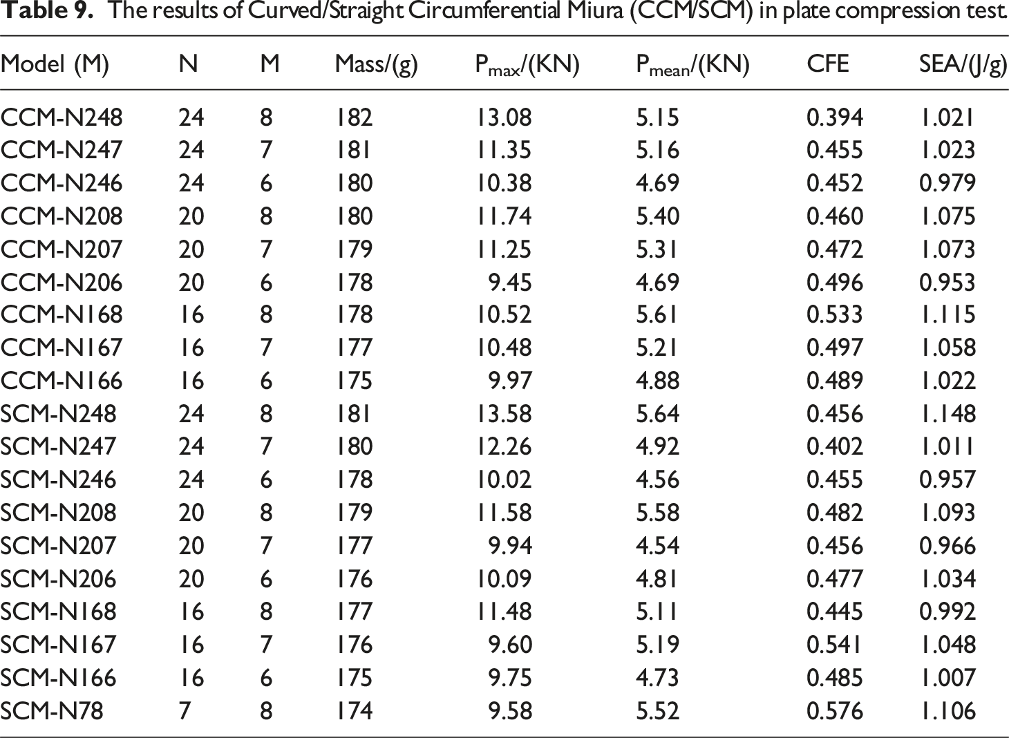
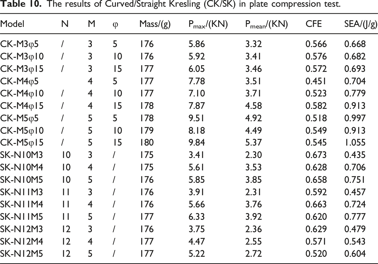
In this section, a parametric study is carried out to investigate the effects of foldcores patterns and geometric parameters on the transverse mechanical properties of composite sandwich tubes under three-point bending and transverse compression conditions. Results of straight-creased axial Miura (SAM), curved-creased axial Miura (CAM), straight-creased circumferential Miura (SCM), curved-creased circumferential Miura (CCM), straight-creased diamond (SD), curved-creased diamond (CD), straight-creased Kresling (SK), curved-creased Kresling (CK) are shown. Representative schematic diagrams of each configuration are illustrated in Figure 9. All the results of SEA and CFE values with geometric parameters of unit cells are shown in Tables 3–6 for three-point bending tests and Tables 7–10 for transverse compression tests. Representative schematic diagrams of eight distinct configurations employed for parametric study. The “zigzag” line is defined above, the number of N and M influences the zigzag line and further affects the energy absorption capacity of the sandwich tube structures, which will be detailed in the later section. The results of Curved/Straight Diamond (CD/SD) in three-point bending test. The results of Curved/Straight Axial Miura (CAM/SAM) in three points bending test. The results of Curved/Straight Circumferential Miura (CCM/SCM) in three-point bending test. The results of Curved/Straight Kresling (CK/SK) in three-point bending test. The results of Curved/Straight Diamond (CD/SD) in plate compression test. The results of Curved/Straight Axial Miura (CAM/SAM) in plate compression test. The results of Curved/Straight Circumferential Miura (CCM/SCM) in plate compression test. The results of Curved/Straight Kresling (CK/SK) in plate compression test.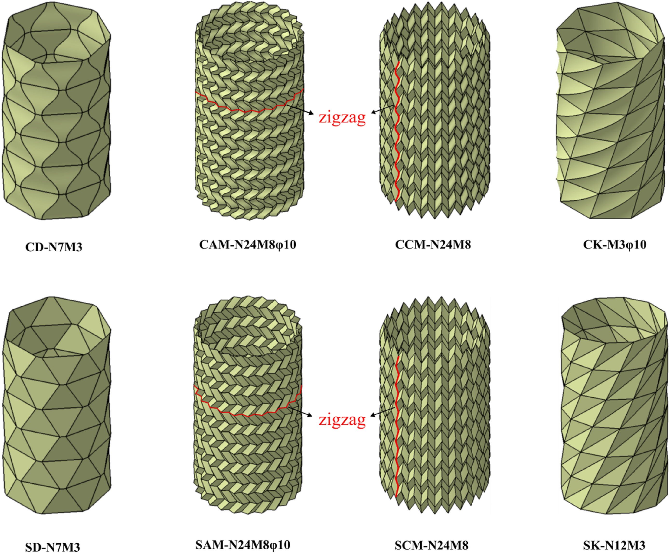
The results of the parameter study of foldcores under three-point bending
Figure 10(a)–(d) present the simulation results of the force-displacement curves for ten different The three-point bending results of the parametric study of the sandwich tube structure with straight/curved-creased diamond foldcore. Force displacement curves for (a) models N7M5, N7M4, and N7M3, and (b) models N7M3, N6M3, and N5M3 of the straight-creased diamond foldcore sandwich tube, with 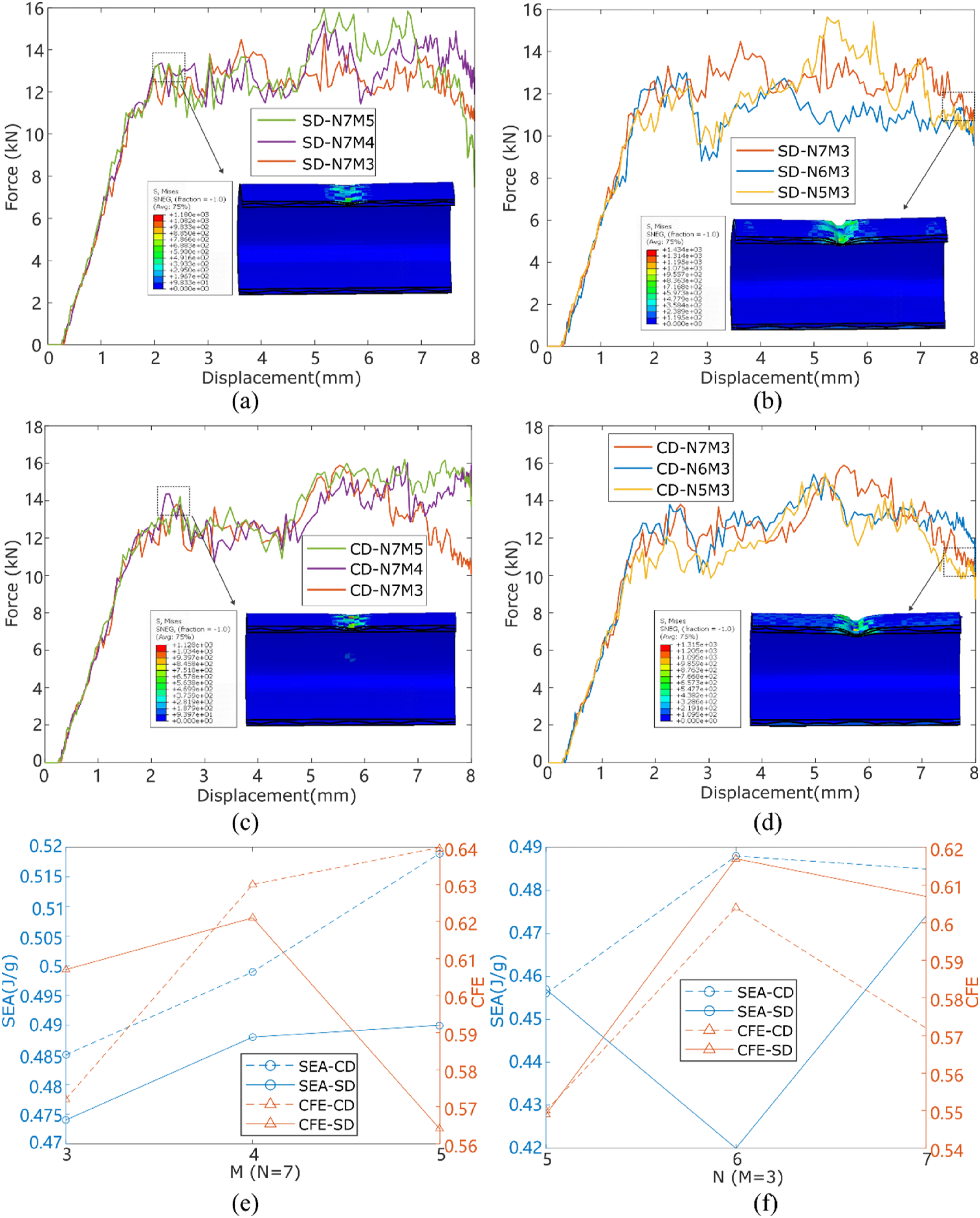
Next, the force-displacement curves of nine models with straight-creased axial Miura (SAM) foldcore and seven models of curved axial Miura (CAM) foldcore are presented in Figure 11(a)–(f), respectively. As shown in Figure 11(g), an increase in the twist angle The three-point bending results of the parametric study of the sandwich tube structure with straight/curved-creased axial Miura foldcore. Force displacement curves for (a) models N24M8φ5, N24M8φ8, N24M8φ10, N24M8φ15, and N24M8φ20, and (b) models N24M8φ10, N24M7φ10, and N24M6φ10, and (c) models N24M6φ10, N20M6φ10, and N16M6φ10 of the Straight-creased axial Miura foldcore sandwich tube, with 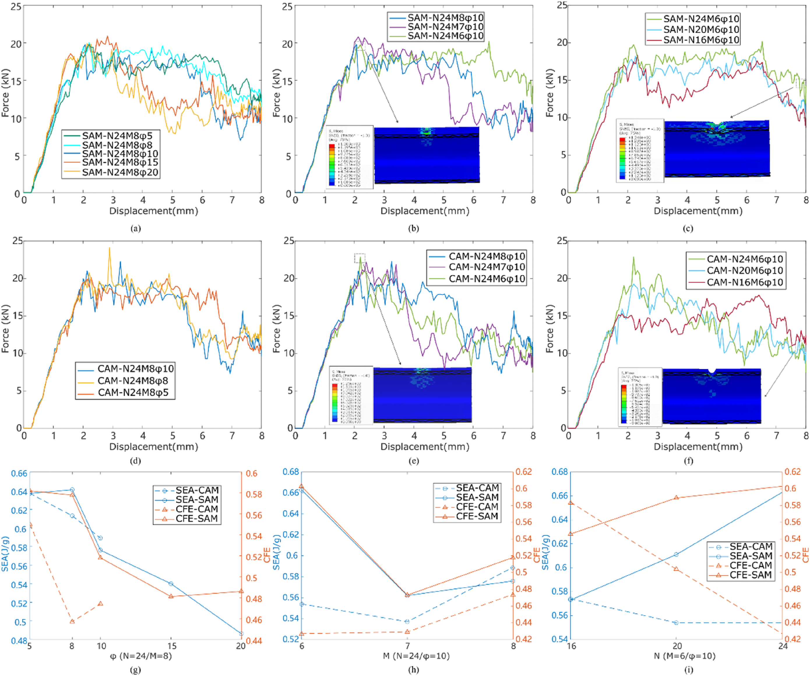
The force-displacement curves of five different parameter configurations for straight/curved-creased circumferential Miura (SCM/CCM) foldcore tubes are plotted in Figure 12. From Figures 12(a) and 12(c), it can be observed that the variation in The three-point bending results of the parametric study of the sandwich tube structure with straight/curved-creased circumferential Miura foldcore. Force displacement curves for (a) models N24M8, N24M7, and N24M6, and (b) models N24M6, N20M6, and N16M6 of the Straight-creased circumferential Miura foldcore sandwich tube, with 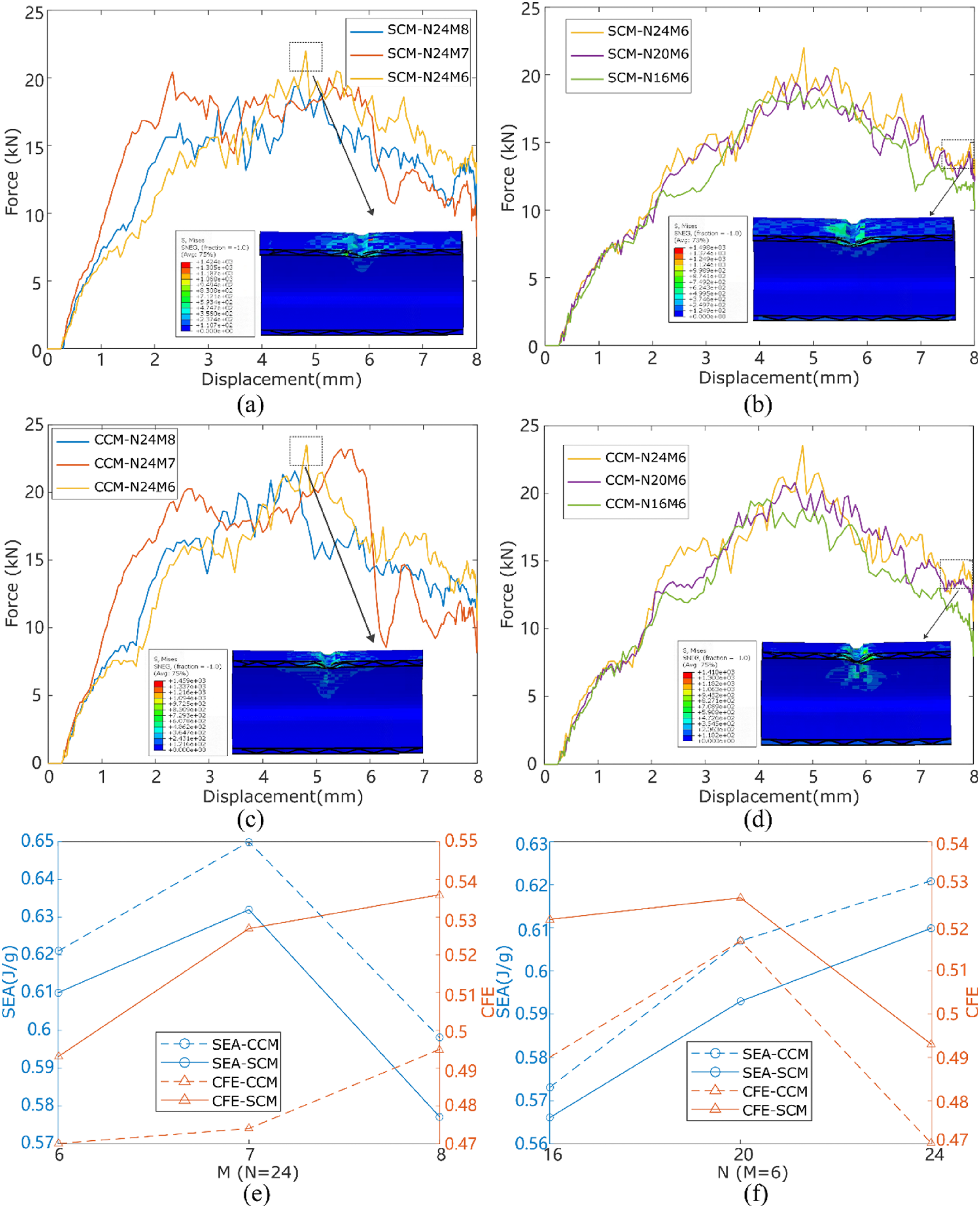
Figure 13 presents the force-displacement curves of straight/curved-creased Kresling foldcore sandwich tubes with different parameters. As shown in Figure 13(b), the peak force of SK increases with the increase of The three-point bending results of the parametric study of the sandwich tube structure with straight/curved-creased Kresling foldcore. Force displacement curves for (a) models N10M3, N11M3, and N12M3, and (b) models N12M3, N12M4, and N12M5 of the Straight-creased Kresling foldcore sandwich tube, with 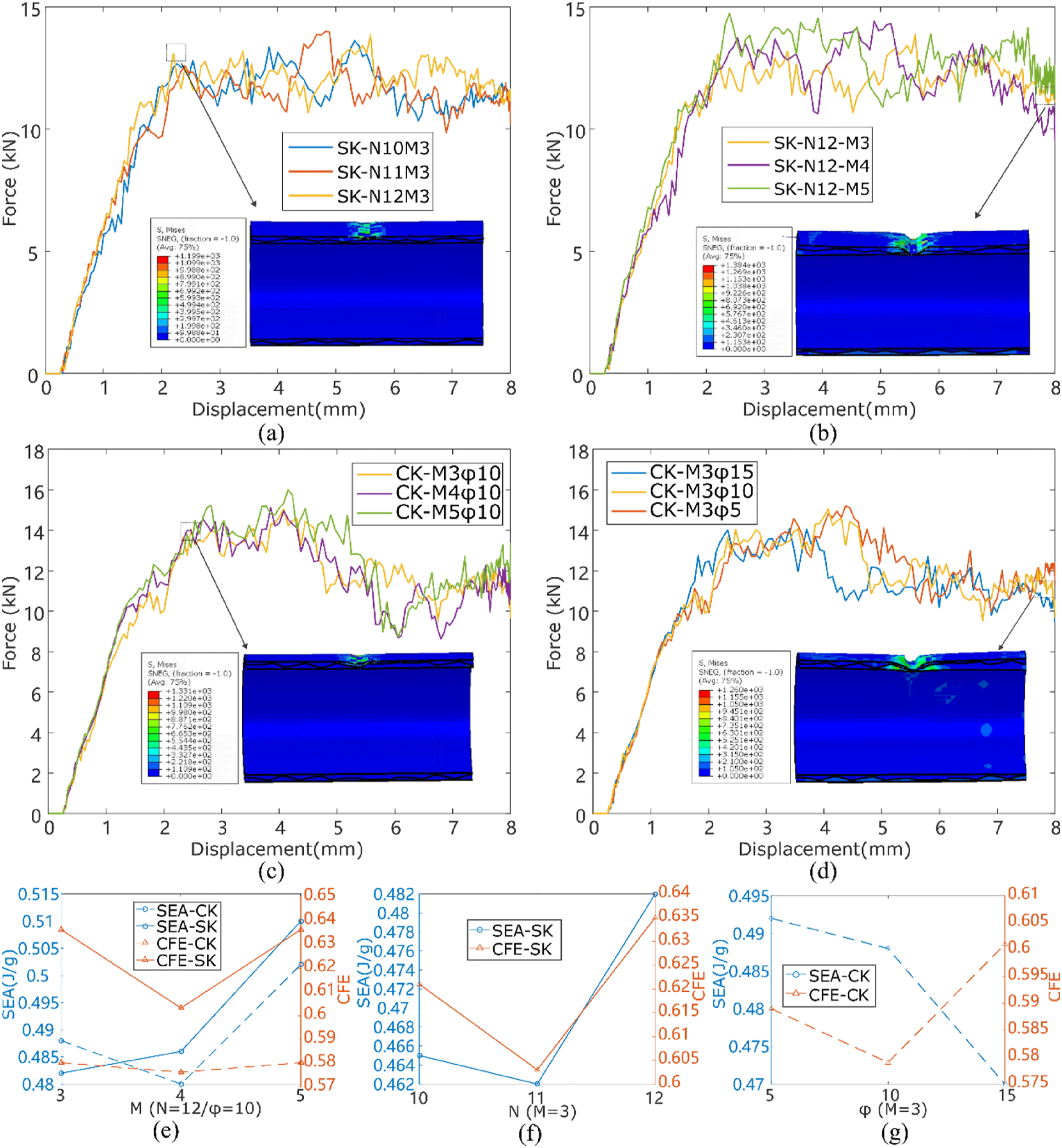
For the three-point bending tests, the bending stiffness and the energy absorption capacity (SEA) of the Miura patterns are higher than the diamond and Kresling counterparts. One main reason might be the fact that the contact region between the Miura foldcore and tubes is formed by zigzag lines, whereas the contact region between the diamond/Kresling foldcore and tubes is mostly formed by straight lines. However, the crushing force efficiency (CFE) value of diamond and Kresling foldcores is generally higher than that of circumferential and axial Miura foldcores, which indicates a steadier and less fluctuation of the force during the loading process.
The damage modes of the sandwich tubular structures with diamond, circumferential Miura, axial Miura, and Kresling foldcores under three-point bending conditions exhibit similarities, are shown in Appendix A.1-A.4. Structurally, none of the foldcores experienced global buckling failure. Instead, localized areas in contact with the indenter displayed a certain degree of tension/ compression matrix damage and shear damage. The main energy absorption mechanisms under the condition of compression for each foldcore material will be discussed in detail in Section 4.2.
The results of the parameter study of foldcores under plate compression
In this section, a parametric study of the aforementioned models under plate compression is conducted, and all results are presented in Tables 7–10. Note that the energy absorption capacity is the main investigated index under the transverse compression condition. Figure 14(a) to 14(d) illustrate the simulation results of force-displacement curves for eleven different combinations of The plate compression results of the parametric study of the sandwich tube structure with straight/curved-creased diamond foldcore. Force displacement curves for (a) models N7M5, N7M4, and N7M3, and (b) models N7M3, N6M3, and N5M3 of the Straight-creased diamond foldcore sandwich tube, with 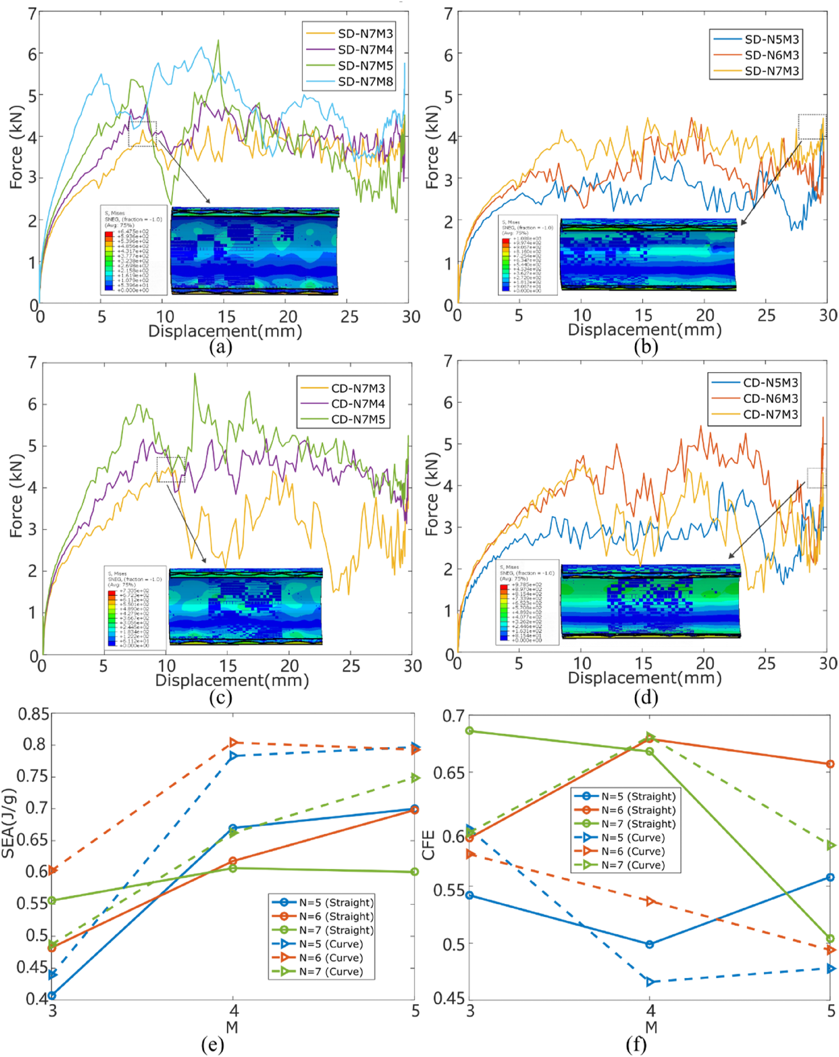
Appendix A.5.-A.6 present the damage modes of the SD and CD foldcores under plate compression conditions, respectively. The structural failure mode is characterized by global buckling, with the compressed cross-sectional shapes exhibiting an elliptical form. This indicates that the sandwich tubes with diamond foldcore do not undergo shear deformation in the xy-plane. For the CD foldcore, the primary material damage occurs at the intersection points where it connects with the outer tube and in the collapse regions where the outer tube deforms plastically and contacts the core, leading to matrix damage in tension/compression, and shear damage. In contrast, the SD core exhibits a smaller and less severe damage area, but lower energy absorption, indicating that the curves effectively transfer the load, allowing for more efficient utilization of the foldcore material and enhancing the energy absorption capacity of the structure.
Figure 15(a)–(f) present the force-displacement curves of straight-creased axial Miura (SAM) and curved-creased axial Miura (CAM) under different parameters. It can be observed that the AM configuration generally exhibits higher peak forces, with force-displacement curves typically showing two higher peaks, where the second peak is slightly lower than the first one, followed by a gradual reduction and plateauing of the reactive forces. Figure 15(g) reveals that increasing the in-plane twist angle The plate compression results of the parametric study of the sandwich tube structure with straight/curved-creased axial Miura foldcore. Force displacement curves for (a) models N24M8φ5, N24M8φ8, N24M8φ10, N24M8φ15, and N24M8φ20, and (b) models N24M8φ10, N24M7φ10, and N24M6φ10, and (c) models N24M6φ10, N20M6φ10, and N16M6φ10 of the Straight-creased axial Miura foldcore sandwich tube, with 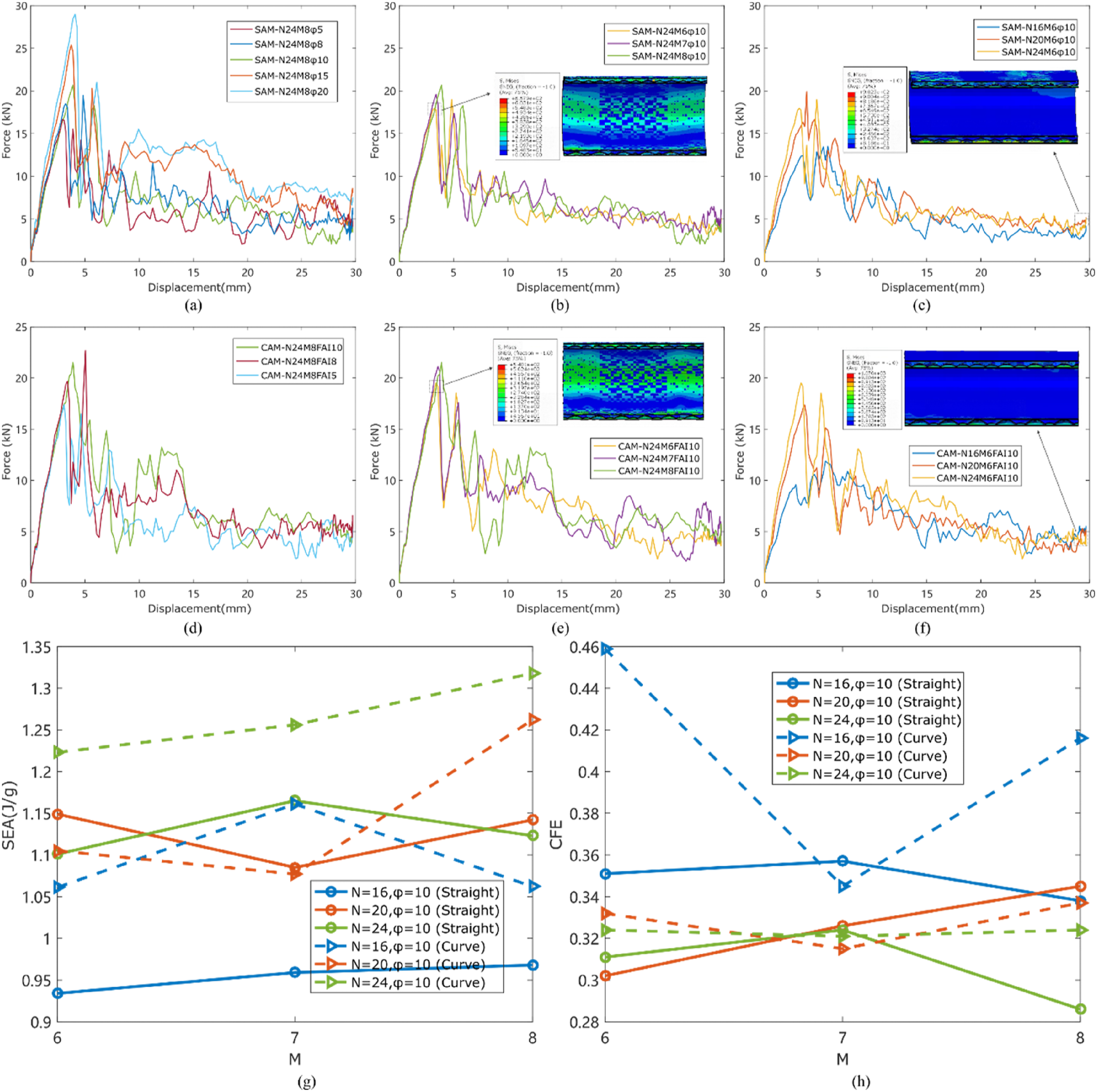
The damage modes of the SAM and CAM foldcores are detailed in Appendix A.7.-A.8. Structurally, the failure modes are characterized by global buckling accompanied by partial delamination. Due to their geometric characteristics, shear deformation occurs in the cross-section during compression. The primary damage modes of the foldcore material include matrix damage in tension/compression and shear damage. The main areas of material damage are the zigzag regions in contact with the outer tube (along the axial direction of the tube), while there is almost no damage along the zigzag line direction (circumferential direction of the tube). This is because the presence of the zigzag lines helps to distribute the load transferred from the outer tube across the entire core, significantly enhancing the energy absorption efficiency of the material and structure.
Figure 16(a)–(d) reveal the force-displacement curves under transverse compression of CM foldcore, which share a similar pattern with AM foldcore but they generally exhibit significantly lower peak forces. As seen in Figures 16(a) and 16(c), increasing The plate compression results of the parametric study of the sandwich tube structure with straight/curved-creased circumferential Miura foldcore. Force displacement curves for (a) models N24M8, N24M7, and N24M6, and (b) models N24M6, N20M6, and N16M6 of the Straight-creased circumferential Miura foldcore sandwich tube, with 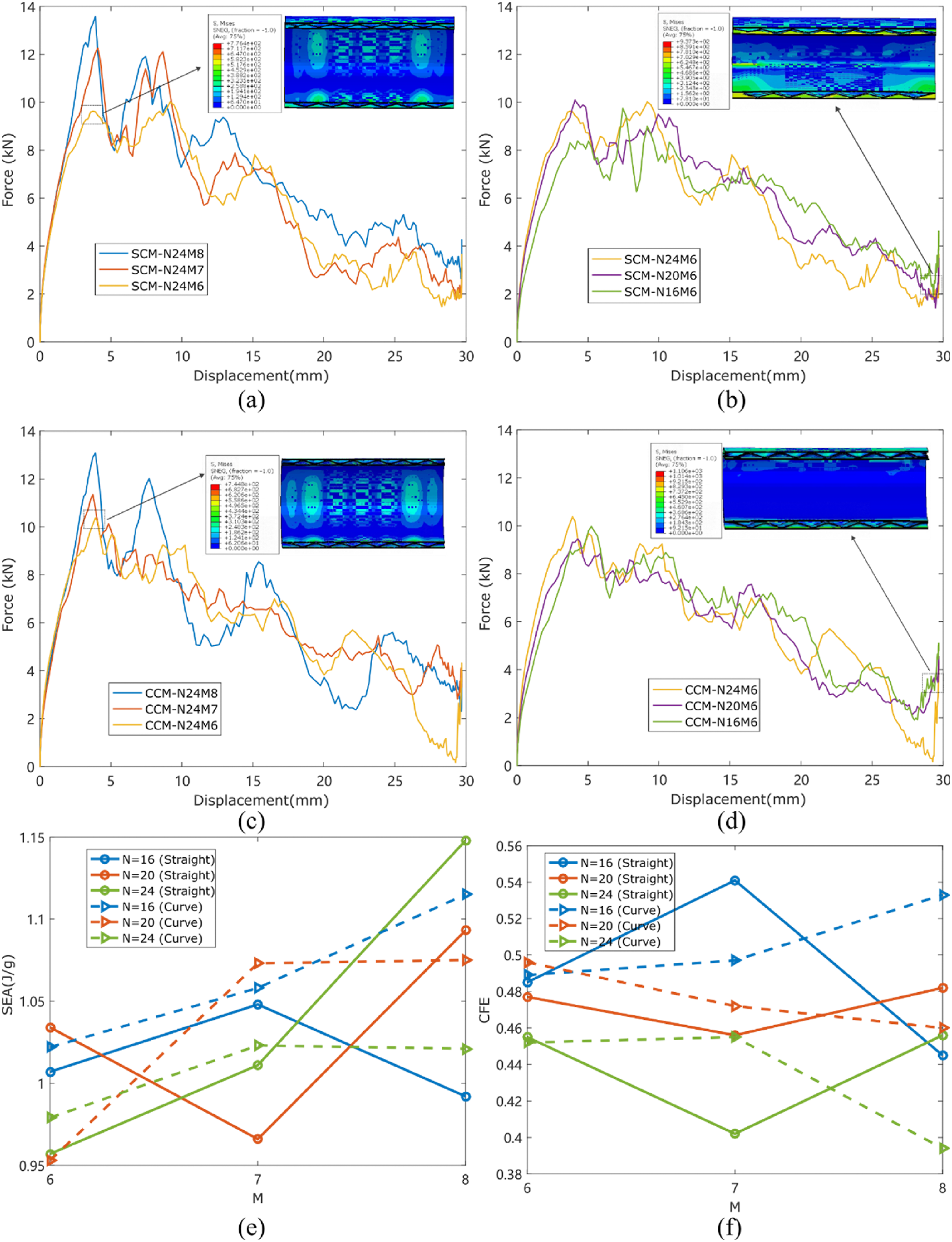
Appendix A.9.-A.10 present the damage modes of the SCM and CCM foldcores. Similar to the AM foldcores, their geometric characteristics result in shear deformation of the core cross-section during compression, contributing to energy absorption. The primary material damage modes are matrix damage in tension/compression, and shear damage. The presence of the zigzag lines helps to distribute the load transferred from the outer tube across the entire core and to the inner tube, enhancing the energy absorption capability of the structure.
As shown in Figure 17(a)–(d), the force-displacement curves for the Kresling model exhibit a distinct pattern compared to the Miura-pattern models but are similar to the diamond-pattern models. These curves do not feature exceptionally high peak forces maintain a relatively constant level after the initial peak and exhibit a significant decline in the latter half of the compression process. For straight-creased Kresling (SK), increasing both The plate compression results of the parametric study of the sandwich tube structure with straight/curved-creased Kresling foldcore. Force displacement curves for (a) models N10M3, N11M3, and N12M3, and (b) models N12M3, N12M4, and N12M5 of the straight-creased Kresling foldcore sandwich tube, with 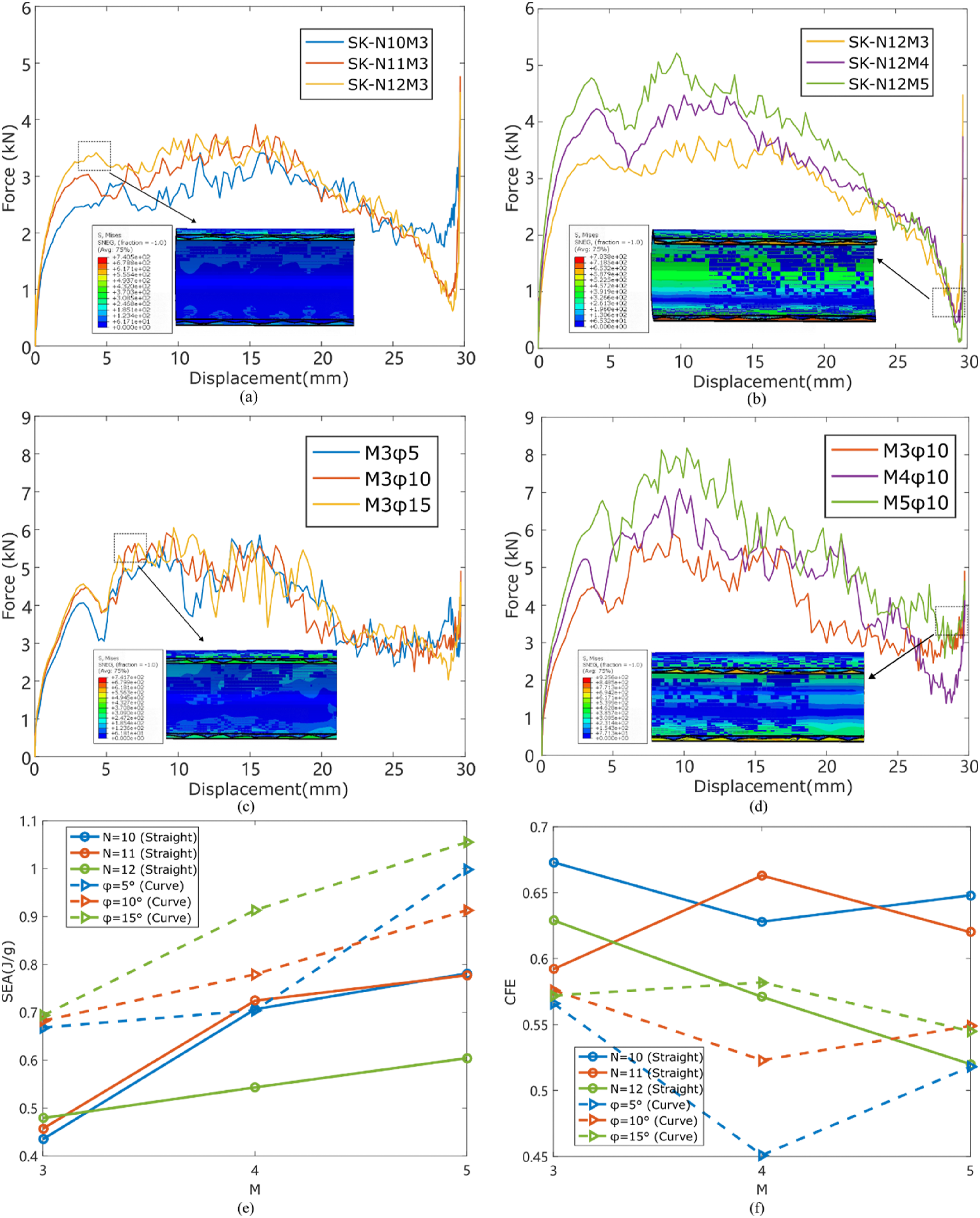
Appendix A.11.-A.12 show the damage modes of the SK and CK foldcores. It can be observed that during compression, the CK core exhibits shear deformation in the cross-section, contributing to energy absorption. The damage extent of the CK foldcore is also greater than that of the SK foldcore, demonstrating that the CK foldcore more effectively transfers the load throughout the entire foldcore structure. The SEA results also confirm that the energy absorption performance of the CK foldcore is superior to that of the SK foldcore.
Based on the results of the parametric study, it was found that the energy absorption capability of different core structures is primarily influenced by two factors: 1. The ability of the geometric configuration to transfer the load to the inner tube, e.g., the supporting structures of the zigzag lines formed by the geometric characteristics of the Miura foldcore; 2. The ability of the geometric configuration to distribute the load to other areas of the core structure, that is, whether the majority of the material could participate into the deformation process.
Sandwich tubes with Miura configurations exhibit better specific energy absorption (SEA) capability per unit mass under both loading conditions, compared to their counterparts. One could assume that the primary reason is that the Miura configuration efficiently transfers the load to the inner tube via the zigzag lines, thus making efficient use of the sandwich structure characteristics. Additionally, the Miura core itself undergoes shear deformation within the cross-section during compression, which effectively distributes the load throughout the core, thereby maximizing the material’s participation in energy absorption.
In contrast, the diamond and Kresling configurations, upon receiving the load transferred by the outer tube, lack the direct zigzag line mechanism to transfer the load to the inner tube as seen in the Miura configuration. Instead, they can only transfer the load to the inner tube through their planar elements, resulting in significantly reduced load transfer efficiency and consequently lower energy absorption performance. And, the curved configurations of the diamond and Kresling foldcores can better enhance their ability to distribute the load to other parts of the core, thereby improving their transverse energy absorption capabilities.
Optimization of the energy absorption capability of SAM and SCM
Overall, the sandwich tube structures with Miura-patterned foldcore could provide more stiffness and a higher energy absorption capacity than other foldcore counterparts due to the essence of its structural geometry. Then, the question arises as to whether the assumption that we have earlier on the effect of zigzag lines in contact region on the energy absorption capacity. Here, we chose the straight-creased axial Miura (SAM) and straight-creased circumferential Miura (SCM) pattern to investigate the influence of unit cell types on the lateral energy-absorbing performance of sandwich tubes under transverse compression.
Based on the shape of the projected rectangle area (whose sides are the axial height The optimization design of the sandwich tube with Miura-pattern foldcore. The illustration of various types of (a) straight-creased axial Miura (SAM), (b) straight-creased circumferential Miura (SCM) configuration sandwich tubes. Three types of the unit cell of the foldcore are defined by their shapes of projected area: Type I (a “belt” shape), Type II (a “square” shape), and Type III (a “tower” shape), with a 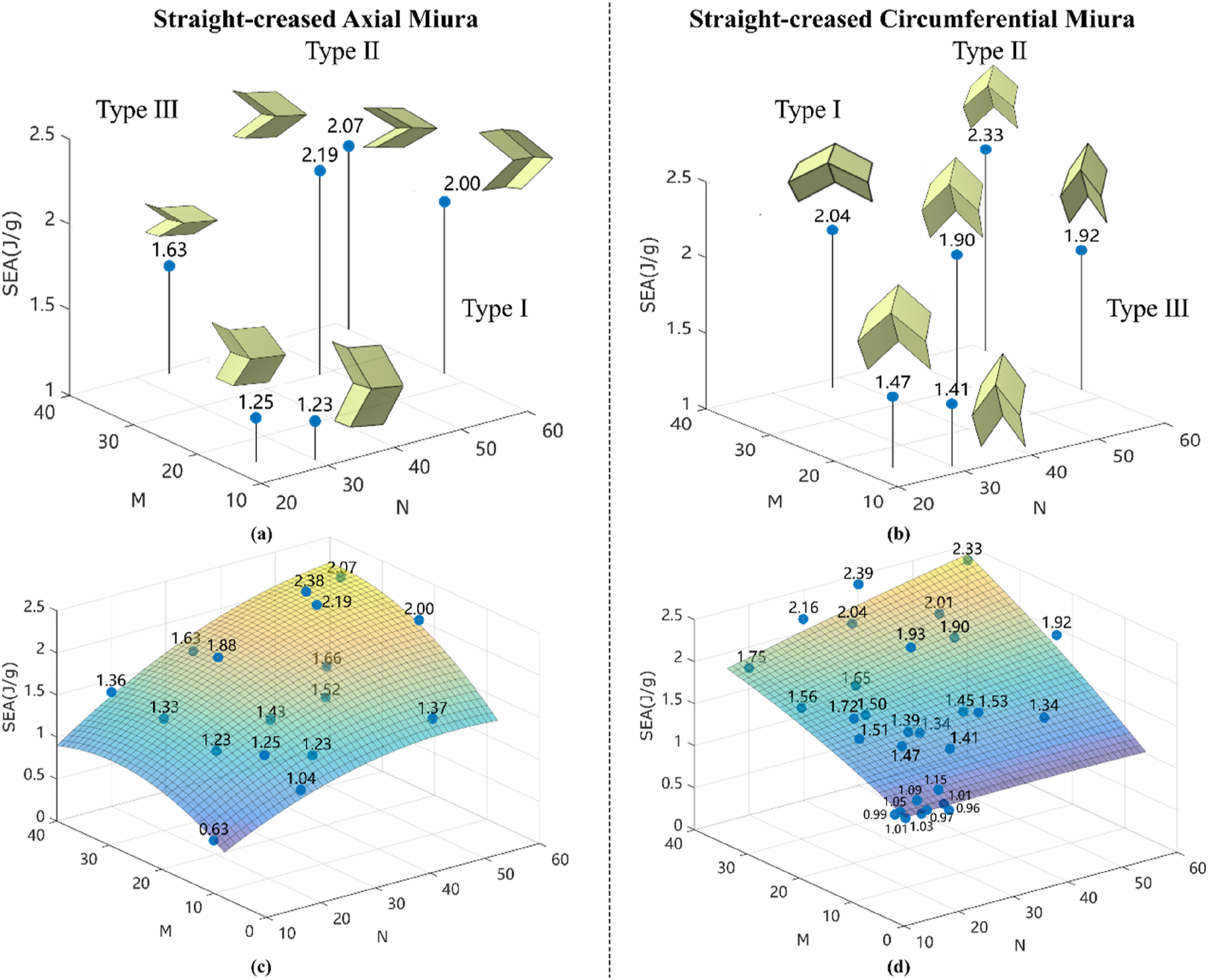
To further quantify the effects of 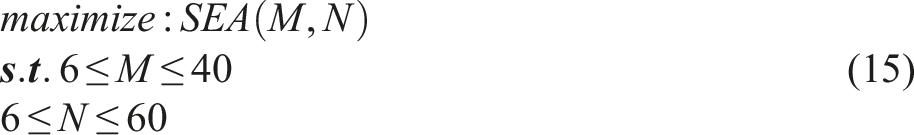
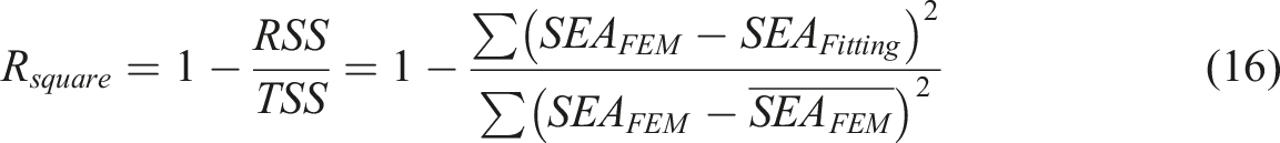
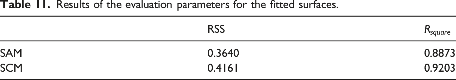
Results of the evaluation parameters for the fitted surfaces.
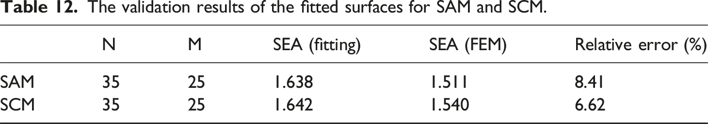
The validation results of the fitted surfaces for SAM and SCM.
Therefore, due to differences in the direction of the zigzag lines (as defined in Figure 9), axial (circumferential) Miura displays higher sensitivity to parameter
Comparison and discussion
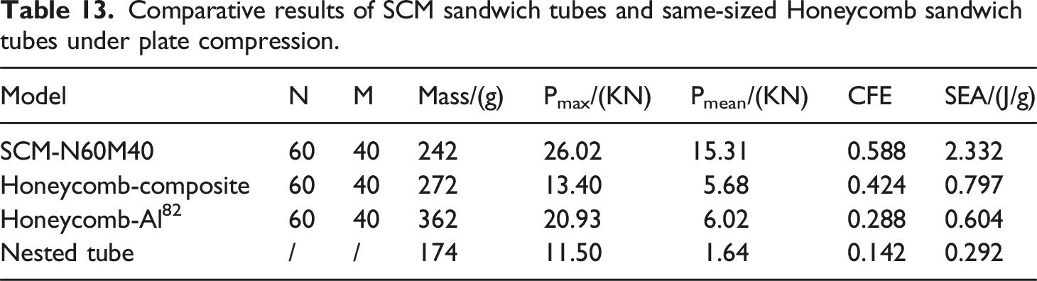
Finally, the Miura-pattern foldcore is compared to the traditional honeycomb core with the same unit cell dimension and the nested tube for the energy absorption capacity. As shown in Figure 19(a), the SCM configuration with the optimized transverse compression energy absorption performance ( (a) Schematic representation of nested tube, two sandwich tubes with honeycomb core (one core material being CFRP T300 and the other being Aluminium) and straight-creased circumferential Miura foldcores sandwich tube with identical unit cell dimensions, the inner and outer tubes of the honeycomb and circumferential Miura sandwich tube structures are not shown for clarity of the figure. (b) force-displacement curves of sandwich tubes with SCM foldcore, composite Honeycomb foldcore, aluminium Honeycomb foldcore and nested tube under transverse compression testing. Comparative results of SCM sandwich tubes and same-sized Honeycomb sandwich tubes under plate compression.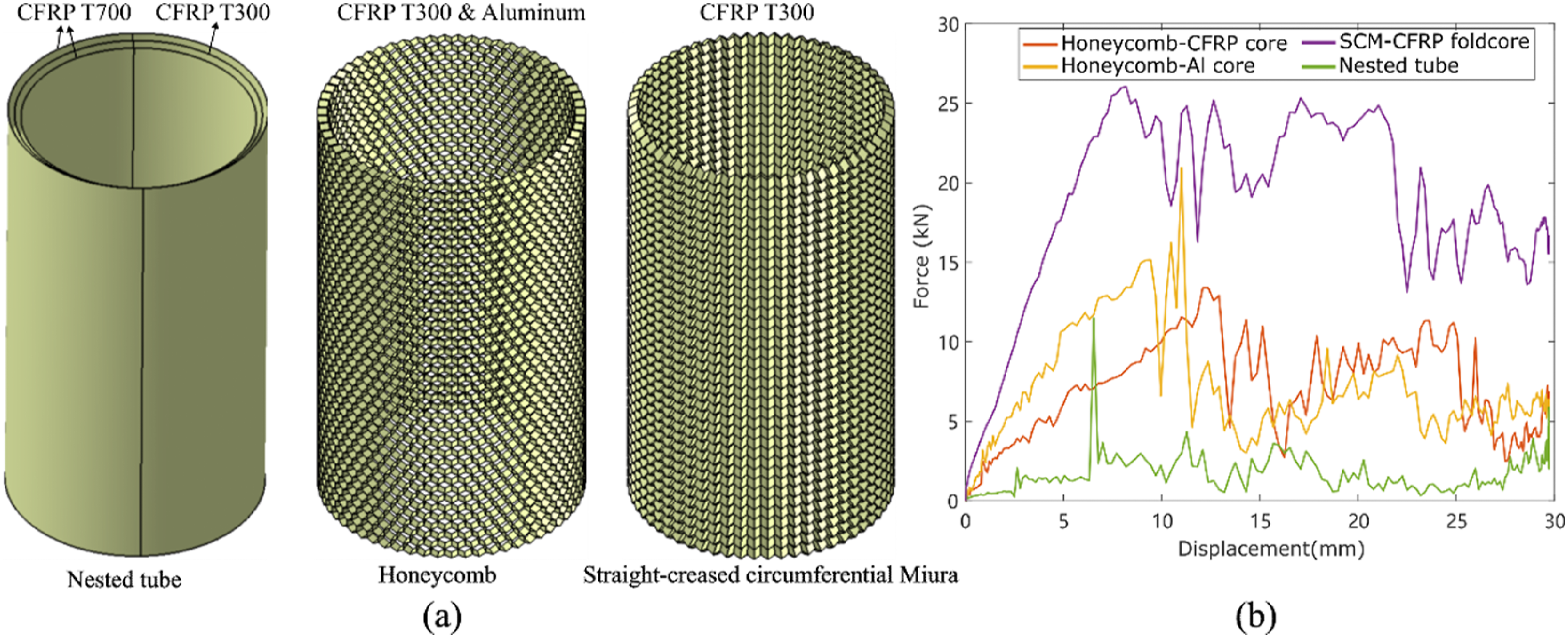
As shown in Figure 20, the damage modes of the foldcore material in the circumferential Miura (CM) structure and the intermediate tube in the nested tube structure demonstrate global buckling. However, the CM structure’s matrix material did not exhibit significant damage, whereas the intermediate tube of the nested tube structure experienced minor matrix damage and shear failure at the interfaces with the inner and outer tubes. Comparison of tension/compression matrix damage and shear damage in the circumferential Miura N60M40 foldcore and the intermediate tube of the nested tube, the figure of the damage mode is the ending state of the loading process.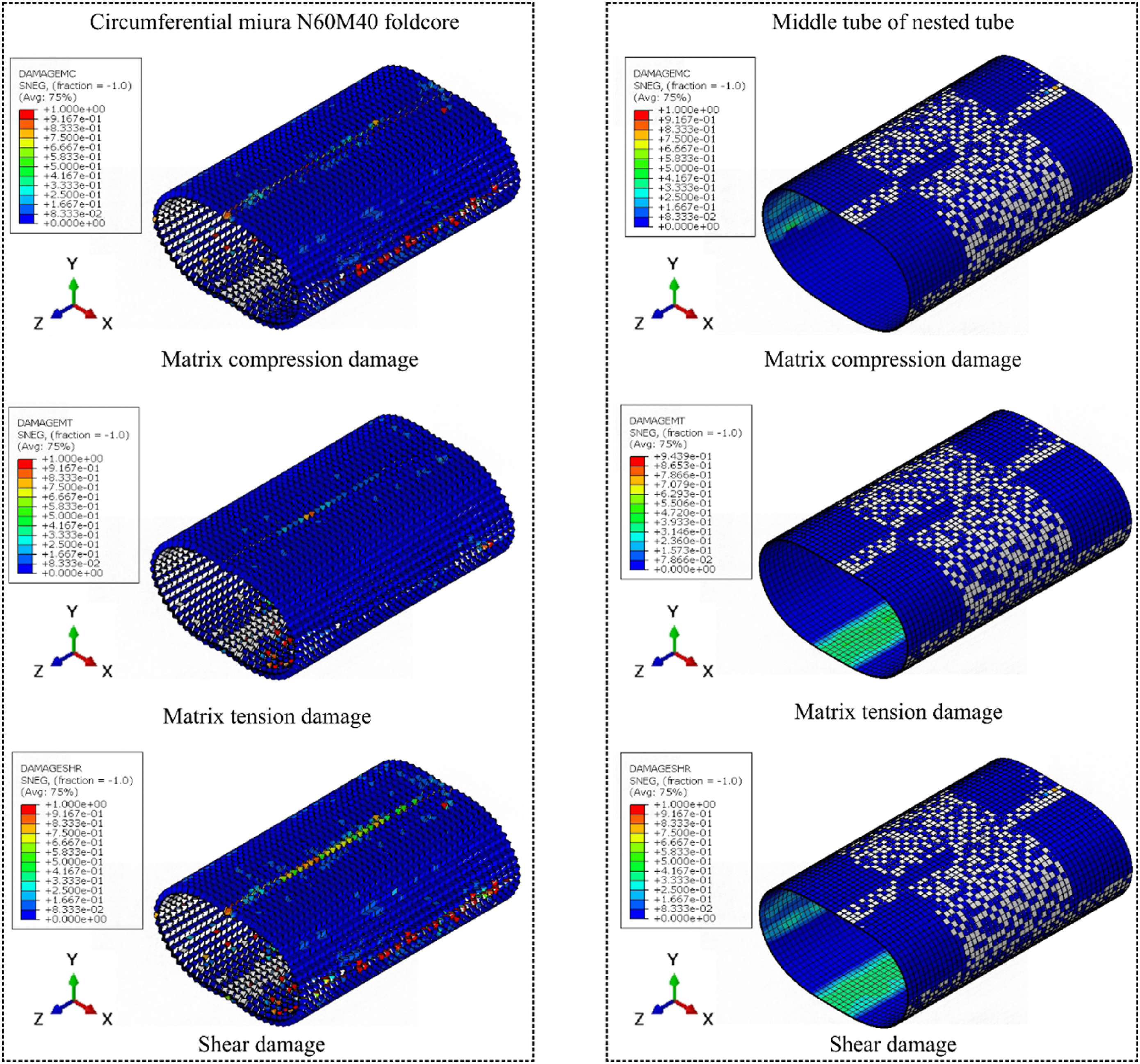
Based on the parametric study analysis, the CM foldcore transfers the load received by the outer tube along the zigzag lines, engaging most of the structure and material in the energy absorption process. The absence of extensive material damage in the CM N60M40 might be attributed to the high density of the Miura unit cells, which disperses the energy without reaching the failure threshold of the material. In contrast, despite the nested tube structure showing only minor localized material damage, the significantly lower load-displacement curve in Figure 19 indicates that most of the material did not contribute to energy absorption compared with the CM foldcore structure.
This underscores the advantages of the origami core: it increases structural support (enhancing stiffness) and transfers the load to the inner tube. The folds can be seen as predefined deformation paths, allowing a greater portion of the material to resist deformation and thereby contributing to the energy absorption process.
Conclusion
This paper presents a comprehensive study of the effects of composite sandwich tube structures with 8 different origami-inspired foldcores (diamond, Kresling, circumferential Miura, axial Miura and their curved-crease counterparts) on the transverse mechanical properties, that is, the energy absorption performance. Specimens are manufactured, and three-point bending-like local compression experiments are carried out to validate the FE numerical. The design process of the foldcore is detailed, and its main parameters are identified. The parametric study and damage mode analysis of the transverse mechanical properties is conducted, the main parameters are studied to understand the effects on the energy absorption capacity, and the comparisons between the SCM foldcore structures with honeycomb core counterparts and nested tubes are made.
The results show that the specific energy absorption (SEA) of Miura configurations is generally higher than diamond and Kresling configurations, exhibiting superior energy absorption performance (higher SEA values): In three-point bending (transverse compression) tests, the average SEA values of the Miura configuration is 0.591 J/g (1.098 J/g), which was 22.9% (78.8%) higher than the average SEA value of 0.481 J/g (0.614 J/g) for diamond and Kresling configurations. This is because the Miura configuration effectively transfers external loads to both the inner tube and other parts of the foldcore, thereby better utilizing the geometric characteristics of the Miura pattern-based structure as the foldcore. The crushing force efficiency (CFE) values of Miura are generally lower than those of diamond and Kresling patterns, which indicates that foldcores with diamond and Kresling patterns have steadier force-displacement curves during deformation: In three-point bending (transverse compression) tests, the CFE value of the Miura configuration is 0.513 (0.471), which was 14.4% (20.8%) lower than the average CFE value of 0.599 (0.595) for diamond and Kresling configurations. For diamond and Kresling sandwich tube structures, it is worth noting that
The work in this paper investigates the quasi-static transverse mechanical properties of sandwich tube structures with foldcores. The design method is systematically provided, and the parametric study is carried out to identify the key factors for different foldcore patterns. Critical insights into the behaviour of these sandwich tube structures with foldcores were revealed by the findings of the study, the Miura pattern foldcore is optimized and a design strategy is given. Hence, the work in this paper could provide a reference for future designs when the transverse mechanical properties are considered, especially for applications/ designs such as under-sea pipes, pressure containers, functional structures (e.g., fuselage in aircraft), etc. Yet the behaviours under impact are not included in the scope of this research. Future avenues would be to investigate the effect of fibre orientation and thermal effects on the transverse modulus and crashworthiness of the composite sandwich tubular structures with foldcores. Also, we will consider exploring the use of new manufacturing techniques and materials with better mechanical properties to produce tubular origami-based foldcore at a lower cost with better performance, which could potentially enable us to conduct extensive physical experiments for further study. Additionally, in conjunction with the work of Li et al. 83 and Wang et al., 36 our study may offer new potential directions for Origami-based TPMS structures.
Footnotes
Acknowledgements
Haitao Ye completed the research at Shanghai Jiao Tong University and has moved to City University of Hong Kong, Tat Chee Avenue, Kowloon, Hong Kong SAR, since completing the research. The authors would like to thank for all the comments received.
Declaration of conflicting interests
The author(s) declared no potential conflicts of interest with respect to the research, authorship, and/or publication of this article.
Funding
The author(s) disclosed receipt of the following financial support for the research, authorship, and/or publication of this article: The financial support from the National Natural Science Foundation of China 52373293 and 51408357 are acknowledged.
Note
Appendix
The damage mode of diamond configuration foldcore material under three-point bending.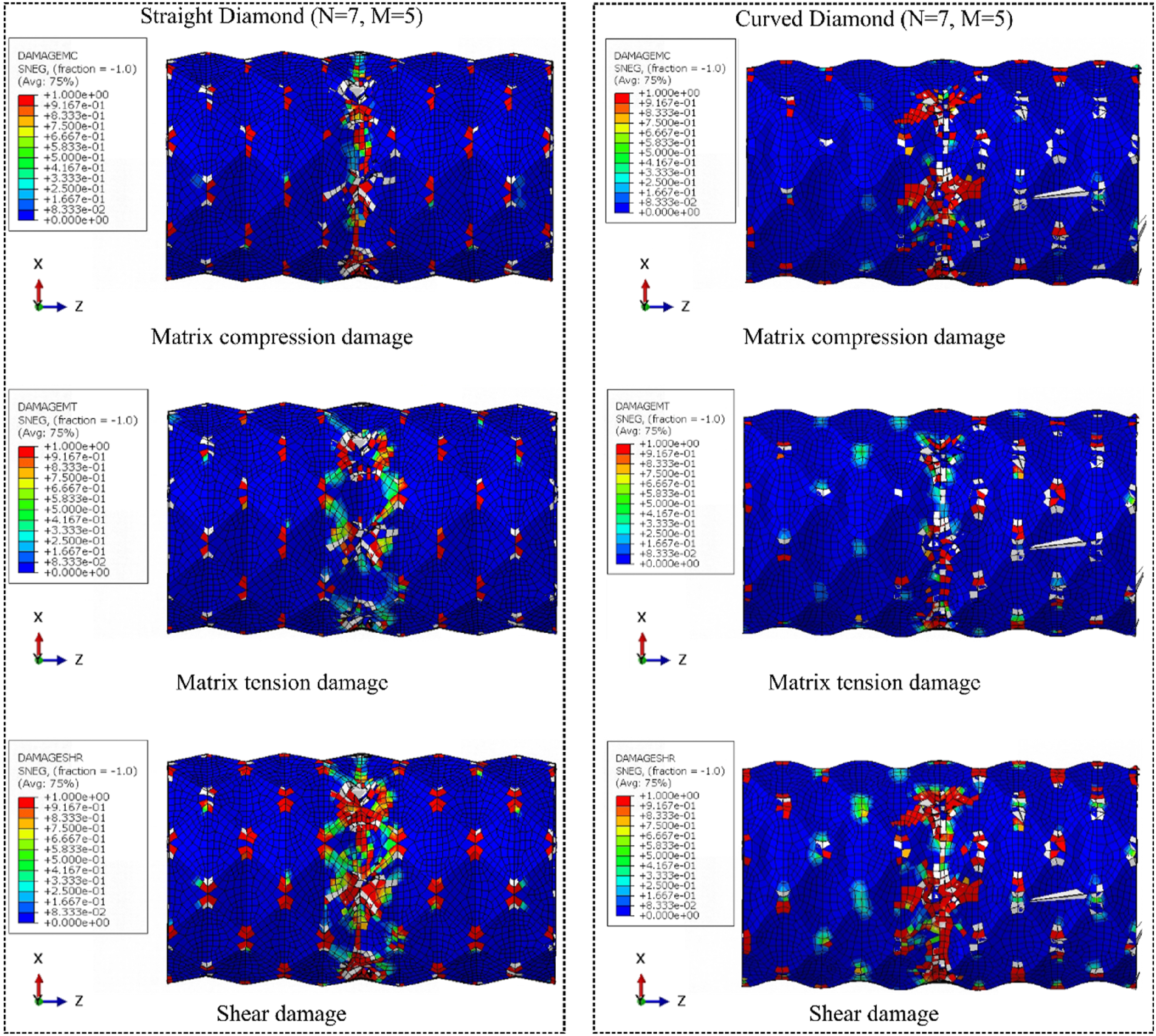
The damage mode of axial Miura configuration foldcore material under three-point bending, the figure of the damage mode is the ending state of the loading process.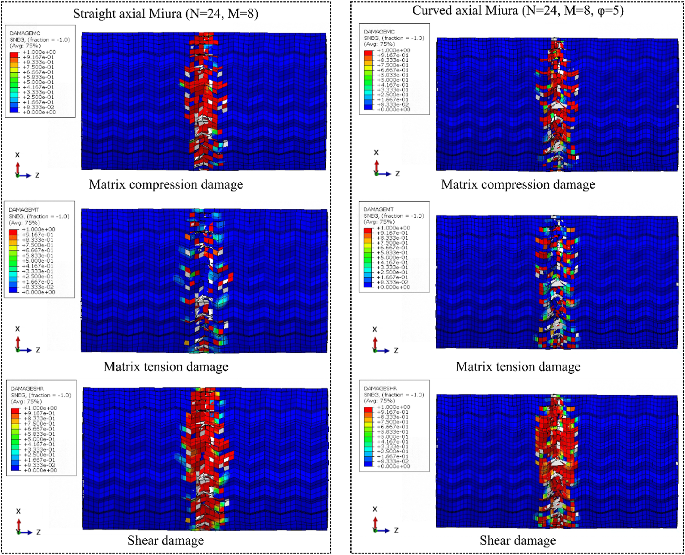
The damage mode of circumferential Miura configuration foldcore material under three-point bending, the figure of the damage mode is the ending state of the loading process.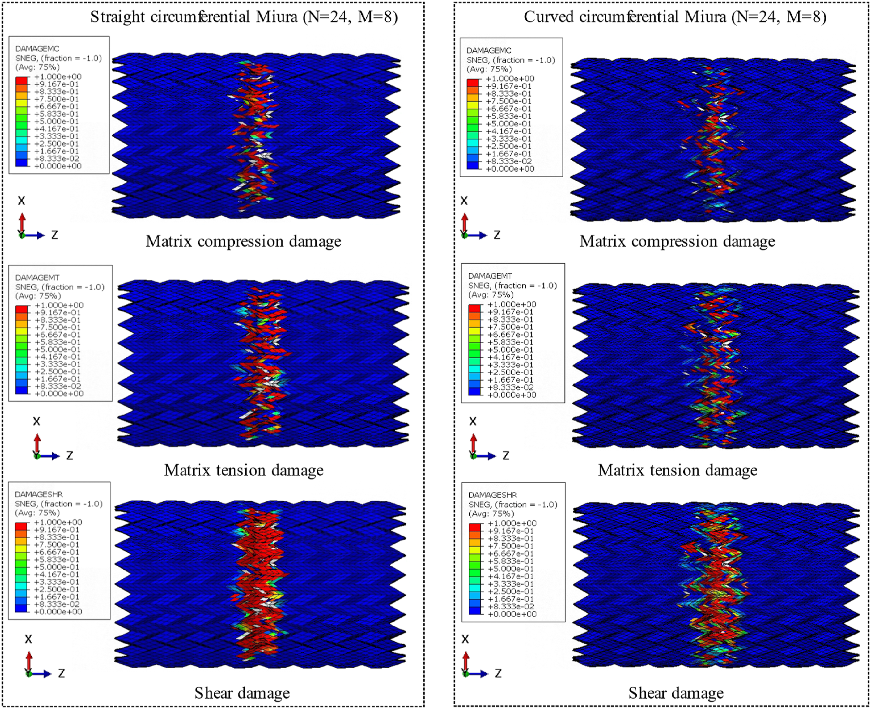
The damage mode of Kresling configuration foldcore material under three-point bending, the figure of the damage mode is the ending state of the loading process.
The damage mode of straight-diamond configuration foldcore material under plate compression, the figure of the damage mode is the ending state of the loading process.
The damage mode of curved-diamond configuration foldcore material under plate compression, the figure of the damage mode is the ending state of the loading process.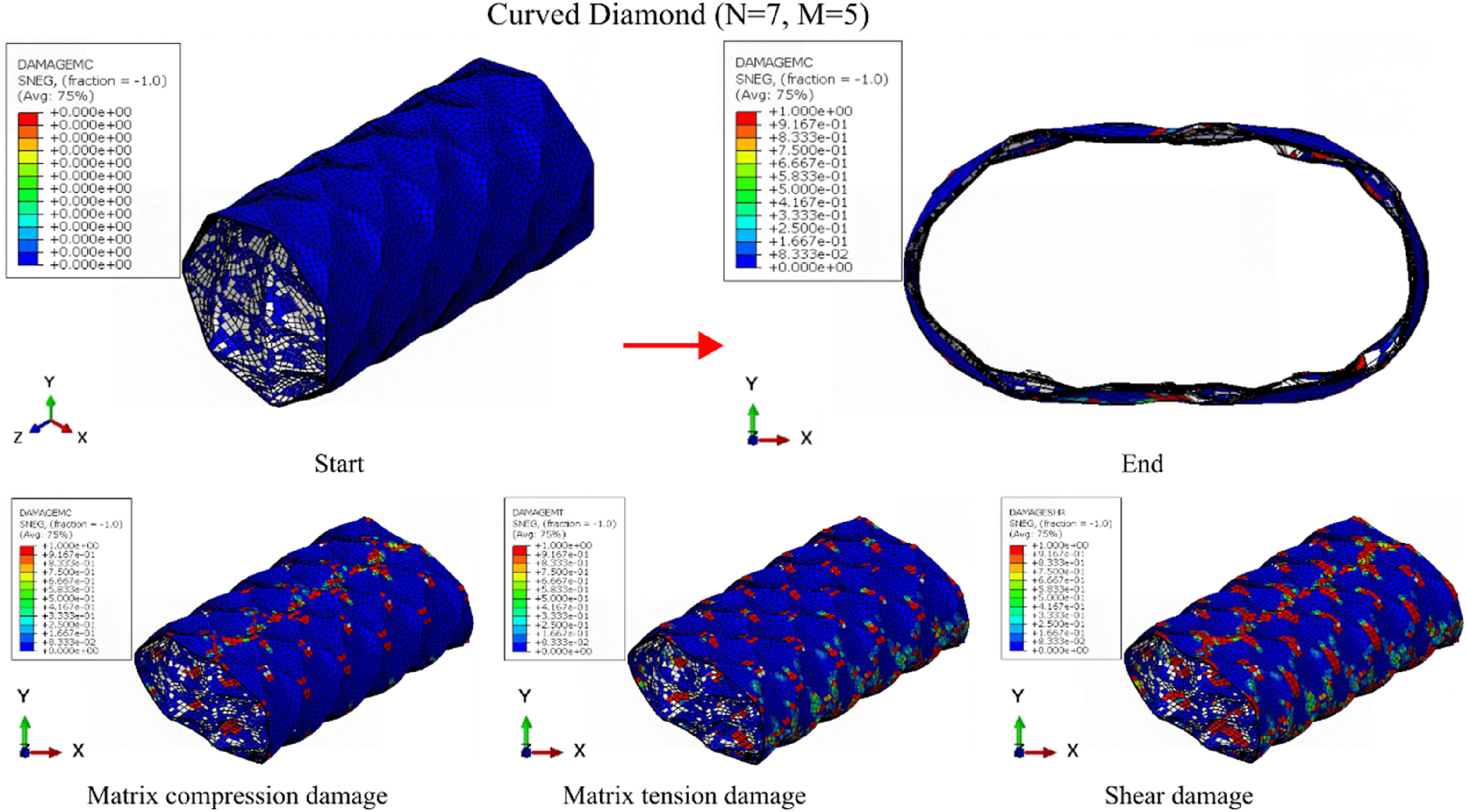
The damage mode of Straight-axial Miura configuration foldcore material under plate compression, the figure of the damage mode is the ending state of the loading process.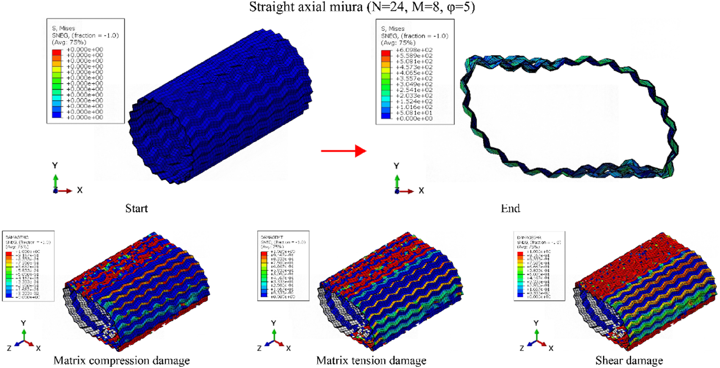
The damage mode of curved-axial Miura configuration foldcore material under plate compression, the figure of the damage mode is the ending state of the loading process.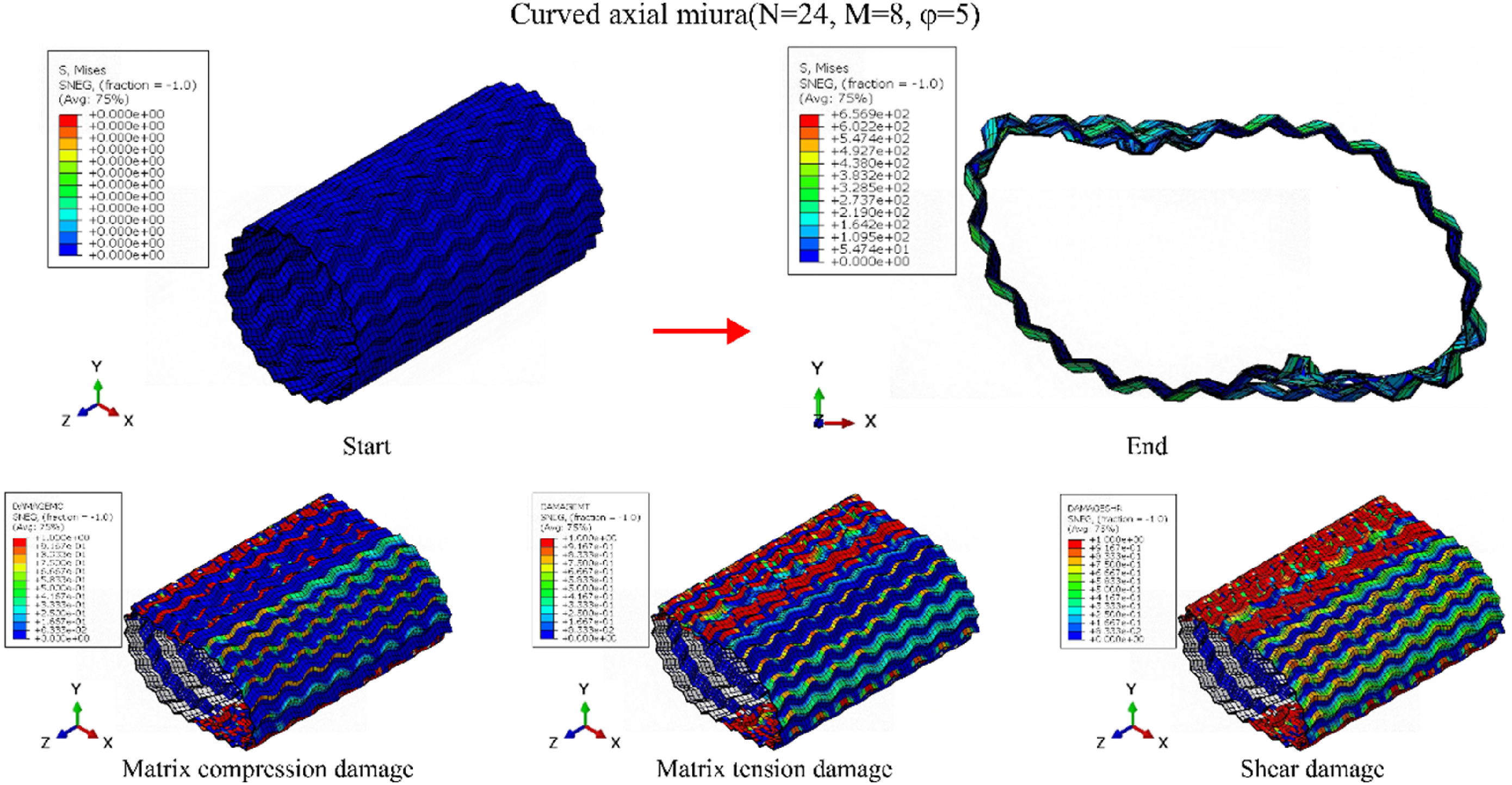
The damage mode of straight-circumferential Miura configuration foldcore material under plate compression, the figure of the damage mode is the ending state of the loading process.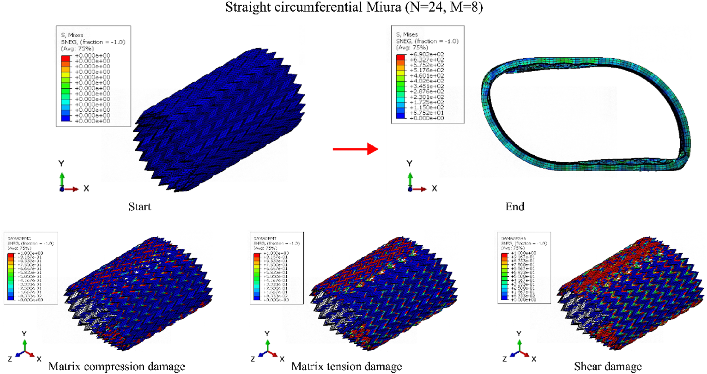
The damage mode of curved-circumferential Miura configuration foldcore material under plate compression, the figure of the damage mode is the ending state of the loading process.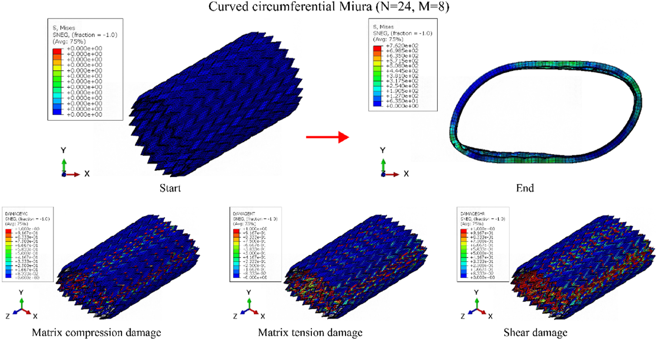
The damage mode of straight-Kresling configuration foldcore material under plate compression, the figure of the damage mode is the ending state of the loading process.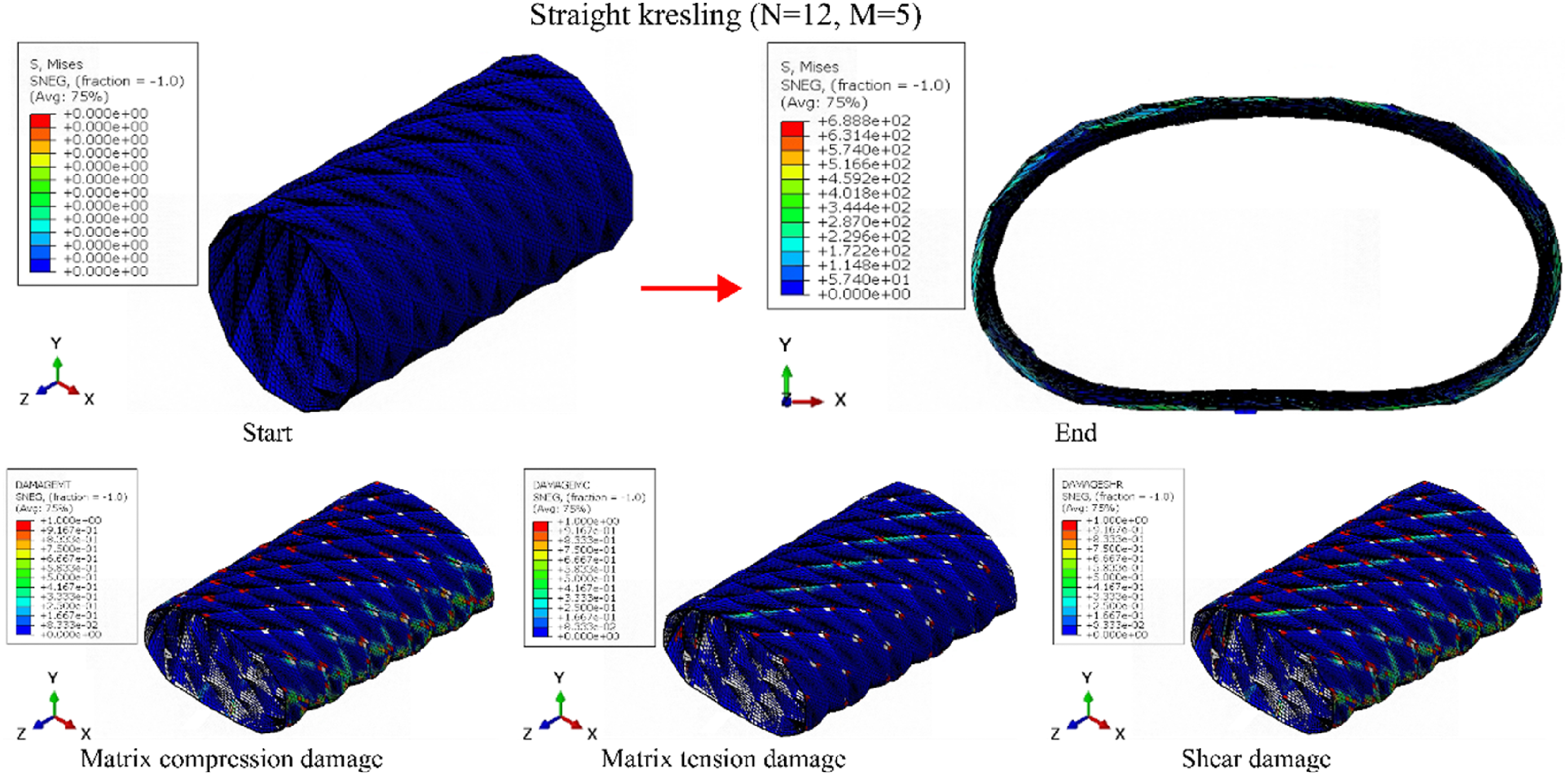
The damage mode of curved-Kresling configuration foldcore material under plate compression, the figure of the damage mode is the ending state of the loading process.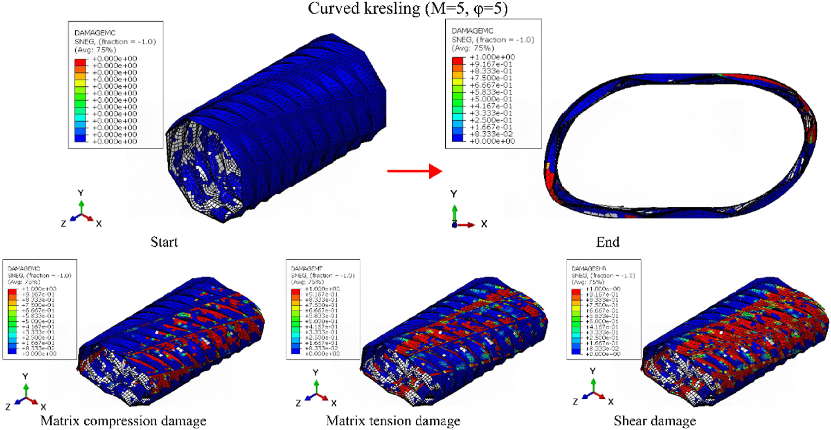
The finite element analysis results of specific energy absorption (SEA) for SAM under plate compression.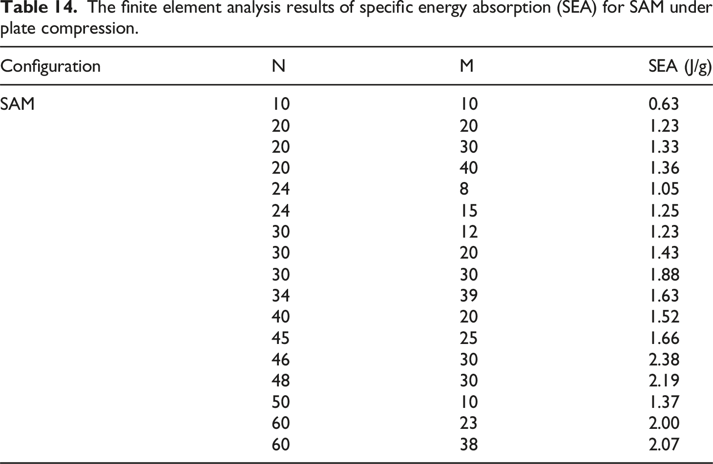
Configuration
N
M
SEA (J/g)
SAM
10
10
0.63
20
20
1.23
20
30
1.33
20
40
1.36
24
8
1.05
24
15
1.25
30
12
1.23
30
20
1.43
30
30
1.88
34
39
1.63
40
20
1.52
45
25
1.66
46
30
2.38
48
30
2.19
50
10
1.37
60
23
2.00
60
38
2.07
The finite element analysis results of specific energy absorption (SEA) for SCM under plate compression.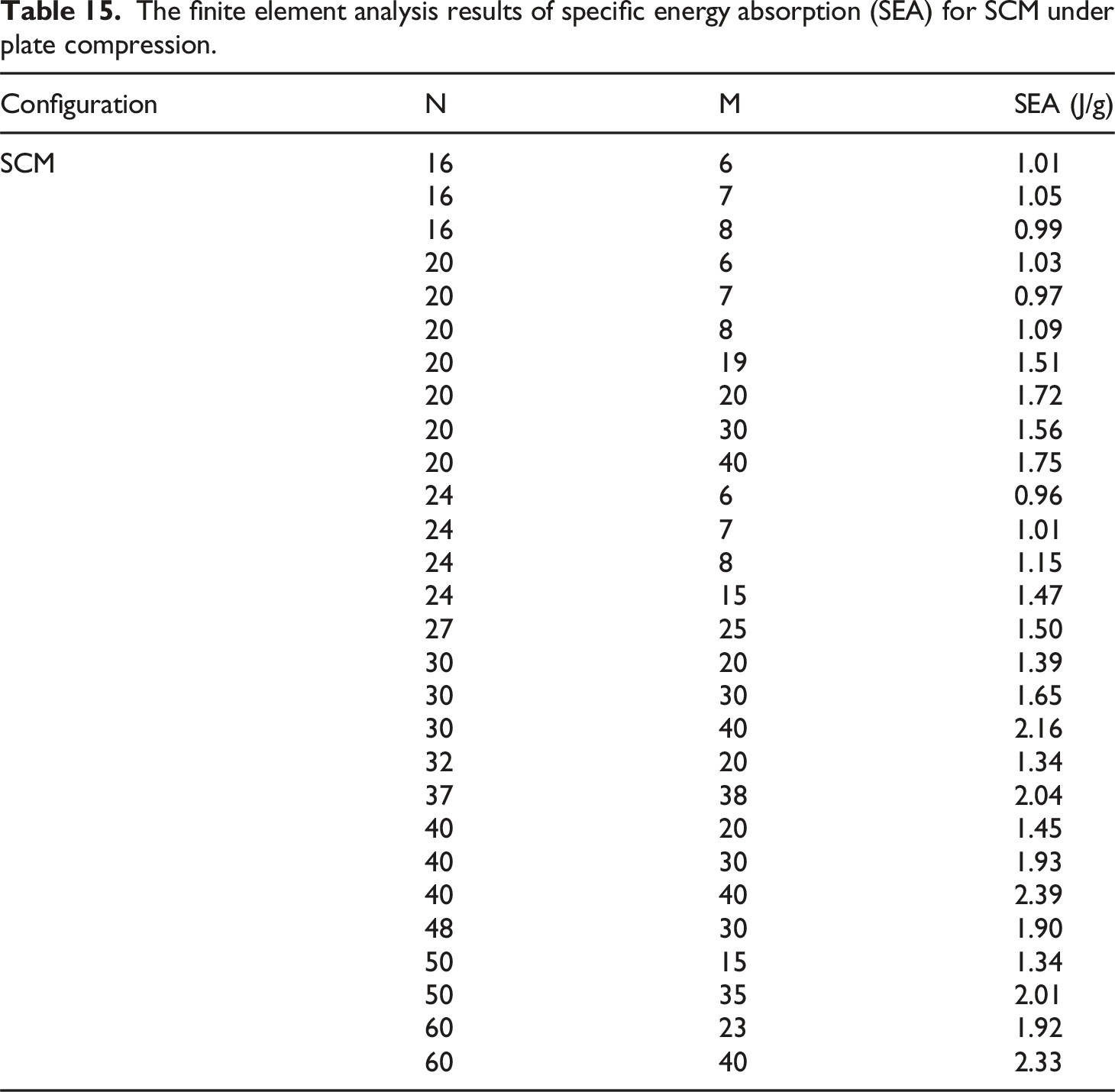
Configuration
N
M
SEA (J/g)
SCM
16
6
1.01
16
7
1.05
16
8
0.99
20
6
1.03
20
7
0.97
20
8
1.09
20
19
1.51
20
20
1.72
20
30
1.56
20
40
1.75
24
6
0.96
24
7
1.01
24
8
1.15
24
15
1.47
27
25
1.50
30
20
1.39
30
30
1.65
30
40
2.16
32
20
1.34
37
38
2.04
40
20
1.45
40
30
1.93
40
40
2.39
48
30
1.90
50
15
1.34
50
35
2.01
60
23
1.92
60
40
2.33
The fitting surface functions of SAM and SCM.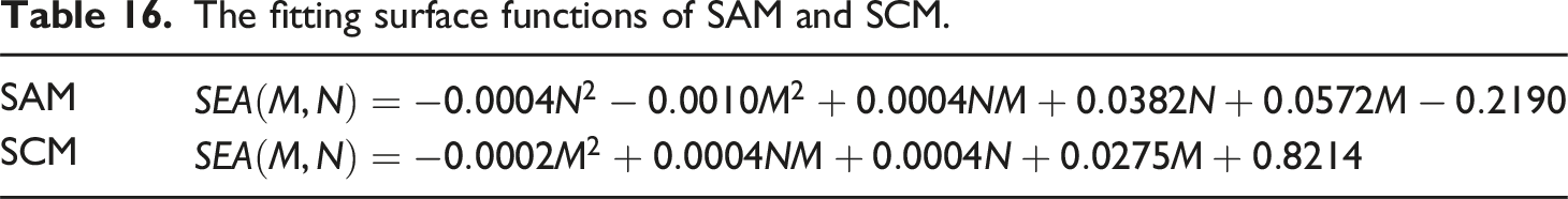
SAM
SCM