






Abstract
Recyclable, lightweight materials using advanced processing techniques are essential for the sustainable development of future wind turbine blades. Thermoplastic composite sandwich structures were developed to satisfy this need. This study presents a novel continuous approach for fabricating recoverable fully thermoplastic composite honeycomb sandwich structures. Finite element models of the honeycomb and sandwich plate, accounting for surface-to-surface contact between cells, were developed. Uniaxial compression analysis was performed on honeycombs to investigate their failure modes and energy absorption characteristics. Furthermore, the deformation mode and load-bearing capacity of thermoplastic composite honeycomb sandwich panels were examined under out-of-plane compression and shear loads. Our comprehensive finite element model, incorporating the intricate contact behavior of individual cells, demonstrated a remarkable concordance with experimental outcomes. Insightful predictions were given regarding the correlation between contact areas and load-bearing capacities.
Keywords
Introduction
Honeycomb structures are commonly used in sandwich constructions due to their lightweight nature, high strength, and efficient energy absorption.1,2 The load-carrying capacity of these structures, influenced mainly by their material and geometry, can be assessed through theoretical, numerical, and experimental methods. Recent research indicates a growing preference for all-carbon and mixed-material (composite panels with metallic cores) honeycomb sandwich structures due to their superior mechanical properties.3,4 However, this trend also raises recycling concerns, significantly increasing the use of recyclable thermoplastic materials in engineering, especially in the wind power sector, where maximizing environmental benefits is essential. 5 Thermoplastic composite sandwich panels offer unique advantages, including their recyclability, elastic-plastic properties, low density, high damage tolerance, and cost-effectiveness, 6 making them perfect for wind turbine blade materials. 7
Extensive research has focused on investigating the mechanical properties of honeycomb structures, including those made from thermoplastic materials. The term “honeycomb” encompasses diverse structures formed by periodically arranged holes within a plane, extending beyond the familiar hexagonal honeycombs. 8 These structures exhibit various core geometries, with common shapes including circular, square, hexagonal, triangular, chiral, star-shaped, re-entrant, and double V-shaped designs.9,10 Notably, the choice of geometry significantly influences the mechanical behavior of honeycomb structures. 11 Many studies indicate that hierarchical honeycomb metastructures featuring circular holes yield significant performance enhancements compared to conventional counterparts.12–14 Taking innovation further, Korupolu et al. 15 introduced a hierarchical pattern by replacing the vertex cells of regular hexagonal honeycombs with circular ones, resulting in improved out-of-plane performance. Additionally, Song et al. 16 proposed a novel hierarchical honeycomb design methodology. By incorporating triangular, square, and circular holes at the third microstructural level, they aimed to address the limitations of traditional honeycomb structures, especially their poor energy absorption properties due to post-loading damage. Ghate et al. 17 investigated the load mitigation behavior of the sandwich panels with three honeycomb core topologies (square, circular, and hexagonal) under blast loading. Du et al. 18 delved into hierarchical thermoplastic composite honeycomb cylindrical structures, examining their quasi-static axial compressive properties. Singh et al. 19 conducted a comprehensive numerical analysis of sandwich structures, examining different face sheet materials and core designs to study deformation and failure. When using carbon-epoxy face sheets, the impactor only exhibited recoil in the case of square and hexagonal honeycomb cores. Strain energy absorption was minimum for square honeycomb core and maximum for round honeycomb core.
Recent research reveals that circular honeycomb structures outperform their hexagonal and quadrilateral counterparts in terms of ballistic performance and energy absorption.20–22 The contact problem encountered in the study of circular tube honeycombs remains a sparsely explored area of research. Hu et al. 23 observed that the differences in collapse fold length and load-bearing capacity between honeycomb blocks and cylindrical tubes were significantly more pronounced in experimental observations compared to numerical simulations. One primary reason for this discrepancy was the failure of a simulation model to accurately account for the contact area between circular tubes. Specifically, the simulation model only incorporates line contact, whereas the actual honeycomb structure has an adhesive area between the circular tubes, resulting in a stronger constraint. Through a multi-scale analysis of damage incurred during the processing of CFRP circular cell honeycomb and faces, Tian et al. 24 found that when processing CFRP circular cell honeycomb and face sheets, the bond surface has a lower fracture strength than the binder or cell wall, even though the cells are bonded face-to-face rather than line-to-line. This means that when excessive force is applied during processing, failure tends to start at the bond surface.
In this paper, the load-bearing and energy-absorbing capacities of thermoplastic sandwich structures with circular honeycomb cores consisting of polypropylene (PP) honeycomb core (PP without adding any reinforcement) and continuous glass fiber (GF) reinforced PP (PP/GF) panels are investigated. Experimental studies and simulations examined the honeycomb’s deformation mode and energy absorption capability under uniaxial compression. A numerical model was developed to establish the relationship between the failure mode of honeycomb sandwich panels and their geometrical parameters under out-of-plane compressive and shear loading. Experimental tests were conducted on the sandwich panels to determine their mechanical properties. Lastly, the paper offers a comprehensive analysis of the intricate correlation between the contact area of a cell and the mechanical attributes of the structure.
Experiments
Fabrication method
Figure 1 illustrates the creation of the thermoplastic honeycomb core using a block of extruded tubes. In the fabrication process, EVA material, which has a lower melting point than PP, is added to the outer layer of the PP tube after forming. During the subsequent heating process of the circular honeycomb, the EVA material melts and fuses the cells without the need for additional adhesive. The cores and face sheets are then locally heated, melted, and pressurized, forming the final sandwich panels. After the core is fabricated, it will be stacked with the PP/GF panel into a sandwich structure, and the sandwich structure core and the panel will be bonded by heating and pressurizing. The core density and tube diameter mainly influence the structure’s mechanical properties. The contact area between cells in a thermoplastic tube honeycomb often introduces errors and serves as a key focus for model refinement. Fabrication process of a thermoplastic composite honeycomb sandwich structure.
Experiments
Geometrical parameters of the specimens.

Analytical model
The honeycomb structure is shown in Figure 2. The periodic structure of the unit cells shown in Figure 2 exhibits anisotropy, resulting in different mechanical deformation mechanisms along two directions. This necessitates separate consideration of each mechanism. The main geometric parameters include the thickness of honeycomb wall tc, honeycomb thickness t, radius of circular tube R, and face sheet thickness tf. Geometric parameters of the sandwich panel.
The ultimate strength of a honeycomb core is determined by the failure mechanism of the cell wall, which is dependent on factors such as cell geometry, material properties, and the loading conditions applied. Relative density, which relates the dimensions and shape of the cells to the overall density of the structure, is the primary factor influencing the mechanical properties of honeycombs and foams.
27
The relative density of the circular honeycomb core can be determined using the following equation
28
Analytical equations for the compressive and shear stiffness and strength of the honeycomb sandwich structure.

Material characteristics used in the formulas of Table 2.

The failure mode is a key mechanical characteristic of a load-bearing structure. Once the main geometrical parameters and load-bearing configuration are defined, the failure mode becomes predictable. A failure mechanism map is used to illustrate how the structure’s geometrical parameters affect the failure mode, and it is developed based on theoretical models of the structure’s strength or ultimate load under specific loading conditions. To increase the applicability of the failure mechanism map, the structural variables are typically expressed as dimensionless parameters. Based on the theoretical models for out-of-plane compressive strength and shear strength (as presented in Table 2), we have created separate failure mechanism maps for out-of-plane compression and shear failure. As shown in Figure 3(a) and (b), failure mechanism maps were generated to analyze the primary failure mechanisms and failure mode of the honeycomb cores under compressive and shear loading conditions. Failure mechanism maps. (a) Failure mechanism map under out-of-plain compressive loading, (b) Failure mechanism map under shear loading.
The material behavior of PP thermoplastic is characterized using the Cowper-Symonds elastoplastic model, which incorporates three key parameters: elastic modulus, yield stress, and the elastoplastic stage function. To address the initial yield behavior, the Von-Mises yield criterion is applied, offering a reliable framework for analyzing the material’s response under different loading conditions. The stress deflection tensor
If equation (2) is not satisfied, the material begins to yield and enters a state of plastic deformation. The Cowper-Symonds model expresses dynamic flow stress
After material yields, the constitutive equation is as follows
35
The material parameters of PP. 35

Points showing the dependence of yield stress on plastic strain for polypropylene in the plastic stage. 35

The Abaqus/Explicit solver is used to simulate the response of the honeycomb core and the entire sandwich structure under a uniform compressive load, with the models shown in Figure 4. The core is modeled using shell elements, while the upper and lower panels are modeled as rigid shells. Accounting for the adhesion region between two adjacent cells emerging in the fabrication process, as shown in Figure 5, results in a stronger constraint than a simple line constraint. Since contact surfaces between cells are not thought of as bonding interactions in this work, these contact interfaces are simulated by a single layer. In the finite element model, cell interaction is accounted for through surface-to-surface contact with an approximate arc angle of 10° corresponding to the contact surface. The upper press plate is subjected to a enforced displacement based on the parameters in Table 6, while a fixed boundary condition is applied to the bottom support. Finite element models of the honeycomb core and the sandwich structure. (a) Uniaxial compression of the honeycomb core in L direction, (b) Uniaxial compression of the honeycomb core in W direction, (c) Uniaxial compression of the honeycomb core in T direction, (d) Out-of-plane compression of the sandwich structure, (e) Shear of the sandwich structure. Glued sections between neighboring cells in a honeycomb specimen. Enforced displacement applied on the upper press plate.


Results and discussion
Uniaxial compression of honeycombs
Figure 6 depicts the experimental setup, which involved testing the specimen in its three main directions: L, W, and T. We analyzed the stress-strain curves, deformation modes, and energy absorption of the honeycomb core in these three directions. Direction of uniaxial loading of thermoplastic honeycomb structures.
The stress-strain curves corresponding to the three directions (L, W, and T) are shown in Figure 7(a)–(c), respectively. The experimental and FEM results are in good agreement. Under uniaxial compressive load, the loading levels in the L and W directions are comparable, while the T direction shows significantly higher loading levels. In the T direction, the stiffness (slope in the linear part of the load-deflection curve) and maximum load are almost thirty times greater compared to the L and W directions. However, the load-displacement curves for L and W show smoother transitions, while the T direction exhibits a noticeable load drop after reaching its peak load. Experimental and numerical stress-strain curves. (a) L direction, (b) W direction, (c) T direction.
According to Figure 8, the gradual collapse of the cell rows from both ends characterizes the deformation mode under loading in the L direction. When the specimen is deformed in the W direction, multiple shear bands form as the cells collapse in the middle of the specimen. In the case of loading in the T direction, the deformation mode is characterized by axial collapse of the unit cell tube. Comparison of simulation and experiment concerning the folding patterns of the honeycomb core in three main directions.
The circular honeycomb cores were meshed using 4-node shell elements (S4R) with an element size of 1 mm. The two rigid plates were meshed with discrete rigid elements, and an element size of 0.2 mm and five integration points were chosen based on the thickness of the core. Neighboring cells were bonded together by sharing a common face, following a widely used circular honeycomb simulation approach.36,37 Boundary conditions were applied to the top and bottom plates, with all degrees of freedom constrained except for the loading direction of the top plate. In the simulation step, the time period was set to 1, with Nlgeom turned on and mass scaling applied. To maintain consistency and ensure comparability, all honeycomb structures were discretized using the same meshing methodology. Specifically, individual cells were discretized into 600 elements, and the entire circular honeycomb structure into 63,720 elements.
The finite element model accurately represents these deformation patterns, except for the failure mode in the T direction. As a result of loading in the T direction, the structure was damaged. This damage was not accounted for in the finite element model, leading to the failure to simulate the experiment accurately. Consequently, this resulted in a load-deformation curve that slightly exceeded the experimental results. According to Figure 9, the Specific Energy Absorption (SEA) value is highest in the T direction and slightly higher in the W direction compared to the L direction. Comparison between simulation and experiment on SEA in three directions.
Out-of-plane compression and shear of honeycomb sandwich structure
Sketches of the test fixture indicating the loading direction and the specimens to be tested are presented in Figure 10. Testing device for out-of-plane compression and shear of sandwich structure.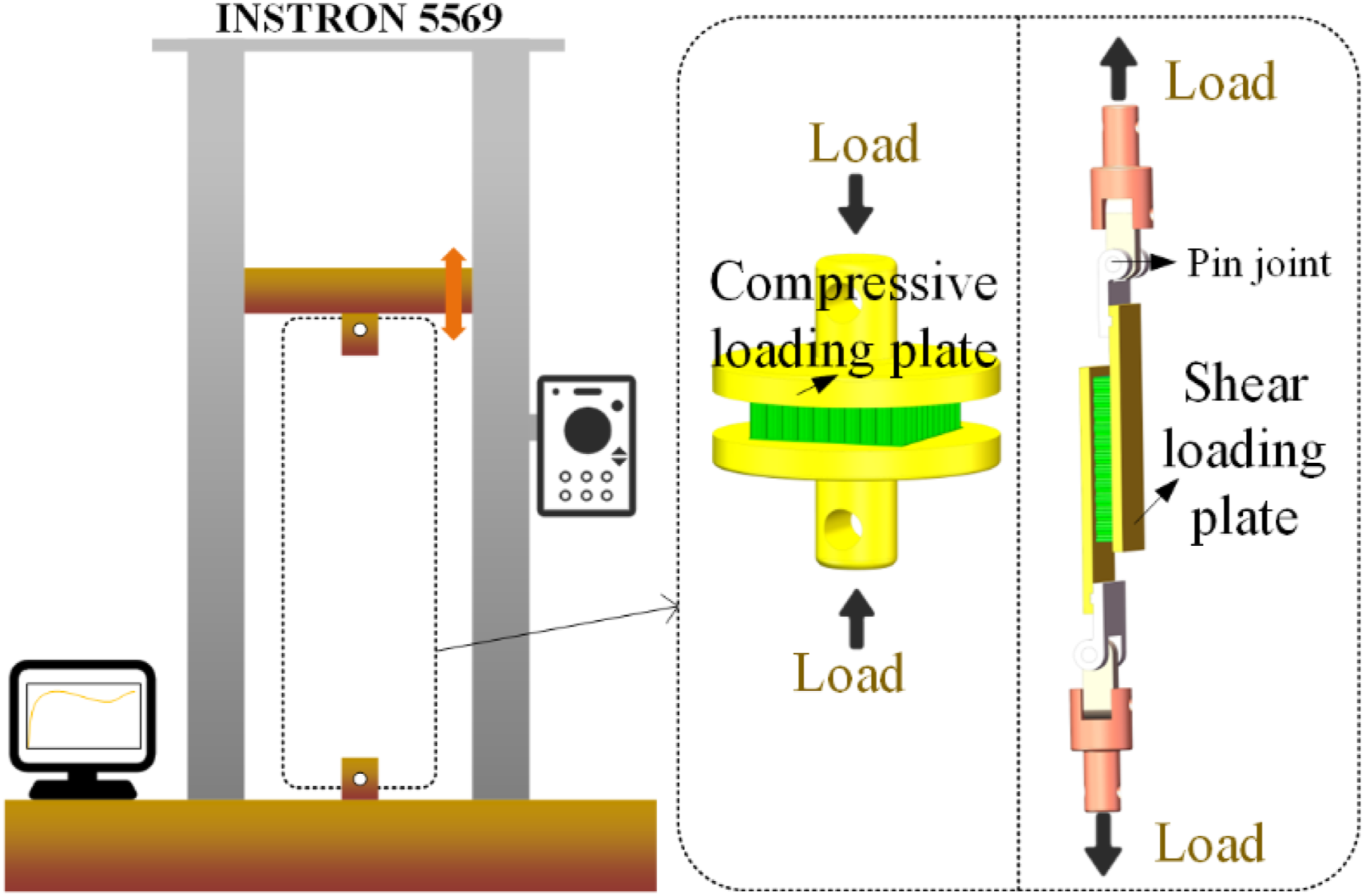
The test results in Figure 11 show that the stress-strain curves of the three specimens are highly consistent. In the out-of-plane compression test, the peak strains for the three specimens occurred at 3.837%, 3.607%, and 3.621%. The average peak stress of the three specimens was 1.6 MPa, closely matching the simulated value of 1.59 MPa, as illustrated in Figure 11(a). Similarly, as shown in Figure 11(b), the deformation patterns observed in both the experiment (Specimen 1, the red line in Figure 11(a)) and simulation align well. In both cases, plastic buckling occurs locally, gradually expanding with increasing deformation. Comparison of experimental and simulated out-of-plane compression test results. (a) Stress-strain curves for out-of-plane compressive loading, (b) Progressive failure of the thermoplastic composite honeycomb sandwich panel under compressive loading.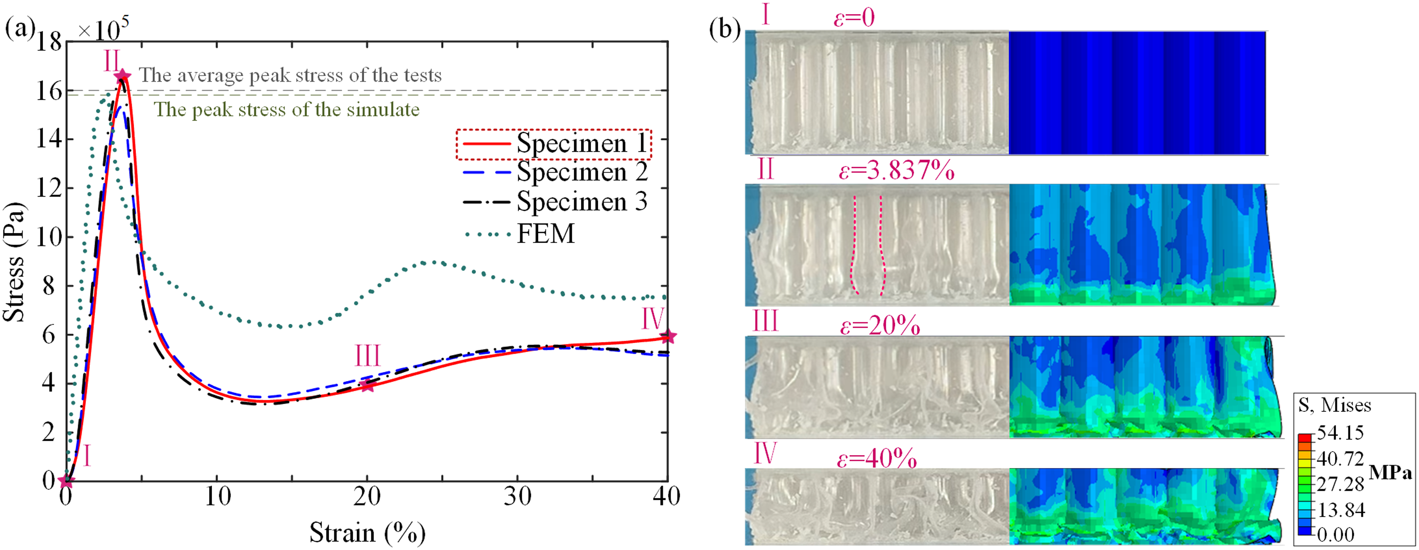
In the shear test, the peak strains for the three specimens were observed at 10.588%, 10.938%, and 10.189%. The average peak load for the specimens is 0.52 MPa, closely matching the simulated value of 0.50 MPa, as illustrated in Figure 12(a) Comparison of experimental and simulated shear test results. (a) Stress-strain curves for shear loading, (b) Progressive failure of the thermoplastic composite honeycomb sandwich panel under shear loading.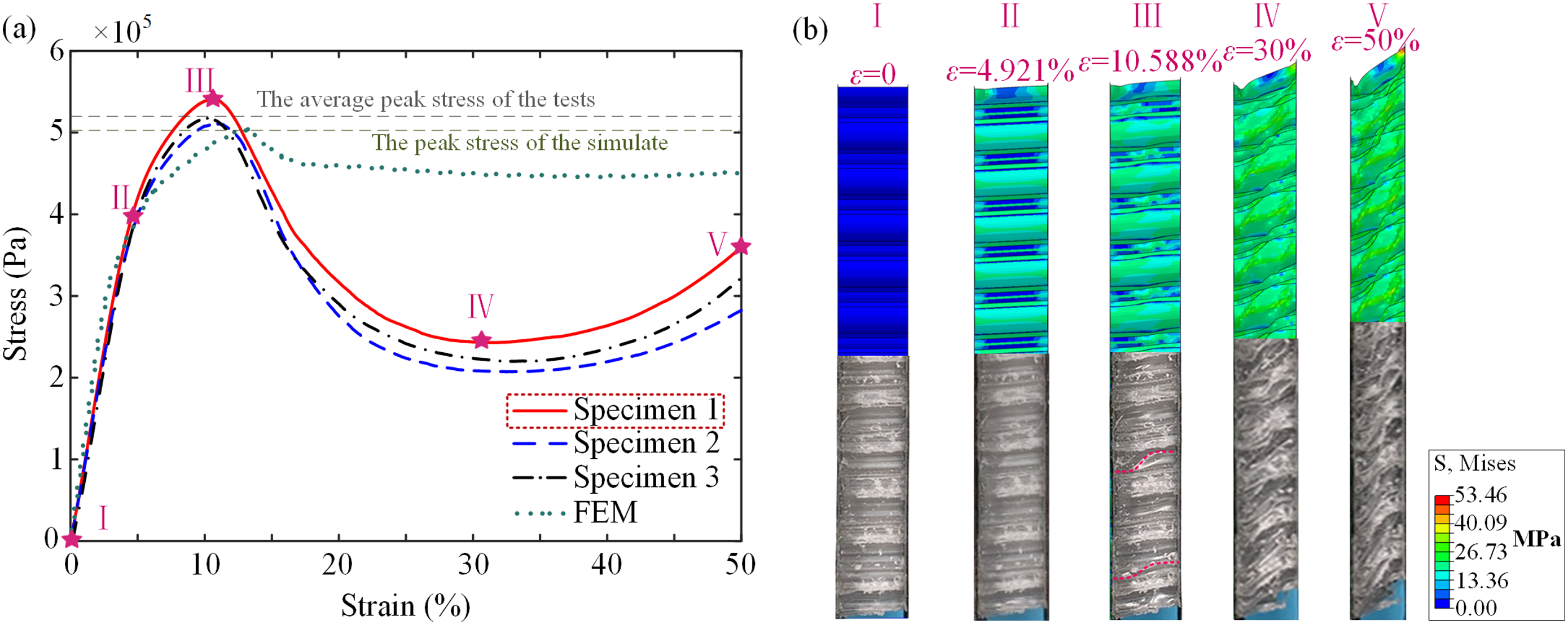
The stiffness and strength results from both the test, simulation and theory are presented in Figure 13, showing a good agreement between the three datasets. Specifically, the theoretical results are derived from the formulas provided in Table 2. Comparison of experimental, simulation and theory results. (a) Stiffness, (b) Strength.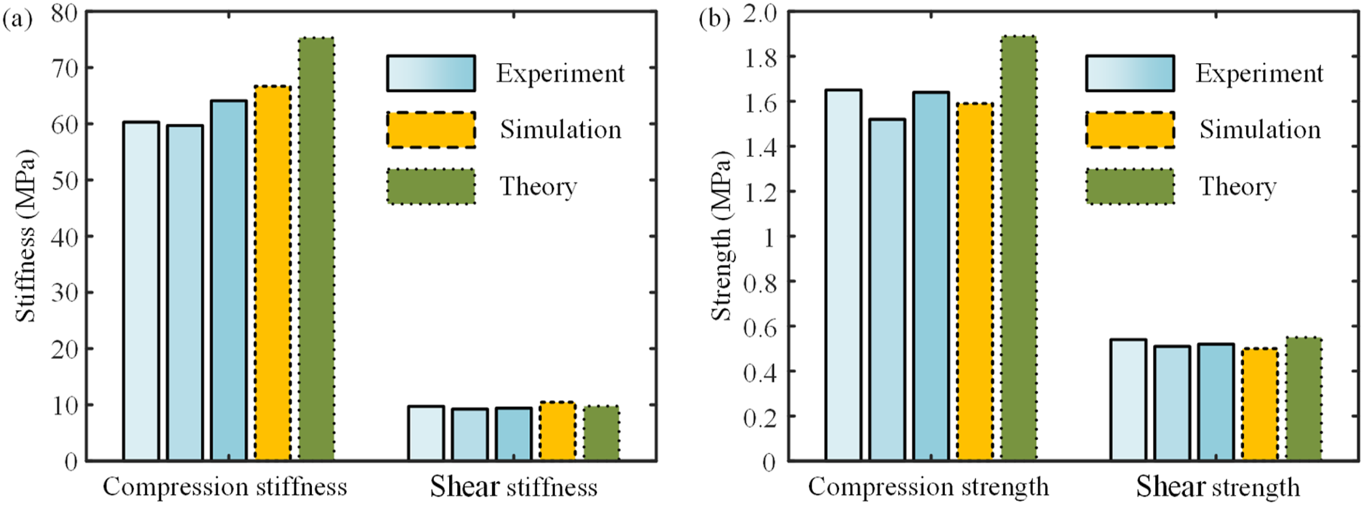
The contact relationship between core cells
Contact types corresponding to different contact areas are expressed in angles.

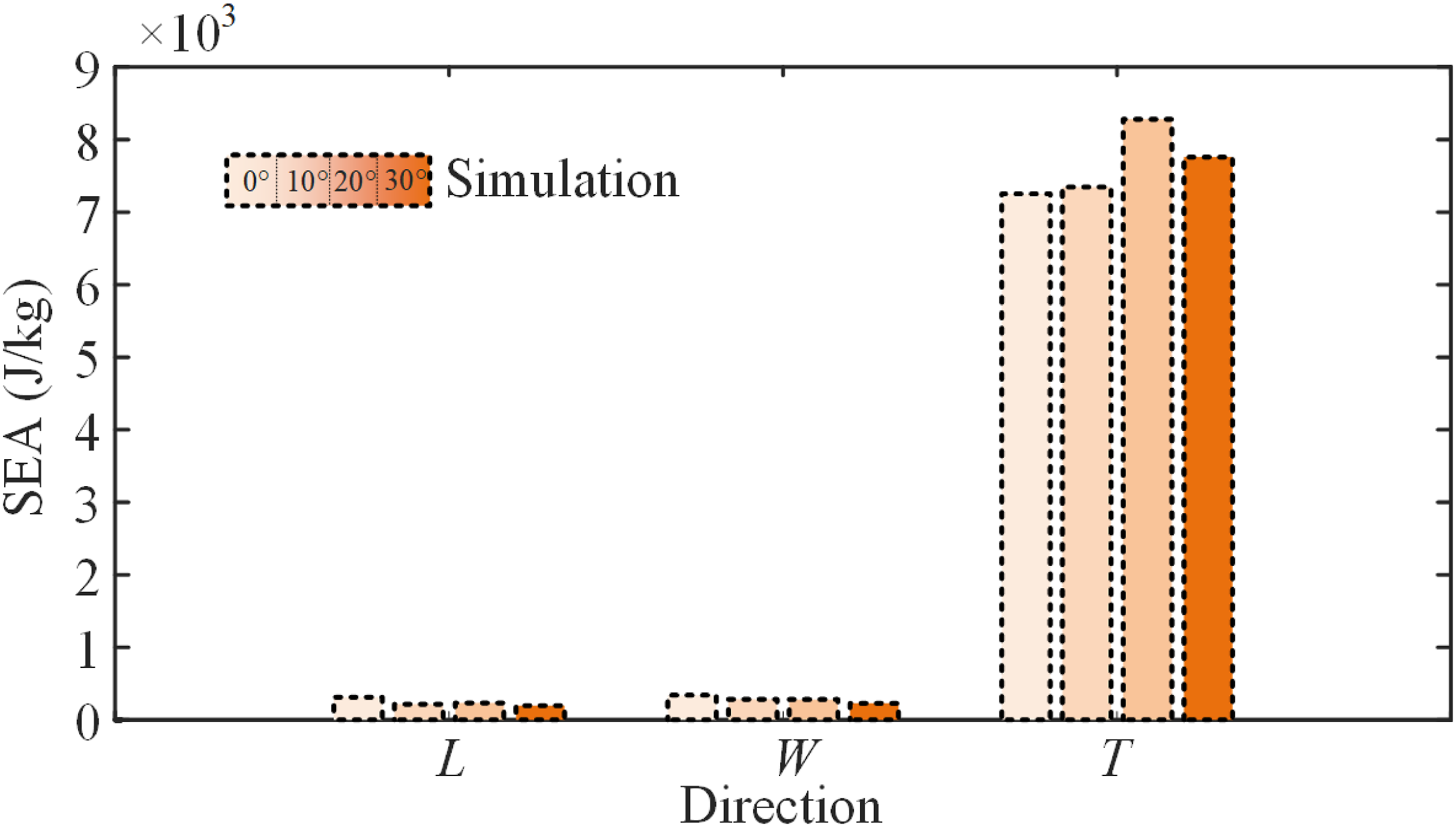
The stress-strain curves obtained for the core under uniaxial compression in three principal directions are depicted in Figure 14. Notably, there appears to be no discernible pattern between the peak or plateau load of the curve and the central angle corresponding to the contact segment. This inconsistency may arise from varying boundary conditions stemming from the specimen’s structure. Furthermore, the weak constraint imposed by the core uniaxial compression test exacerbates deformation uncertainty. Figure 15 illustrates the SEA corresponding to the three primary directions. Stress-strain curves of the core under uniaxial compression in three directions. (a) L, (b) W, (c) T. The comparison of SEA of the core obtained by simulation corresponds to different angles.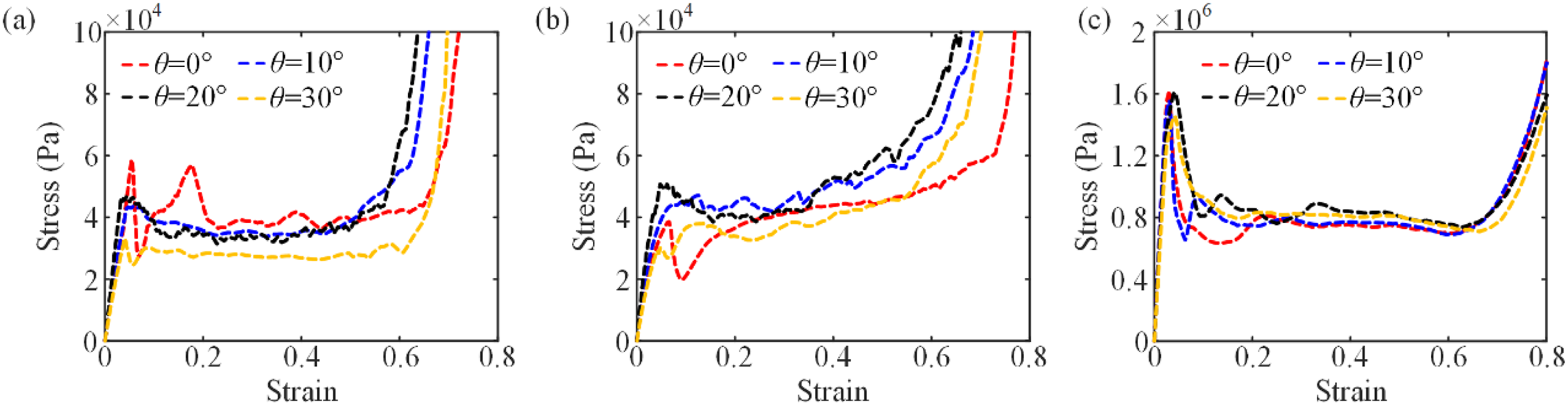
The sandwich panel offers more consistent boundary conditions than the honeycomb core alone, facilitating a comprehensive analysis of the relationship between intercellular contact area and structural load-bearing capacity. Stress-strain curves obtained using the finite element analysis of sandwich panels under out-of-plane compression and in-plane shear are depicted in Figure 16. The stress-strain curves for the sandwich panel under two loading conditions. (a) Out-of-plane compression, (b) Shear.
As the intercellular contact area increases, the peak load of the in-plane compression curve gradually decreases, accompanied by a smoother transition and increased load during the smooth segment, enhancing the structure’s energy absorption capacity. Similarly, this effect is observed in the case of shear loading.
Figure 17 demonstrates how stiffness and strength change with the contact area under the two loading conditions. As the central angle increases, both stiffness and strength decrease for out-of-plane compression and in-plane shear. Variation in stiffness and strength with central angle. (a) Stiffness for out-of-plane compression, (b) Strength for out-of-plane compression, (c) Stiffness for shear, (d) Strength for shear.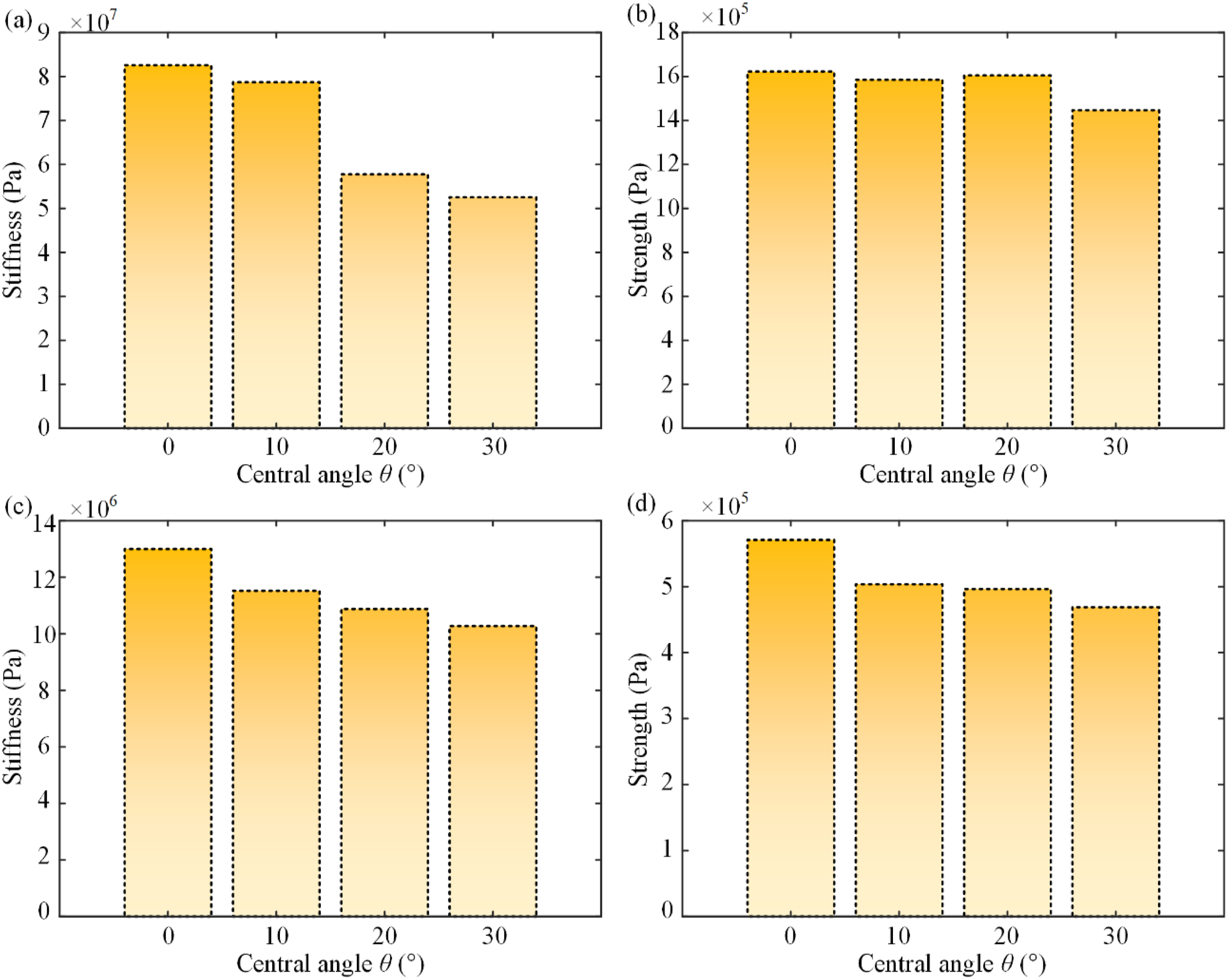
Conclusion
Thermoplastic honeycomb structures with good mechanical properties and recyclability are widely used. A novel continuous method was proposed for fabricating a fully thermoplastic composite honeycomb sandwich structure. Uniaxial compression tests were conducted on honeycomb cores to understand their failure modes and energy absorption characteristics in different directions. The results revealed effective energy absorption in both L and W directions, as the extended plateau stages indicated. However, these mechanical properties were found to be constrained by boundary conditions. A robust finite element model was developed to simulate the honeycomb core and sandwich panel, considering the contact interaction between cells. The model’s accuracy was further validated through experimental verification, demonstrating an exceptional level of agreement between the measurements and simulations. In the uniaxial compression experiments, the jump of the stress-strain curve observed for loading in the T direction was found to be less conducive to energy absorption. However, adjusting the intercellular contact area showed potential for mitigating this limitation, indicating a possible avenue for improving energy absorption performance. Experimentation involving sandwich panels, for which boundary conditions are more consistent, has shown that increasing intercellular contact area reduces compressive and shear stiffness and strength. This indicates that honeycomb structures may be better suited for bearing out-of-plane compressive load, making them applicable in lightweight structural applications such as truck bodies and modern prefab container homes. Overall, this study offers insights into the mechanical behavior and performance of thermoplastic composite honeycomb structures, emphasizing their potential for lightweight structural applications that require efficient energy absorption capabilities.
Footnotes
Declaration of conflicting interests
The author(s) declared no potential conflicts of interest with respect to the research, authorship, and/or publication of this article.
Funding
The author(s) disclosed receipt of the following financial support for the research, authorship, and/or publication of this article: The present work was supported by the National Natural Science Foundation of China under Grant No. 12061160461 and the National Key R&D Program of China (No. 2021YFB3703900).
