
Abstract
This study explores the effect of auxetic unit cell geometry and wall thickness on the energy absorption performance of sandwich composites under quasi-static and low-velocity impact (LVI) loading. Four auxetic geometries reentrant, arrowhead, starshaped, and kiteshaped were 3D-printed using ABS material and first evaluated through quasi-static compression tests with three wall thicknesses (0.44, 0.62, and 0.80 mm). Results showed that thinner-walled specimens exhibited higher initial peak forces but more brittle collapse, while thicker-walled designs provided smoother force responses. The arrowhead geometry with 0.44 mm wall thickness exhibited the highest peak crushing force (6.413 kN) while 0.44 mm starshaped geometry showed the maximum specific energy absorption (SEA) value of 6.226 J/g. Based on these results, representative auxetic cores were embedded into GFRP/epoxy sandwich panels and tested under 100 J LVI using a drop-weight setup. Among the tested configurations, the reentrant core exhibited the highest peak contact force (16.96 kN), while the arrowhead core achieved the highest absorbed energy (87.30 J) and SEA (1.89 J/g), indicating a more progressive deformation. The kiteshaped core provided the longest impact duration and smoothest deceleration profile, suggesting superior energy distribution. Finite element simulations in LS-DYNA correlated well with quasi-static compression experimental results, capturing the deformation mechanisms and validating the structural response. The findings highlight the critical role of unit cell topology and wall thickness in tailoring the impact performance of auxetic core sandwich structures for lightweight and energy-absorbing applications.
Keywords
Introduction
Sandwich composite structures are widely used in aerospace, automotive, and defense industries due to their high specific strength, impact resistance and flexibility in design options.1–6 However, under low-velocity impact loading, they are susceptible to various damage mechanisms such as surface indentation, delamination, and core crushing, which can compromise their structural integrity7–9 Lattice structures have different application areas due to their strength to weight ratio and flexibility in design. 10 As a distinctive subset of lattice structures, auxetic geometries feature engineered unit cell geometries that induce a negative Poisson’s ratio, leading to unconventional deformation mechanisms that enhance energy absorption and impact resistance.11–15 These properties make them particularly promising for the development of high-performance sandwich composites under dynamic loading conditions. Energy absorption capacity of auxetic structures can be enhanced by different methods such as filling materials into the unit cells,16,17 modifying unit cell geometry,18–23 combining different materials.24–31
Usta et al. 17 conducted an experimental and numerical study on the low-velocity impact behavior of sandwich panels with carbon/epoxy face sheets and 3D-printed PLA cores featuring various geometries, including hexagonal, reentrant, hexachiral, and arrowhead structures. In addition to the original auxetic and non-auxetic designs, certain cores were filled with polyurethane foam to investigate the effect of foam-filling on impact performance. Impact tests were carried out using a hemispherical impactor at a velocity of 2.6 m/s. Finite element simulations validated by experimental data were used for further analysis under impact energies ranging from 10 J to 76 J. The results showed that non-auxetic cores performed better at low impact energies, while auxetic structures, especially arrowhead and hexachiral designs, provided superior energy absorption and collapse behavior at higher energies. Moreover, foam-filled cores demonstrated enhanced peak force and energy absorption capacity compared to their unfilled counterparts, emphasizing the benefit of combining structural design and material filling strategies for improved impact resistance.
Zhou et al. 32 studied the quasi-static compressive behavior of three cellular structures conventional hexagonal, auxetic reentrant, and auxetic double arrowhead manufactured by 3D printing using both Nylon and carbon fiber-reinforced Nylon (Onyx). The structures were tested under in plane and axial loading. Results showed that the double arrowhead auxetic structure exhibited the highest energy absorption and specific energy absorption, especially when printed with Onyx material. The double arrowhead structure achieved 125% and 244% higher specific energy absorption than hexagonal and reentrant structures, respectively. Finite element simulations validated the experiments, and it was confirmed that material reinforcement and auxetic design both significantly enhance energy absorption efficiency and compressive strength.
Wang et al. 33 experimentally investigated the low-velocity impact behavior of innovative 3D-printed auxetic composite panels composed of glass fiber-reinforced polymer (GFRP) skins and a reentrant auxetic core made from 30 wt% glass fiber-reinforced polyamide-12 (PA12) using selective laser sintering (SLS). A total of 15 panels with varying diagonal rod radius (1.0, 1.2, and 1.4 mm) were tested under impact energies ranging from 16 to 81 J. High-speed camera observations confirmed the auxetic deformation mechanism during impact. Results showed that increasing the rod radius enhanced structural stiffness and reduced damage to the core, while increasing the damage area on the GFRP skins and the peak impact load. However, the peak impact load normalized by the core weight remained nearly constant across specimens, indicating no significant improvement in material efficiency with increasing stiffness. These findings highlight the potential of 3D-printed auxetic composites in impact mitigation applications.
This study investigates the effect of key design parameters of auxetic structures on the low velocity impact response of GFRP sandwich composites, providing insights into their potential for improved impact mitigation. First, auxetic cores have four different unit cell geometries and three different wall thickness were manufactured and subjected to quasi-static crushing experiments to understand the best design for candidate using as core material in low velocity impact test of sandwich composite specimens. Then, sandwich composite structures were manufactured and subjected to 100 J impact energy to determine the best sandwich composite with auxetic core in terms of energy absorption characteristics.
Materials and method
Design and manufacturing of auxetic structures
Figure 1 presents unit cells of samples which were printed using the FDM method on a Creality K1 Max printer. Reentrant,23,34–36 arrowhead37–41 and starshaped42–47 geometries have commonly been used in literature. The fourth geometry named kiteshaped is proposed in the context of this study. After preparing the CAD files of the samples, the slicing process was performed using Creality’s slicer software, specifically designed for its printers. In the slicing software, various printing parameters can be adjusted. One of the most critical settings is the nozzle temperature, which depends on the melting point of the filament used. Since ABS filament was selected, the nozzle temperature was set to 260°C, while the build plate temperature was maintained at 60°C. A 0.4 mm nozzle was used, and the first layer was printed with a thickness of 0.2 mm. The printing speed for the first layer was set to 50 mm/s for the edges and 105 mm/s for the infill. Isometric views of unit cells of auxetic structures in this study. (a) reentrant, (b) arrowhead, (c) starshaped, (d) kiteshaped.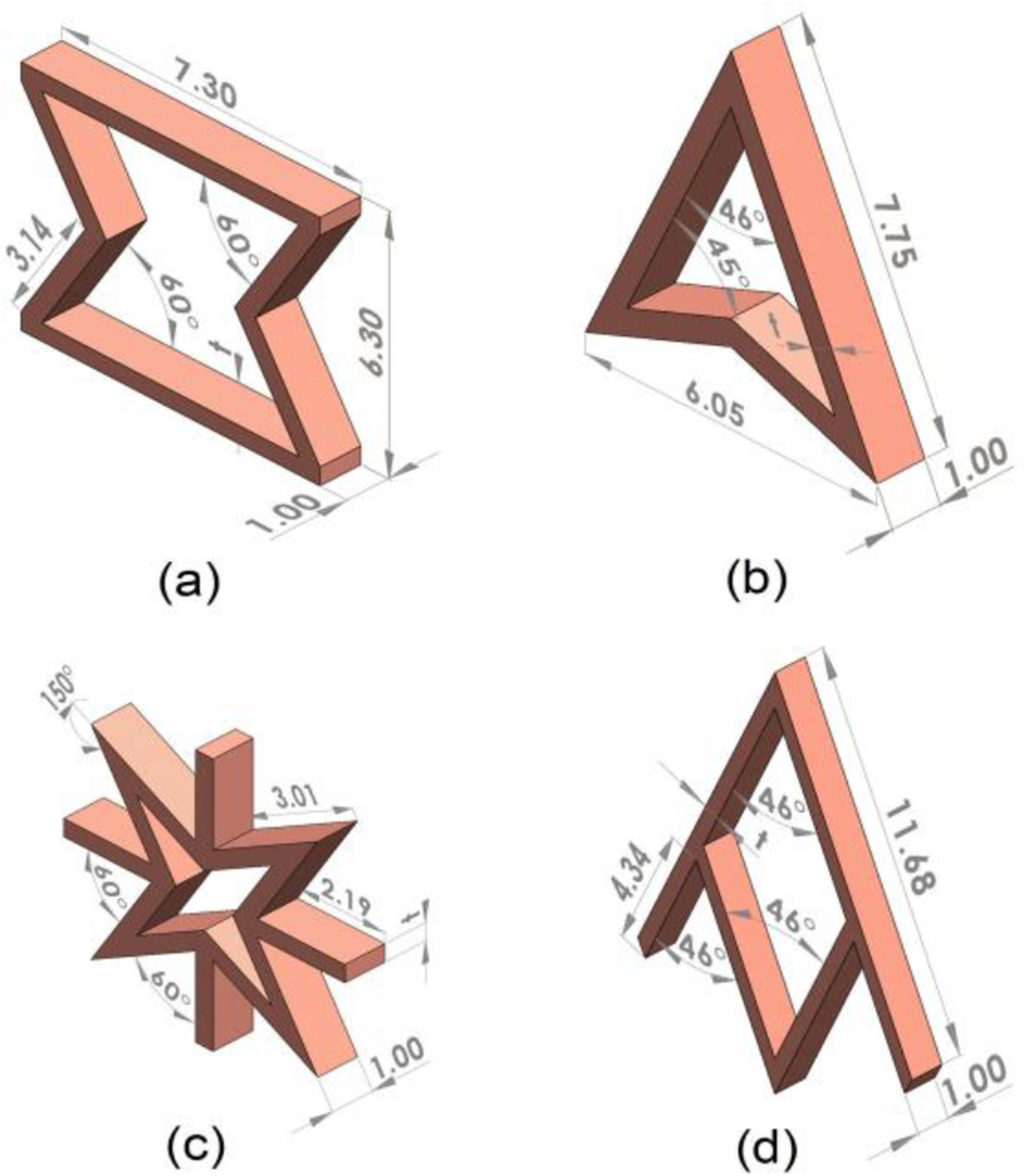
After the first layer, the layer thickness was adjusted to 0.16 mm, which is the optimal value recommended by the slicing software. The subsequent layers were printed at speeds ranging from 200 mm/s to 330 mm/s, depending on the outer wall, infill, and surface areas. The first layer was printed at a lower speed to ensure better adhesion of the filament to the build plate. Due to the geometry of the auxetic structure, attempts to print the first layer at higher speeds resulted in unsuccessful prints. The samples were manufactured with 100% infill density. Microscopic examination of the fabricated auxetic cores revealed well-defined strut boundaries, uniform wall thickness distribution, and minimal manufacturing defects across all geometries, indicating that the FDM process provided sufficient precision for reliable mechanical performance under both quasi-static and impact loading conditions.
Microscopic examination of the 3D-printed auxetic cores at 1000 μm scale can be seen in Figure 2. It is revealed that sharp strut boundaries, consistent wall thicknesses, and minimal fabrication defects across all unit cell geometries, confirming that the FDM process delivered adequate precision for subsequent mechanical testing under both quasi-static and impact loading. Microscope images of manufactured specimens. (a) arrowhead, (b) reentrant, (c) starshaped, (d) kiteshaped.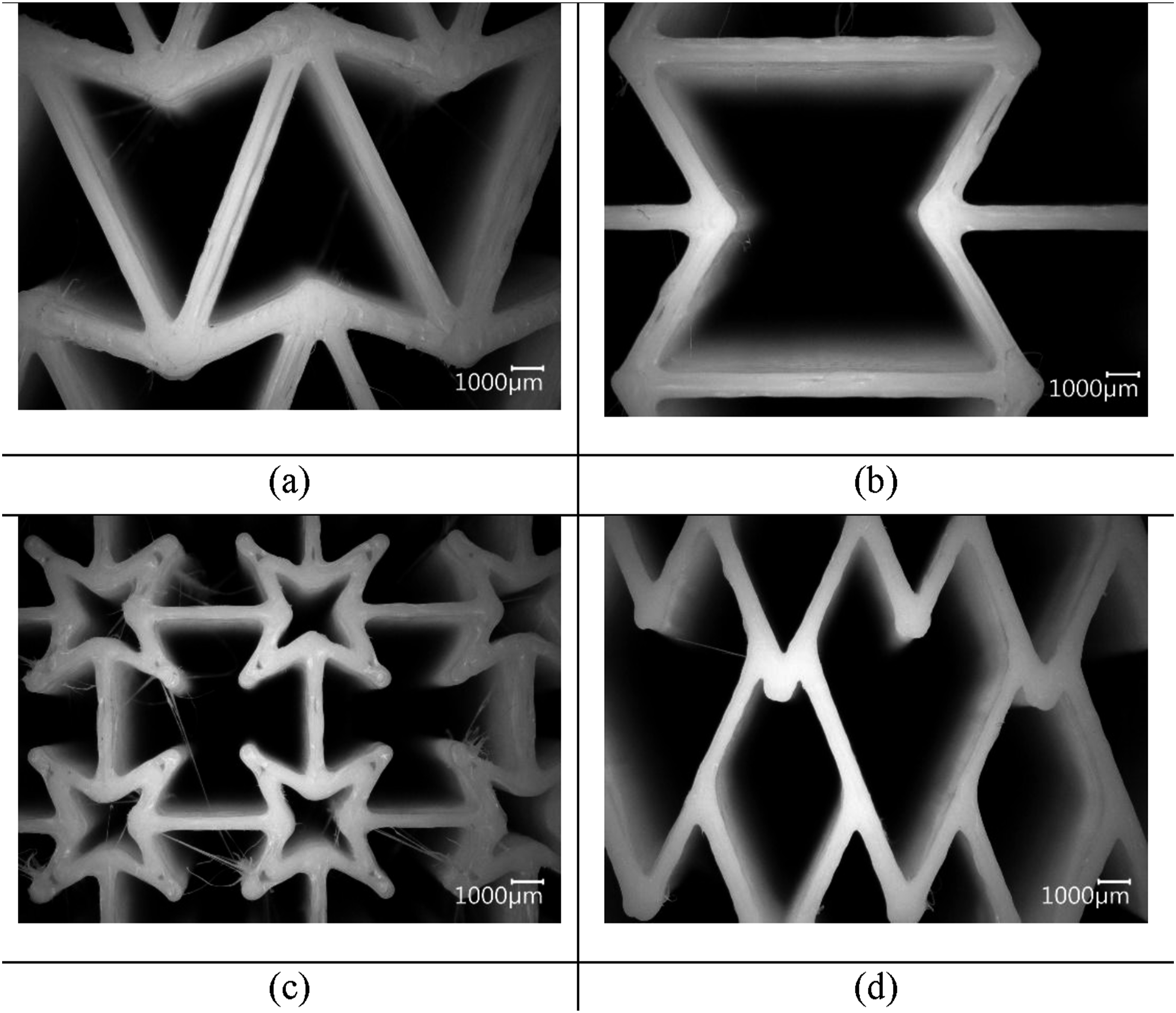
Manufacturing composite panels and sandwich structures
8-harness satin (8HS) weave S-2 glass fabric with an areal density of 302 g/m2, an inorganic 933 sizing, and SC15 epoxy resin (Applied Poleramic, Inc.) with a density of 1.05 g/cm3 were used for manufacturing composite panels, they also have different thickness.
Because of tight structure of the fabric, it is unsuitable for vacuum infusion. Due to that disadvantage the hand layup method was harnessed for production of composite plates. Warp and weft directions were aligned in the same order. Fiber volume fractions of all manufactured plates were determined by burn out test as %55 ± 1.49.
48
After the composite plate manufacturing was completed, it was cut at proper dimensions and bonded with auxetic cores by epoxy resin as in Figure 3. Auxetic cores which were put in the sandwich structure were selected according to their quasi-static test results. Reentrant unit cell core sandwich composite specimen.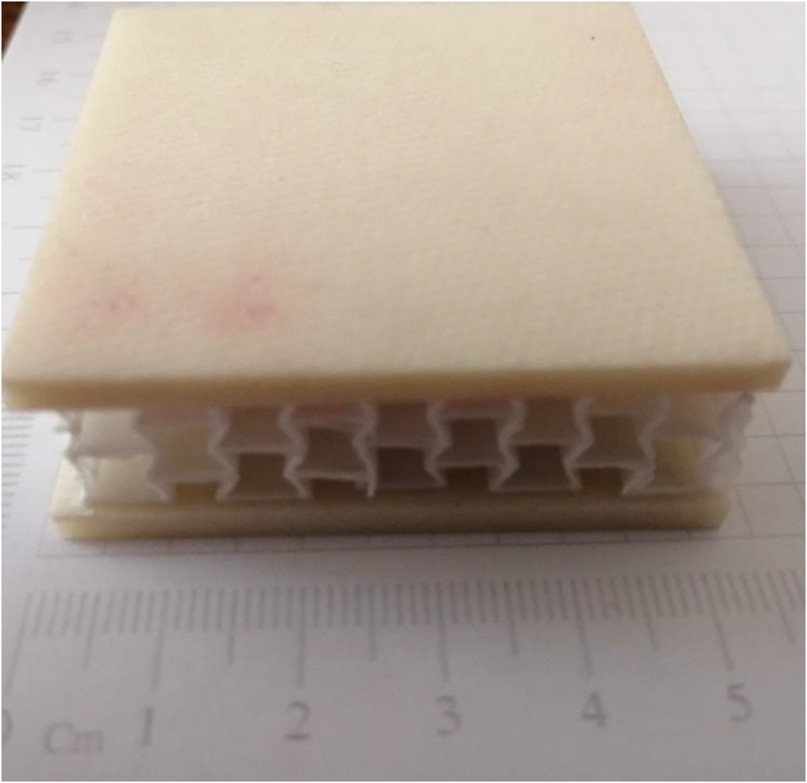
Quasi-static compression and low velocity impact experiments
Quasi-static compression tests were performed three times for each sample using a Shimadzu AGS-X universal testing machine equipped with a 100 kN load cell. A constant crosshead displacement rate of 2 mm/min was applied to all specimens in accordance with standard procedures for cellular structure compression. The tests were conducted at room temperature, and each test was recorded using a high-resolution video camera to capture real-time deformation modes, which were later used to qualitatively validate the numerical simulation results. The force–displacement data were acquired at a sampling rate of 10 Hz, and each test was repeated at least three times to ensure repeatability and statistical reliability.
Low-velocity impact (LVI) experiments were carried out using an Instron CEAST 9350 drop-weight impact testing system, capable of delivering up to 1 kJ of impact energy. In this study, a hemispherical impactor with a diameter of 20 mm and a total mass of 6.63 kg was used to generate impact energy of 100 J by adjusting the drop height accordingly. The impact energy level for the low-velocity impact (LVI) tests was selected as 100 J. This choice was based on prior experimental work in which the same composite laminates used as face sheets in the present study were tested without any core material. 48 In that earlier study, perforation occurred at an energy level of approximately 25 J. In the current study, the inclusion of auxetic cores between the top and bottom faces significantly increases the energy dissipation capacity. To ensure that perforation would occur and that the failure behavior of different core geometries could be clearly compared under critical loading, an impact energy of 100 J was selected intentionally rather than based on a standardized energy level. The system is equipped with an instrumented tup and a high-speed data acquisition unit, which records force, velocity, and displacement during impact at a sampling rate of 1 MHz. The impactor’s motion was guided by precision rails to prevent off-axis loading, and the sandwich specimens were clamped using a custom-designed fixture to simulate simply supported boundary conditions. All impact tests were performed at ambient laboratory conditions, and damage on the impacted surface was documented photographically for post-impact analysis.
Numerical simulations
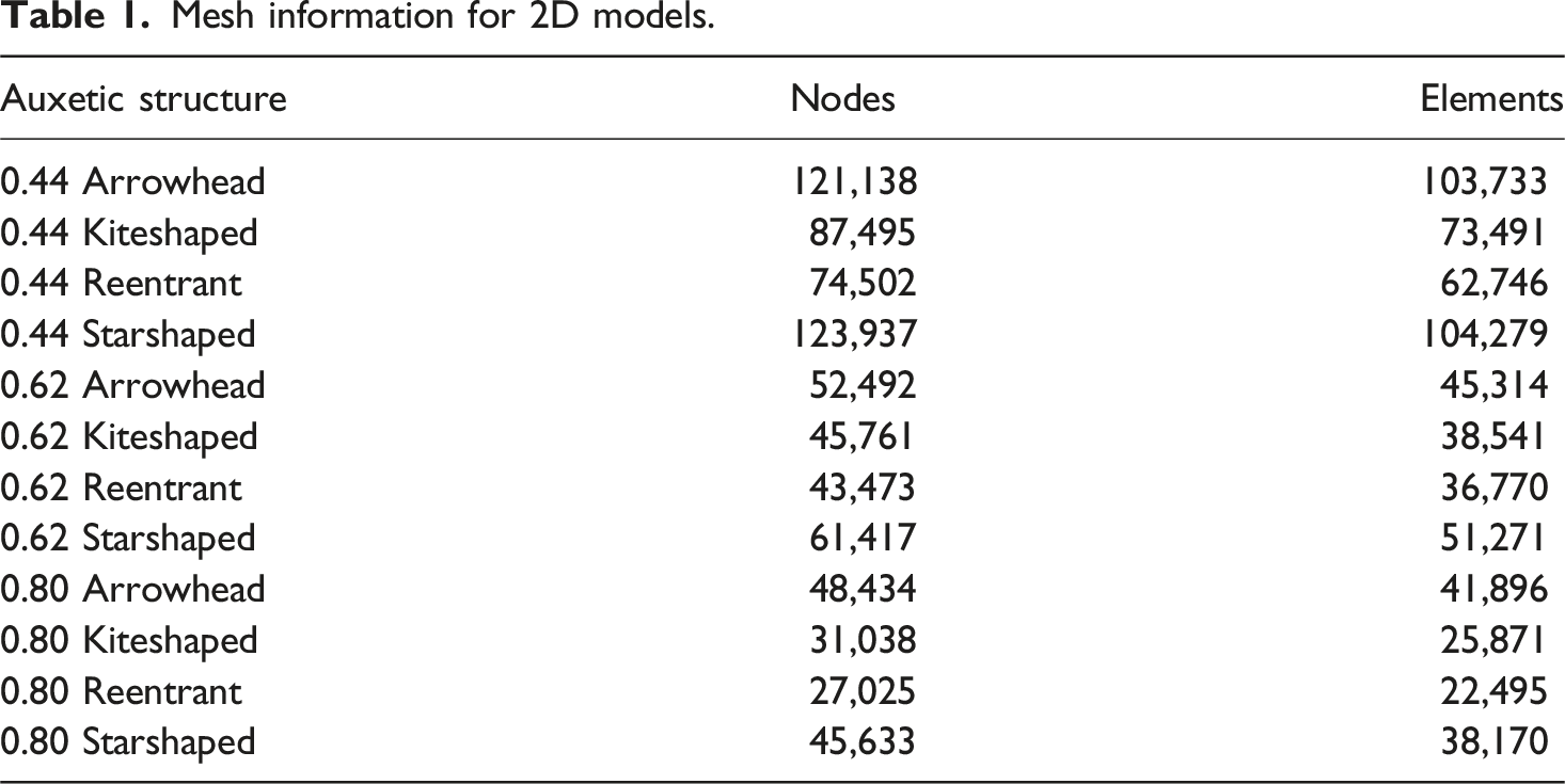
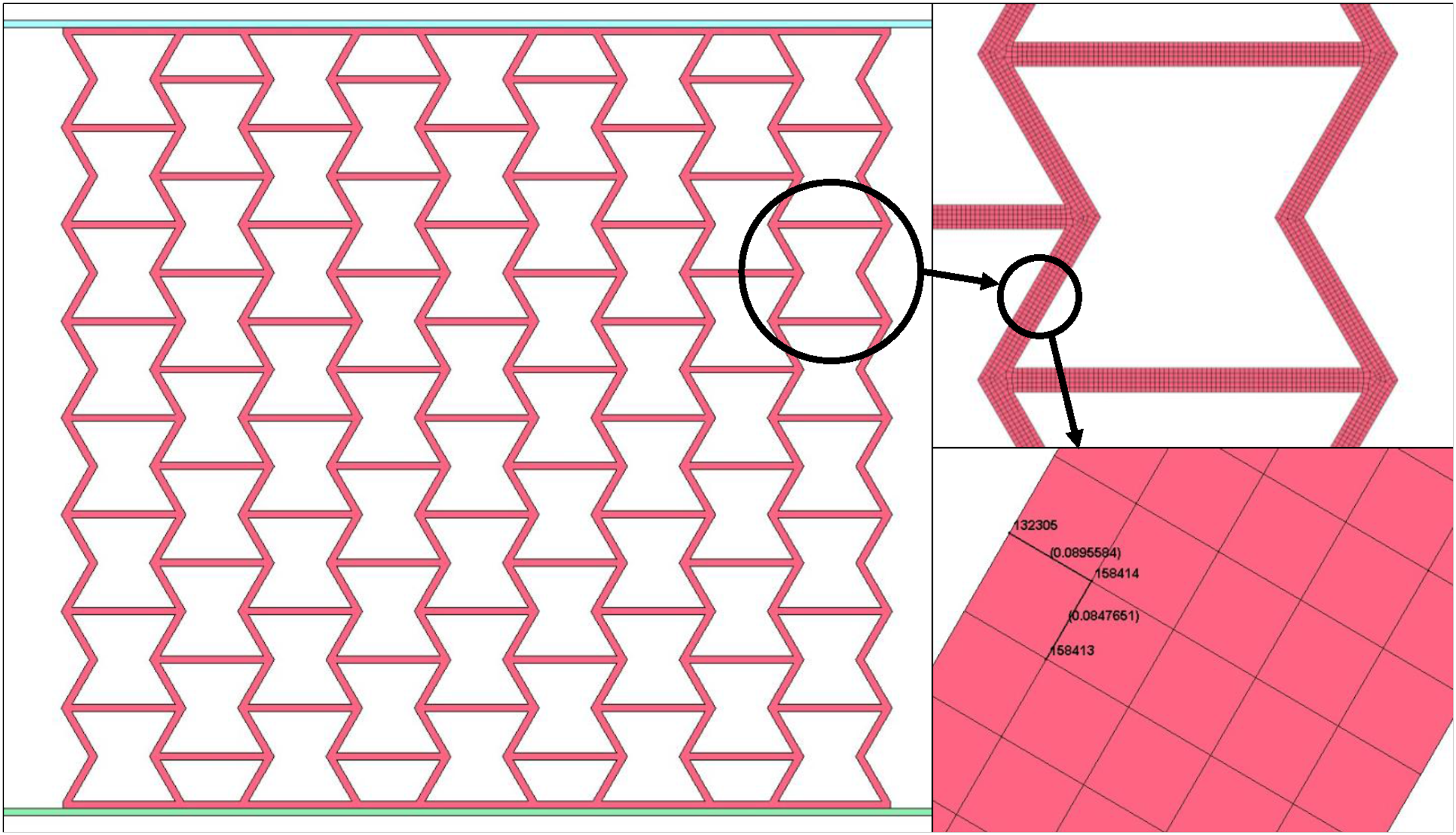
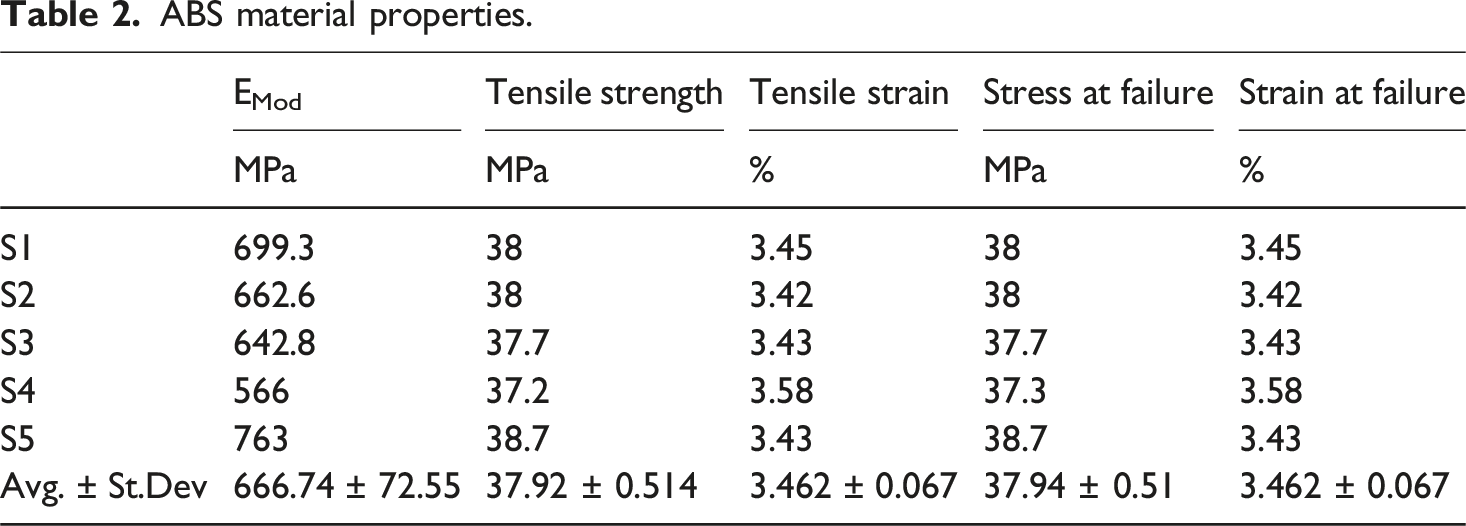
The finite element models were developed using LS-PrePost 2025 V1, and the simulations were subsequently executed using the LS-DYNA solver. Due to planer symmetry of the quasi-static compressions, 2D plane strain simulations were adopted to reduce computational cost while accurately capturing the in-plane mechanical behavior of the auxetic structures. The plain strain element formulation was selected (ELFORM = 13 *SECTION SHELL). To ensure mesh-independent results, a mesh sensitivity analysis was conducted. As illustrated in Figure 4, the simulation results converged when at least five elements were assigned through the thickness of each strut, providing a balance between computational efficiency and accuracy. The number of nodes and elements for each model is presented in Table 1. It was found that results converged when each strut has at least five elements through its thickness. The top and bottom plates were defined using the *MAT 20 RIGID material model, allowing them to impose boundary constraints without deforming. To capture the nonlinear plastic response, the auxetic structures were modeled using *MAT PIECEWISE LINEAR PLASTICITY. This material model was shown to be capable of modelling the behavior of ABS 3D-printed structures.10,49 The material parameters used in this model were based on experimental characterization: a mass density (ρ) of 1040 kg/m3, Young’s modulus (E) of 666.75 GPa, Poisson’s ratio (ν) of 0.3, yield strength (SIGY) of 37.92 MPa, and failure strain of 3.462. The plastic behavior was defined using a tabulated stress-strain curve. The load curve shown in Figure 5, which represents the stress-strain relationship, was assigned to the LCSS parameter. Results of the mesh sensitivity analysis. Mesh information for 2D models. Finite element model of the reentrant auxetic structure with 0.44 mm wall thickness.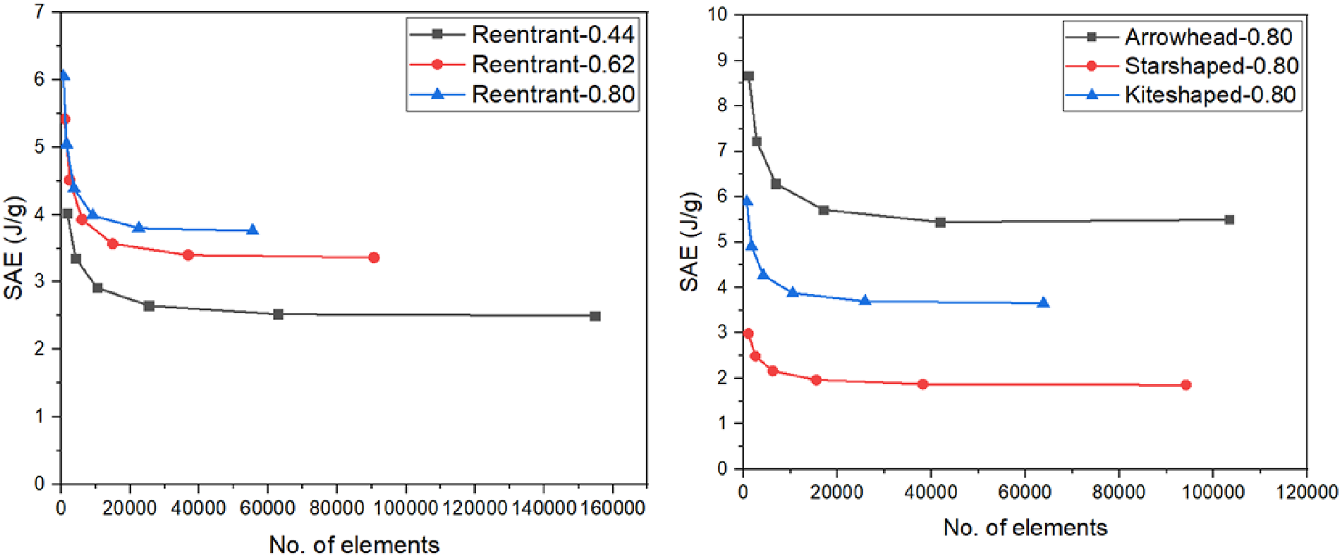
The loading condition was applied by prescribing a downward displacement on the rigid top plate using the *BOUNDARY_PRESCRIBED_MOTION_RIGID keyword. The displacement followed a time-dependent profile defined via the *DEFINE_CURVE keyword, simulating a quasi-static compression speed of 2 mm/min, in line with the experimental test protocol. The bottom plate was fully constrained by setting CON1 = CON2 = 7 in the MAT_RIGID keyword, thereby restraining all translational and rotational degrees of freedom.
Contact interactions were carefully modeled to accurately represent the interaction between structural components. The contact between the specimen and the rigid plates was defined using the keyword *CONTACT_2D_AUTOMATIC_SURFACE_TO_SURFACE, which is suitable for plane strain analyses involving contact between dissimilar bodies. To account for the potential self-contact during large deformations of the auxetic geometry, the keyword *CONTACT_2D_AUTOMATIC_SINGLE_SURFACE was employed. For both contact definition, a static friction coefficient of 0.3 was defined.
Figure 5 illustrates the finite element model of the reentrant auxetic structure with a unit cell wall thickness of 0.44 mm. The left figure shows the full model positioned between the fixed and moving plates used in the quasi-static compression simulations. A single unit cell is highlighted on the right side to demonstrate the geometric details of the reentrant pattern. The zoomed-in view in the bottom right reveals the finite element mesh at the strut level, where element dimensions were used to calculate the aspect ratio. The resulting aspect ratio was 0.946, which is within acceptable limits for element quality and ensures reliable simulation results in regions undergoing deformation.
Results and discussion
Results of quasi-static experiments
Firstly, ABS tensile tests were conducted according to ISO 527 standard to determine material properties and use them in numerical studies as material parameters. As can be seen in Figure 6 all specimens showed good agreement, and the properties were calculated as in Table 2. Stress-strain curves for ABS material used in auxetic structures. ABS material properties.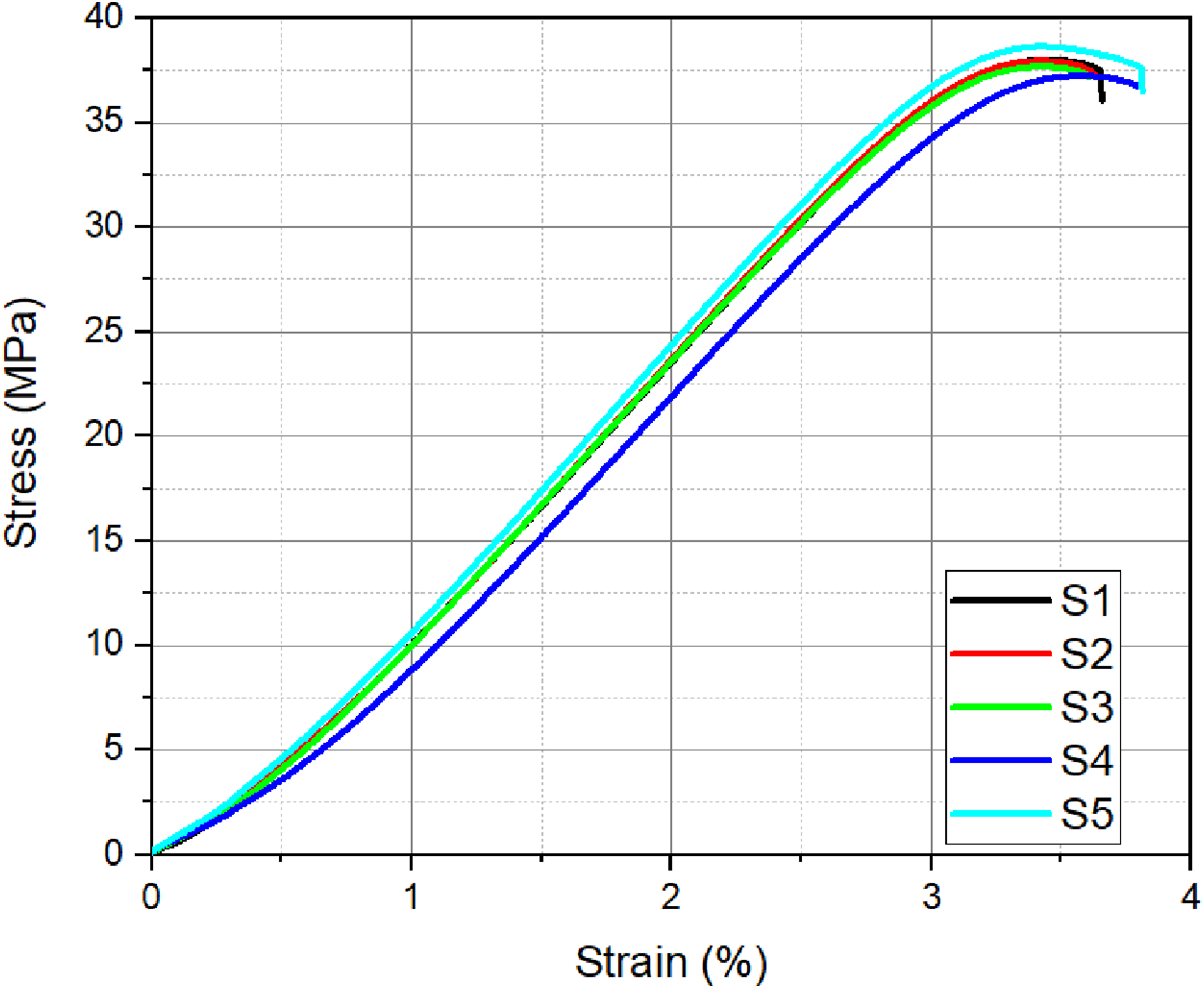
The effect of wall thickness on the quasi-static crushing response of auxetic structures was investigated for four different geometries and it is presented in Figure 7. The first 25 mm part of deflection was set to better observe the force-displacement curves reveal that reducing the wall thickness generally leads to an increase in the peak force. Effect of wall thickness of unit cell on crushing behavior of auxetic structures for different unit cell geometries. (a) reentrant, (b) arrowhead, (c) starshaped, (d) kiteshaped.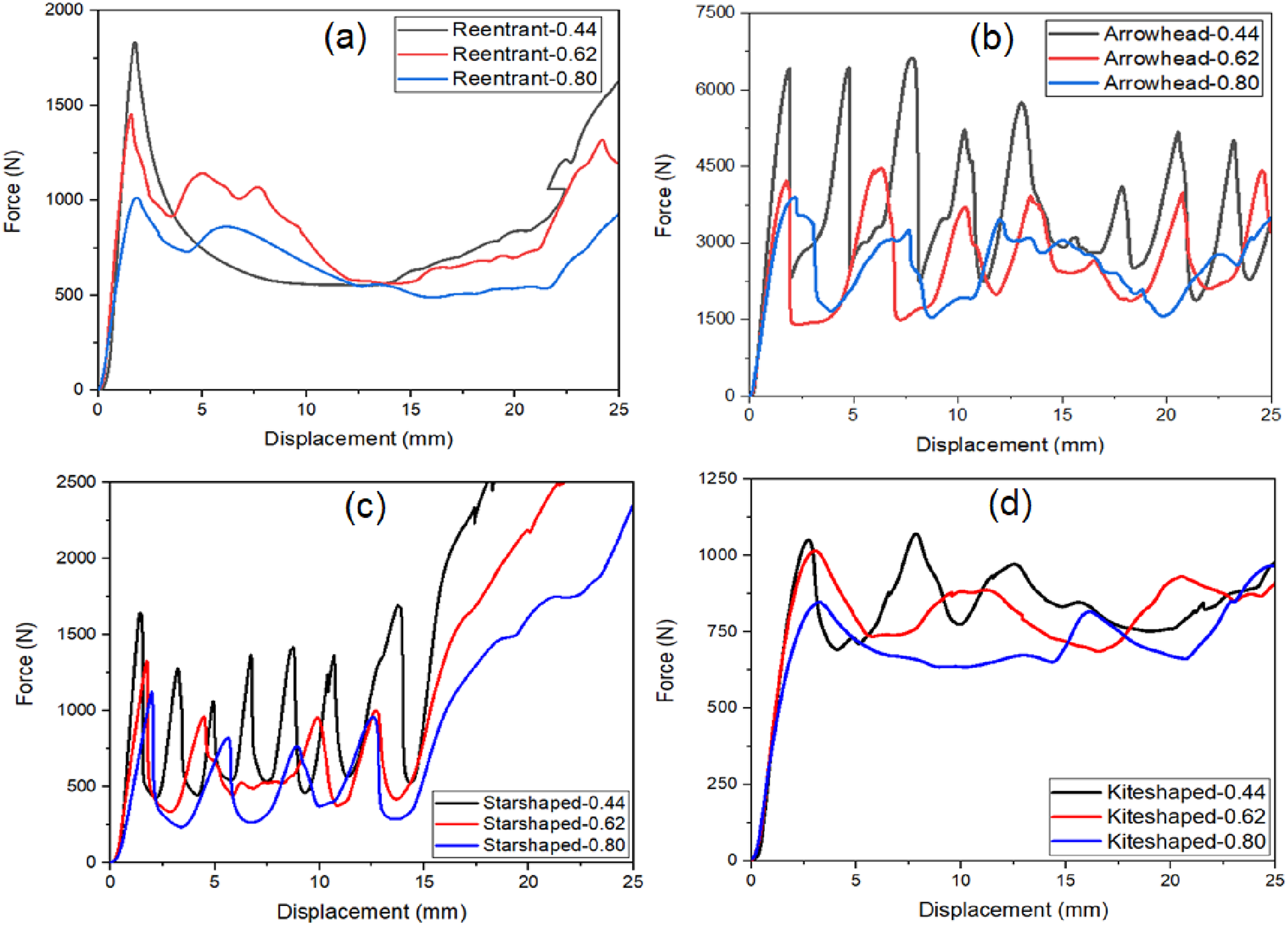
Among the tested geometries, the reentrant structure with the thinnest walls exhibited the highest peak force at the initial stage; however, as deformation progressed, thicker-walled variations maintained a more stable load-bearing capacity. The arrowhead geometry demonstrated significant force oscillations, with thinner structures reaching the highest force levels, though all variations exhibited distinct crushing phases. Similarly, the starshaped geometry displayed highly fluctuating force responses, particularly in the thinnest-walled version, where the collapse phases were more abrupt. In contrast, the thickest-walled variation of this geometry showed a more controlled deformation behavior. The kiteshaped structure operated at lower force levels compared to the others, but the influence of wall thickness remained evident, as thinner configurations produced higher initial peak forces, whereas thicker ones ensured a more consistent load-carrying profile.
These findings suggest that while thinner-walled auxetic structures can sustain higher initial loads, they tend to exhibit a more brittle collapse mechanism. In contrast, thicker-walled configurations provide a more stable force-displacement response, implying a more gradual and energy-efficient failure mode. The extent of force oscillations and progressive crushing behavior varies across geometries, being particularly pronounced in arrowhead and starshaped structures. For a more comprehensive evaluation, additional parameters such as energy absorption and specific energy absorption should be analyzed to further assess the impact resistance and deformation efficiency of these auxetic structures.
Figure 8 presents the effect of unit cell geometry on the quasi-static crushing behavior of structures for the same wall thickness. The force-displacement curves reveal significant variations in mechanical response depending on the geometric configuration. Among the tested geometries, the arrowhead structure consistently exhibited the highest peak forces, followed by the starshaped and reentrant designs, whereas the kiteshaped structure demonstrated the lowest overall force levels. Effect of unit cell geometry on crushing behavior of auxetic structures for different wall thicknesses.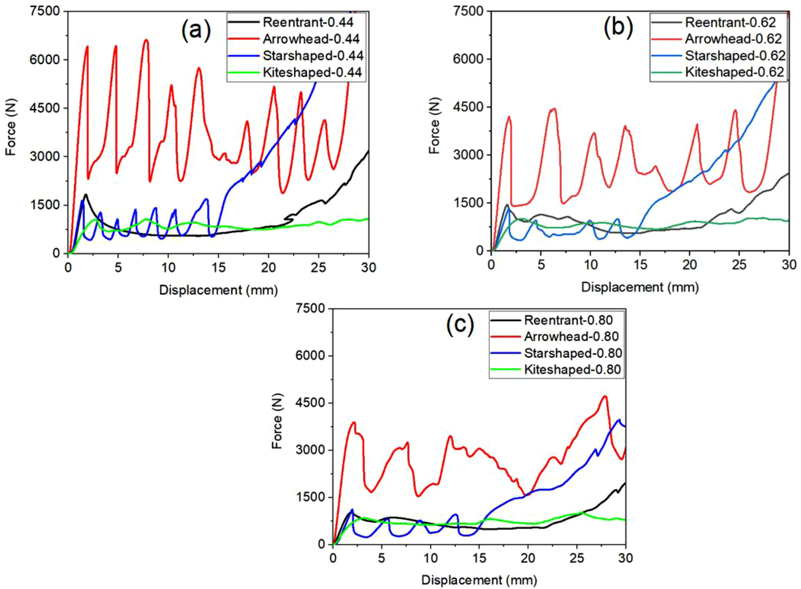
The arrowhead geometry showed pronounced force oscillations throughout the deformation process, indicating a sequential collapse mechanism that contributes to energy dissipation. The starshaped configuration displayed a similar oscillatory behavior but at a lower force range, suggesting a more gradual deformation pattern compared to the arrowhead structure. The reentrant geometry exhibited an initially high force response followed by a more stable crushing phase, with force levels remaining moderate throughout the displacement. Conversely, the kiteshaped design demonstrated a relatively smooth force-displacement trend with significantly lower peak forces, indicating a more compliant response under compressive loading.
As the wall thickness increased, all geometries exhibited a reduction in peak force magnitudes and oscillation intensity, suggesting that thicker structures undergo a more progressive crushing process. The relative rankings of the different geometries remained consistent across the tested wall thicknesses, highlighting the dominant role of structural topology in determining the load bearing and deformation characteristics of auxetic structures.
These results emphasize that the selection of auxetic geometry plays a crucial role in tuning the mechanical performance of cellular structures. The arrowhead and starshaped designs offer higher peak forces and energy dissipation through their sequential collapse mechanisms, making them suitable for applications requiring high impact resistance. In contrast, the kiteshaped structure, with its smoother force response and lower force magnitudes, may be more appropriate for applications where controlled deformation is prioritized.
To gain deeper insight into the deformation behavior and failure modes of the structures, visual analyses of the quasi-static tests were conducted as illustrated in Figures 9 and 10. Figure 9 demonstrates the progressive deformation of the 0.44 mm wall thickness specimens during impact, revealing the step-by-step collapse behavior dominated by localized buckling and gradual core compaction. This sequential view provides insight into the energy absorption mechanisms unique to each geometry. Complementarily, Figure 10 displays the final state of all tested samples, where variations in failure modes, indentation depths, and damage dispersion clearly reflect the distinct structural responses influenced by unit cell design and wall thickness. The reentrant core exhibited uniform inward folding initiated from the top layers and progressing downward, characterized by progressive cell wall buckling and densification. This controlled deformation mode is attributed to its concave geometry, which facilitates energy absorption through distributed plastic hinge formation. The arrowhead structure, on the other hand, revealed localized buckling at the mid-height of the specimen, leading to stepwise collapse. This suggests a sequential failure mechanism, with strain concentrating around the arrow tips, triggering local instability. The starshaped geometry displayed a global folding mode, in which symmetric unit cell rotations and wall bending occurred throughout the specimen height. This led to a balanced mechanical response, combining strength with deformation stability. Lastly, the kiteshaped core showed edge-initiated asymmetric folding, where lateral regions collapsed earlier than the central zone. This deformation pattern implies that stress was concentrated near the wider regions of the unit cell, resulting in mixed-mode failure involving both bending and buckling. These mechanisms, verified through both visual and numerical data, explain the differences in specific energy absorption and peak force across geometries and support the suitability of certain cores for impact-critical applications. Crushing behavior of auxetic structures under quasi-static compression loading. Deformation modes of auxetic specimens at the end of quasi-static compression test.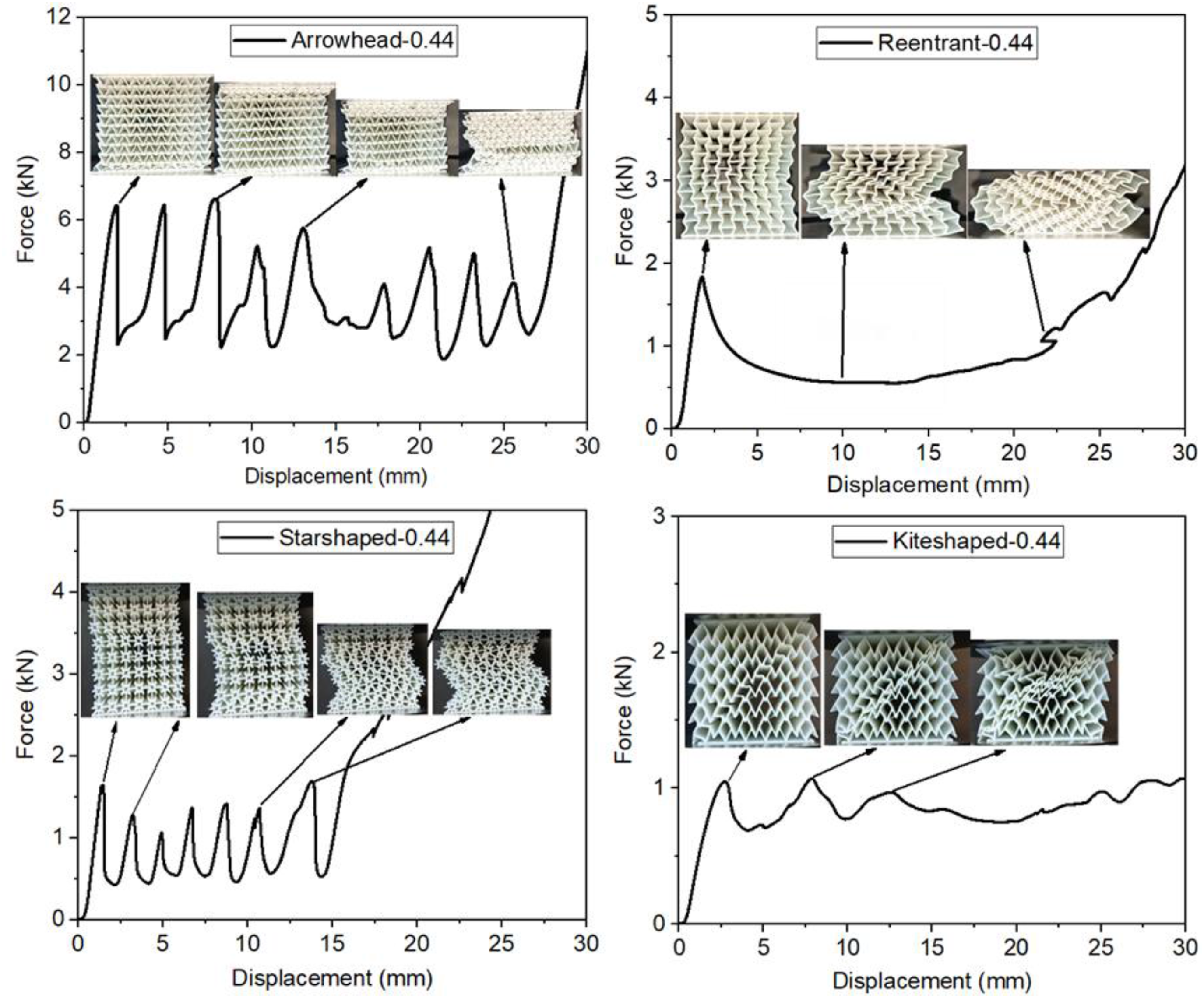
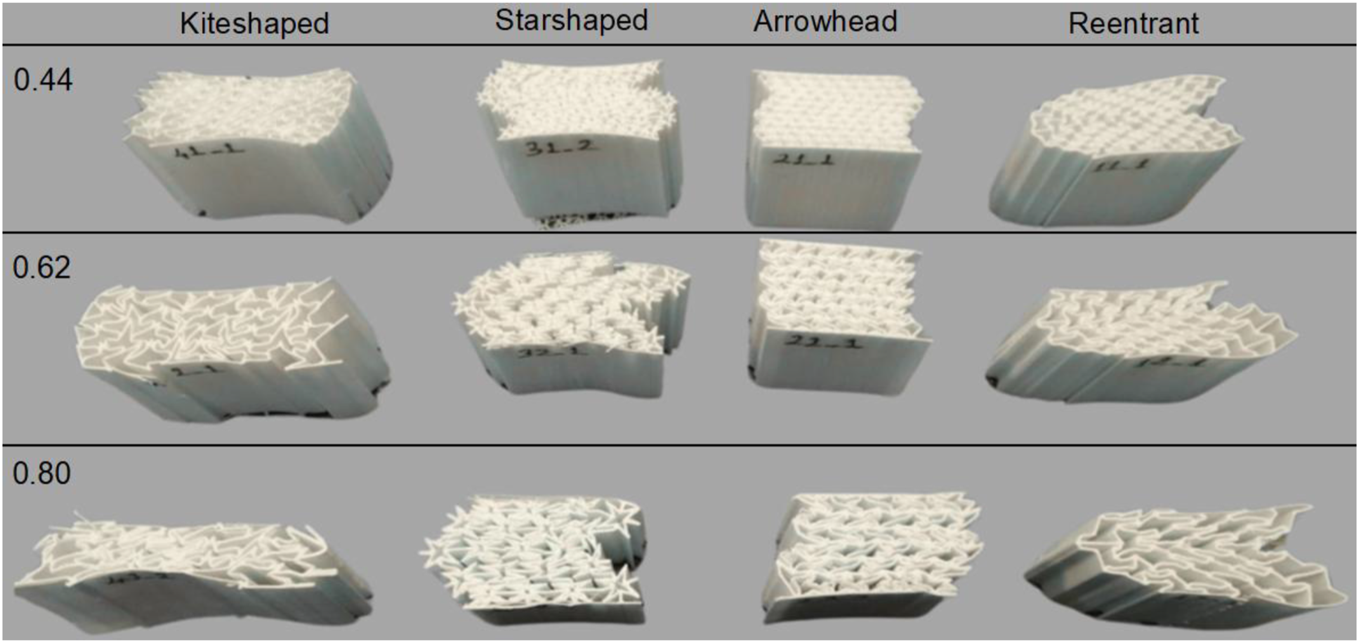
Figure 11(a) and (b) compare the average specific energy absorption (SEA) and peak contact force (PCF) values across core geometries and wall thicknesses, including standard deviation bars. The plotted trends support earlier observations and highlight the influence of both unit cell topology and relative wall thickness on mechanical performance under quasi-static loading. Average specific energy absorption (SEA) (a), and peak contact force (PCF) (b) values auxetic specimens with different core geometries and wall thicknesses under quasi-static compression. Error bars indicate standard deviations. AH: Arrowhead, RE: Reentrant, SS: Starshaped, KS: Kiteshaped.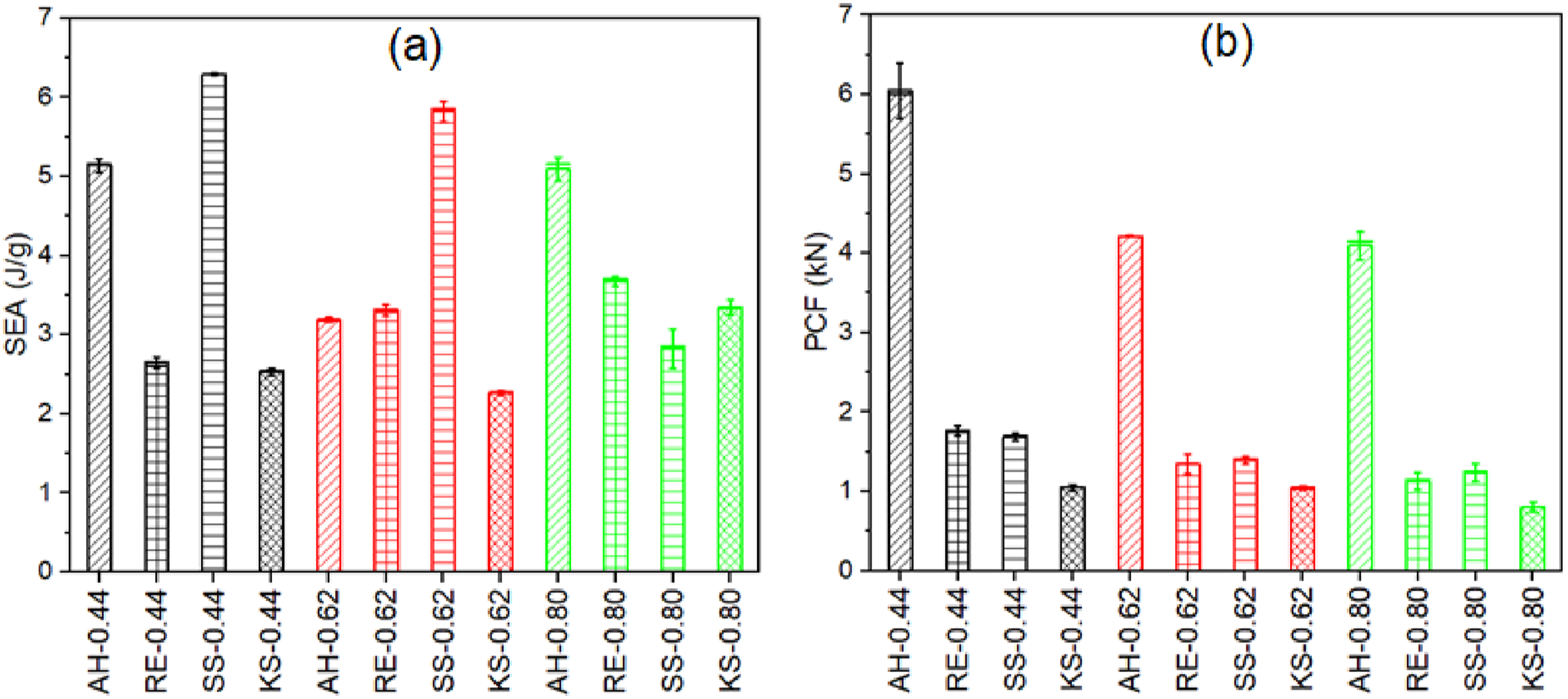
Results of low-velocity impact experiments
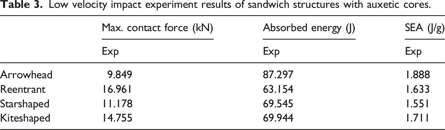
Figure 12 and Table 3 present the low-velocity impact response of sandwich composites with different auxetic core geometries and key properties determined from experiments, respectively. All specimens have the same face materials which were made of glass fiber-reinforced epoxy composites, ensuring that differences in impact behavior are solely attributed to core geometry. The force-displacement, force-time, and velocity-displacement curves provide a comprehensive assessment of their energy absorption characteristics. Low velocity impact test results of auxetic core sandwich composites. Low velocity impact experiment results of sandwich structures with auxetic cores.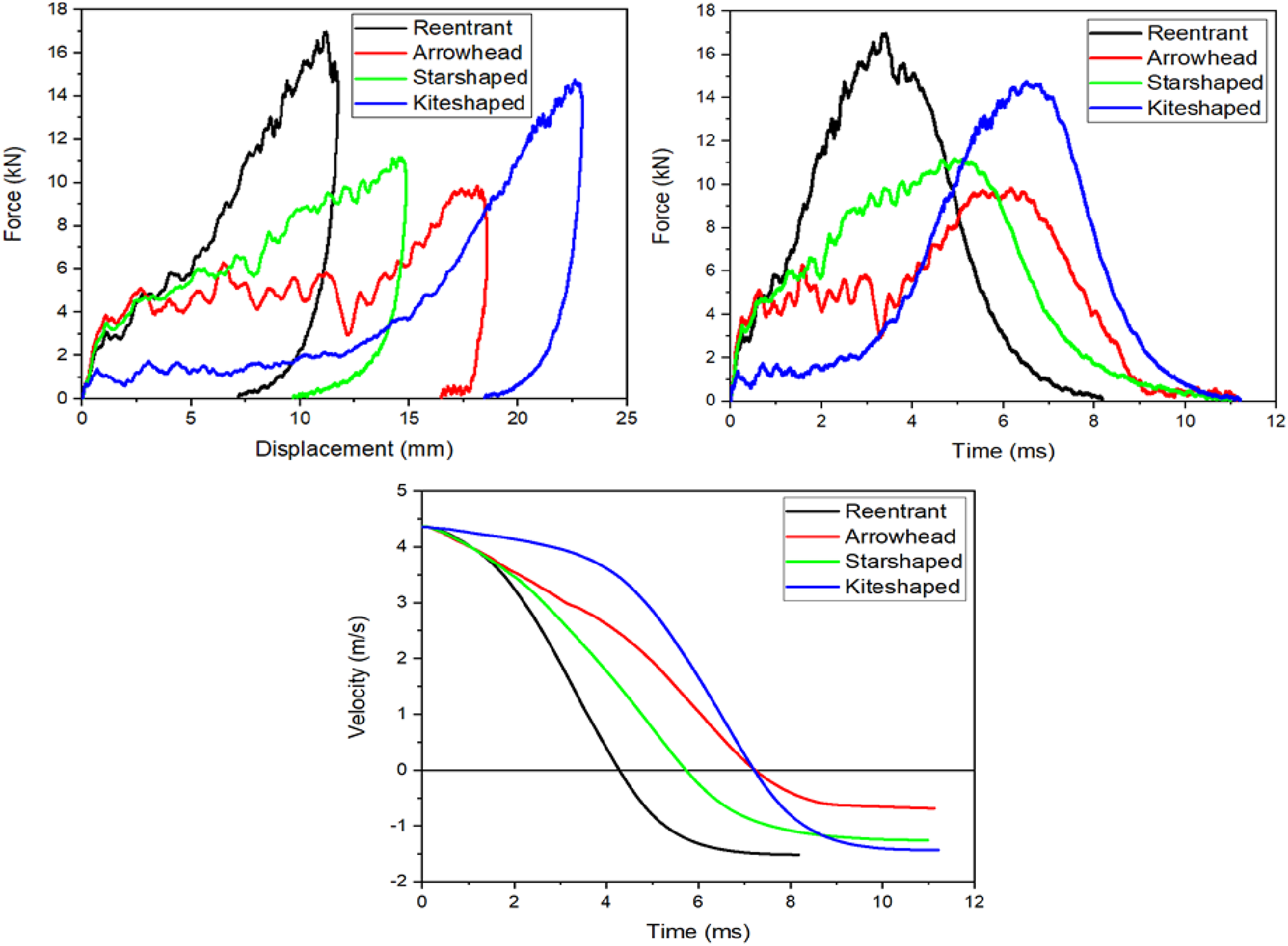
The reentrant core sandwich composite specimen exhibited the highest peak force, reaching approximately 17 kN within a short displacement range. This indicates a stiff response with rapid load transfer, enabling effective impact force resistance. However, the sharp peak in the force-time graph suggests a sudden failure mechanism, likely to be due to localized core crushing or densification. The velocity-time curve confirms that the reentrant structure decelerates the fastest, meaning it absorbs energy in a highly concentrated manner, which could lead to localized damage rather than progressive energy dissipation.
The arrowhead core demonstrates a lower peak force than the reentrant structure but maintains a broader force-time curve, indicating a more gradual energy absorption process. The force-displacement graph shows a smoother profile, suggesting that the core undergoes progressive deformation rather than abrupt failure. Its velocity-displacement curve follows a moderate deceleration trend, signifying an improved balance between force resistance and energy dissipation.
The starshaped core exhibits an impact response like the arrowhead structure, with a slightly lower peak force. The force-displacement curve suggests a stepwise deformation mechanism, likely due to the geometric arrangement of the auxetic cells. This structure provides a compromise between peak force resistance and sustained energy dissipation, as evidenced by its force-time curve, which shows a gradual decline after reaching peak load.
The kiteshaped core has the lowest peak force but maintains the longest impact duration. The force-time curve exhibits a delayed peak, indicating a gradual buildup of resistance as the impact progresses. The velocity-displacement graph shows that this structure experiences the slowest deceleration, meaning it distributes the impact energy over a longer period. This behavior suggests that the kiteshaped core is particularly effective in mitigating impact forces through controlled deformation, reducing the likelihood of sudden failure.
Overall, the results highlight distinct trade-offs among the tested auxetic core geometries. The reentrant structure provides the highest stiffness and peak force resistance but may be prone to brittle failure under high impact loads. In contrast, the kiteshaped core exhibits the most progressive energy dissipation, making it suitable for applications where controlled impact mitigation is crucial. The arrowhead and starshaped cores offer intermediate behaviors, balancing force resistance with energy absorption efficiency. These findings provide valuable insights into the optimization of auxetic core sandwich composites for impact-resistant applications.
Although the primary focus of this study was on the influence of core geometry, it is important to acknowledge that the GFRP face sheets also contribute to the overall impact response of the sandwich structures. In all specimens, the face sheets were manufactured using identical material, layup, and thickness, thereby ensuring consistent boundary conditions. The GFRP face sheets also played a role in dissipating a part of the impact energy, thereby mitigating the load transmitted to the auxetic cores.
Figure 13 shows that the post-impact damage assessment of sandwich structures with varying core geometries provides valuable insights into their energy absorption mechanisms and failure modes under low-velocity impact conditions. The damage patterns observed on both the impacted surface and the internal core structures reveal distinct deformation behaviors influenced by the core topology. Damaged sandwich structures after the low velocity impact experiments.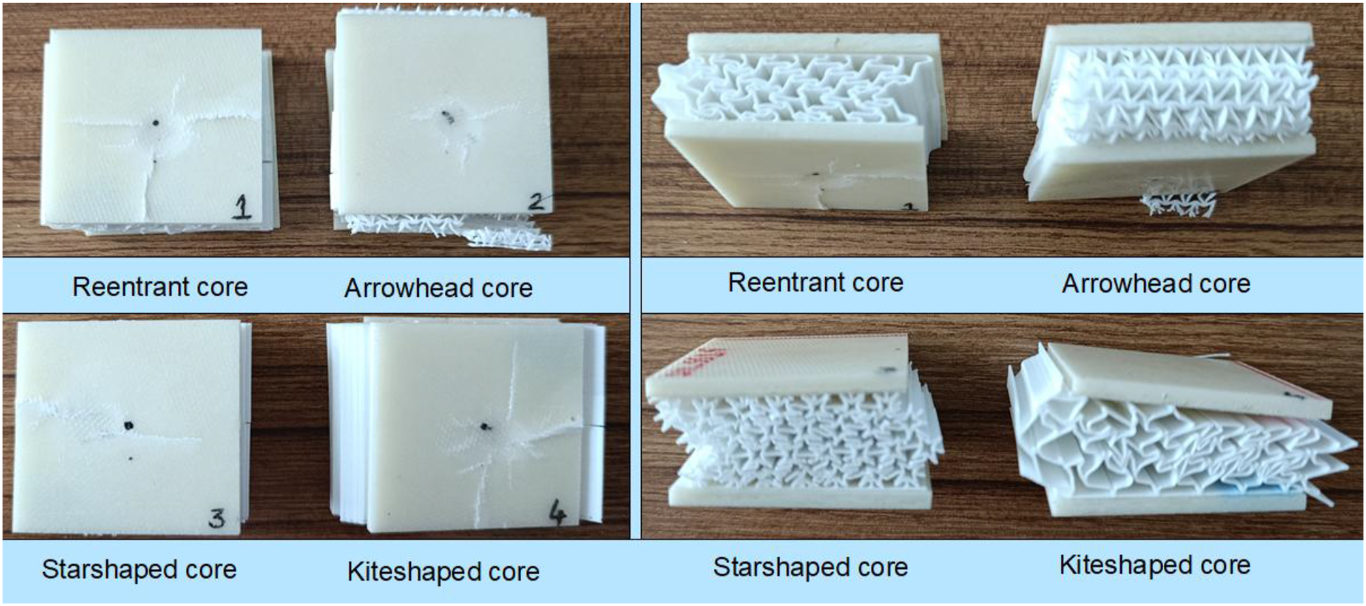
The reentrant core exhibited a localized indentation with radial cracks propagating outward on the impacted surface, indicating efficient stress dissipation. The front-view analysis showed significant densification in the impact zone, suggesting a progressive collapse mechanism. This behavior aligns with the expected deformation characteristics of reentrant auxetic structures, where a negative Poisson’s ratio contributes to enhanced energy absorption through controlled buckling.
In the arrowhead core, a more extensive crack propagation was observed on the impacted surface, indicating higher stress concentration at the impact point. Internally, the core exhibited severe localized crushing and partial delamination at the face-core interface, highlighting a combination of core densification and out-of-plane deformation as dominant failure mechanisms. The relatively lower stability of this structure under impact loads suggests that its energy absorption capability is less efficient compared to the reentrant core.
The starshaped core displayed a more uniform stress distribution, as evidenced by the smaller radial cracks on the impacted surface. The core structure showed controlled layer-by-layer collapse, which limited excessive deformation while maintaining a balanced energy dissipation response. This indicates that the starshaped configuration effectively mitigates impact damage by distributing loads more evenly across the structure.
Conversely, the kiteshaped core exhibited a more pronounced impact indentation with visible radial cracks, indicating moderate energy absorption. The front-view analysis revealed significant out-of-plane deformation and distinct folding patterns within the core, suggesting a progressive collapse mechanism. However, the structure demonstrated localized failure, implying that its stability under impact loading is lower than that of the reentrant and starshaped cores.
Overall, the results suggest that the reentrant and starshaped cores offer superior impact resistance due to their ability to undergo controlled progressive failure while efficiently dissipating impact energy. The arrowhead and kiteshaped cores, on the other hand, exhibit higher stress concentrations and localized failure, making them less favorable for applications requiring enhanced impact resistance. These findings are consistent with quasi-static compression results, where the reentrant and starshaped cores demonstrated superior mechanical performance. Specifically, the reentrant core exhibited the highest peak forces under both loading conditions, indicating strong load-bearing capability, while the starshaped core showed the highest specific energy absorption under quasi-static tests, reflecting superior energy dissipation efficiency. The observations highlight the significance of core topology in optimizing the impact behavior of sandwich structures, providing crucial insights for the design of lightweight, impact-resistant composites.
Numerical results
Deformation modes observed experimental and numerical studies for 0.44 mm wall thickness specimens having different unit cell geometries at different strain values.
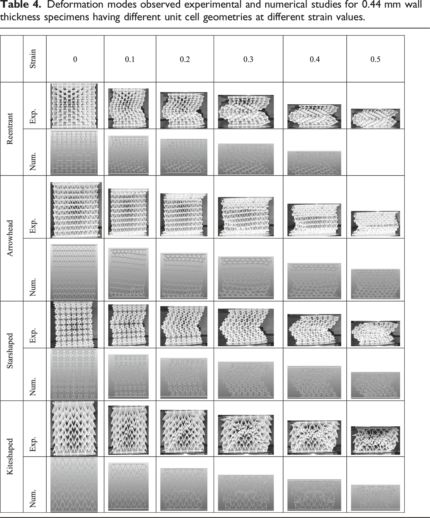
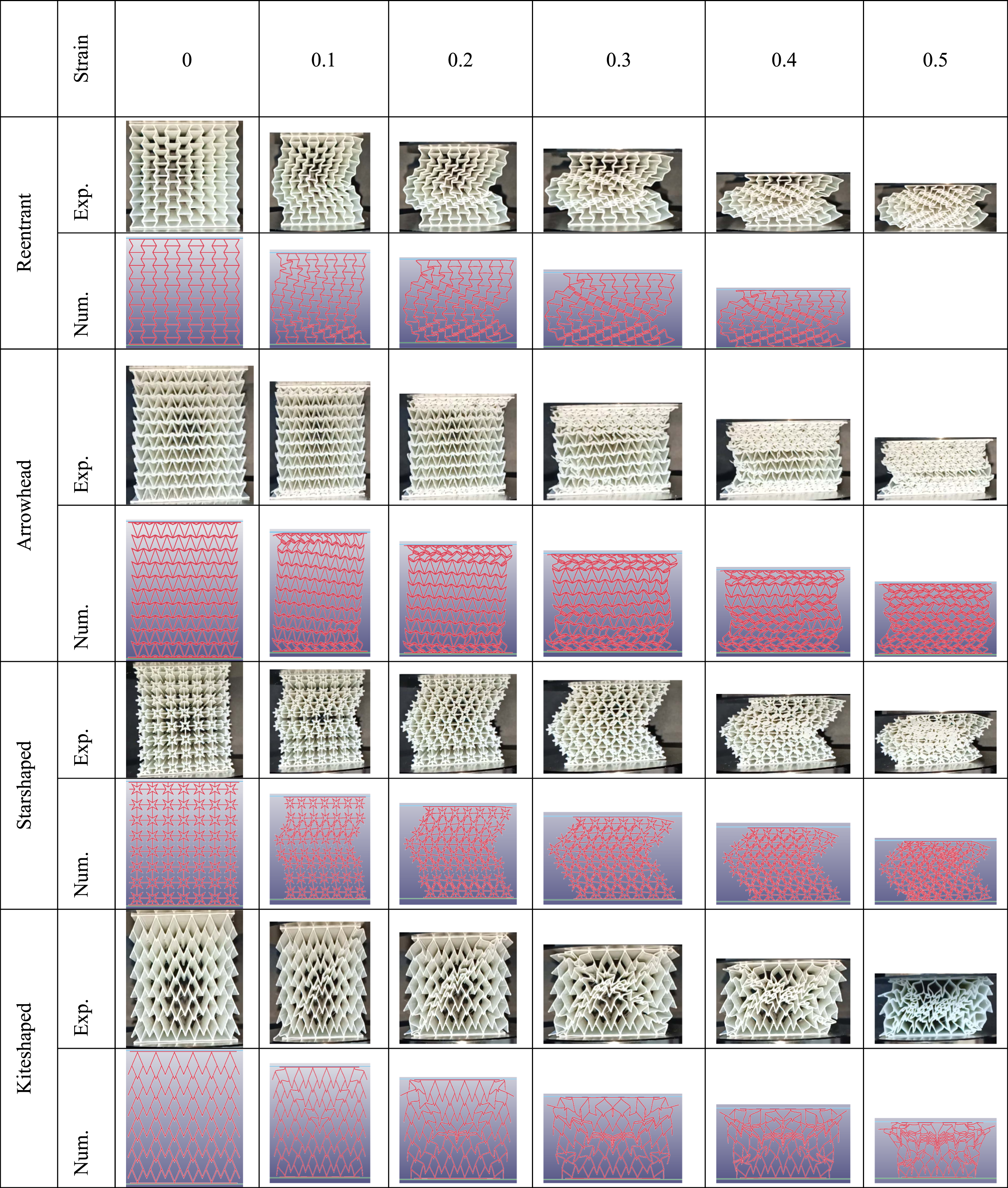
The reentrant structure exhibits a gradual and homogeneous deformation pattern, with progressive inward folding of the unit cells. Both experimental and numerical results indicate that deformation initiates at the top and propagates downward as strain increases. Up to 0.3 strain, the structure undergoes a uniform collapse, but beyond this point, densification begins, leading to a significant increase in force, as seen in the force-displacement graph. The numerical model successfully captures the global deformation mode, although slight differences in localized buckling regions are observed.
The arrowhead geometry demonstrates a different collapse mechanism compared to the reentrant structure. The deformation initiates from the middle region rather than uniformly from the top, leading to localized buckling at intermediate strain levels. Experimental and numerical results show good agreement in terms of collapse patterns, with the primary difference being in the exact location of the initial failure. The force-displacement curve exhibits periodic fluctuations, suggesting a stepwise failure mode, which is characteristic of structures with concentrated stress regions.
The starshaped auxetic structure undergoes a more distributed deformation pattern with a combination of local buckling and global folding. Up to 0.2 strain, the structure maintains its integrity, but beyond this point, significant plastic deformation occurs. The experimental images show a slight misalignment in certain regions, likely due to imperfections in manufacturing. The numerical results capture the overall deformation trend, although some differences in localized failure zones are observed. The force-displacement curve for this structure indicates a more stable response compared to the arrowhead geometry, with a smoother force progression.
The kiteshaped structure displays a highly localized collapse mechanism, with deformation initiating from the edges and propagating toward the center. This is clearly observed in both experimental and numerical results, where the side regions begin to fold first. At higher strain values (0.4 and 0.5), the structure experiences significant densification, leading to a steep increase in force. The numerical model effectively predicts this behavior, though minor discrepancies are present in the exact buckling locations.
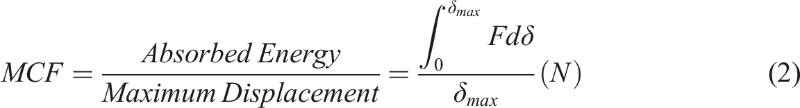
Figures 14a–d, 15a–d, 16a–d and Table 5 show a detailed experimental and numerical comparison for all compression test cases and critical parameters relevant to the performance of auxetic geometries. Equations (1) and (2) are used to calculate specific energy absorption (SEA) and mean crushing force (MCF) parameters, respectively.
50
Peak Crushing Force (PCF) refers to the maximum load observed during the initial collapse phase of a structure, typically occurring before significant densification. It corresponds to the first major load peak, often within the elastic or early plastic region, and is a critical parameter for evaluating the load-carrying capacity of energy-absorbing structures. Comparison of experimental and numerical results for 0.44 mm wall thickness geometries. (a) Arrowhead, (b) Reentrant, (c) Starshaped, (d) Kiteshaped. Comparison of experimental and numerical results for 0.62 mm wall thickness geometries. (a) Arrowhead, (b) Reentrant, (c) Starshaped, (d) Kiteshaped. Comparison of experimental and numerical results for 0.80 mm wall thickness geometries. (a) Arrowhead, (b) Reentrant, (c) Starshaped, (d) Kiteshaped. Quasi-static experiment results of auxetic structures.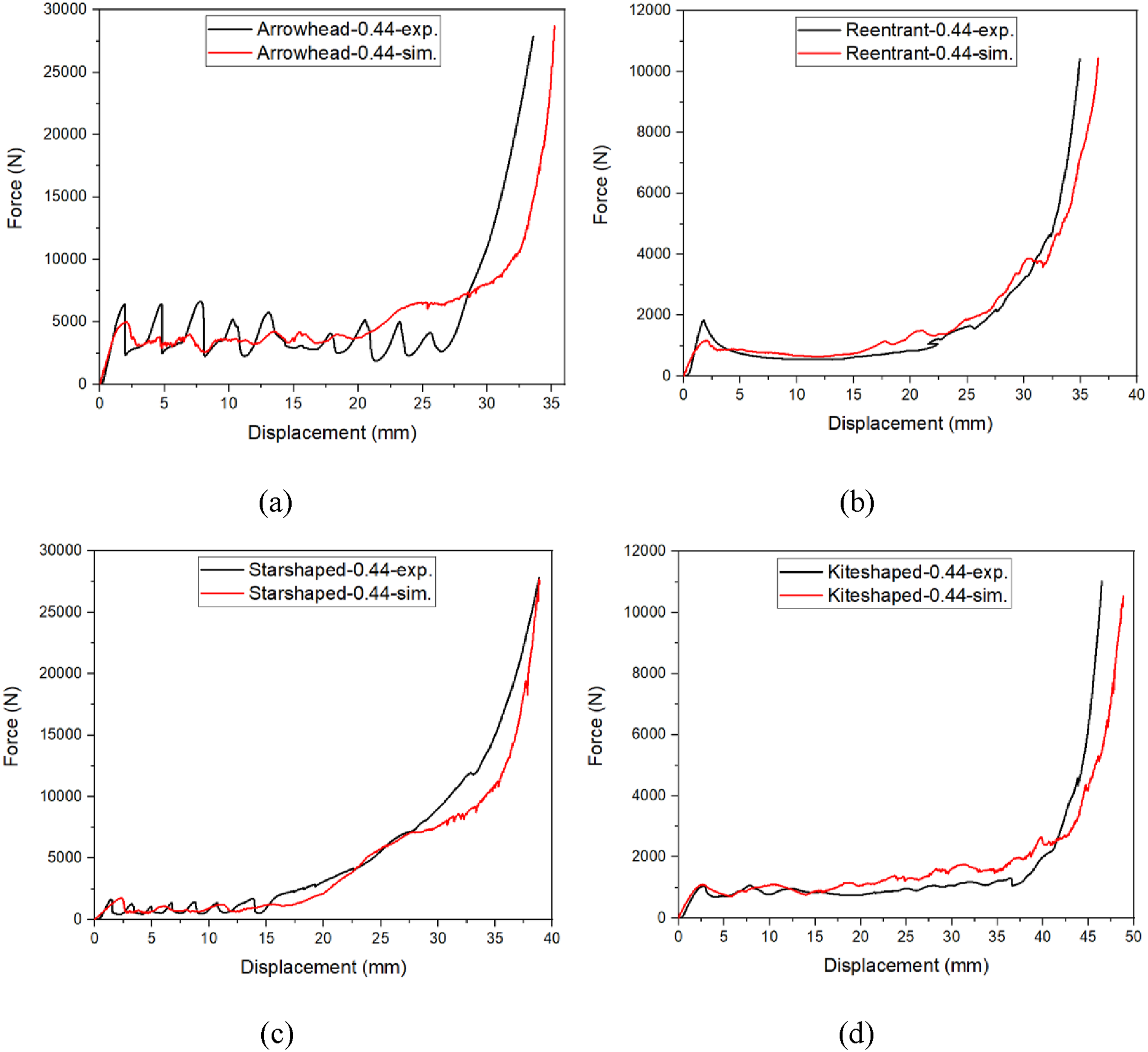
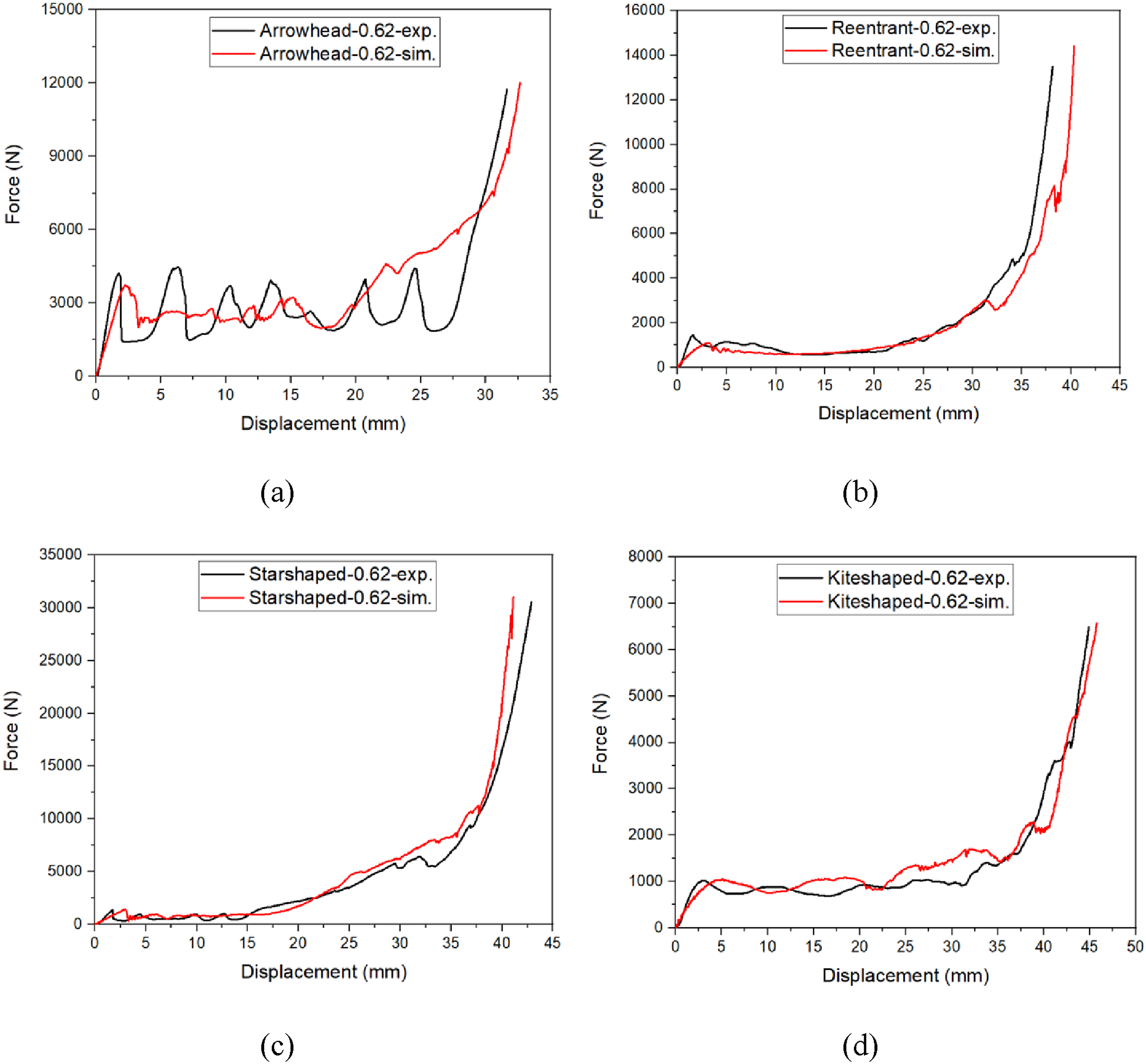
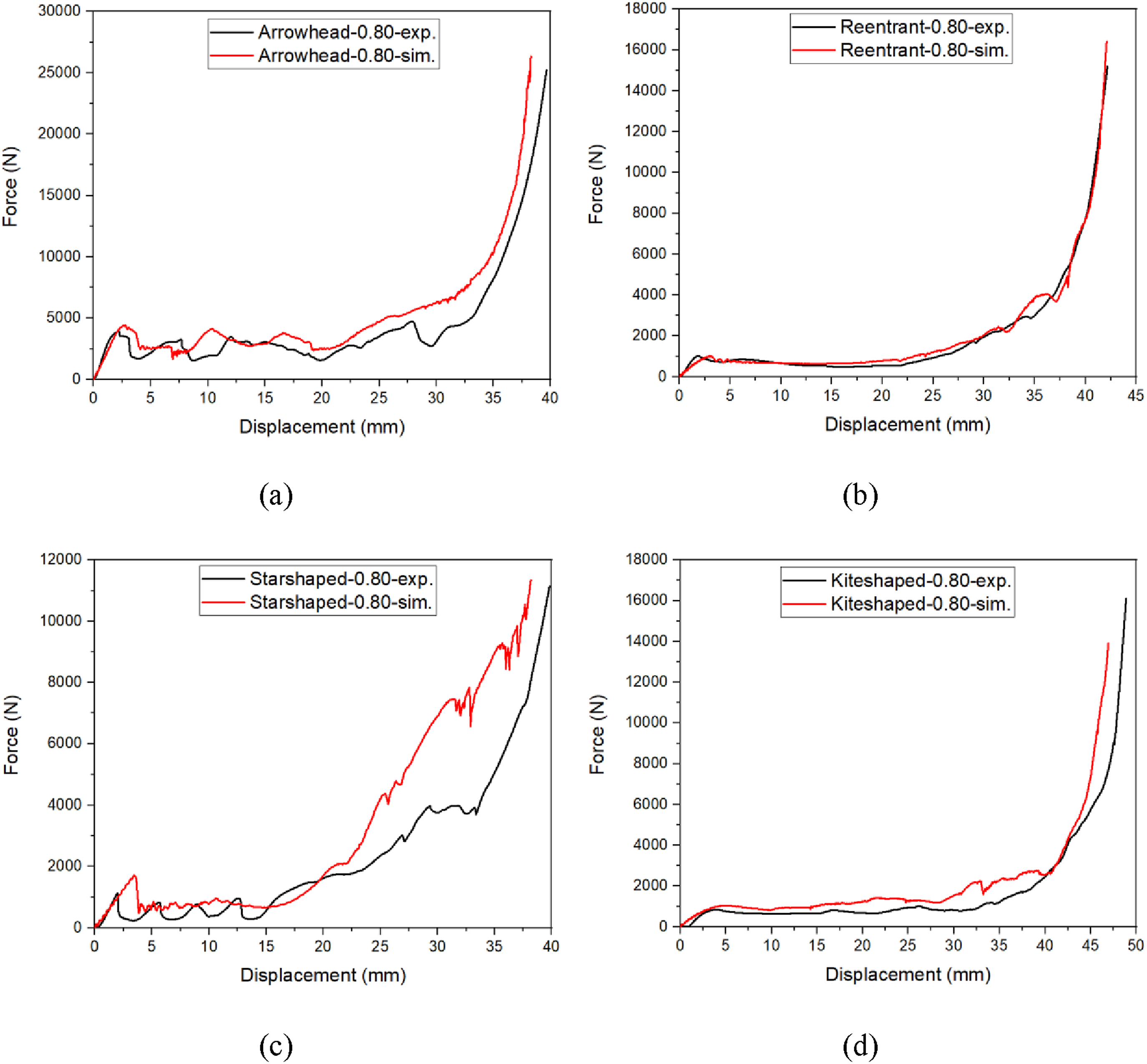
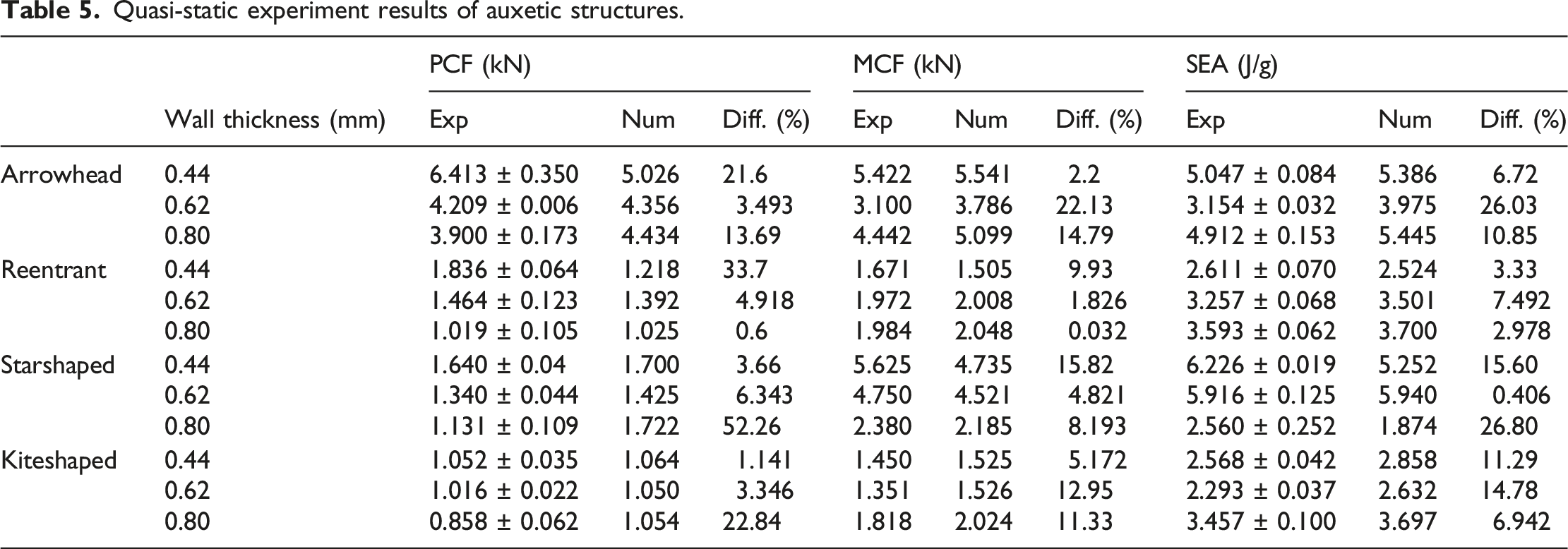
In Table 5, the lowest deviation in peak crushing force was observed in the reentrant structure with 0.80 mm wall thickness (0.6%), confirming excellent numerical prediction. In contrast, the starshaped structure with 0.80 mm wall thickness showed the largest difference (52.3%), likely due to local buckling and geometric imperfections during fabrication. Among all tested designs, the starshaped structure with 0.44 mm thickness exhibited the highest specific energy absorption, reaching 6.23 J/g, while reentrant geometries provided more stable and consistent force responses across varying wall thicknesses. These findings suggest that the numerical model reliably captures the crushing behavior of auxetic structures in most cases, although some geometries remain more sensitive to imperfections and deformation instability.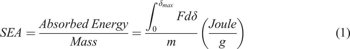
Overall, the experimental and numerical results exhibit strong agreement in capturing the global deformation mechanisms of different auxetic geometries. However, minor variations in local collapse patterns are observed, which can be attributed to factors such as manufacturing imperfections, boundary conditions, and material inconsistencies. The force-displacement curves provide further validation, with structures exhibiting different energy absorption characteristics based on their deformation modes.
Finally, Figure 17 presents a critical comparison of arrowhead and reentrant geometries auxetic structures between this study and literature.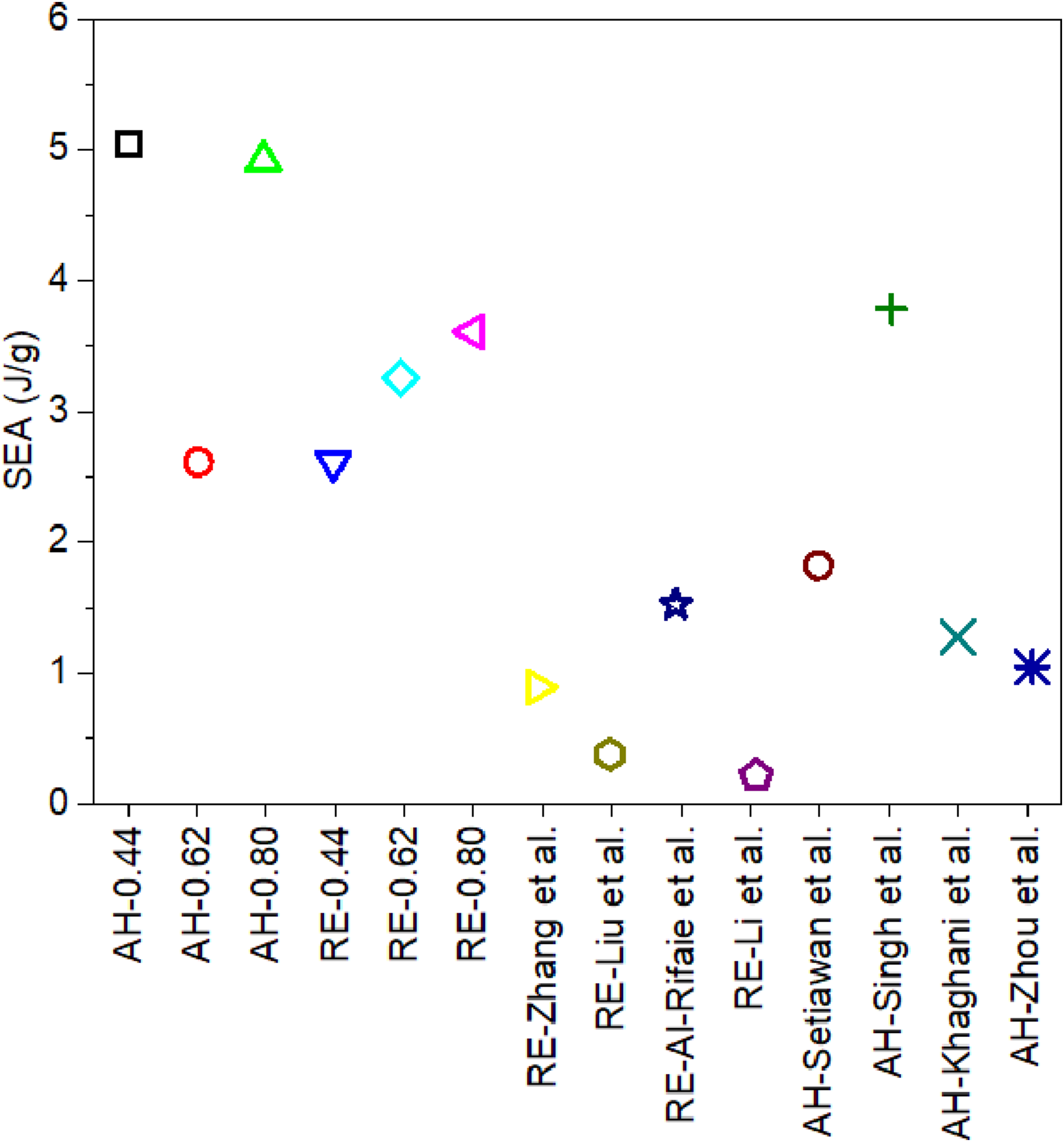
Conclusions
In this study, the effects of auxetic unit cell geometry and wall thickness on the quasi-static and low-velocity impact response of GFRP sandwich composites were investigated, and the key findings are summarized below. • Among the tested geometries, the starshaped structure with 0.44 mm wall thickness demonstrated the highest specific energy absorption (6.226 J/g) under quasi-static compression, highlighting its superior energy dissipation capability. • The reentrant geometry with 0.80 mm wall thickness yielded the lowest deviation (0.6%) between experimental and numerical peak crushing force, confirming the model’s high reliability for stable geometries. • The largest discrepancy (52.3%) was observed in the starshaped geometry with 0.80 mm wall thickness, indicating that certain designs are more sensitive to local buckling and manufacturing imperfections. • In low-velocity impact tests, the arrowhead core absorbed the highest energy (87.30 J) and achieved the highest SEA (1.89 J/g), suggesting a more progressive collapse behavior compared to the stiffer reentrant core, which showed the highest peak force (16.96 kN). • The kiteshaped core exhibited the longest impact duration and smoothest deceleration, which may be advantageous for applications prioritizing gradual energy dissipation and reduced peak loading. • Overall, results confirm that auxetic geometry and wall thickness are critical parameters in tailoring energy absorption and failure modes of sandwich composites under dynamic loading.
Footnotes
Consent to participate
All authors have reviewed the final manuscript and consent to its submission.
Author contributions
Ali İmran Ayten: Conceptualization, Methodology, Data Curation, Writing - Original Draft, Writing - Review & Editing, Visualization, Supervision. Bekir Keskin: Investigation, Data Curation, Writing - Original Draft, Writing - Review & Editing. Ameen Topa: Validation, Formal analysis, Writing - Original Draft, Writing - Review & Editing, Visualization.
Funding
The authors received no financial support for the research, authorship, and/or publication of this article.
Declaration of conflicting interests
The authors declared no potential conflicts of interest with respect to the research, authorship, and/or publication of this article.
Data Availability Statement
The data that support the findings of this study are available from the corresponding author upon reasonable request.
Declaration of generative AI and AI-assisted technologies in the writing process
During the preparation of this work the author(s) used ChatGPT in order to improve readability of the paper. After using this tool/service, the authors reviewed and edited the content as needed and take full responsibility for the content of the publication.