
Abstract
In this study, a radar-absorbing honeycomb core sandwich structure (RAHSS) was developed to simultaneously achieve high radar-absorbing performance, structural load-bearing capability, and weight efficiency in radar-absorbing structures (RASs). By employing nickel-coated glass fabric as both the face sheets and honeycomb core, the proposed RAHSS simultaneously achieves enhanced electromagnetic attenuation, improved mechanical performance, and significant weight reduction compared to conventional laminate-type RASs. The glass fabric was uniformly coated with nickel via electroless plating to tailor its electromagnetic properties, and the surface characteristics of the resulting fabric were systematically analyzed using scanning electron microscopy, energy-dispersive X-ray spectroscopy, and X-ray photoelectron spectroscopy. The electromagnetic design of the RAHSS was optimized using CST Microwave Studio, and its radar-absorbing performance was experimentally evaluated through reflection loss (RL) and radar cross-section (RCS) measurements. The mechanical performance of the RAHSS was assessed through three-point bending tests and directly compared with that of a laminate-type RAS fabricated from the same constituent materials. Results demonstrate that the RAHSS effectively attenuates incident electromagnetic waves over a target frequency range and achieves substantial backscattered signal reduction compared to a perfect electric conductor. It exhibits a load-to-weight ratio approximately 2.2 times higher than that of the laminate-type RAS, confirming its superior bending efficiency. Overall, the proposed RAHSS offers a lightweight, mechanically robust, and electromagnetically efficient solution for next-generation stealth structures in aerospace and defense applications.
Keywords
Introduction
For strategic fighter aircraft and weapon system operations, detection performance must be considered by minimizing the radar cross-section (RCS) detected by radar systems.1–7 Several technologies have been reported for RCS reduction, including body shaping,8,9 radar-absorbing materials (RAMs),10,11 and radar-absorbing structures (RASs).12,13 Although body shaping forms the basis of stealth technology, excessive shaping can negatively impact structural integrity and aerodynamic performance. 14 RAMs have low densities, resulting in higher weights and requiring frequent maintenance, which reduce their economic benefits. 15 Meanwhile, RASs address the limitations of RAMs, offering excellent radar-absorbing performance with a large load-bearing capacity. RASs are typically fabricated using glass-fabric-based composites. As glass fabrics lack necessary electromagnetic properties required to be used for RASs, the electromagnetic characteristics of a fabric or matrix must be modified to enhance the corresponding composite’s loss tangent. Studies have focused on fiber control12,13,16 and matrix control through nanoparticle dispersion for improving loss tangent.17–19 Additionally, extensive research has been conducted on circuit-analog absorbers based on frequency-selective sheets as they do not require modifications to the composite’s electromagnetic characteristics.20–22 Carbon nanotubes (CNTs)23,24 and carbon black25,26 are commonly used as nanoparticles dispersed in a matrix to impart electromagnetic properties to that matrix. These nanoparticles enhance the loss tangent of a matrix by acting as lossy fillers. However, they may aggregate in a matrix owing to van der Waals forces and electrostatic interactions caused by potential energy at the particle surface. 27 This aggregation can lead to various effects, including deterioration of the structure’s mechanical properties. 28
To modify a fabric for improving the loss tangent, its surface is coated with metals using methods like electroless plating or sputtering. This process increases the fabric’s loss tangent, helping in minimizing the structure’s weight while maintaining radar-absorbing performance. 13 Electroless plating provides a uniform coating on the fabric surface, offering excellent reproducibility and eliminating drawbacks associated with particle agglomeration in dispersion methods. A thin-walled flat composite structure can possess excellent in-plane load-bearing capacity for tensile and compressive forces; however, its resistance to bending forces is low owing to its small thickness, reducing bending stiffness. Additionally, a laminate-type RAS requires a thickness of 1.82–3.00 mm for adequate radar-absorbing performance.13,19,29 Consequently, laminate-type RASs face limitations in further reducing structural weight owing to their shape characteristics.
Meanwhile, a honeycomb core sandwich composite consists of a low-density honeycomb core with excellent bending stiffness at the center and thin face sheets being bonded to the top and bottom. This design is widely used in various structures owing to its lightweight nature, superior mechanical properties, and good insulation performance.30,31 When used in aircraft structures, its superior bending properties compared to laminate structures provide enhanced resistance to bending and buckling loads caused by flight stresses.32–34 Using a honeycomb core sandwich composite in RAS fabrication improves radar-absorbing performance while maintaining lightweight nature. Owing to these benefits, extensive studies have been conducted on RASs that offer excellent stealth capabilities with a lightweight design by incorporating a honeycomb core sandwich composite into lossy materials.16,35,36 Kwak et al. 16 introduced a honeycomb core sandwich RAS with excellent wide-band radar-absorbing performance using nickel-coated glass fabric. They also assessed the mechanical properties of the honeycomb core RAS through tensile, compression, and interlaminar shear strength tests. Baek et al. 35 proposed a honeycomb core sandwich RAS using a film with periodic patterns. They measured reflection loss based on the pattern arrangement and wave incidence direction. Choi et al. 36 developed a honeycomb core sandwich RAS using glass fiber/epoxy–multiwalled CNTs, analyzed its radar-absorbing performance, and verified wave attenuation through multiple reflections within the core.
Most previous studies investigating honeycomb core sandwich RASs have primarily focused on radar-absorbing performance or mechanical strength independently, while the coupled advantages of radar absorption, load-bearing capability, and weight efficiency have not been systematically analyzed. In this study, we developed a radar-absorbing honeycomb core sandwich structure (RAHSS) with exceptional performance in a target frequency range and validated its performance through simulations and experiments. Moreover, the mechanical properties of the proposed RAHSS were evaluated through comparison with a laminate-type RAS 37 using mechanical tests. To simultaneously satisfy electromagnetic loss requirements and structural integrity, nickel was uniformly coated onto a glass fabric via electroless plating. The Ni-coated glass fabric was then used to fabricate a flat-plate-type face sheet and hexagonal honeycomb core. To assess the radar-absorbing performance of the RAHSS, its return loss (RL) and RCS reduction were measured using an antenna-based measurement system. Its bending properties were evaluated through a three-point bending test and compared with those of a laminate-type RAS. Furthermore, the potential for structural weight reduction in low-probability-of-intercept aircraft applications was systematically evaluated by correlating electromagnetic performance, mechanical behavior, and density.
Design and fabrication
Materials and design
In this study, a plain-weave glass fabric (width: 1.5 m; length: 100 m) supplied by Minhu Composite Co. Ltd. (Republic of Korea) and an epoxy resin provided by Kukdo Chemical Co. Ltd. (Republic of Korea) were used to fabricate a composite sandwich structure. Nickel was coated onto the fabric surface through electroless plating, ensuring uniform thickness and enabling the simultaneous coating of large fabric amounts, to impart lossy properties to the glass fabric.16,20,37,38 The elemental compositions of the Ni-coated glass fabric were analyzed by scanning electron microscopy (SEM; MIRA3 LM, TESCAN, Czechia), energy-dispersive X-ray spectroscopy (EDS; JSM-7610F, JEOL, Japan), and X-ray photoelectron spectroscopy (XPS; Nexsa, Thermo Fisher Scientific, USA); the corresponding results are shown in Figure 1. Figure 1(a) presents an SEM image comparing pristine and Ni-coated glass fabrics. The pristine fabric exhibits a smooth surface, whereas the Ni-coated fabric displays a dense and uniform distribution of nickel particles. This uniform coating morphology, as confirmed by surface analysis, ensures consistent modification of the fabric’s electromagnetic properties. Although the coating thickness was not directly measured in this study, previous reports employing identical electroless plating conditions on the same type of glass fabric have indicated that the resulting nickel layer typically exhibits a thickness in the range of 40–80 nm.
16
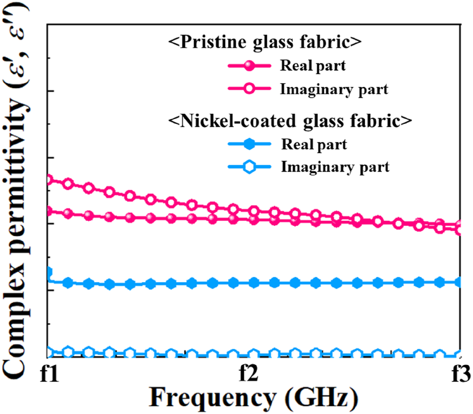
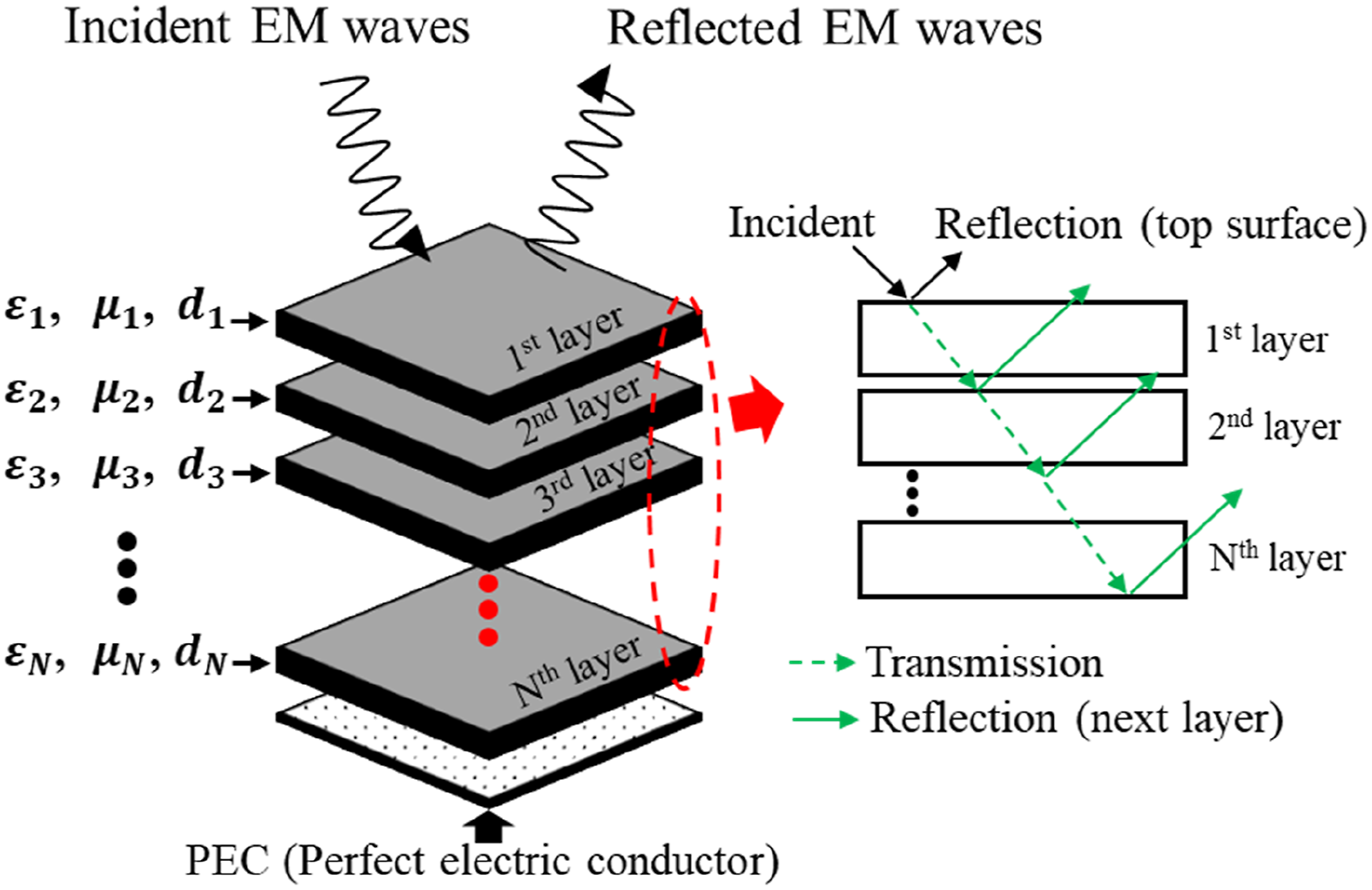
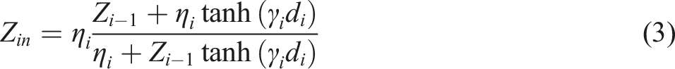
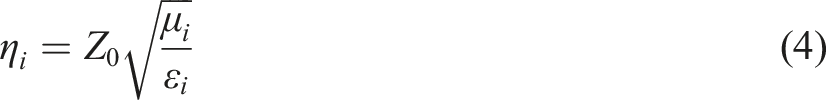
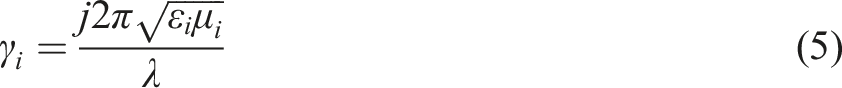
Given that the nickel plating time was carefully controlled under comparable processing conditions in the present work, it can be reasonably inferred that a similar coating thickness was achieved, which is sufficient to impart the intended electromagnetic attenuation characteristics. Furthermore, similar electroless plating approaches reported in prior studies37,38 have demonstrated that such uniform nickel coatings effectively contribute to microwave attenuation. The EDS results indicated no nickel in the pristine fabric, whereas the nickel content increased to approximately 7.04 wt% in the coated fabric (Figure 1(b)). Figure 1(c) shows the XPS results for the electronic surfaces of both fabrics. No distinct peaks corresponding to specific elements were observed in the spectrum of the pristine fabric, whereas a prominent nickel peak (reflecting a high atomic percentage) appeared at 856.1 eV in the XPS spectrum of the Ni-coated fabric. A 200 mm × 200 mm Ni-coated glass fabric/epoxy laminate specimen was fabricated using an autoclave process to obtain the required dielectric properties. The sample was mounted on a holder, and its complex permittivity ( Elemental and surface analysis of the pristine and Ni-coated glass fabrics: (a) scanning electron microscopy (SEM) images, (b) energy-dispersive X-ray spectroscopy (EDS) results, and (c) X-ray photoelectron spectroscopy (XPS) spectrum. Complex permittivity of the pristine glass and Ni-coated glass fabrics measured in a target frequency range. Schematic of the multilayered microwave absorber. (a) Electromagnetic simulation model of the RAHSS. (b) Simulated RL of the RAHSS in a target frequency range.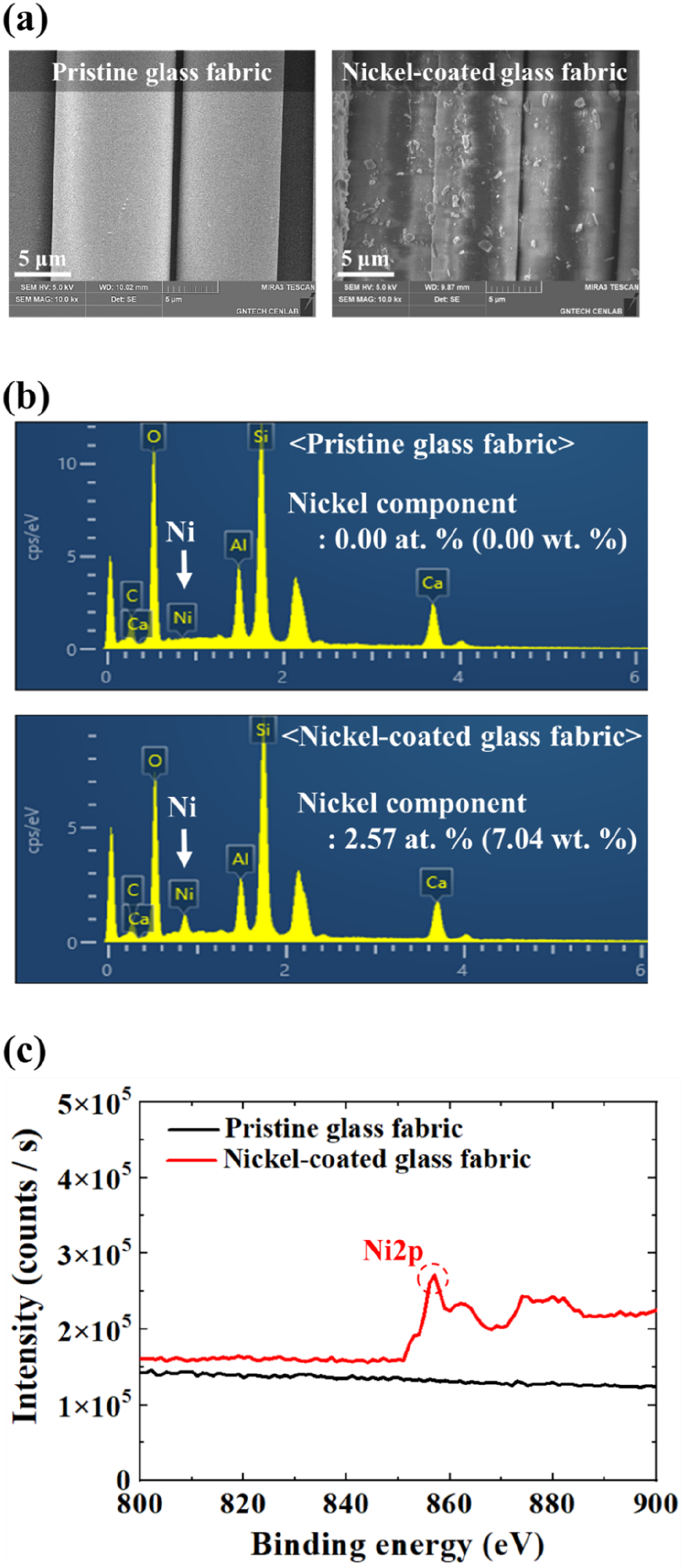
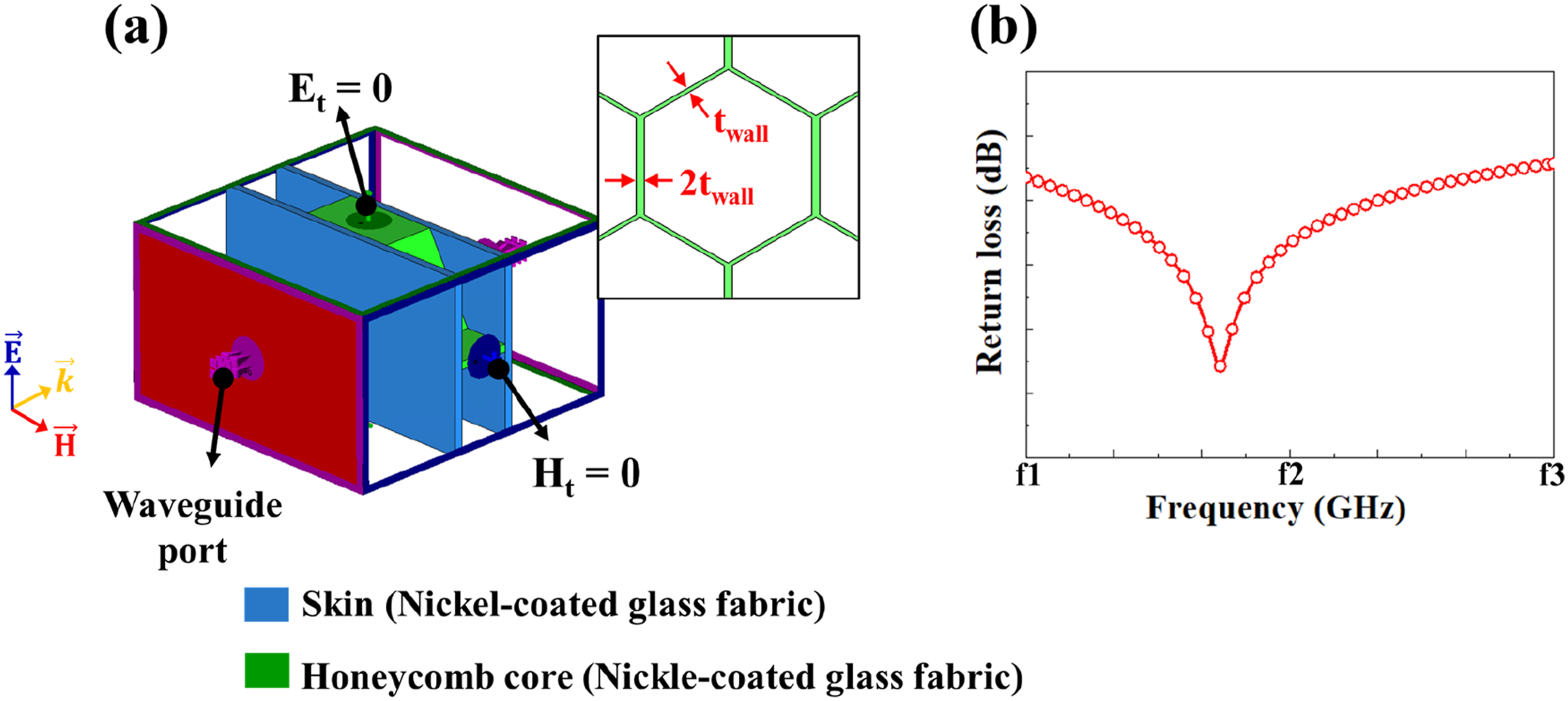

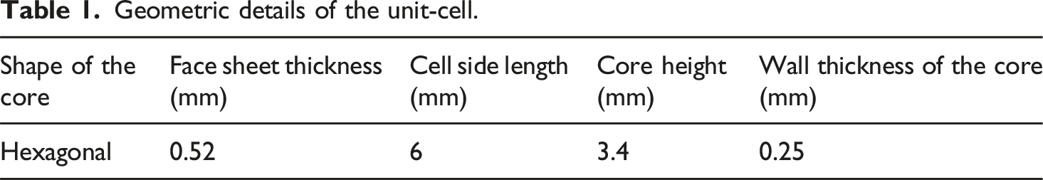
Geometric details of the unit-cell.
Fabrication
In a previous study,
38
a novel fabrication method for a honeycomb core structure was proposed using glass fabric and epoxy, which employed a rack-gear-shaped base plate and inner blocks. Herein, the same fabrication method was utilized to produce the RAHSS, and its effectiveness was validated by evaluating radar-absorbing performance and mechanical properties. The RAHSS was fabricated using Ni-coated glass fabric according to the aforementioned method, as illustrated in Figure 5. The geometric parameters of the honeycomb core, including the cell size, wall thickness, and core height, were selected based on the previously validated configuration summarized in Table 1. These parameters govern electromagnetic wave propagation and attenuation within the honeycomb core by controlling the effective interaction length, multiple internal reflection behavior, and current distribution along the conductive cell walls. Consequently, the selected design provides favorable conditions for enhanced electromagnetic attenuation while maintaining structural consistency and mechanical integrity. Step-by-step fabrication process of the RAHSS using Ni-coated glass fabric and epoxy, incorporating rack-gear-shaped base plate and inner blocks for honeycomb core formation.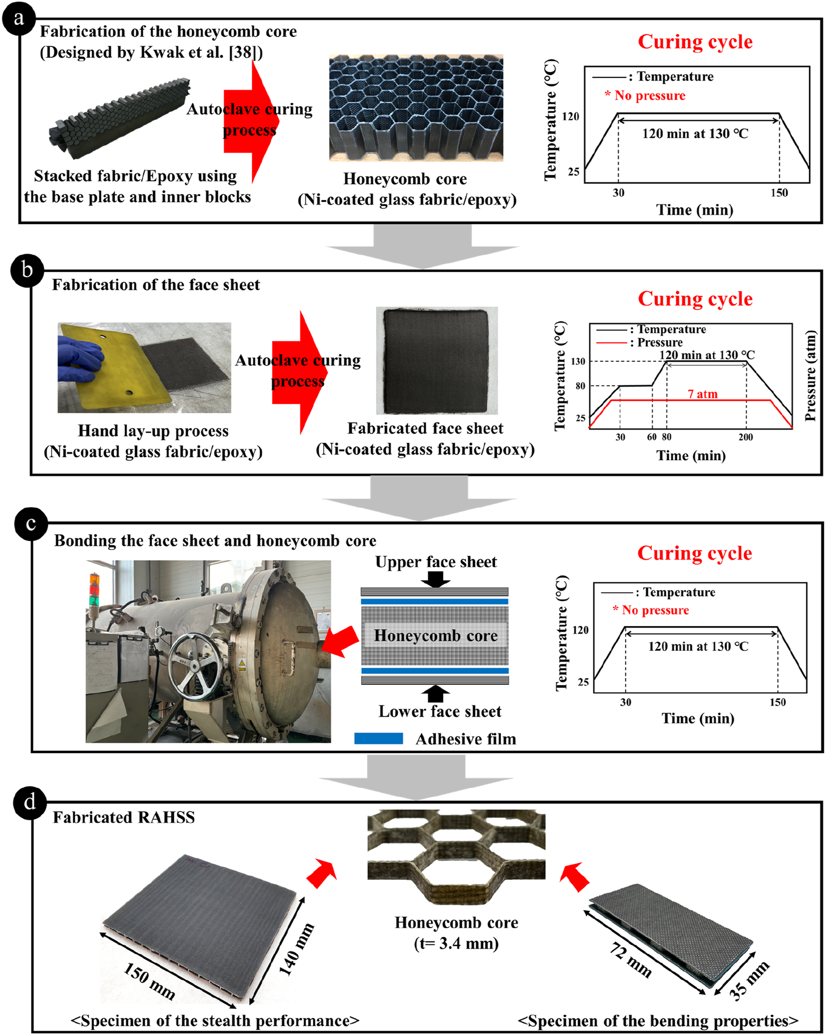
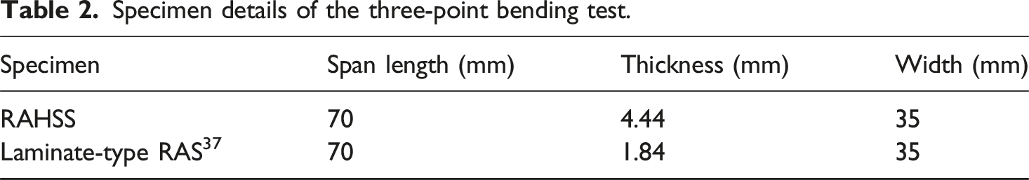
The Ni-coated fabric, impregnated with epoxy, was cut into the desired dimensions and placed on the rack-gear-shaped base plate. Subsequently, the inner blocks, designed as described in Section 2.1, were aligned in the direction of the honeycomb core ribbon and laminated accordingly. This lamination process was repeated in the transverse ribbon direction to ensure the honeycomb core structure. The laminated Ni-coated glass fabric containing epoxy was cured in an autoclave, with the internal temperature gradually raised to 130°C at 1–2°C/min and held for 120 min. Owing to limitations in using the vacuum bag process during curing, the prepared fabric with epoxy at both ends was pressurized with a C-clamp to expel surplus resin from the core. The fabricated core was then machined to a thickness of 3.4 mm based on the optimal design values obtained from simulation. For the face sheet, Ni-coated glass fabric and epoxy were hand laid-up and cured using an autoclave to achieve a thickness of approximately 0.52 mm. The face sheet was cured by heating to 80°C at 1–2°C/min, holding at this temperature for 30 min, then heating to 130°C at the same rate, and maintaining at this temperature for 120 min. The curing pressure remained at 7 atm throughout this process. The cured honeycomb core and face sheet were bonded using AF 163-2K (3M, USA), a thermosetting film adhesive, through secondary bonding at 120°C for 2 h, yielding a 4.44-mm-thick RAHSS. The ribbon direction length and depth of the honeycomb core were machined to 150 and 140 mm, respectively, to assess the radar-absorbing performance of the RAHSS. In this study, we fabricated a laminate-type RAS, proposed by Nam et al. 37 to compare its mechanical properties with those of the RAHSS. They proposed two types of laminate RASs, single- and double-slab types, using Ni-coated glass fabric and epoxy under the same conditions as this study. Both types demonstrated excellent radar-absorbing performance. However, the double-slab type consisted of layers with different stiffnesses, potentially resulting in uneven bending moments during mechanical loading. Therefore, the single-slab-type laminate RAS was selected for the three-point bending test in this study to ensure a more straightforward comparison of flexural properties. The single-slab type RAS was designed to have a total thickness of 1.84 mm to ensure optimal radar-absorbing performance in a target frequency range. Herein, Ni-coated glass fabric was laminated using the same processing conditions as those applied to the face sheet during the second fabrication step illustrated in Figure 5.
Characterization
RL measurement
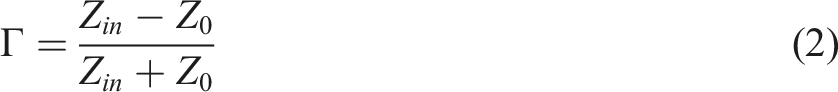
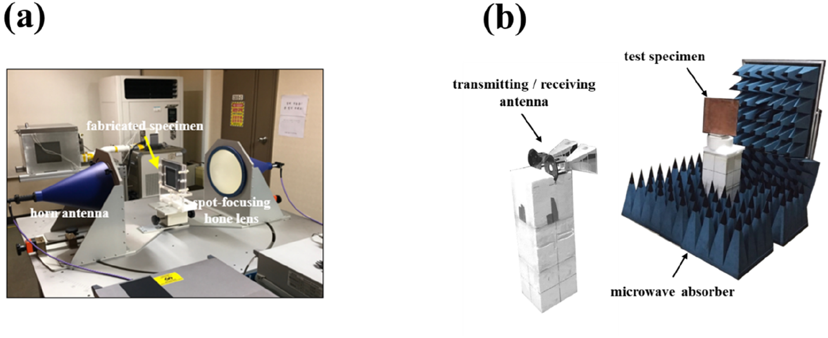
RL was measured in a target frequency range using a free-space measurement system to evaluate the radar-absorbing performance of the proposed RAHSS. A 150 mm × 140 mm RAHSS was secured between two horn antennas using a holder (Figure 6(a)). To reflect incident electromagnetic waves, a copper tape, acting as a perfect electric conductor (PEC), was applied to the back of the RAHSS. Some electromagnetic waves emitted by the horn antennas were reflected by the RAHSS and returned to the antennas. RL [dB] was calculated using MATLAB and a network analyzer. Setup of the radar-absorbing performance test: (a) free-space measurement and (b) RCS measurement system
38
.
RCS measurement
Figure 6(b) shows the quasimonostatic measuring system, where two transmitting and receiving antennas are positioned close to each other, used to measure the RCS reduction performance of the proposed structure. 38 For RCS measurement, the same specimen used for RL measurement was employed. The distance between the specimen and antennas was adjusted to satisfy the far-field condition. RCS was also measured for a copper plate of the same size as the prepared sample to evaluate the RCS reduction performance of the RAHSS. To enhance measurement accuracy by reducing the signal-to-noise ratio, post-processing techniques like coherent integration, time-gating, and coherent subtraction were applied. 42
Three-point bending test
Specimen details of the three-point bending test.
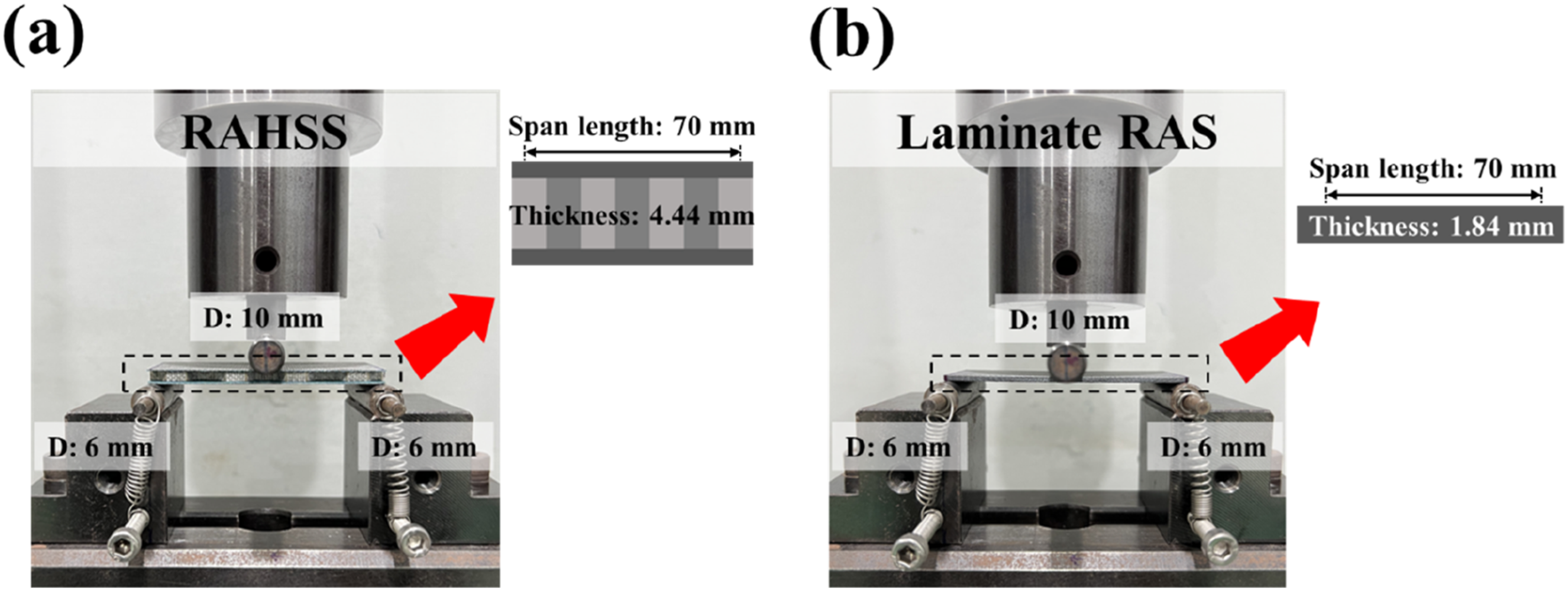
Three-point bending test setup: (a) RAHSS and (b) laminate-type RAS.
Results and discussion
RL measurement result
For evaluating the radar-absorbing performance of the proposed RAHSS, reflection loss (RL) was measured using a free-space measurement system in a designated radar frequency band. The measured results, along with the simulated data, are presented in Figure 8. Both results demonstrated strong absorption performance, consistently exceeding the conventional radar-absorbing threshold. The overall trend of the RL curves revealed a strong agreement between simulation and experiment, with both exhibiting distinct resonance behavior. Notably, both results showed resonance peaks at closely aligned frequency points, confirming the reliability of the simulation model and effectiveness of the proposed structure. The slight error observed in the resonance peak is attributed to shape variations occurring during actual fabrication. The fabricated composite showed a small thickness difference compared to the optimal design, and the adhesion layer bonding the face sheet to the core was not accounted for in finite element analysis. Comparison of simulated and measured RL results of the RAHSS.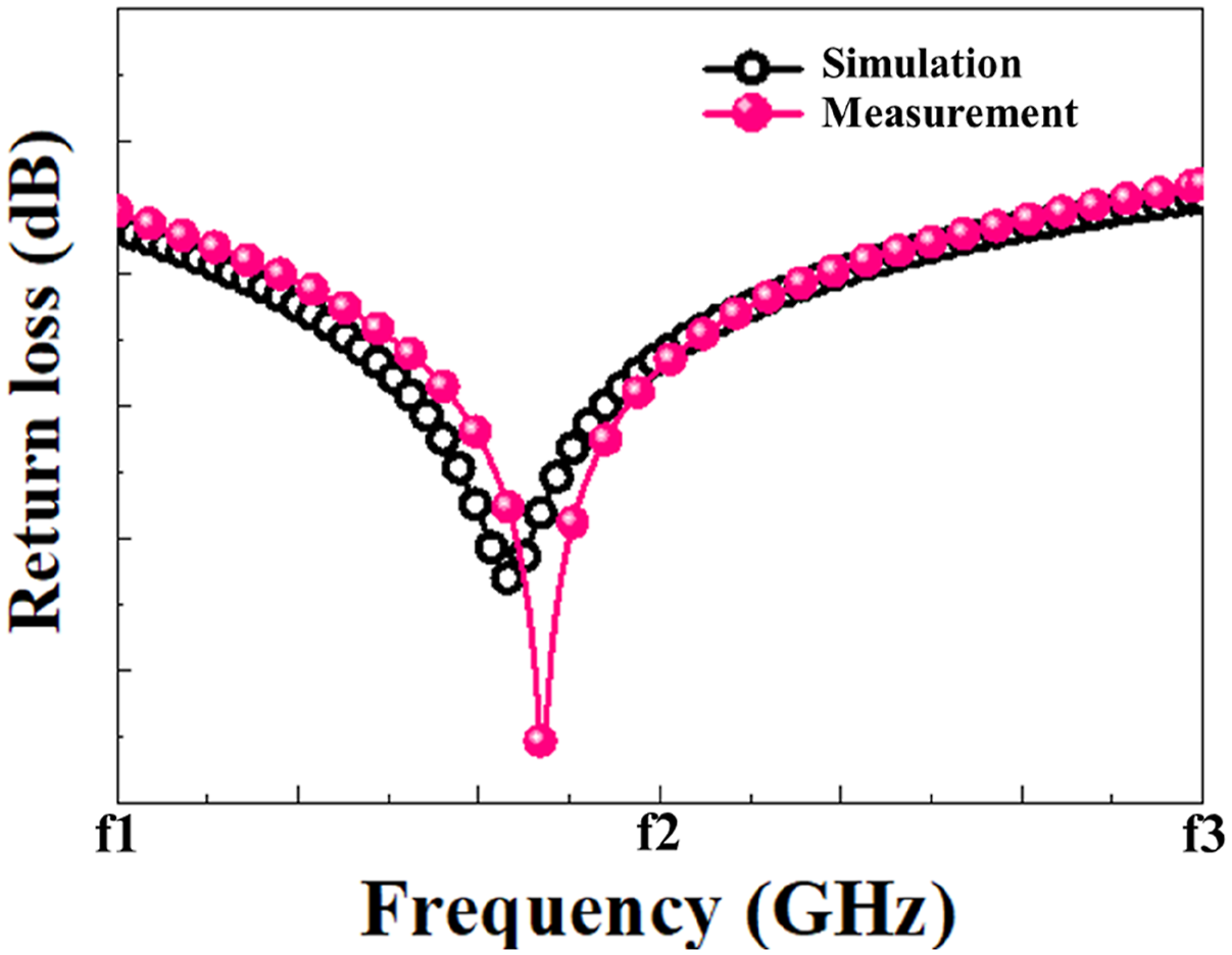
The exceptional radar-absorbing performance of the proposed RAHSS can be attributed to several factors. First, nickel coating on the fabric surface leads to charge accumulation at the interface, generating interface polarization and enhancing the dielectric properties of the face sheet and core cell. 43 Additionally, the internal honeycomb core promotes multiple scattering of incident electromagnetic waves, which enhances energy attenuation and improves overall radar-absorbing performance. Unlike the RAHSS developed in this study, which maintains high absorption efficiency across a target frequency range, the laminate-type RAS proposed by Nam et al. 37 demonstrates a narrower absorption bandwidth. Among laminate designs, the double-slab configuration shows better performance than the single-slab type, although both remain limited in effective bandwidth. These results confirm that the RAHSS offers superior radar-absorbing performance compared to the previously reported laminate-type RAS.
The exceptional radar-absorbing performance of the proposed RAHSS can be attributed to multiple synergistic mechanisms. Nickel coating imparts lossy electromagnetic characteristics to the fabric by increasing the effective permittivity and surface conductivity of the face sheet. This enhances the dielectric and resistive attenuation of incident electromagnetic waves.43,44
This behavior is consistent with previous studies on nickel-coated fabrics, where absorption performance was primarily interpreted in terms of surface resistance modulation and permittivity enhancement. Furthermore, nickel coating introduces multiple metal/dielectric heterointerfaces, including the Ni–glass fabric and Ni–epoxy boundaries, which play a pivotal role in polarization-based attenuation mechanisms.45–48 This phenomenon gives rise to interfacial polarization, thereby enhancing the dielectric loss response of the structure.
As Ni coating exists on the face sheet and honeycomb core, such heterointerface-driven mechanisms are distributed throughout the RAHSS architecture, enabling repeated interactions and cumulative loss effects as wave propagates through the structure.
These heterointerface effects contribute to broadband radar attenuation and efficient energy dissipation, validating the superior performance of the RAHSS compared to conventional laminate-type designs proposed by Nam et al. 37
RCS measurement result
To evaluate the RCS reduction characteristics of the proposed RAHSS, measurements were carried out under transverse-magnetic polarization and far-field conditions in a target frequency range. A specimen of identical dimensions was modeled to simulate the RCS response under the same conditions used in physical measurements. The simulated and measured echo RCS results are shown in Figure 9, alongside the theoretical RCS of a PEC, represented by a copper plate, which serves as a reference. The simulated and measured results demonstrated a significant reduction in RCS compared to the PEC across the entire target frequency range. In particular, both results exhibited notably deeper RCS suppression within specific sub-bands, indicating enhanced stealth capabilities. A close agreement between the simulation and measurement results was further supported by the presence of similar peak points in both datasets, consistent with the observed trends in RL analysis. Minor discrepancies in the peak positions are attributed to slight geometric variations between the fabricated specimen and simulation model. Quasimonostatic RCS reduction of the proposed RAHSS in a target frequency range.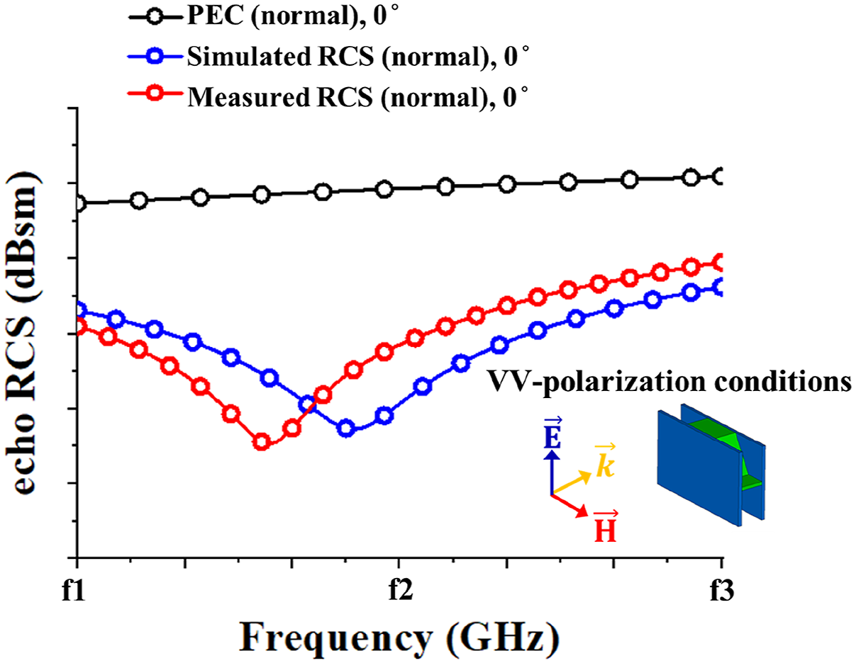
As reported by Kwak et al., 38 a nickel-coated face sheet effectively suppresses specular reflection, thereby reducing the dominant backscattered component governing echo RCS. In addition, nickel coating introduces abundant heterointerfaces between the conductive Ni layer and non-conductive matrix. At these heterogeneous interfaces, charge accumulation and redistribution are induced under incident electromagnetic waves owing to a pronounced mismatch in electrical properties between the two, giving rise to interfacial polarization effect. Consequently, the electromagnetic energy returning toward the radar source further decreases, leading to an additional reduction in echo RCS. 49
Therefore, the proposed RAHSS achieved effective and broadband RCS reduction through a synergistic combination of specular reflection suppression and heterointerface-induced electromagnetic energy dissipation, resulting in stable electromagnetic performance.
Load-bearing capacity
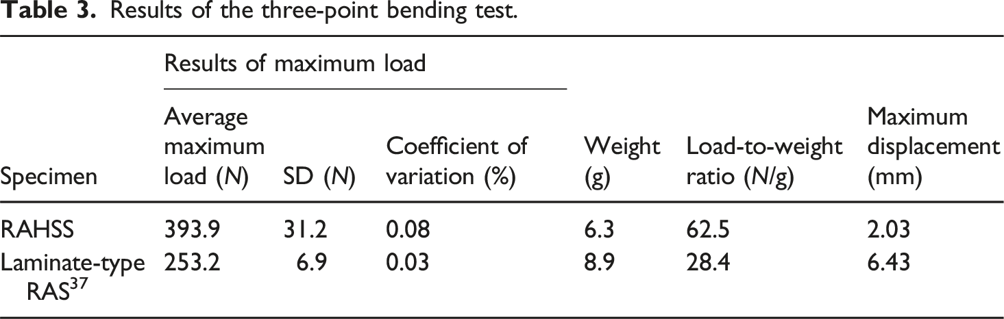
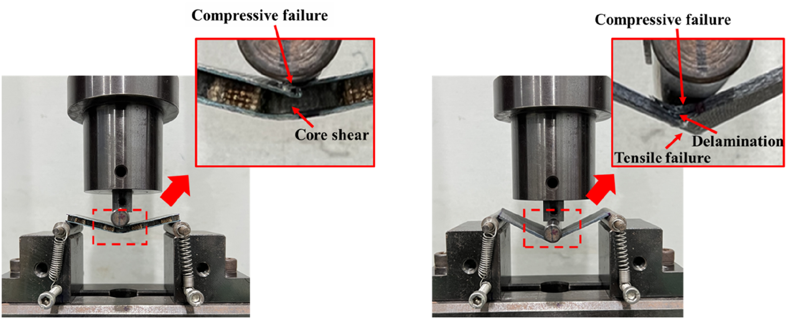
In this study, a three-point bending test was performed to evaluate the bending characteristics of the proposed RAHSS and laminate-type RAS, enabling a comparative analysis. Five specimens of each structure were tested; the load–displacement graph is shown in Figure 10(a). The RAHSS exhibited a steeper slope in the load–displacement curve, indicating superior bending stiffness. This suggests that it possesses excellent radar absorption and a large load-bearing capacity. The averaged test results are shown in Figure 10(b) and Table 3. The standard deviation (SD) and coefficient of variation (CoV) are presented in Table 3 to verify result validity. The average failure loads for the RAHSS and laminate-type RAS were 393.9 and 253.2 N, with maximum displacements of 2.03 and 6.43 mm, respectively. The SD values for the RAHSS and laminate-type RAS were 31.2 and 6.9 N, whereas their CoV values were 8% and 3%, respectively. Unlike the laminate RAS (possessing a simpler integrated structure), the RAHSS consisted of two face sheets and a honeycomb core, making its process more intricate. As load transferred from the face sheet to the core in the RAHSS, slight variations between specimens occurred, leading to its higher CoV than that of the laminate-type RAS. However, the CoV for the RAHSS remained below 10%, indicating reliable and consistent test results. To examine the failure mechanism under bending force, the types of failure experienced by the RAHSS and laminate-type RAS during the three-point bending test were assessed (Figure 11). Owing to its high bending stiffness, the RAHSS exhibited less deflection under bending force, resulting in stress concentration on the upper face sheet in contact with the loading nose. This led to compressive failure at the maximum load point. Damage was observed in the honeycomb core region, directly beneath the upper face sheet where the primary failure occurred, leading to a local failure within the RAHSS (Figure 11(a)). In contrast, the laminate-type RAS exhibited global deflection throughout the specimen when subjected to bending load owing to its lower bending stiffness. Bending stress-induced compressive and tensile failure occurred in the upper and lower face sheets at the maximum load point (Figure 11(b)). Multiple cracks appeared in the central region of the laminate-type RAS, caused by shear load exceeding the interfacial bonding strength between plies, resulting in global failure through the thickness at the loading nose contact point. The load-to-weight ratios for the RAHSS and laminate-type RAS were 62.5 and 28.4 N/g, respectively. This result indicates that the load per unit of weight withstood by the RAHSS is approximately 2.2 times larger than that withstood by the laminate-type RAS. These findings demonstrate that the RAHSS is a viable option for reducing the weight of stealth aircraft structures. Flexural test results: (a) load–displacement graph and (b) comparison of failure load and load-to-weight ratio. Results of the three-point bending test. Typical failure modes observed in the flexural text: (a) RAHSS and (b) laminate-type RAS.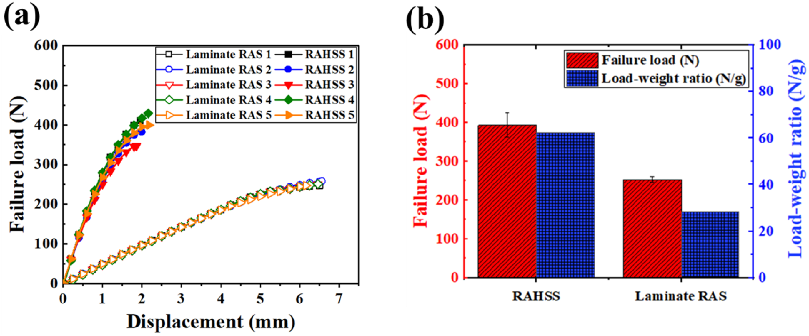
Conclusion
This study introduces a sandwich-structured RAHSS based on a nickel-coated glass fabric, which exhibits enhanced radar-absorbing performance, improved mechanical properties, and reduced weight. The electromagnetic performance of the RAHSS was evaluated through simulation and measurement. The results demonstrated high absorption efficiency across a target frequency range, with the RAHSS outperforming a conventional laminate-type RAS comprising the same materials. The simulated and measured RL results were in close agreement, and echo RCS results confirmed that the structure effectively suppressed backscattered signals through a combination of specular reflection mitigation and polarization loss mechanisms. These findings validate the reliability of the simulation model and effectiveness of the proposed design. The mechanical performance of the proposed RAHSS was assessed through three-point bending tests and compared with that of a laminate-type RAS fabricated from the same constituent materials. The RAHSS exhibited higher resistance to bending-induced failure and deformation, as well as a significantly improved load-bearing efficiency relative to its weight. These results indicate that the sandwich composite architecture provides superior bending performance per unit weight compared to conventional laminate structures. Thus, the RAHSS is an effective and promising design for minimizing the weight of radar-wave-absorbing structures.
Footnotes
Author contributions
Funding
The authors disclosed receipt of the following financial support for the research, authorship, and/or publication of this article: This work was supported by the National Research Foundation of Korea (NRF) grant funded by the Ministry of Science and ICT (RS-2024-00397400). This work was partly supported by the GRRC program of Gyeonggi province (GRRC Aerospace 2023-B05, Fusion Technology Research Center for Advanced Air Mobility).
Declaration of conflicting interests
The authors declared no potential conflicts of interest with respect to the research, authorship, and/or publication of this article.
Data Availability Statement
Data will be made available on request.