






Abstract
As a key lightweight structural material in the aerospace field, aramid paper honeycomb cores are prone to tearing and crushing damage during conventional machining processes. This study investigates the optimization mechanisms of Longitudinal-Torsional Ultrasonic Vibration (LTUV)-assisted cutting on the machinability of this material. Utilizing a self-developed LTUV system and employing a full factorial experimental design combined with analysis of variance, the influences of vibration amplitude, spindle speed, and feed rate on cut-ting forces and surface morphology were systematically quantified. The results indicate that spindle speed (partial η2 = 0.825) and vibration amplitude (partial η2 = 0.801) are the most significant factors affecting cut-ting force. Under the optimal parameter combination (amplitude: 3.2 μm, feed rate: 200 mm/min, spindle speed: 2700 rpm), LTUV reduced the cutting force by approximately 40% compared to conventional machining. Sur-face morphology analysis reveals that LTUV promotes brittle fracture of the material through the periodic tool-workpiece separation effect, leading to significantly improved uniformity of burr size, substantial sup-pression of aramid fluff residue, and effective mitigation of node crushing. However, excessively high amplitude was found to degrade surface quality. This study establishes a process optimization window characterized by “moderate amplitude, low feed rate, and high spindle speed,” and elucidates the mechanism by which LTUV synergistically reduces machining-induced damage through friction reversal and strain rate strengthening effects. The findings provide a reliable process basis for manufacturing high-integrity cores, which is a prerequisite for fabricating high-performance aerospace sandwich structures with superior bonding quality.
Keywords
Introduction
Aramid paper honeycomb core, as a typical lightweight and high-performance composite material, has gained prominence due to its unique hexagonal biomimetic structure, outstanding specific strength, excellent sound insulation and heat insulation properties, as well as its environmentally friendly and sustainable characteristics. It has become an indispensable core structural material in cutting-edge fields such as aerospace, rail transportation, and high-end equipment.1–3 However, precisely because of this porous grid-like structure composed of extremely thin Aramid paper with a typical wall thickness of only 0.05-0.1 mm, it is prone to processing damages such as panel buckling, tearing, and crushing during traditional mechanical processing, resulting in severe surface defects such as burrs, holes, and geometric distortions.4,5 In the manufacturing of sandwich structures, the bonding interface between the face sheet and the honeycomb core is critical for load transfer. Defects such as burrs and fibrous residues generated during core machining act as contaminants, preventing the adhesive from forming a continuous fillet.6,7 Therefore, achieving a defect-free core surface is not just about geometric accuracy, but about ensuring the interfacial strength and fatigue life of the final sandwich composite. Therefore, how to achieve high-quality and low-damage processing of Aramid paper honeycomb core has always been a research hotspot and difficulty in advanced manufacturing fields both at home and abroad.
To address these challenges, scholars both at home and abroad have actively explored various precision and special processing technologies. In terms of optimizing traditional cutting processes, researchers mainly im-prove processing quality by optimizing tool geometric parameters such as rake angle, cutting edge shape and cutting parameters such as rotational speed, feed rate.8–10 For instance, Yuan et al. 11 proposed an ultrasonic vibration processing method with a variable angle cutter disk for milling, comparing the fixed 10-degree angle process in ultrasonic vibration processing with the 1-degree angle process in cutting. The cutting force was significantly reduced by 33.5%, proving the effectiveness of this method in improving surface quality by reducing cutting force; Wang et al. 12 analyzed the inclined ultrasonic cutting process using a disc cutter and conducted cutting experiments with different inclination angles. Due to the inclination angle, the residual height of the honeycomb core was much greater than the height caused by the leading angle, demonstrating that the residual height of the honeycomb core was much greater than that caused by the leading angle, and the determination of the inclination angle should take into account the actual processing requirements of the remaining height and the processing quality of the cell wall. However, since TC is essentially a “compression shear” process where the tool and the workpiece are in continuous contact, it is difficult to avoid continuous loading on the honeycomb wall, and there is a bottleneck in its improvement effect on the inherent fragility of the honeycomb core structure. After processing, problems such as fiber pulling, residue of floccule, and structural collapse often occur.
In this context, the ultrasonic vibration-assisted processing technology, as an advanced manufacturing technology developed to address the cutting damage of thin-walled, weakly rigid, and easily deformed materials and to improve surface quality and processing accuracy, has demonstrated unique advantages in the low-damage precision manufacturing of porous thin-walled structures, providing a feasible technical approach for the high-quality processing of the research object in this paper. 13 This technology combines the conventional motion of the cutting tool with high-frequency, low-amplitude vibrations typically above 20 kHz, causing periodic contact and separation between the tool and the workpiece, thereby transforming continuous cutting into intermittent pulse cutting. This unique processing mode has been proven to have significant advantages in reducing cutting forces, improving chip morphology, enhancing surface integrity, and prolonging the tool’s service life.14,15 Particularly in the field of composite material processing, ultrasonic vibration can effectively reduce cutting forces, promote brittle fracture of the material, and minimize burrs and tears caused by plastic deformation. 16 For example, in the processing of carbon fiber compo-sites, ultrasonic vibration-assisted cutting significantly reduces delamination defects; when processing brittle materials such as ceramics and glass similar to honeycomb cores, it also exhibits excellent surface quality.17–19
Previously, the ultrasonic vibration modes applied to composite materials such as paper honeycomb cores mainly included ultrasonic longitudinal vibration and ultrasonic elliptical vibration. Hu et al. 20 explored the possibility of enhancing the dry machinability of TC4 titanium alloy by applying the newly proposed longitudinal extended hybrid ultrasonic vibration-assisted milling technology. This method effectively regulated the intermittent cutting behavior between the tool and the workpiece material, reducing the surface roughness by 46.7% and the cutting force by 43.2%. Zhang et al. 21 designed and manufactured a large-amplitude longitudinal ultrasonic vibration-assisted milling tool holder, enabling efficient and high-quality milling of carbon fiber-reinforced polyether ketone at a feed rate of 700 mm/min. Duan et al. 22 investigated the effects of longitudinal ultrasonic vibration on the grinding forces and surface quality of 2.5D C-f/SiC composites during UASG and UAEG through single-factor experiments, revealing the grinding mechanisms under the two processing methods. The experimental results showed that longitudinal vibration in both processing methods had different influences on grinding forces and surface roughness. After applying longitudinal vibration, the reduction in grinding force was the greatest during the side grinding process. However, the reduction in surface roughness was the greatest during the final grinding process, reaching 35.6%. For the removal of each phase of 2.5D C-f/SiC composites, applying ultrasonic vibration in both processing methods could reduce brittle fracture, fiber debonding, and matrix fracture. Qiu et al. achieved significant reduction in thermal and mechanical damage by using ultrasonic vibration-assisted milling for aluminum honeycomb laminates. At a feeding rate of 60 mm/min, UVAM reduced the temperature entering the aluminum honeycomb core by approximately 29%, and the core material tear damage was reduced by 25%. At a lower feeding rate of 40 mm/min, the temperature was further reduced by 31%, confirming that optimizing the parameters can enhance the process efficiency. 23 On the other hand, UEVC shows great potential in processing metal-based composites such as Al-Si alloys due to the elliptical trajectory movement of the tool tip, which can generate a friction reverse effect, being more conducive to chip removal and reducing the average cutting force.24–26 For example, Yin et al. 27 based on the mathematical model of the workpiece surface morphology under inclined ultrasonic elliptical vibration cutting, and considering the tip trajectory and material removal mechanism, studied the changes in the workpiece surface morphology under different tool inclination angles θ, and found that within a certain range of inclination θ, the surface residual height could be significantly reduced, compared to ordinary cutting with ultrasonic elliptical vibration. Su et al. 28 used hard alloy tools for ultrasonic elliptical vibration cutting, conducted comparative experiments involving whether or not ultrasonic elliptical vibration was included in the cutting process, to evaluate tool wear, chip formation, surface integrity, and the evolution of sub-surface microstructure, and the results showed that UEVC significantly inhibited tool wear and achieved the formation of defect-free surfaces. Chen et al. mentioned that the ultrasonic elliptical vibration cutting technology applies ultrasonic vibrations to the cutting tool, intermittently separating it from the workpiece. This innovative method reduces cutting force and improves the quality of the workpiece surface processing. The application of ultrasonic elliptical vibration cutting technology is summarized, with a particular emphasis on extending the tool life, improving surface integrity, and preparing functional surfaces during the cutting of difficult-to-cut materials. 29
However, although the ultrasonic vibration processing technology has made significant progress, the potential and unique mechanism of a combined mode of longitudinal and torsional vibration -LTUV - in the processing of aramid paper honeycomb cores have not yet been systematically revealed. Compared with the single LUV or UEVC, LTUV can, through the design of spiral slits on the amplitude rod, excite the coupling vibration of the tool in the axial and tangential directions, forming a complex spatial three-dimensional motion trajectory. 30 This trajectory is expected to achieve extremely low damage processing of the honeycomb wall through a stronger “tool-workpiece” periodic separation effect and more efficient chip removal and chip discharging ability. Currently, research on LTUV mainly focuses on homogeneous metal materials, while for its application in anisotropic, porous and brittle aramid paper honeycomb materials, the influence laws of vibration parameters such as amplitude and phase difference on the material removal mechanism, dynamic characteristics of cutting force, and surface defects such as burrs, crushing, and flocculent substances suppression effect are lacking in in-depth systematic studies.31–33 Especially, the interaction between vibration parameters and cutting parameters on how it affects the morphology quality of different structural feature areas such as nodes, single-layer walls, and double-layer walls remains a research content that needs to be continuously explored. This lack of understanding limits the in-depth understanding of the complex physical process of LTUV processing honeycomb cores and also hinders the precise optimization and wide application of this advanced processing parameter. This paper supplements the representative research achievements in the field of ultrasonic processing of aramid paper honeycomb cores over the past 5 years. A comparative analysis is conducted from the aspects of the reduction in cutting force of the core material and the improvement in surface quality. The results show that under low-amplitude processing conditions, the longitudinal-twisting composite ultrasonic vibration method adopted in this study achieved a more significant reduction in cutting force and a better control effect on burrs, fully verifying the unique technical advantages of the longitudinal-twisting combined vibration compared to single vibration type ultrasonic processing.
In view of this, this paper aims to systematically and deeply investigate the influence mechanism of longitudinal torsional ultrasonic vibration-assisted cutting on the processing performance and surface integrity of aramid paper honeycomb cores. This study designed and built an independently developed longitudinal torsional composite ultrasonic vibration processing system, which was integrated onto a drilling and milling machine platform. The research content mainly includes: (1) Through full-factor experimental design, systematically quantify the main effects and interaction effects of three key process parameters (amplitude, spindle speed, and feed rate) on the axial cutting force (Fz), and use variance analysis to determine their significance levels; (2) Based on single-factor exploratory experiments, reveal the nonlinear influence patterns of each parameter on the cutting force, and use main effect diagrams and interaction diagrams to deeply analyze the coupling mechanism between the parameters; (3) Utilizing high-resolution microscopes, precisely observe and compare the surface morphology evolution patterns of key areas such as honeycomb core nodes, single-layer walls, and double-layer walls under traditional cutting and different LTUV parameters, and particularly clarify the inhibition mechanism of longitudinal torsional ultrasonic vibration on defects such as burrs, crushing deformation, and filamentous residue.
This research through a combination of theoretical and experimental methods, not only provides a solid basis for process optimization and a theoretical explanation for the longitudinal torsional ultrasonic vibration-assisted cutting of aramid paper honeycomb cores, but also deepens the understanding of the collaborative effects of multiple parameters in the vibration processing of composite materials. It also lays an important theoretical and practical foundation for the future development of precise and low-damage manufacturing technologies for new-generation high-performance honeycomb structural materials.
Theory
The working principle of the torsional-combined ultrasonic processing system
The longitudinal-torsional composite ultrasonic vibration, as an advanced ultrasonic vibration-assisted processing mode, is unique in that it enables the tool to generate both axial and tangential coupled vibrations simultaneously. The core component of this technology is the custom-designed longitudinal-torsional composite ultrasonic vibration system, which consists of an ultrasonic generator and an ultrasonic vibration unit. The ultrasonic vibration unit, as the final execution component of the system, integrates an ultrasonic transducer, a specially designed amplitude rod, and the tool component. Its basic working principle as shown in Figure 1 (a): the high-frequency electrical oscillation generated by the ultrasonic generator is converted by the transducer into high-frequency, low-amplitude mechanical vibrations. This pure longitudinal vibration is then transmitted through the amplitude rod. The key to achieving longitudinaltorsional coupling vibration lies in the spiral slot structure designed on the amplitude rod. When the pure longitudinal wave passes through this slot-amplitude rod, the spiral slot causes a modal conversion effect. Due to impedance mismatch and the asymmetric boundary conditions produced by the slot, the incident longitudinal wave will partially convert into torsional waves, thereby generating longitudinal-torsional composite vibration at the tool tip. Therefore, any point on the cutting edge will exhibit a complex two-dimensional vibration trajectory: one is the axial displacement along the tool bar direction, and the other is the radial displacement perpendicular to the cutting direction. Compared with the traditional cutting mode where the tool and the workpiece are in continuous contact and endure continuous compressive-shear stress, LTUV introduces a high-frequency periodic contact separation between the tool and the workpiece. This intermittent cutting mechanism effectively reduces the average cutting force and thermal load. Moreover, the unique spatial motion trajectory of the tool tip enhances the chip breaking and chip removal capability, and changes the friction state between the tool and the workpiece, thereby significantly suppressing defects such as burrs and tearing during the processing, and improving the processing quality. Meanwhile, Figure 1(b) also presents the typical structural features of the aramid paper honeycomb core material, including the alternating distribution of singlewall and double-wall cell walls, thin-walled flexible structure, and the connection form of honeycomb nodes. Schematic diagram: (a) Process Diagram of Ultrasonic Assisted Cutting of Aramid Paper Honeycomb Cores with Longitudinal-Torsional Composite Vibration, (b) Structural diagram of aramid paper honeycomb core material.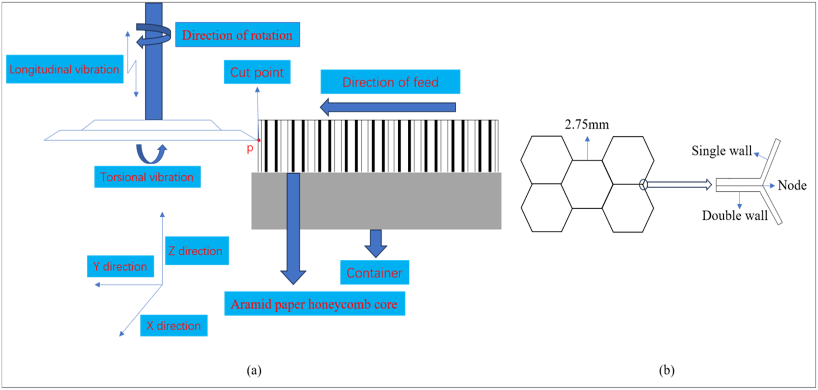
Analysis of tool movement
Tool motion trajectory model
In the longitudinal-torsional composite ultrasonic vibration system, the motion at the tip of the cutting tool can be decomposed into two mutually perpendicular components: the longitudinal vibration along the tool axis direction and the torsional vibration rotating around the tool axis. Moreover, the motion trajectory of any point on the tool can be derived from formulas (1), (2), and (3). 34



The spatial trajectory of any point on the three-position combined cutting tool is described as follows: r is the vertical distance from this point to the rotation axis; n is the spindle speed; A is the ultrasonic amplitude, which controls the radial and axial vibration displacements; f is the ultrasonic frequency; φ is the longitudinal torsional ultrasonic phase difference; vf is the feed rate of the workpiece relative to the tool; t is the cutting time. The coupling of these variables leads to the motion trajectory of the point being described as a “rotation - feed - longitudinal torsional ultrasonic” compound motion. The torsional vibration component is reflected in the phase modulation term A∙ sin (2πft)/r in formulas (1) and (2), which causes high-frequency oscillation of the tool’s angular position. This term is combined with the axial vibration Sz, resulting in a complex three-dimensional elliptical-spiral path for the tool tip trajectory. As shown in Figure 2, this unique trajectory is the fundamental reason for the intermittent cutting behavior, friction reverse effect, and enhanced chip removal ability of LTUV, and these characteristics jointly contribute to its excellent performance when processing brittle materials such as aramid paper honeycomb cores. Figure 2a illustrates the spatial helical motion trajectory of the LTUV tool, clearly presenting the entire process from the initial engagement to stable cutting and then to the cutting out. The arrow on the curve indicates the rotation direction of the tool. Figure 2a adds a local magnification view next to the main trajectory curve, which is used to highlight the entry and exit positions of the elliptical helical motion, facilitating an intuitive understanding of the movement pattern of the tool within the cutting area. Figure 2b shows the corresponding torsional displacement-time curve, clearly providing the frequency, period and amplitude of the torsional vibration, and intuitively reflecting the high-frequency dynamic vibration characteristics of the tool. Vibration Trajectory and Time History Curves of Torsional Displacement: (a) Space elliptical spiral trajectory, (b) Variation of torsional displacement with time.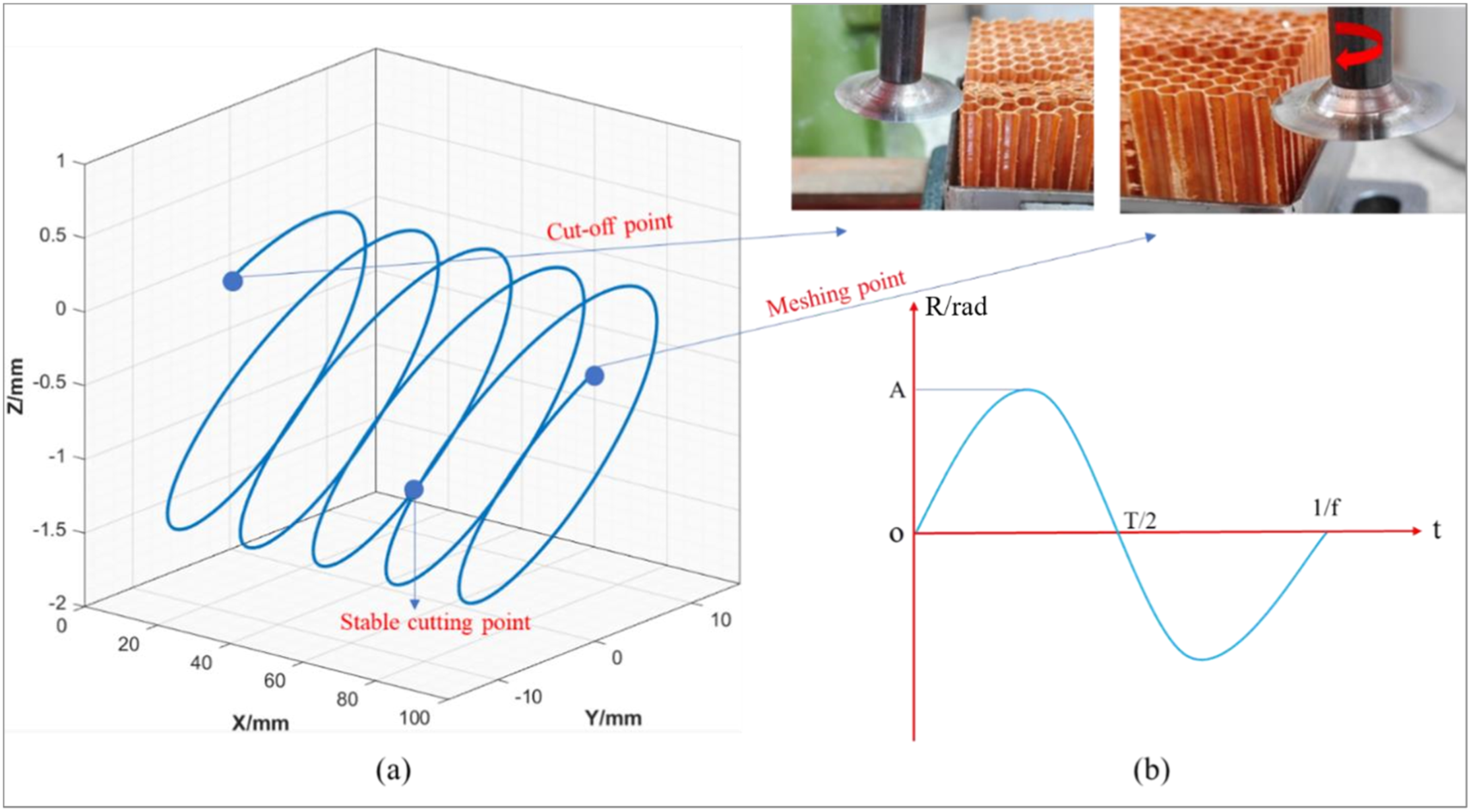
Cutting separation effect
The most distinctive feature of LTUV processing is the periodic separation between the tool and the workpiece. In conventional cutting, a tight contact is formed between the chip and the rake face of the tool, resulting in a continuous action of cutting force on the workpiece, which is prone to causing the collapse and tearing of the aluminum honeycomb core. However, in LTUV processing, due to the high-frequency vibration of the tool, when the instantaneous speed direction of the tool is opposite to the cutting direction, the tool will instantly separate from the workpiece or the chip. This separation effect brings the following key impacts: (1) Reduced cutting force: Due to the shortened contact time between the tool and the workpiece, the average cutting force significantly decreases. This effectively reduces the compression force exerted by the tool on the honeycomb core wall, preventing the buckling and tearing of the thinwalled structure. (2) Changed friction state: The separation effect alters the friction state between the rake face of the tool and the chip. At the moment of separation, the friction force direction between the chip and the tool reverses, which helps the chip to be smoothly discharged and reduces the secondary scratches of the machined surface by the chip. (3) Improved heat dissipation: The separation process provides a brief cooling gap in the cutting zone, facilitating heat dissipation and reducing the temperature in the processing area, thereby minimizing thermal damage.
Material removal mechanism
At the material removal mechanism level, previous ultrasonic processing studies have mostly focused on dense metals or single brittle materials, mainly adopting high-frequency impact crushing or abrasive scraping as the core removal mechanism.35–37 However, this study targets honeycomb core materials, a type of porous lightweight sandwich structure, and its removal mechanism shows significant differences: in the honeycomb cell wall area, the main mechanism is brittle layer cracking caused by vibration, with high-frequency impact leading to the peeling of thin-walled fiber layers along the interface; in the node area, it is characterized by the combined effect of shear fracture at high strain rates and local microcracks, avoiding the large deformation and tearing damage at the nodes in traditional cutting. This wall-node differential removal mechanism has not been systematically reported in previous ultrasonic processing studies and is the core innovation point of this research. Compared with existing ultrasonic cutting studies: traditional longitudinal ultrasonic vibration cutting mainly reduces the average cutting force through the separation effect, while this study adopts a longitudinal-rotational compound ultrasonic vibration, which, in addition to the separation effect, also introduces a circumferential shear component. This not only further reduces the contact area between the tool and the workpiece but also promotes the directional peeling of the fiber layer through torsional shear, making the material removal more efficient and causing less damage.
Experiment design
Experimental facility
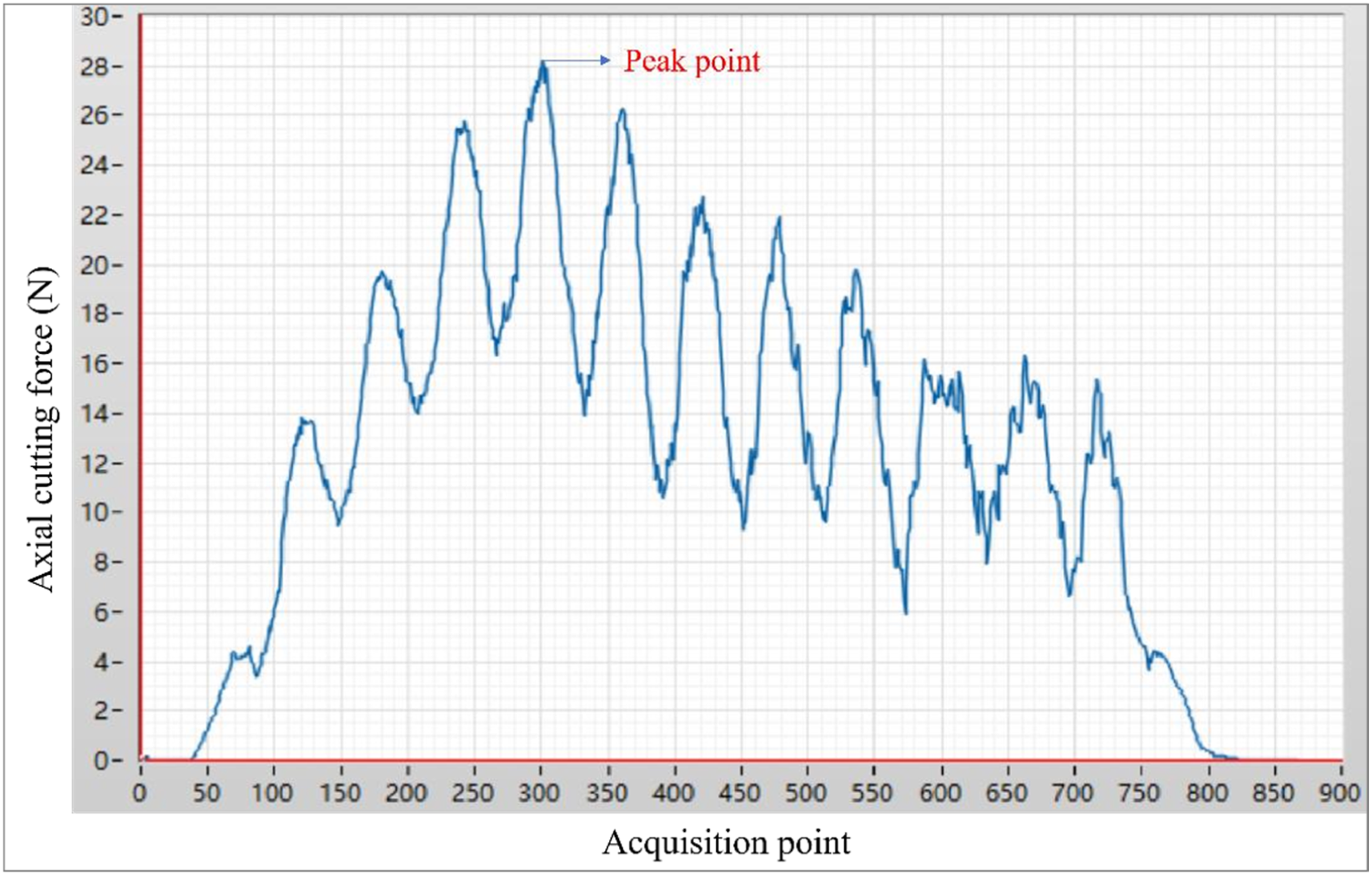
The experimental platform was constructed based on a drilling and milling machine, which provided precise control for the translation and rotation movements of the cutting tools. The core of this study was a set of independently developed longitudinal-torsional composite ultrasonic vibration-assisted processing device, which was installed on the spindle of the machine, as shown in Figure 3. This system operates at a resonant frequency of 20 kHz, aiming to superimpose high-frequency vibrations onto the conventional cutting motion for ultrasonic processing. Considering the inherent structural fragility of the aramid paper honeycomb core, a specialized method for holding the workpiece was adopted to ensure positional stability during the processing and to suppress vibrations. Before cutting, a quantitative amount of paraffin wax was placed in a custom mold and heated until complete liquefaction. Then, the honeycomb core sample was carefully immersed in the molten paraffin wax to ensure complete penetration. Subsequently, the entire component was cooled at ambient temperature until the paraffin wax solidified, effectively embedding the honeycomb core into the supporting substrate. Then, the entire component was firmly clamped onto the machine worktable using standard vise jaws. To accurately measure the cutting force, a three-directional dynamometer was placed directly beneath the workpiece fixture. The three-dimensional force sensors used in the experiment were selected from the DYDW series multi-dimensional force sensors produced by Beting Ocean Sensor System Engineering. These sensors have a maximum sampling frequency of up to 10 kHz, which can meet the requirements for collecting macroscopic cutting force signals in this study. All the sensors and the accompanying acquisition equipment were factory-calibrated by the manufacturer according to industrial-grade measurement standards. The calibration process strictly followed the provisions in the product manual, effectively ensuring the accuracy and reliability of the measurement data. The dynamometer was connected to a force amplifier and a data acquisition system linked to a computer, enabling real-time recording of the cutting force (Fx, Fy, Fz) throughout the processing. This experiment focused on the cutting force in the Fz direction. In order to further characterize the variation characteristics of the longitudinal-torsional composite ultrasonic vibration cutting force, the dynamometer collected real-time data of the axial cutting force Fz at a high sampling frequency during the stable cutting stage, and the curve of the cutting force variation was extracted from it. Meanwhile, the mean force and peak force were calculated from the dynamic force data. In this study, the axial cutting force index adopted was the mean force, and all characteristic values were verified by three repeated experiments to ensure the reliability of the data. Figure 4 shows the cutting force curve versus sampling points under the optimal parameter combination in longitudinal-torsional ultrasonic cutting. Limited by the response frequency of the dynamometer, this curve only reflects the macroscopic trend of cutting force and cannot characterize the high-frequency dynamic characteristics of ultrasonic vibration. The force analysis in this paper is based on the macroscopic average cutting force and the overall load fluctuation pattern. The relevant conclusions can effectively support the analysis of the cutting mechanism. Experimental setup diagram for longitudinal torsional combined ultrasonic vibration-assisted cutting. The curve of cutting force in longitudinal torsion ultrasonic machining varying with the acquisition point under the optimal parameter combination.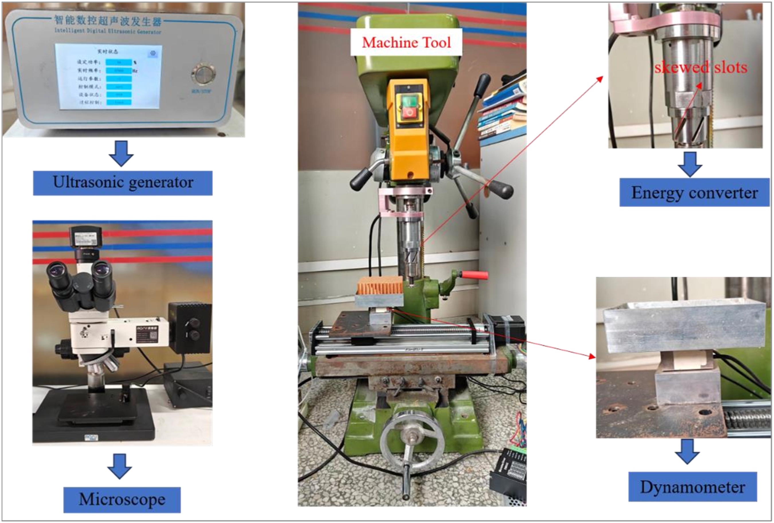
Experimental materials and conditions
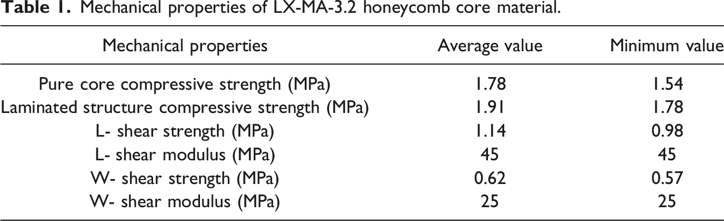
The workpiece material used in this study is the LX-MA-3.2 type hexagonal aramid paper honeycomb core. The sample size is 100 × 60 × 40 mm, the edge length of the honeycomb is 2.75 mm, the wall thickness is 0.1 mm, and the density is 48 kg/m3. As shown in Figure 5, the cutting tool was a high-speed steel disc-shaped tool. The geometric parameters of the core were determined based on the experimental design and the actual specifications of the tool: the wedge angle was 8°, the tool was of a disc structure, and it was suitable for the horizontal cutting scenario of honeycomb core materials. The key mechanical properties of this material are detailed in Table 1. To focus on the influence of the main process parameters, the cutting depth for all tests is uniformly set at 2 mm. This parameter was determined based on the typical application thickness of aramid paper honeycomb core materials in aerospace sandwich structures, and was comprehensively determined by considering the actual cutting capacity of the experimental equipment. Preliminary exploratory experiments compared and tested three cutting depths of 1 mm, 2 mm, and 3 mm. The results showed that at the cutting depth of 2 mm, the cutting force was within the stable working range of the equipment, and the defects such as burrs and collapse on the processed surface of the honeycomb core material were obvious and representative, which could effectively characterize the processing effect of longitudinal torsional composite ultrasonic vibrationassisted cutting of aramid paper honeycomb. This is consistent with the research results of Zhang et al. on the cutting depth of honeycomb-like lightweight sandwich structures.
34
To systematically study the effects of ultrasonic vibration and conventional cutting parameters, a full-factorial experimental design with three factors and four levels was adopted. The selected independent variables are ultrasonic amplitude, spindle speed, and feed rate. The values of each parameter level were obtained from preliminary single-factor exploration experiments and recommendations in the machine tool technical manual to ensure a comprehensive coverage of the actual processing window. The dependent variable is the axial force Fz. This design includes 4 × 4 × 4 = 64 experimental runs. After each cutting test, the processing surface morphology of the honeycomb core and the wear condition of the tool were observed using the L100/100BD industrial inspection microscope and the XDS/10A high-definition video microscope. Experimental material sample and physical diagram of cutting tool. Mechanical properties of LX-MA-3.2 honeycomb core material.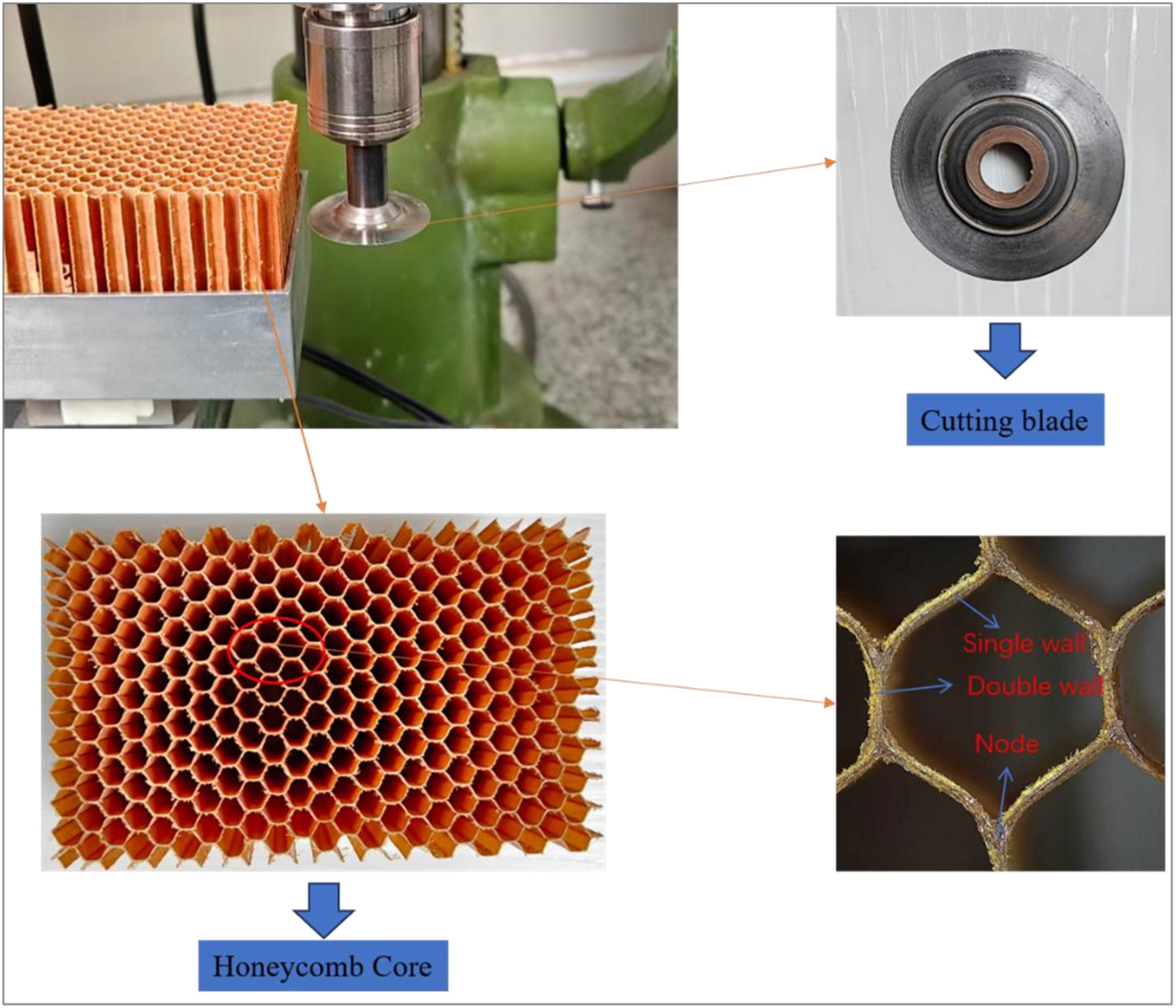
Full-factorial experimental level combinations.
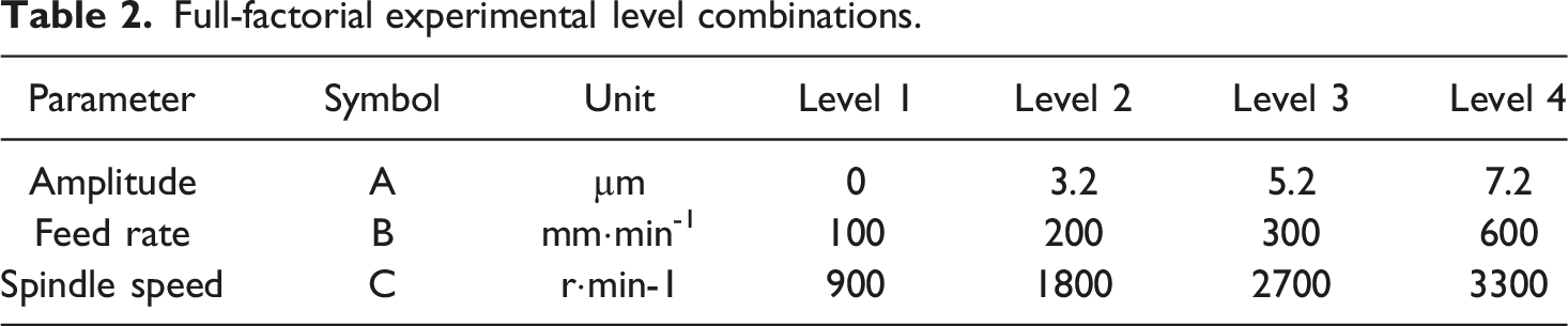
This full-factor design consists of 3 factors, each with 4 levels, thus generating 64 unique experimental conditions.
To accurately estimate experimental errors and enhance the power of statistical tests, 3 repetitions of each experimental condition were conducted. Therefore, the total number of experiments was 192. The running sequence of all experiments was carried out using a completely randomized method. Randomization is a key principle in experimental design, aiming to eliminate systematic interference from “latent variables” such as tool progressive wear and environmental fluctuations on the experimental results, ensuring that the observed differences truly result from changes in process parameters. This experiment used axial cutting force Fz as the main response variable to quantitatively evaluate the processing effect. Cutting force data was collected through a three-directional force measuring instrument system. The force signal during the stable cutting process was recorded for each experiment, and the average value was taken as the Fz value for that experiment.
Results and discussion
Single-factor exploratory experiment
Before the full-factor experiment, a series of single-factor exploration experiments were conducted. The core purpose of the single-factor exploratory experiment is to initially identify the trend of the influence of rotational speed on the processing results. Therefore, multiple gradient rotational speed levels were set to cover a wider range of operating conditions, providing a basis for the parameter range selection of the subsequent full-factor experiment. The results of the single-factor experiment show that under the 500 r/min condition, the experimental data fluctuate significantly, the signal-to-noise ratio is extremely low, and the process effects such as cutting force stability and surface integrity are far worse than those at rotational speeds of 900 r/min and above, lacking practical engineering application value. In these experiments, the control variable method was strictly applied. When studying the influence of one factor, the other two factors were maintained at their recommended median values. To ensure reliability and statistical significance, each experimental condition was repeated three times. The final result of each condition was the arithmetic mean of the three measurements, and the standard deviation was represented as error bars in the resulting graph.
Explore the influence of each parameter on the magnitude of cutting force.
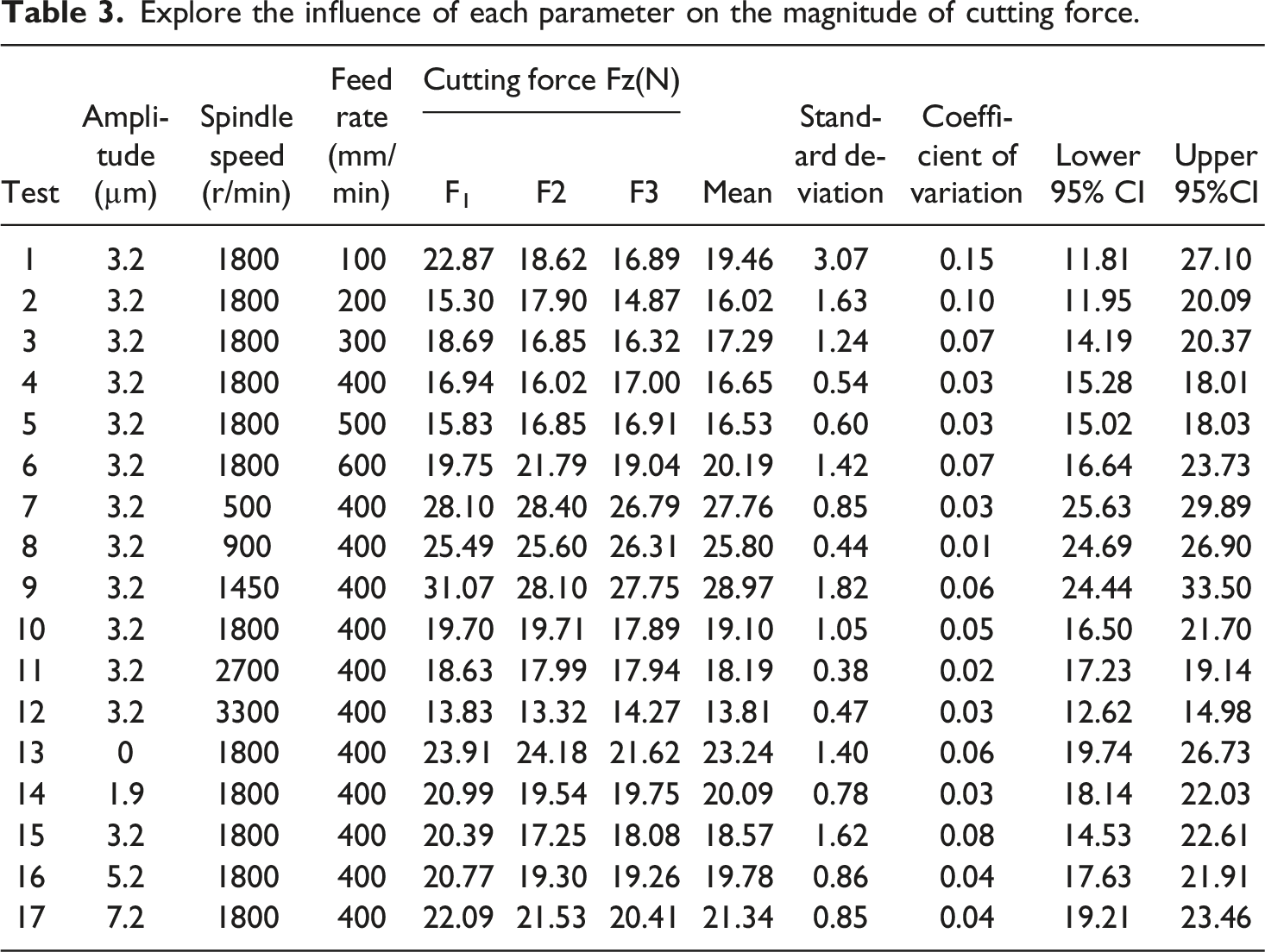
As shown in Figure 6, the amplitude of the cutting force shows a “sharp decline - gradual increase - saturation” three-stage characteristic, with the minimum value occurring at 3.2 μm. From the perspective of the cutting mechanism, this nonlinear relationship can be explained by the competitive mechanism between the separation effect of longitudinal torsional vibration and the cumulative effect of impact: In the low amplitude range: The combined longitudinal torsional vibration causes the tool and the workpiece to separate periodically, significantly reducing the instantaneous uncut chip thickness and the friction contact area. The separation effect dominates, so the cutting force decreases sharply with the increase in amplitude. In the medium amplitude range: When the amplitude exceeds 3.2 μm, the marginal decelerating effect of the vibration separation effect gradually saturates, while the plastic deformation of the material caused by high-frequency impact and the repeated compression and friction loss between the tool and the workpiece begin to increase. The augmenting effect gradually exceeds the decelerating effect, resulting in a recovery of the cutting force with the increase in amplitude. In the high amplitude range: As the amplitude further increases, the tool’s movement trajectory and the degree of material deformation have approached the limit. The competition between the separation effect and the impact effect reaches a dynamic balance, and the cutting force no longer significantly changes with the amplitude, entering the saturation stage. Therefore, the amplitude levels are set as 0 μm (Traditional processing benchmark), 3.2 μm (Optimal vibration reduction point), 5.2 μm (Over-amplitude range), and 7.2 μm (Device upper limit), forming a complete comparison chain from benchmark, optimal, transition to limit, to deeply analyze the process window of amplitude. The influence of feed rate on cutting force shows a “V” type non-linear relationship of first decreasing and then increasing. Based on single-factor experiments, when the feed rate increases from 100 mm/min to 200 mm/min, the cutting force Fz drops to the lowest 16.02 N; beyond this point, the force value begins to rise with the increase of feed rate. To fully capture this change pattern, this study selects four levels: 100 mm/min (Lower limit), 200 mm/min (Minimum force value), 300 mm/min (Force value recovery zone), and 600 mm/min (Upper limit), in order to systematically reveal the process characteristics of the feed rate in the entire variation ran. The variation pattern of cutting force with respect to various experimental parameters.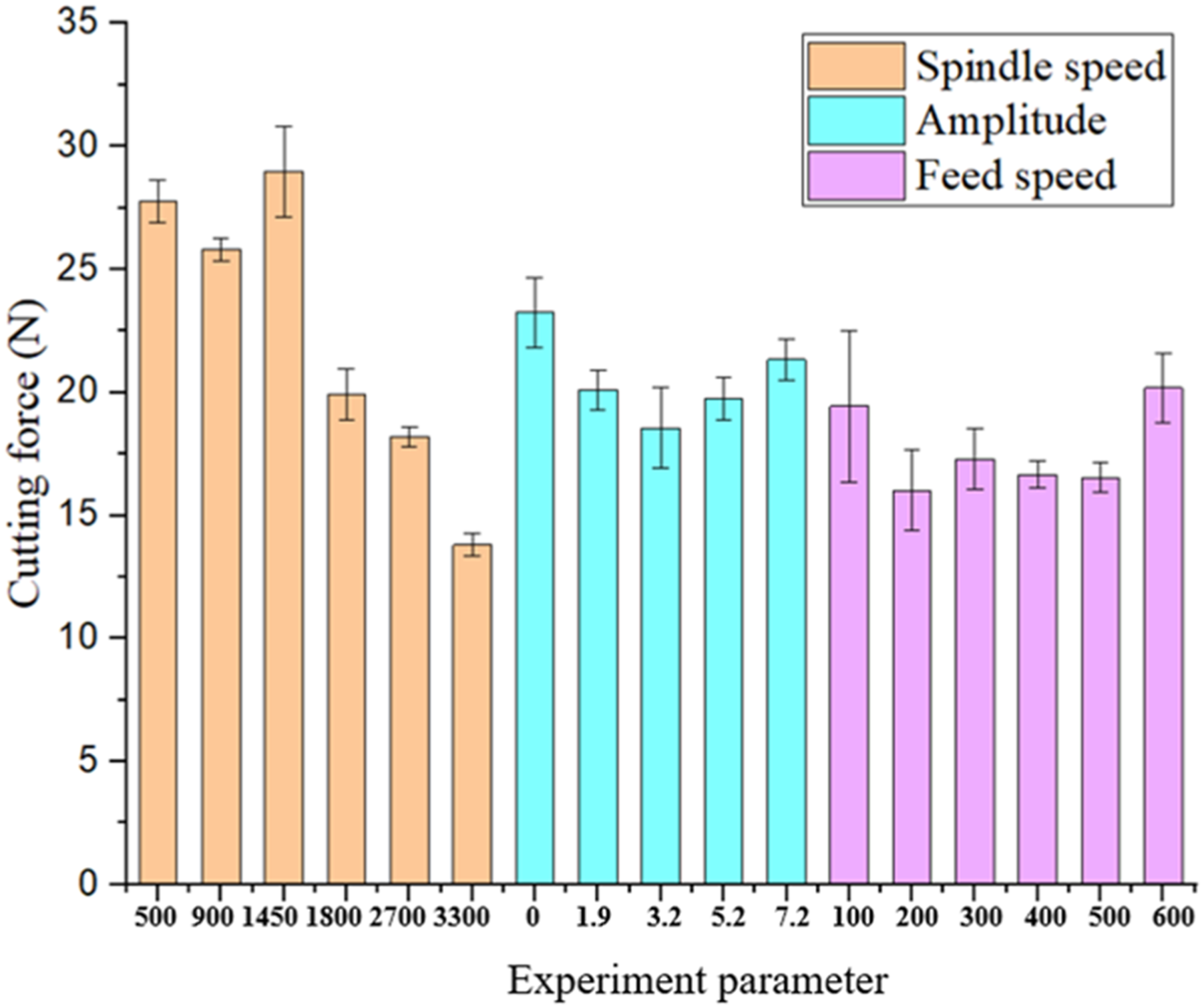
According to the research results of the influence law of spindle speed on cutting force in the single-factor exploration experiment, to systematically investigate the influence of this parameter and effectively support the full-factor experimental design, the spindle speed levels are selected as follows: under the condition of fixed amplitude of 3.2 μm and feed rate of 400 mm/min, the cutting force generally decreases with the increase of spindle speed (From 900 r/min to 3300 r/min). To cover the key variation range, the levels are set as C1 = 900 r/min (Low speed benchmark), C2 = 1800 r/min (Medium speed sensitive point), C3 = 2700 r/min (High speed reduction zone), and C4 = 3300 r/min (Speed upper limit). This level combination can effectively capture the influence characteristics of the spindle speed in different low, medium, and high intervals on the cutting force, providing a complete parameter comparison chain for subsequent process optimization.
The results of the significance difference test
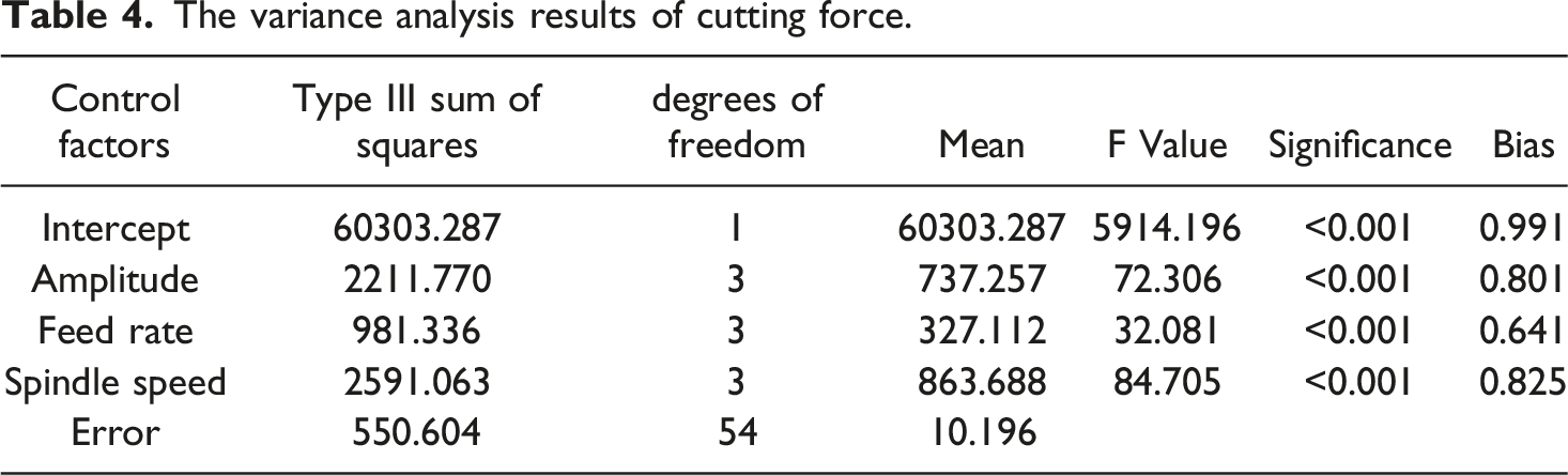
Analysis of variance results for cutting force
The variance analysis results of cutting force.
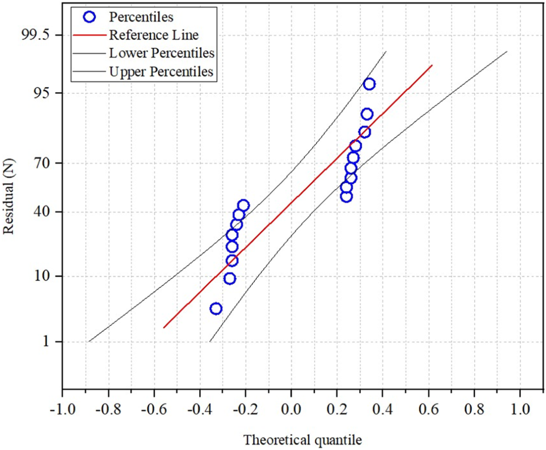
To verify the reliability and applicability of the established model, this paper plots scatter diagrams of residuals versus fitted values, as shown in Figures 7 and 8. From the distribution of residuals, it can be seen that they are randomly distributed on both sides of the Y = 0 reference line, without any obvious trend or heteroscedasticity phenomenon. This satisfies the homoscedasticity and independence assumptions of the model, indicating that the model fits well. At the same time, a 95% confidence interval is added to the response surface prediction graph to quantify the uncertainty range of the prediction results, enhancing the rigor and reference value of the model prediction. Residual-fitted value scatter plot of the cutting force prediction model. The response surface plot of cutting force with a 95% confidence interval.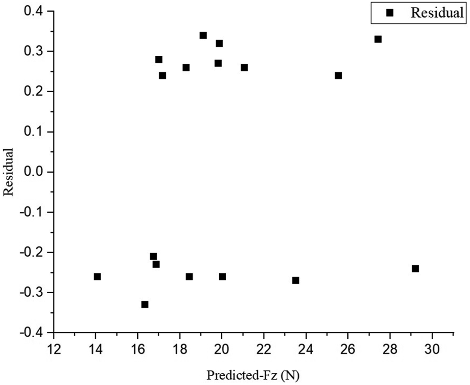
Pairwise comparison of cutting forces at different amplitude levels.
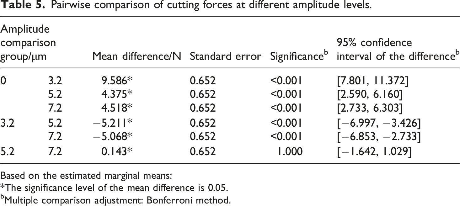
Based on the estimated marginal means:
*The significance level of the mean difference is 0.05.
bMultiple comparison adjustment: Bonferroni method.
Pairwise comparison of cutting forces at different spindle speed levels.
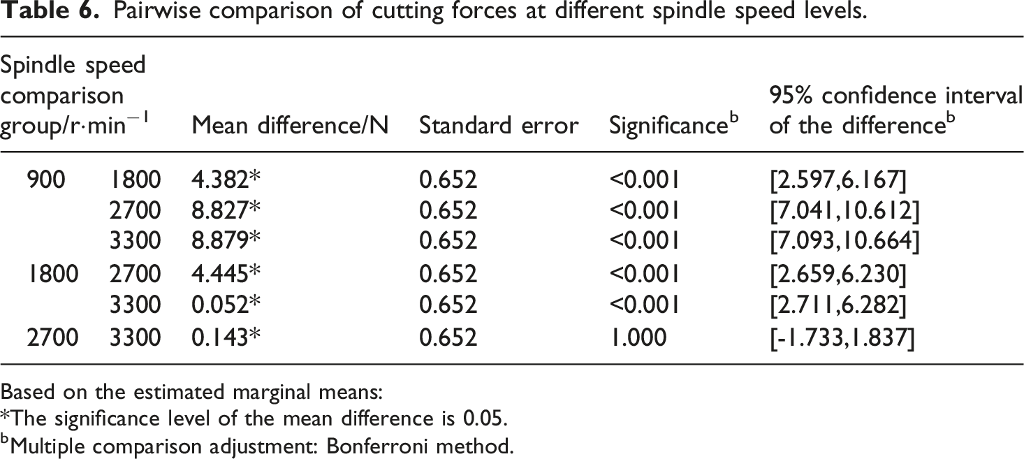
Based on the estimated marginal means:
*The significance level of the mean difference is 0.05.
bMultiple comparison adjustment: Bonferroni method.
Pairwise comparison of cutting forces at different feed rate levels.
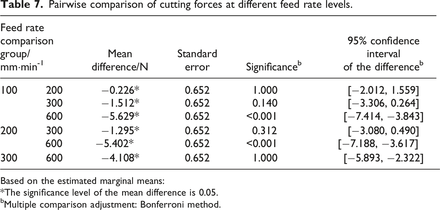
Based on the estimated marginal means:
*The significance level of the mean difference is 0.05.
bMultiple comparison adjustment: Bonferroni method.
Analysis of experimental results
Based on the results of the orthogonal experimental design, as shown in Figure 9, the main effect analysis revealed the independent influence of each process parameter on the cutting force. Figure 9 (a) indicates that the spindle speed has a significant impact on the magnitude of the cutting force. From Figure 9 (b), it can be concluded that the amplitude has a non-linear effect on the cutting force: the cutting force reaches its minimum value around an amplitude of 3 μm, and then increases again as the amplitude increases, indicating a specific amplitude range that optimizes the cutting force. Secondly, Figure 9 (c) shows that the feed rate exhibits a clear linear positive correlation, and the cutting force continuously increases with the increase in feed rate, which is in line with the expected trend of increasing material removal rate. In contrast, there is a significant negative correlation between the spindle speed and the cutting force: as the speed increases, the cutting force decreases significantly, and gradually levels off in the high-speed region, indicating that increasing the speed can to some extent suppress the cutting force, but there is a region of diminishing returns. In summary, among the three factors, the influence of the spindle speed is the most significant, which is consistent with the above variance analysis results. The influence of the amplitude is characterized by a non-linear feature, which provides a clear direction for subsequent optimization of the process parameters. Main effect plot: (a) The influence of spindle speed on cutting force, (b) The influence of amplitude on cutting force, (c) The influence of feed rate on cutting force.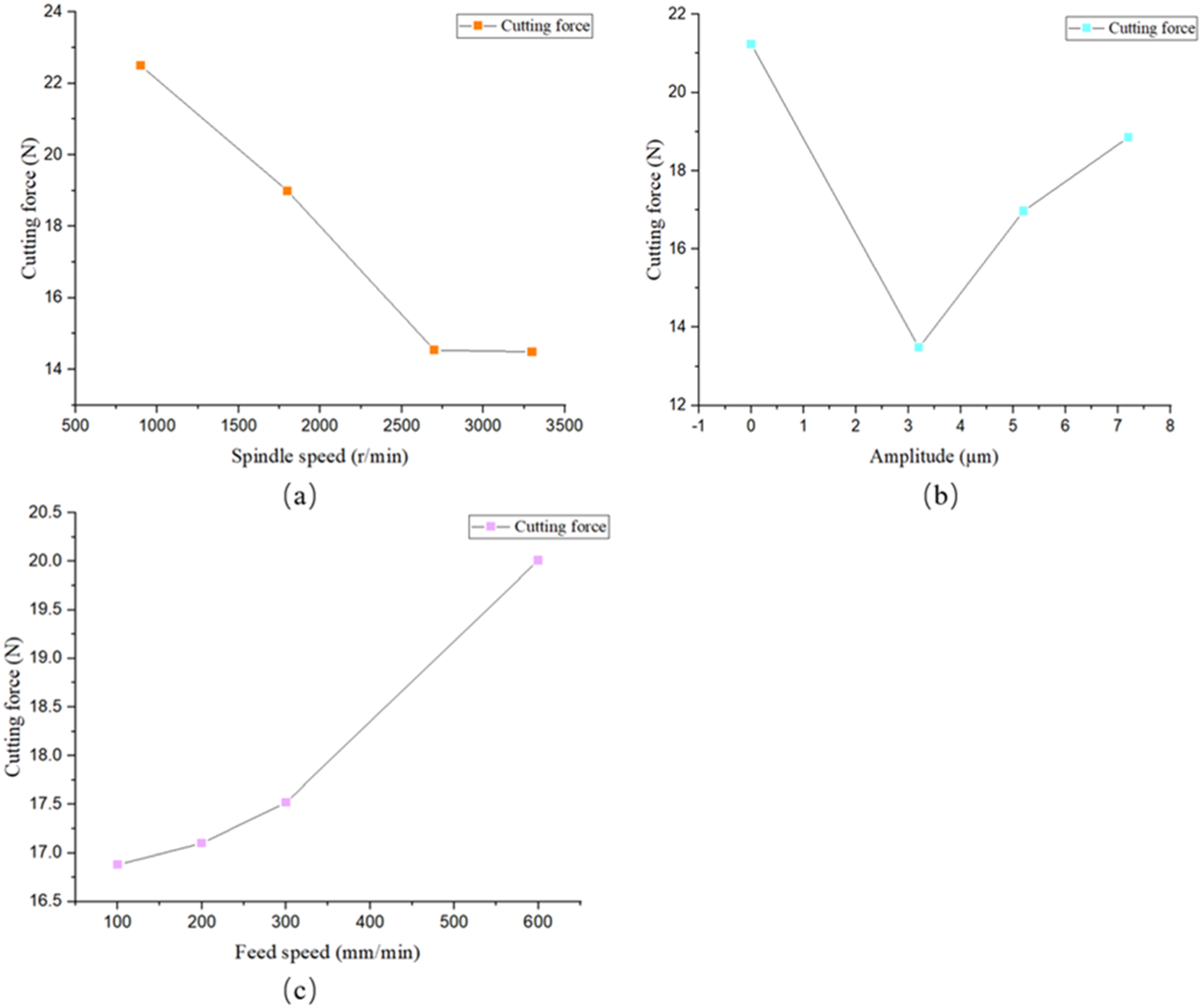
As shown in Figure 10, the interactive effect diagram of the spindle speed and amplitude reveals the collaborative influence of the two on the cutting force. When the amplitude is zero, traditional cutting, the cutting force shows a trend of first decreasing and then increasing as the spindle speed increases, indicating that there is an optimal reduction force range when only the spindle speed is increased. After introducing longitudinal torsional ultrasonic vibration, the cutting force under each amplitude level is significantly reduced. Among them, the 3.2 μm amplitude shows the best reduction effect, and its curve is overall at the lowest position. In the single-factor experiment, the phenomenon of increased cutting force when the amplitude exceeds 3.2 μm is essentially the combined result of the attenuation of the separation-reducing effect and the prominence of the impact-increasing effect: at low amplitudes, the “intermittent cutting” effect of vibration can effectively reduce the cutting load, but at high amplitudes, the additional deformation and friction loss caused by the impact counteract the separation advantage, ultimately forming a non-linear trend of “first reduction, then increase, and then saturation”. It is worth noting that at the higher amplitudes of 5.2 μm and 7.2 μm, although the cutting force is slightly lower than that of traditional cutting, its decreasing trend with the spindle speed changes becomes more gentle, and the two curves intersect in the high spindle speed area, indicating that excessive amplitude may lead to saturation of the vibration reduction effect. This interactive effect diagram directly verifies that the amplitude and spindle speed do not independently affect the cutting force, and there is a significant coupling effect between them. The optimal process matching lies in adopting an appropriate amplitude level such as 3.2 μm and combining it with a higher spindle speed to minimize the cutting force, which provides a direct basis for the collaborative optimization of process parameters for longitudinal torsional ultrasonic vibration-assisted cutting. The effect diagram of the interaction between the spindle speed and the amplitude.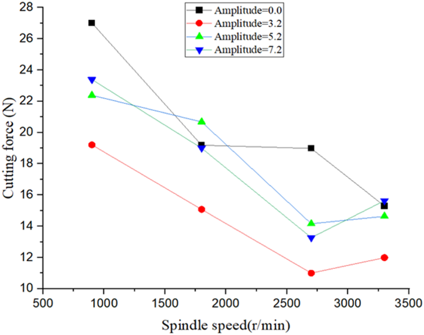
As shown in Figure 11, the interactive effect diagram of feed rate and amplitude reveals the collaborative influence mode of the two on the cutting force. Under the traditional non-vibrating cutting condition, the cutting force shows a significant upward trend that is approximately linear as the feed rate increases. After introducing longitudinal torsional ultrasonic vibration, the cutting force curves at each amplitude level all shift downward as a whole, indicating that the vibration effectively reduces the processing load. It is worth noting that under the optimal amplitude of 3.2 μm, the upward slope of the cutting force with respect to the feed rate is the flattest, demonstrating the best stability. When the amplitude increases to 5.2 μm and 7.2 μm, although the cutting force is still lower than that of traditional processing, its upward trend with respect to the feed rate becomes steeper, especially when the feed rate exceeds 300 mm/min, the increase becomes more pronounced. At a higher feed rate of 600 mm/min, the cutting force curves at 5.2 μm and 7.2 μm amplitudes approach each other or even cross, indicating that the combination of excessive amplitude and high feed rate may lead to a reduction in the damping effect. This interaction confirms the non-linear coupling relationship between amplitude and feed rate. The optimal process matching lies in using an appropriate amplitude of 3.2 μm and controlling the feed rate below 300 mm/min to achieve the best balance between cutting force and processing efficiency. The effect diagram of the interaction between feed rate and amplitude.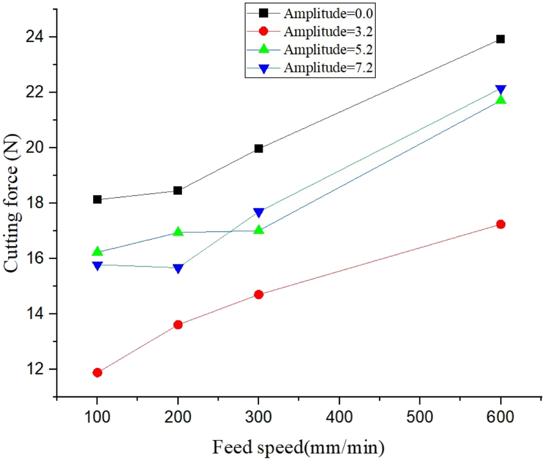
As shown in Figure 12, the interactive effect diagram of the spindle speed and feed rate reveals the collaborative influence mechanism of the two on the cutting force. At any fixed feed rate, the cutting force monotonically decreases as the spindle speed increases. This trend is particularly significant under low feed rate conditions. It is noteworthy that the curves at different feed rate levels exhibit divergent characteristics, indicating that the gain effect of the feed rate on the cutting force is partially suppressed in the high spindle speed range and amplified in the low spindle speed range. Specifically, in the low-speed zone such as 900 r/min, with the highest feed rate of 600 mm/min, the cutting force is significantly higher than other conditions. While in the high-speed zone such as above 2700 r/min, the differences between the curves at different feed rates are significantly narrowed. This interactive pattern indicates that increasing the spindle speed not only directly reduces the cutting force but also effectively alleviates the increase in load caused by the increase in feed rate. This discovery provides a key path for process optimization: when a higher material removal rate is required, it is necessary to ensure an adequate high spindle speed to counteract the negative impact of the feed rate, thereby achieving effective control of the processing load while maintaining efficiency. The effect diagram of the interaction between the spindle speed and the feed rate.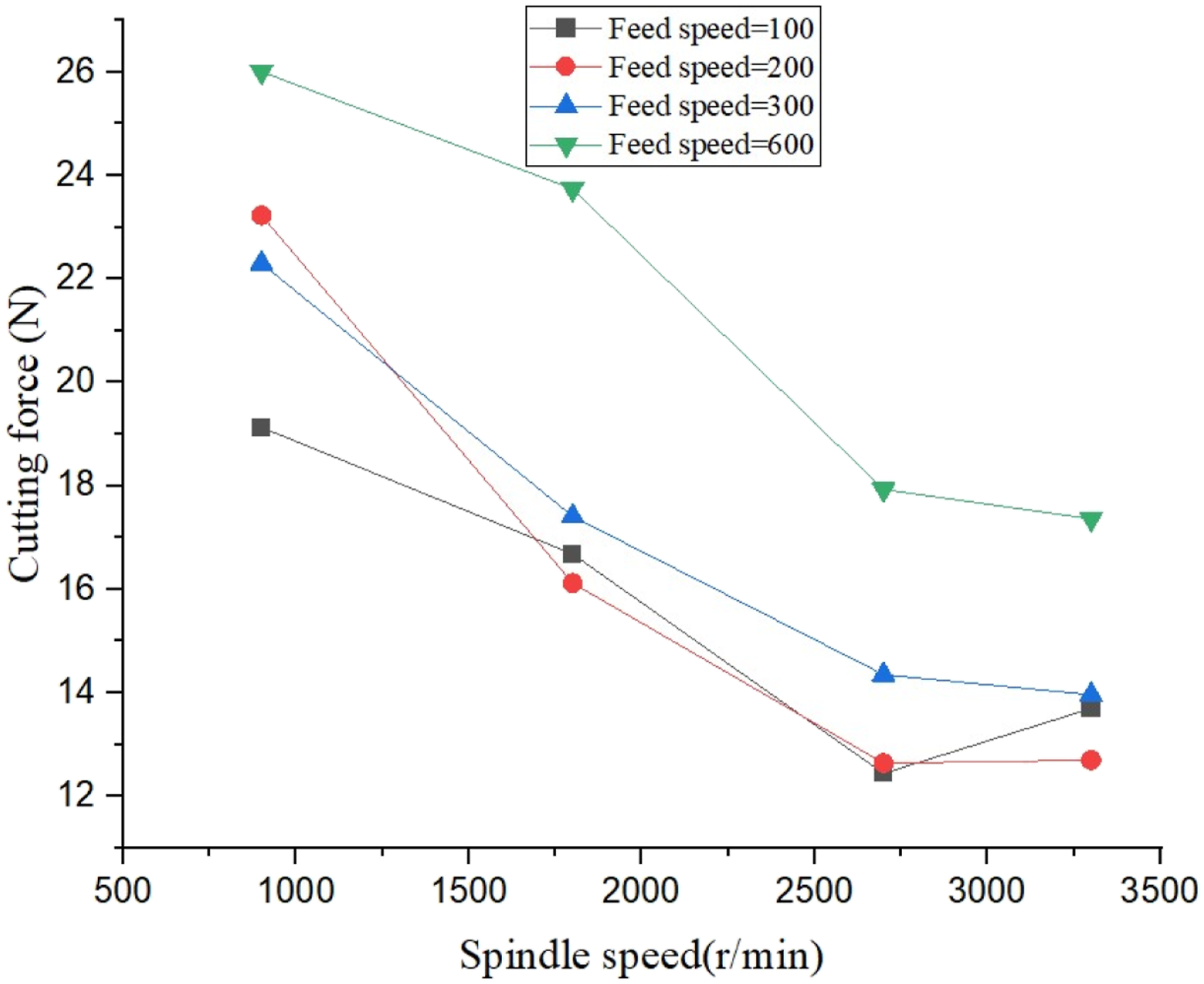
Based on the above analysis, the optimal process window recommended by this study is as follows: amplitude of 3.2 μm, feed rate of 200 mm/min, and a spindle speed of 2700 r/min or higher. Under this parameter combination, both theoretical predictions and experimental data indicate that the cutting force can be reduced to the lowest level. This optimization result stems from the synergy of multiple parameters: a 3.2 μm amplitude effectively triggers the “toolworkpiece separation” effect of longitudinal torsional ultrasonic vibration, significantly reducing the cutting force by 40%; the feed rate of 200 mm/min is optimally matched with the current amplitude, avoiding the adverse effects of the “ploughing” effect in the low-speed zone and the rapid increase in material removal rate in the high-speed zone; and a spindle speed of 2700 r/min or higher further reduces the cutting force by enhancing the strain rate and introducing the softening effect of cutting heat. The optimal process window is achieved through the synergistic effect of vibration separation, strain rate enhancement and cutting heat softening, which can effectively improve the processing quality of paper honeycomb and reduce processing defects. In LTUV processing, the tool and the paper honeycomb workpiece exhibit a high-frequency intermittent contact characteristic. Within a single vibration cycle, the tool only has an extremely short contact with the cell wall, and the rest of the time is in a separated state. The extremely short contact time and the high-frequency separation characteristic prevent the micro-heat generated by cutting from accumulating in the local cutting area in a timely manner, fundamentally suppressing the accumulation and temperature rise of cutting heat. At the same time, paper honeycomb is a porous and lightweight fiber-based structure with an extremely low thermal conductivity coefficient. The large number of internal pores further block the heat conduction path, significantly weakening the diffusion and accumulation of heat within the workpiece and further avoiding significant temperature rise in the cutting area. Therefore, in this processing, material removal mainly relies on the vibration separation effect brought by ultrasonic vibration and the brittle fracture mechanism of the paper honeycomb cell wall under dynamic load.
Morphological analysis
The influence of different amplitudes on morphology
To investigate the influence of longitudinal torsional ultrasonic vibration on the microstructure integrity of aramid paper honeycomb cores, this study conducted detailed observations on the surface morphology of the paper honeycomb cores obtained under different combinations of processing parameters. The cut paper honeycomb core samples were placed under the L100/100BD industrial inspection microscope, with the same magnification and illumination conditions, and high-resolution images were taken of representative key structural areas such as single-layer walls, doublelayer walls, and nodes. Under the fixed feed rate of 200 mm/min and spindle speed of 2700 r/min, the variation in longitudinal torsional ultrasonic vibration amplitude had a significant impact on the cutting morphology of different structural areas of the aramid paper honeycomb cores. Through a systematic analysis of the four amplitude levels, it was found that each structure responded differently to the vibration energy.
As shown in Figure 13, the nodes, as the mechanical load-bearing core of the honeycomb structure, exhibit the most significant morphological changes. During traditional cutting, the node area presents typical continuous processing damage: the fiber bundles undergo large-scale tearing under the continuous compression of the tool, forming highly irregular clusters of burrs, with a wide range of burr sizes; the surface is covered with a large amount of flocculent residues, and the fibers show obvious pulling-out rather than cutting characteristics; the geometric shape of the node undergoes significant distortion, and local crushing and collapse phenomena occur. After applying 3.2 μm ultrasonic vibration, the morphology of the nodes is fundamentally improved. The micro-impact effect generated by the highfrequency vibration promotes brittle fracture of the fibers, and the burrs transform into uniformly sized fine fracture points, with a significantly reduced distribution density; the coverage of flocculent substances is greatly reduced, and the surface cleanliness is significantly improved; the node contour remains intact, and the crushing phenomenon basically disappears. When the amplitude increases to 5.2 μm, local quality regression begins to occur in the node area, and the burr size in some areas increases, and intermittent burr bands are distributed. Under the 7.2 μm amplitude condition, excessive cutting marks appear at the node area, and local areas show crushing and fracture phenomena, indicating that the vibration energy has exceeded the material’s tolerance threshold. Microscopic morphology of the cut surfaces under different amplitudes.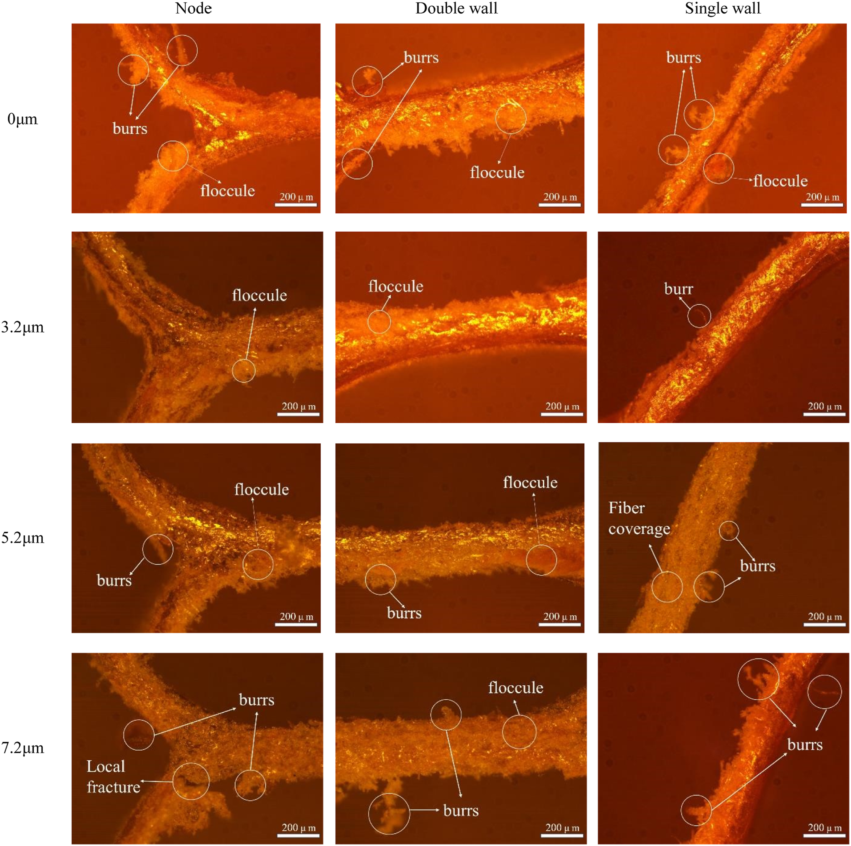
The morphological changes in the double-layer wall junction area mainly manifest in the distribution of burrs and surface quality. During traditional processing, a continuous burr band forms at the double-layer wall junction, with the burrs densely distributed along the wall edge and uneven height; the surface is covered with a large amount of flocculent substances, and the fibers show obvious stretching and fracture characteristics. Although the degree of crushing deformation in the wall area is relatively milder than that in the node area, local depressions can still be seen. Under the 3.2 μm amplitude condition, the morphology of the double-layer wall is significantly improved. The burr distribution becomes sparse and uniform, and the height consistency improves; the coverage of flocculent substances is significantly reduced, and the wall junction area presents clear edges. When the amplitude increases to 5.2 μm, the burr size shows a slight increase trend, and the distribution uniformity decreases. Under the 7.2 μm condition, the burr size at the double-layer wall area becomes significantly larger, and the number of flocculent substances also increases, but the overall structural integrity remains in a relatively good state. The single-layer wall area shows comprehensive changes in crushing deformation, burr generation, and flocculent substance distribution. During traditional cutting, the single-layer wall shows local indentations, the burrs are unevenly distributed, and the surface is covered with a large amount of flocculent fiber residues. These flocculent substances mainly originate from the “connection of broken fibers” structure that is not completely cut off, seriously affecting the surface smoothness. Under the 3.2 μm amplitude condition, high-frequency vibration through effective material shearing is achieved, the crushing phenomenon at the single-layer wall basically disappears, and the burr size becomes uniform. At the same time, the high-frequency acceleration generated by the vibration significantly reduces the coverage of flocculent substances and presents clearer cutting lines on the surface. As the amplitude increases to 5.2 μm, a few small-sized burrs appear at the single-layer wall area, and the coverage of flocculent substances is slightly increased compared to the 3.2 μm condition. When the amplitude increases to 7.2 μm, the flocculent substances are relatively dense in the single-layer wall area, and a large number of larger burrs also appear.
To further quantitatively evaluate the influence pattern of longitudinal-torsional composite ultrasonic vibration processing on the surface quality of honeycomb cores under different amplitudes, and to overcome the limitations of the original qualitative visual observation, the ImageJ image processing software was used to conduct quantitative analysis of the microscopic morphology images of honeycomb cores under different processing conditions. The core evaluation indicators of average burr height and effective node area were statistically analyzed respectively. The corresponding bar charts of the quantitative results under different amplitudes are shown in Figure 14 (a) and Figure 14 (b). From the results, it can be seen that compared with traditional cutting, ultrasonic vibration processing can significantly reduce the edge burr height of honeycomb cores and effectively improve the integrity of honeycomb nodes. This verifies the process advantages of LTUV processing at the quantitative level. Specifically, as the amplitude increases, the average burr height shows a trend of first decreasing and then increasing, while the proportion of effective node area shows a trend of first increasing and then decreasing. Both reach the optimal state at an amplitude of 3.2 μm: at this time, the average burr height drops to 4.1 ± 0.4 μm, which is 67.7% lower than that of traditional cutting; the proportion of effective node area increases to 93.2 ± 2.7%, which is 52.0% higher than that of traditional cutting. This indicates that the burr control effect and node integrity of the honeycomb core are the best under this parameter, and the processing quality of the honeycomb core reaches the optimal state. When the amplitude exceeds 3.2 μm, excessive vibration impact will lead to a decrease in processing stability, and the burr height gradually recovers, and the node integrity gradually deteriorates. The influence of amplitude on the height of the honeycomb core burr and the effective node area: (a) The average height variation pattern of the honeycomb core burrs under different amplitudes, (b) The variation law of the proportion of the effective node area of the honeycomb core under different amplitudes.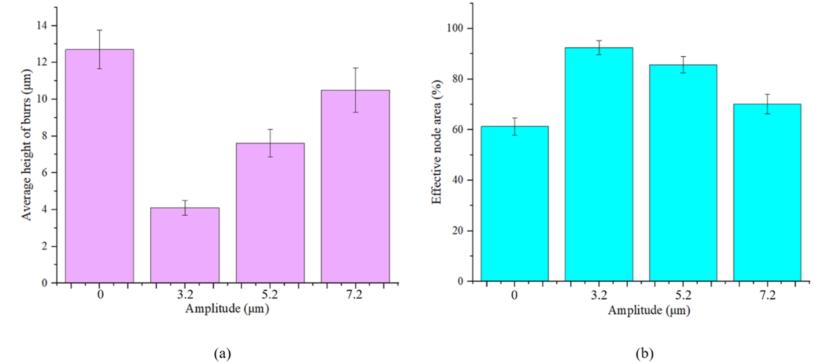
Defect analysis
To evaluate the improvement effect of longitudinal torsional ultrasonic vibration on the processing quality of aramid paper honeycomb core, this study compared and analyzed the surface defect characteristics under the traditional cutting condition of 0 μm and the optimal ultrasonic vibration condition of 3.2 μm. Under the fixed process parameters of feed rate of 200 mm/min and spindle speed of 2700r/min, through the observation with XDS/10A high-definition video microscope, the essential differences in the forms of burrs, crushing deformation and flocculent residue between the two processing methods were revealed.
Based on the microscopic morphology comparison results shown in Figure 15, the honeycomb wall edges of the traditional cutting method were distributed with a large number of irregular burrs, which presented a fibrous bundlelike tearing morphology with varying heights, indicating that the material underwent significant plastic deformation and fiber drawing during continuous shearing. In contrast, the cutting edge of the ultrasonic vibration-assisted cutting was more smooth, with significantly reduced burr size and uniform distribution, presenting fine fracture point-like features. This improvement is attributed to the periodic separation effect of the ultrasonic vibration between the tool and the workpiece, which reduces the average cutting force and causes the material to tend to undergo brittle fracture rather than plastic tearing. In terms of crushing deformation, the honeycomb structure of the traditional cutting showed obvious local collapse, the wall surface experienced internal indentation deformation, and the geometric shape of some honeycomb units was distorted, indicating that the static cutting pressure exceeded the buckling critical load of the thin-walled structure. The ultrasonic vibration processing samples showed good structural integrity, clear node contours, and significantly improved wall surface flatness. Node crushing significantly reduces the effective compressive stiffness of the core. In a sandwich panel, this localized collapse can act as an initiation point for face-core debonding under impact loads. The mechanism lies in that the high-frequency micro-impact load replaced the continuous static pressure, effectively dispersed the cutting force, and avoided stress concentration leading to structural instability. In terms of flocculent residue, the surface of the traditional cutting was covered with loose fibers and resin debris, forming a distinct flocculent or fluffy surface layer, which was a “connection remaining after separation” structure.
38
The fibrous residue observed in traditional machining tends to absorb excessive resin during the bonding process, potentially leading to resin starvation at the bond line.
39
The surface of the ultrasonic vibration processing was cleaner, with a significant reduction in flocculent residue, revealing a clearer base material and cutting texture. This is because the ultrasonic vibration provided high-frequency acceleration, enhancing the instantaneous shearing ability of the tool on the fibers, and helping to promptly discharge the debris from the processing area. Comparison chart of ultrasonic and traditional cutting processing defects.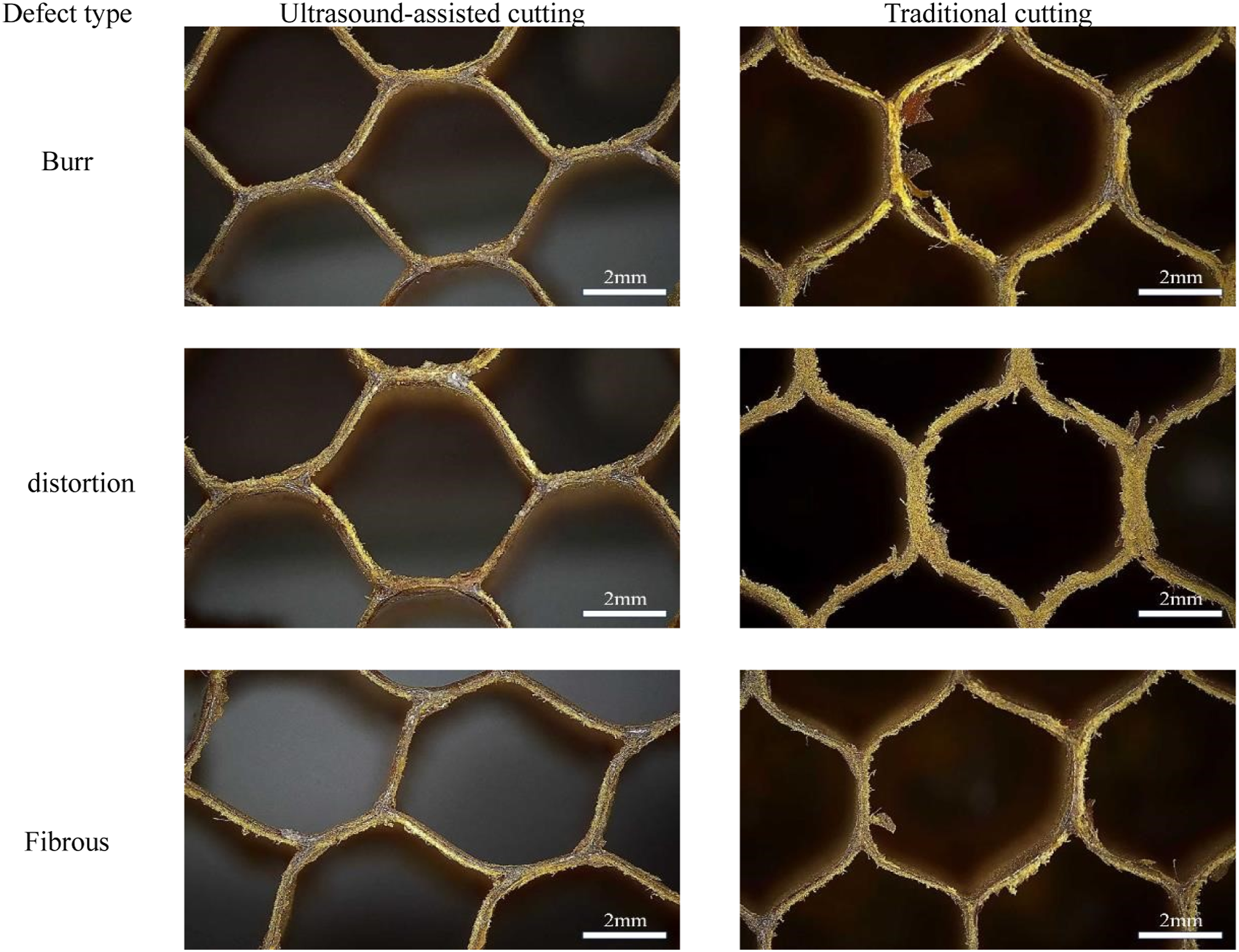
In conclusion, longitudinal torsional ultrasonic vibration changes the microscopic mechanism of material removal from continuous plastic shearing to intermittent brittle fracture, systematically improving the cutting surface quality of the paper honeycomb core. Its core advantage lies in significantly suppressing burr generation, reducing structural crushing, and obtaining a cleaner processing surface, providing a reliable processing scheme for the precise processing of high-quality honeycomb cores.
The influence of these microscopic defects extends beyond surface morphology to the structural integrity of the final sandwich panel. As illustrated in Figure 16 (a), the irregular burrs and fluff residues generated during traditional machining can hinder the flow of adhesive, leading to air entrapment and discontinuous fillet formation. Furthermore, the node crushing defects act as geometric imperfections that cause stress concentration under compressive loads, potentially initiating premature core-face debonding. In contrast, as illustrated in Figure 16 (b), the defect-free and straight cell walls achieved by LTUV facilitate the formation of optimal adhesive fillets, thereby ensuring uniform load transfer and maximizing the interfacial bonding strength of the sandwich structure.
40
Schematic diagram of machining quality - structural performance correlation: (a) Traditional machining, (b) LTUV machining.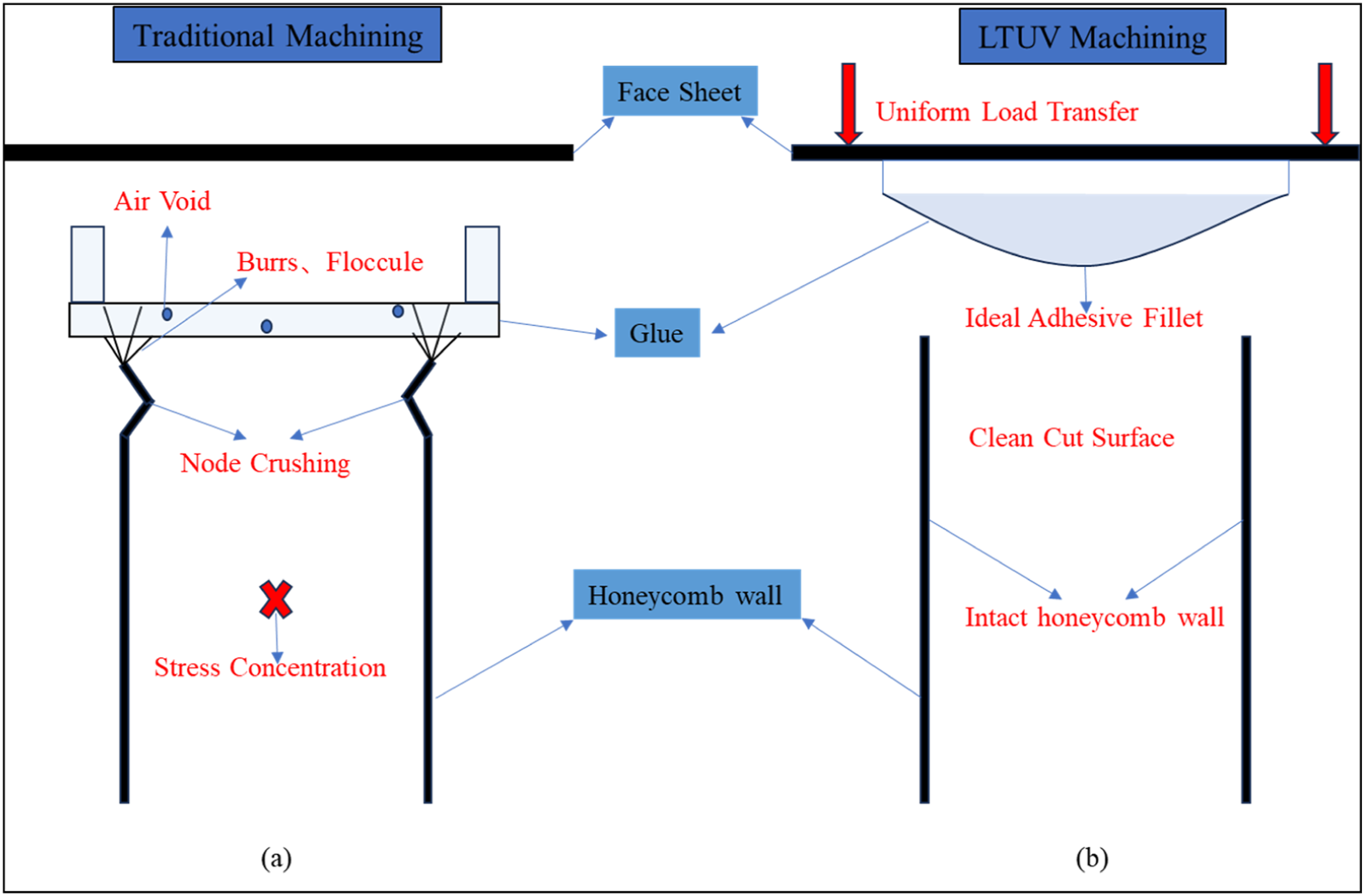
Conclusions
This paper systematically investigated the influence of process parameters of longitudinal torsional ultrasonic vibration-assisted cutting on the cutting force and surface integrity of aramid paper honeycomb cores through full-factor experimental design and variance analysis. It also compared and analyzed the differences in surface morphology between traditional cutting and ultrasonic vibration processing conditions. Based on the experimental data and morphology observation results, the main conclusions are as follows: (1) The torsional-combined ultrasonic vibration reduces the cutting force by approximately 40% compared to traditional cutting by introducing a high-frequency periodic separation effect between the tool and the cutter. The spindle speed and vibration amplitude are the most significant factors affecting the cutting force. The optimal parameter combination is an amplitude of 3.2 μm, a feed rate of 200 mm/min, and a spindle speed of 2700 r/min. At this point, the axial cutting force Fz is at its lowest. (2) The amplitude exerts a non-linear regulatory effect on cutting force and surface morphology: when the amplitude increases from 0 μm to 3.2 μm, the cutting force significantly decreases and the surface quality is optimal; when the amplitude further increases to 7.2 μm, the cutting force rebounds and tends to saturate, with increased burrs in local areas and degradation of surface quality. (3) There is a significant interaction effect among the process parameters: the coupling effect between the spindle speed and the amplitude determines the control effect of cutting force. A high spindle speed can alleviate the increase in cutting force caused by a high feed rate; 2700 r/min is the critical value for spindle speed control, and beyond this value, the reduction effect of cutting force gradually diminishes. (4) The torsional ultrasonic treatment changes the material removal method from continuous plastic shear to intermittent brittle fracture. Under the optimal parameters, the average burr height of the honeycomb core is reduced by 67.7% compared to traditional cutting, and the effective node area ratio is increased by 52.0%. (5) Determine the optimal process window for longitudinal torsional ultrasonic cutting of aramid paper honeycomb core: an amplitude of 3.2 μm, a feed rate of 200 mm/min, and a spindle speed of ≥2700 r/min can achieve the minimum cutting force and the best surface quality.
This study still has certain limitations. It only conducted experiments on a single type of aramid paper honeycomb material, and the range of research parameters was relatively limited due to the constraints of hardware conditions. The surface integrity characterization methods can still be further enriched. The theoretical model established is based on certain ideal assumptions and does not fully consider the multi-physics field coupling effect. In the future, the types of materials and process parameters will be expanded, more precise characterization methods will be introduced, the multi-physics field coupling theory model will be improved, the microscopic processing mechanism will be further revealed, and the longitudinal-twisting composite ultrasonic vibration processing technology will be further optimized.
Footnotes

Funding
The authors disclosed receipt of the following financial support for the research, authorship, and/or publication of this article: This study was supported by National Natural Science Foundation of China (No. 52465050), China Scholarship Council (No. 202408360181), Special Program of “Chief Technology Officer for Jiangxi Jiande Industrial Co., Ltd.” under Jiangxi Provincial Base and Talent Plan, China (No. S202520068), Jiangxi Provincial Natural Science Foundation, China (No. 20212BAB204001).
Declaration of conflicting interests
The authors declared no potential conflicts of interest with respect to the research, authorship, and/or publication of this article.