
Abstract
Sandwich panels in engineering applications are typically subjected to varied support and loading scenarios. However, traditional core designs based on predefined geometries often exhibit significant performance deterioration when service conditions shift. This study employs a parametric level set–based topology optimization method to maximize core stiffness under multiple representative conditions. Numerical results demonstrate that both support conditions and loading patterns have a decisive influence on global stiffness; the four-edge fixed configuration with concentrated loading achieves the highest stiffness, while the four-corner supported configuration with uniformly distributed loading exhibits the lowest stiffness due to restricted load-transfer efficiency. Unlike studies limited to comparing fixed topological families, the proposed framework automatically generates a synthesized honeycomb-like structure (SHLS) with adaptive load-transmission paths under multi-condition. Three-point bending simulations and experiments on selective laser melting (SLM)-fabricated AlSi10 Mg specimens reveal that, at identical core thickness, the proposed core achieves the highest specific stiffness and the highest specific energy absorption (SEA). Compared with traditional honeycomb-like structure (THLS) and honeycomb structure (HS), the specific stiffness of the SHLS is enhanced by up to 27% and 5%, respectively. Numerical simulations and experimental results exhibit high consistency throughout the loading process, confirming the reliability of the modeling framework.
Introduction
Sandwich structures are foundational in lightweight engineering due to their high specific stiffness and multifunctional potential.1–4 Compared to stochastic foams, periodic lattice cores (such as honeycombs and trusses) offer superior tunability of mechanical properties, allowing for precise control over stiffness, strength, and energy absorption.5–8 However, the mechanical performance of these systems is often limited by localized failure modes, such as face-core debonding and core collapse, which necessitate the development of more refined topological configurations to ensure structural integrity. Achieving an optimal balance between structural complexity and manufacturability remains a critical challenge. 9
The optimization of periodic porous cores has evolved from traditional size and shape optimization of predefined geometries to direct optimization of material distribution. Rathbun et al. 10 and Liu et al. 11 explored the weight minimization of sandwich panels with predefined core topologies using analytical and homogenization-based approaches, respectively. Recent studies have evaluated how core geometry influences impact resistance and acoustic performance.12–14 Patel and Patel 15 systematically compared predefined topologies (e.g., square, circular, and octagonal cores) under extreme air-blast loading, identifying circular configurations as optimal for minimizing dynamic deflections. While these studies provide valuable benchmarks, they are primarily limited to selecting parameters within fixed topological families. Topology optimization (TO) represents a distinct paradigm by allowing free-form material evolution within a design domain, offering expanded freedom to synthesize architectures that transcend standard geometric shapes. Various TO techniques, including SIMP-based and multiscale frameworks, have been developed to enhance the stiffness and multifunctionality of lattice cores.16–20 Hu et al. 21 also emphasized that macroscopic TO without periodicity constraints often leads to non-uniform material concentrations that significantly decrease load-carrying capacity in certain engineering scenarios, underscoring the practical necessity of periodic architectures for resisting uncertain external loads.
A critical but often overlooked aspect in sandwich panel design is the sensitivity of the optimized topology to varying boundary and loading conditions. Structures optimized for a single load case frequently exhibit rapid performance deterioration in complex service environments where support configurations or force distributions may shift. Gao et al. 22 demonstrated that neglecting load and geometric uncertainties in single-condition designs leads to substantial performance deterioration in practical service. While multi-condition optimization has been explored in compliant mechanisms and general frames to improve robustness under loading uncertainties,23,24 its systematic application to 3D sandwich core design remains relatively limited. Current literature highlights that while high-performance materials improve face-sheet properties, the global structural reliability is decisively governed by the synergy between face-sheet flexural stiffness and core shear stiffness, where the core’s adaptive load-transmission path plays a central role.25–27
To address this gap, the present study employs a parametric level-set method (LSM) to optimize 3D sandwich core architectures under multiple representative
Method
Parameterization of the LSF
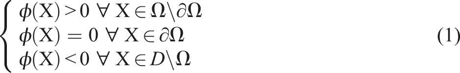
For the closed material domain
Geometry mapping
To perform finite element analysis (FEA), the LSF needs to be shifted to a physical model. For the proposed method, an exact Heaviside function
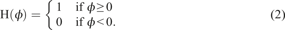
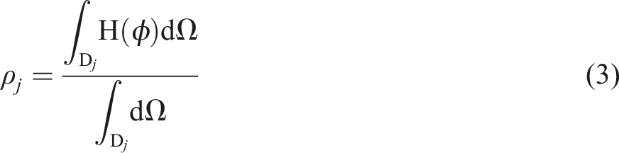
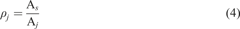
The ersatz material model is adopted here for FEA for convenience, as the design domain can be meshed once and for all while excluding mesh regeneration or modification. The transformation of the ersatz material model from the LSF is equivalent to the transformation of the density distribution

Nodal sensitivity
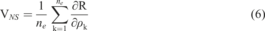
During the optimization process, update information is iteratively renewed to update the candidate design. LSF evolution is driven based on nodal sensitivity. Here, the nodal sensitivity VNS is defined as the average sum of the sensitivities of the elements that contain the node, which reads as follows:
Subdomain partitioning and constraint imposition for fully periodic structures
The fully periodic structure shown in Figure 1 consists of multiple identical sub-structures. By discretizing the design domain with an element mesh, the total number of subdomains and the number of element densities per subdomain are given as: Schematic diagram of fully periodic structure.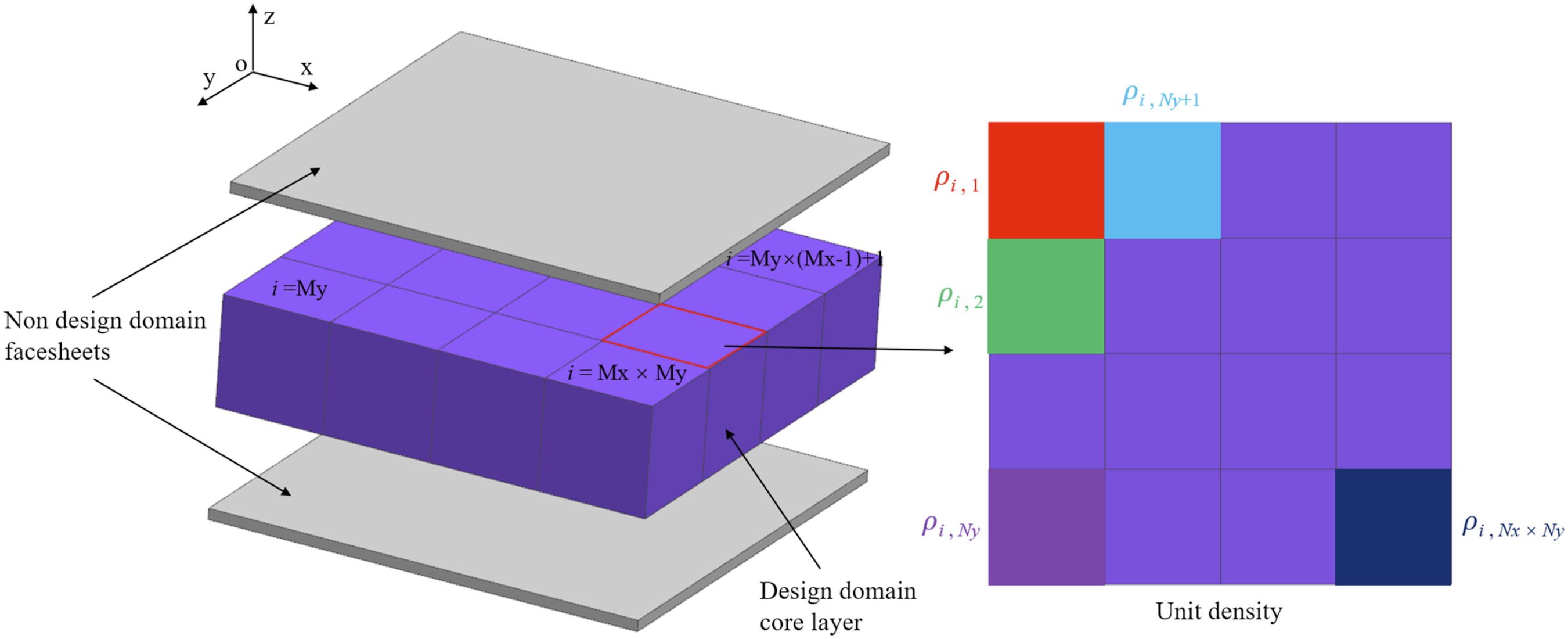


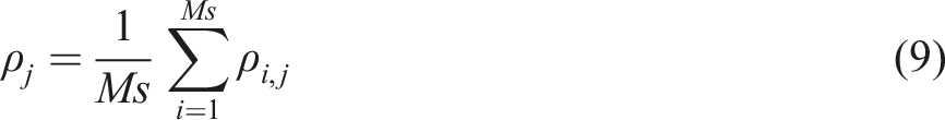
To implement periodic constraints within the framework of fully periodic topology optimization, it is required that the relative density and sensitivity for elements sharing the same index in each subdomain be uniform. Consequently, these values are averaged and redistributed across all corresponding elements throughout the optimization iterations, which is expressed as:
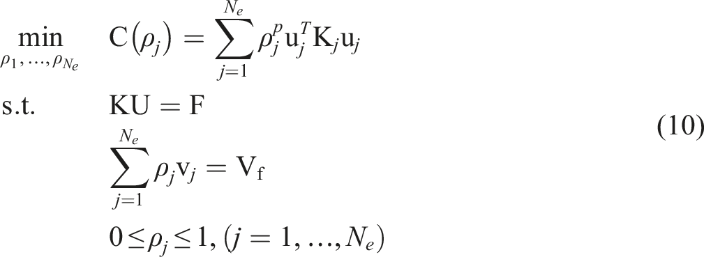
Compliance minimization problem
In this subsection, a standard compliance minimization problem for the statically loaded linear elastic structure subject to a constraint on the material volume is defined. The mathematical optimization model takes the following form:
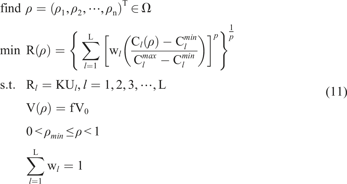
Formulation of multi-condition topology optimization
Since the differences between the sub-objective functions and their ideal points under different conditions often vary by several orders of magnitude, normalization is utilized to eliminate the impact of units and magnitudes. The mathematical formulation is given by:
Sensitivity analysis
The sensitivity of the multi-load case objective function
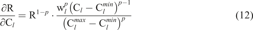
For the case of compliance minimization, the derivative of objective function with respect to the design variable
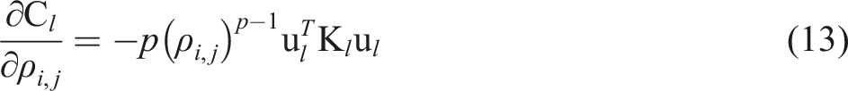
In conjunction with the periodic density mapping scheme and the chain rule, the final sensitivity expression for the multi-load case objective function relative to the subdomain control point density

Numerical stability and parameter sensitivity study
To assess the numerical stability and robustness of the proposed framework, a parametric sensitivity study was conducted on a 3D benchmark model, as shown in Figure 2, revealing that the optimized topologies remain highly consistent across varying mesh densities and filter radii, which confirms the mesh-independency and algorithmic stability of the solver, while increments in volume fraction result in a logically consistent thickening of structural members without altering the fundamental topological layout. Parametric sensitivity study of the optimized topology under varying mesh densities, filter radii, and volume fractions.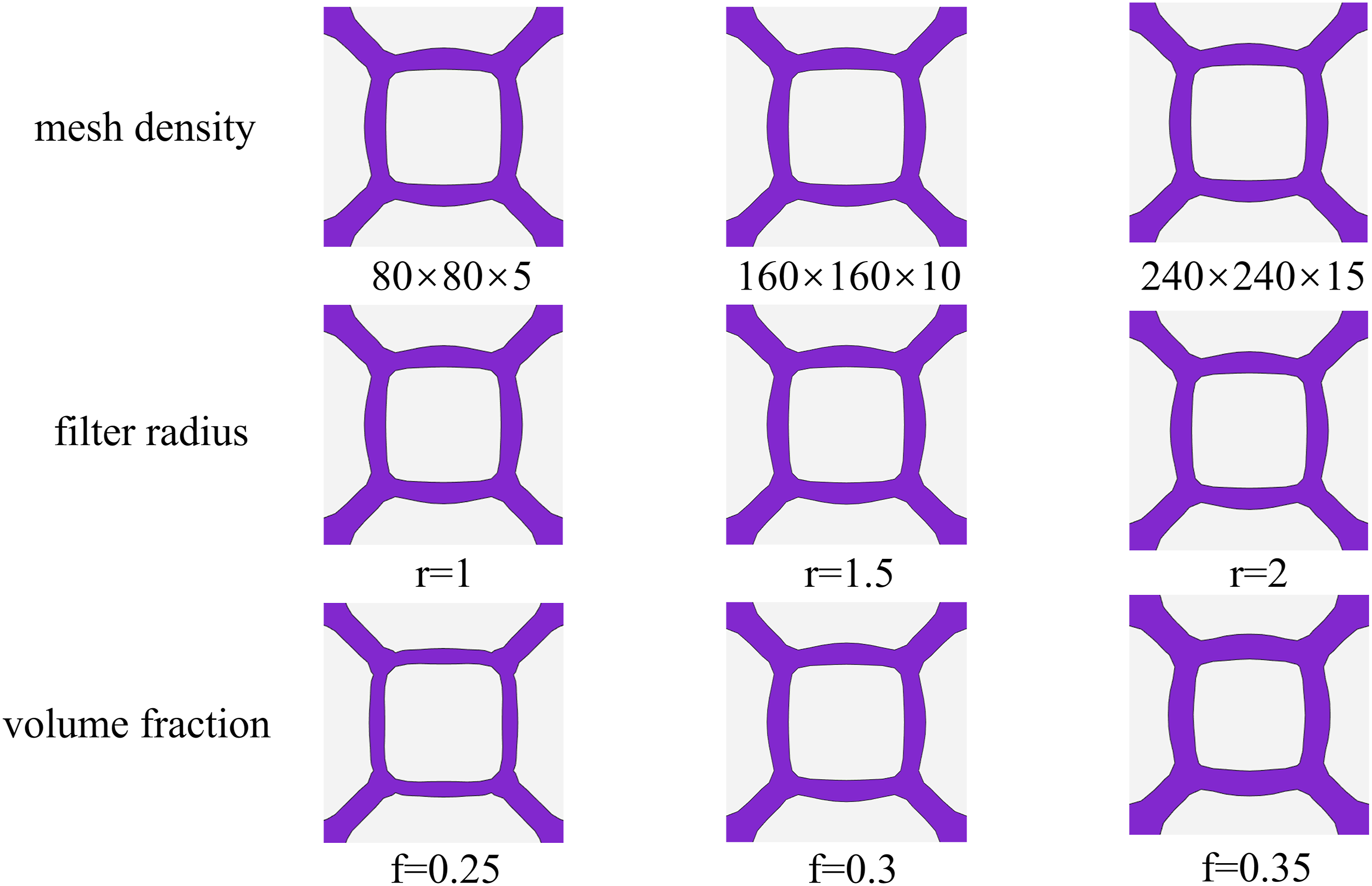
Numerical examples
This section presents a topology optimization framework for sandwich panel core layers based on the LSM. Several numerical examples are provided, targeting the minimization of structural compliance to maximize stiffness. The material properties and optimization parameters are defined as follows: the elastic modulus of the solid phase is
Design domain and boundary conditions
To evaluate and optimize the stiffness performance of sandwich panel cores, four combinations were established: two boundary types (four-edge clamped and four-corner supported) and two load types (concentrated and uniformly distributed). The design domain for the core layer is defined as a 3D rectangular prism with dimensions of 160 mm × 160 mm × 10 mm, as shown in Figure 3. The optimization domain comprises the entire sandwich assembly, where the upper and lower face sheets are defined as non-designable regions with a constant thickness of 1 mm to ensure the focus remains on the topological evolution of the core layer. For better visualization of the complex internal core architectures, the non-designable face sheets are intentionally hidden in the following topology result figures. Schematic diagram of four single operating conditions.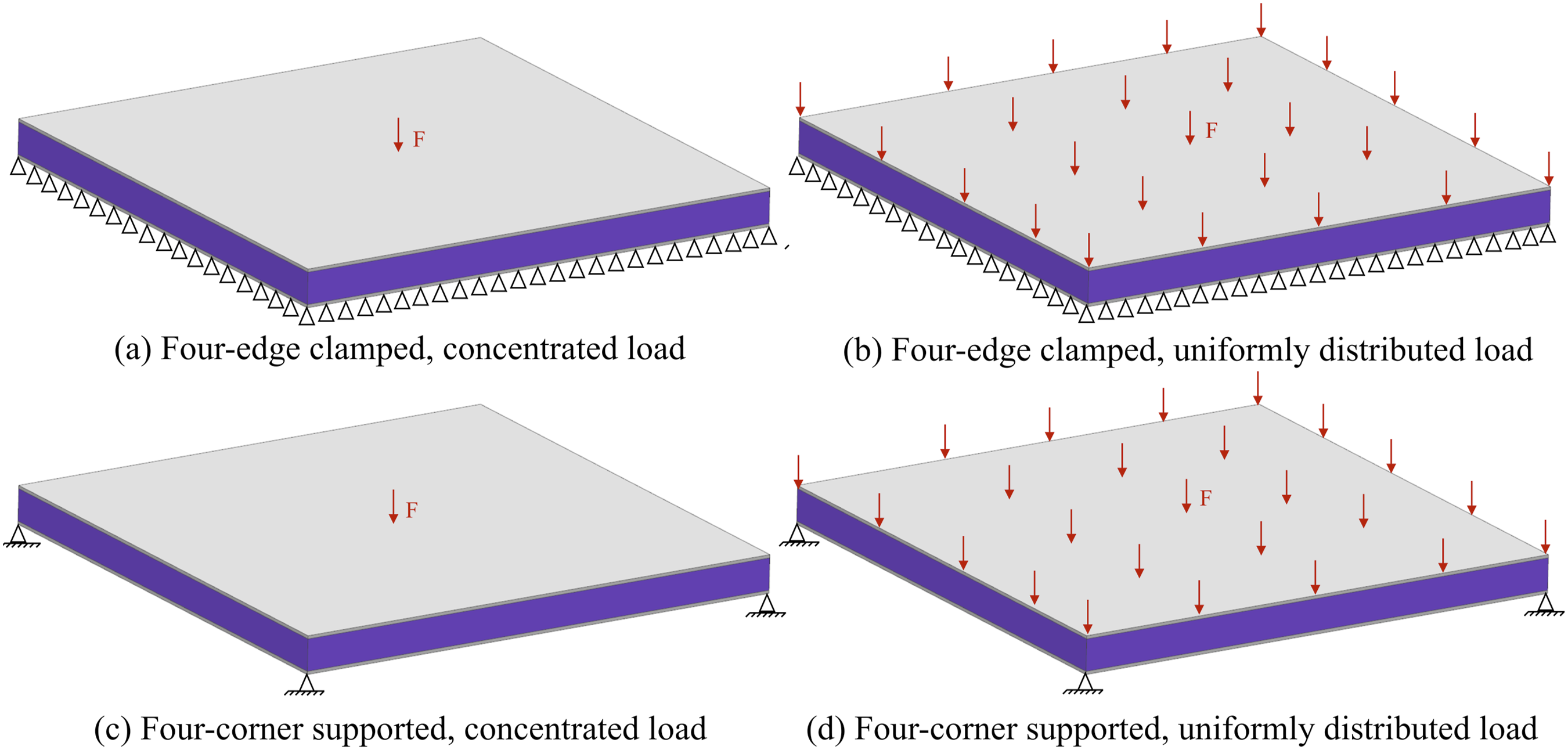
Single-condition optimization results
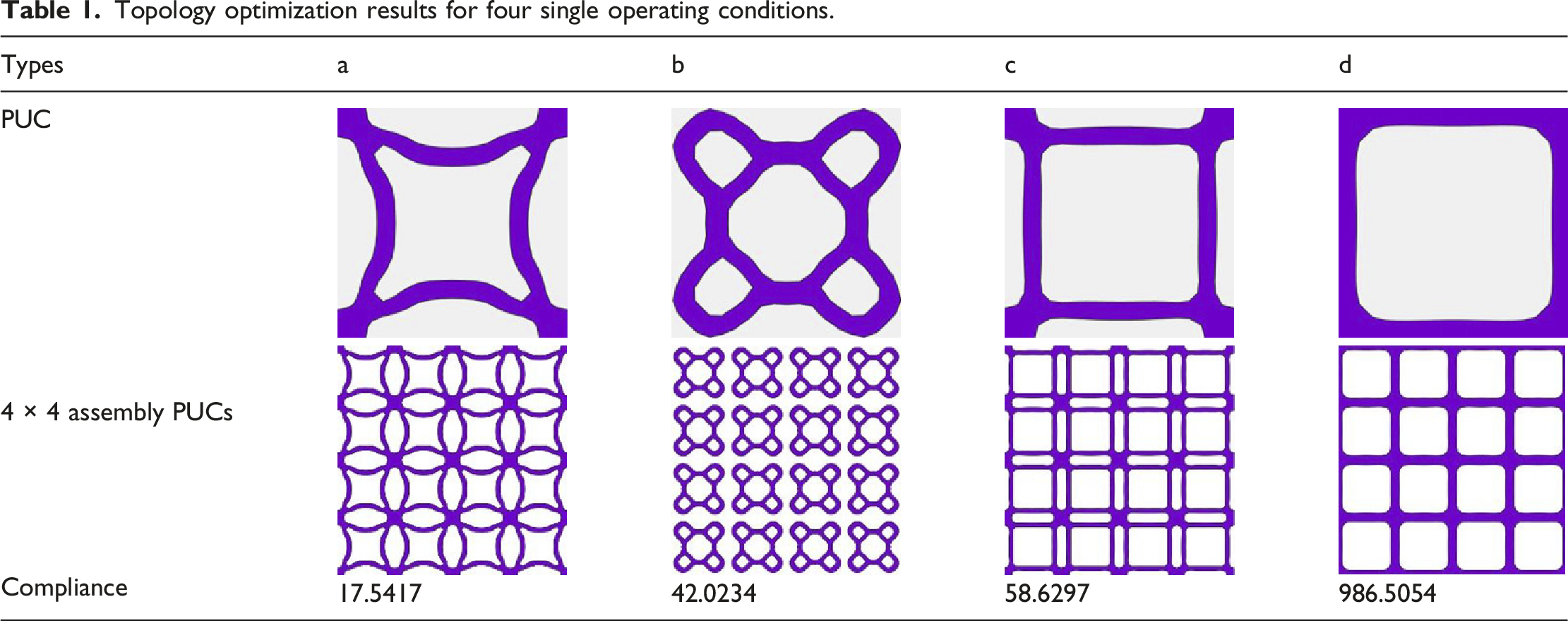
Independent optimization was conducted for four representative load cases. As shown in Figure 4, the optimal topology exhibits strong dependence on boundary conditions. The four-edge clamped configurations (Cases a, b) promote distributed load paths, leading to the formation of orthogonal or radial rib patterns. Conversely, the four-corner supported configurations (Cases c, d) concentrate material into localized diagonal struts to bridge the unsupported spans. Topology optimization results for four single operating conditions.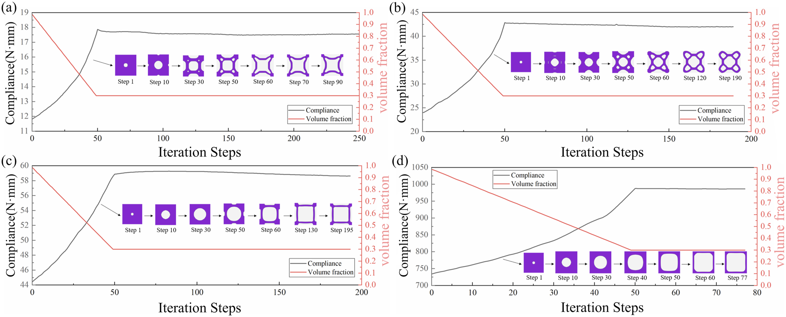
Topology optimization results for four single operating conditions.
Multi-condition optimization results
Comprehensive performance results and comparisons.
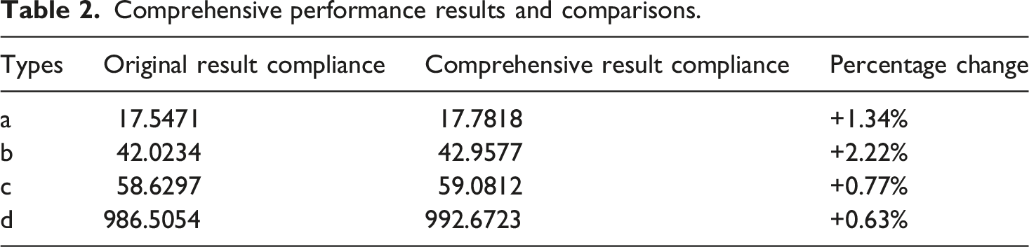
Figure 5 illustrates the iterative evolution of the periodic microstructure and its corresponding 4 × 4 periodic structure during the multi-condition optimization process. The optimization converged in 98 iterations, with load-transmission channels progressively developing from the central region. By iteration 40, a preliminary cross-shaped topology emerged. Redundant structural members were subsequently eliminated, resulting in a symmetric and continuous topology with clearly defined load-transfer paths. The 4 × 4 periodic assembly ensures high geometric consistency, facilitating a balanced mechanical response across diverse loading orientations while enhancing manufacturing robustness through standardized unit cell replication. Iterative results of topology optimization under Multi-condition.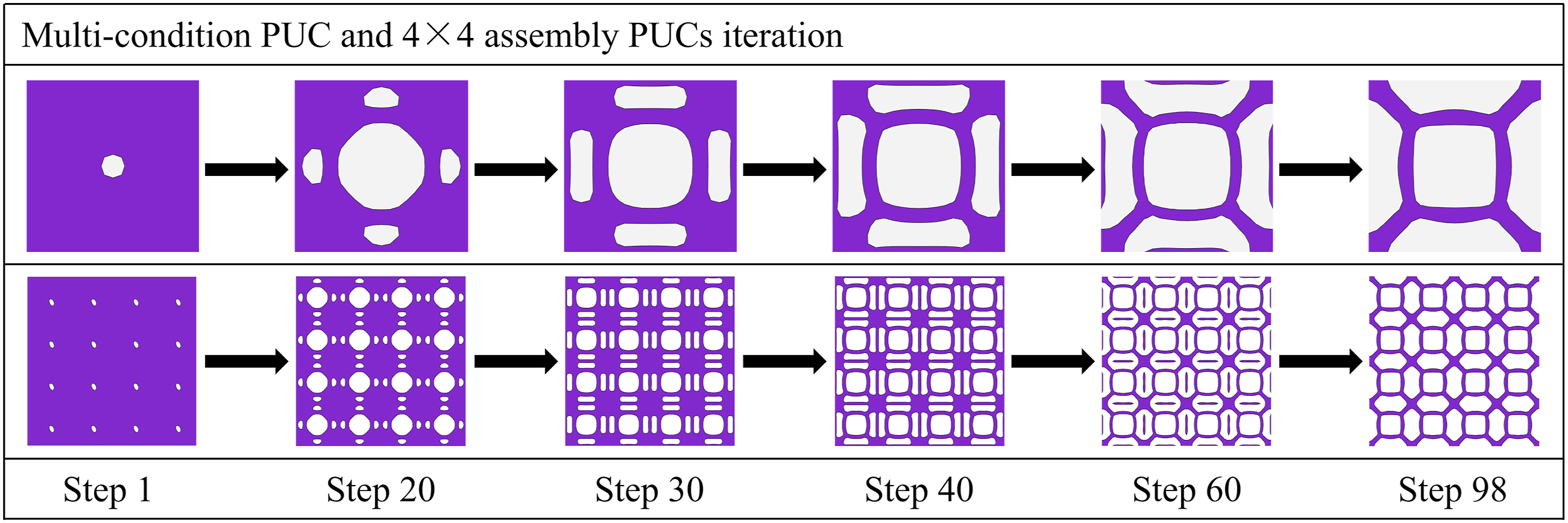
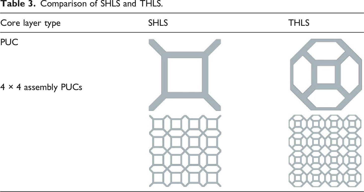
Comparison of SHLS and THLS.
Three-point bending of sandwich panels
FE model
Three-point bending simulations of the sandwich panels were conducted using ANSYS finite element software following the principles of ASTM C393/C393 M. The loading indenter and support rollers both have a diameter of 20 mm. A constant support span of 160 mm was maintained in the numerical model. The specimen dimensions are 200 mm × 50 mm × 12 mm, incorporating 1 mm thick face-sheets. The bending simulations were conducted at a constant crosshead displacement rate of 1.5 mm/min.
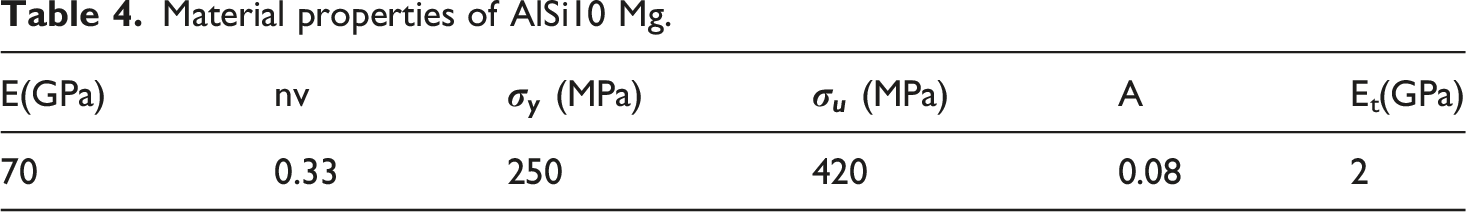
Material properties of AlSi10 Mg.
Three-point bending of single-condition and SHLS
To facilitate a rigorous performance comparison, the core wall thickness was standardized at 1 mm across all sandwich panel configurations. Figure 6 illustrates the von Mises equivalent stress distributions and deformation contours for the four single-condition benchmarks (a–d) and the SHLS (e). Comparison of single-condition and SHLS three-point bending simulation results.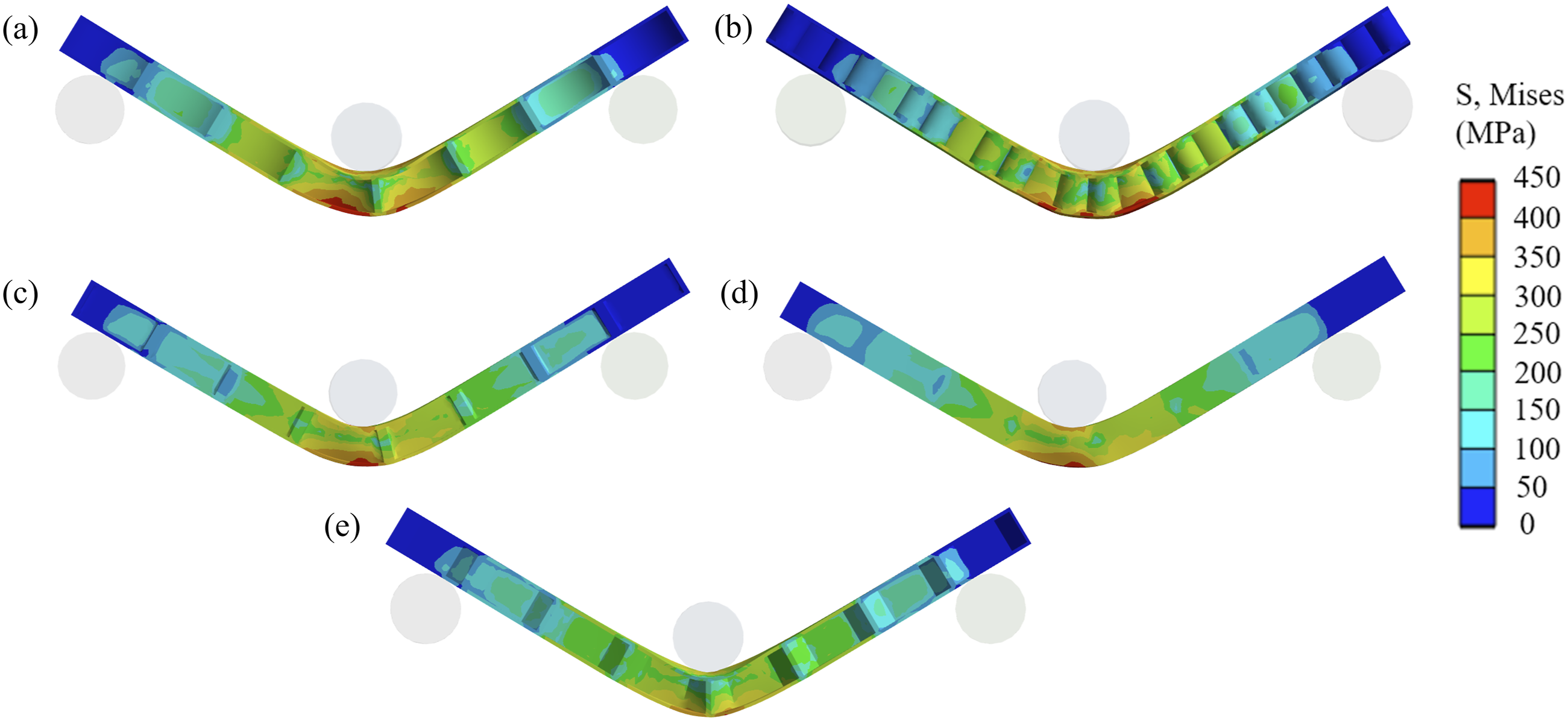
The stress contours for the three-point bending simulation of the sandwich panel exhibit a progressive stress attenuation radiating from the loading center toward the longitudinal supports. For the single-condition designs (Figure 6(a)–(d)), the stress distributions exhibit a pronounced dependency on the specific loading environment. In contrast, the SHLS (e) demonstrates superior comprehensive performance. The stress field of the SHLS is more homogeneous, characterized by high-stress regions manifested as continuous, short-range bands. Furthermore, the SHLS (e) achieved the lowest mass of 91.1 g across all scenarios.
A comparative analysis was conducted to evaluate the mechanical properties of the single-condition designs versus the SHLS. Figure 7(a) and (c) illustrate the load-displacement curves and peak load for the five core configurations. Structure (b) exhibits the highest peak load and superior load-bearing capacity during the post-elastic phase, primarily attributed to its higher mass density. Structures (c) and (d) follow comparable trajectories but exhibit lower load responses. The SHLS (e) displayed a marginal reduction in load compared to structure (a), though both exhibited nearly identical trends. Bending performance characterization of single-condition cores and SHLS (a) Load-displacement curve; (b) SEA curve; (c) Peak load; (d) Specific stiffness.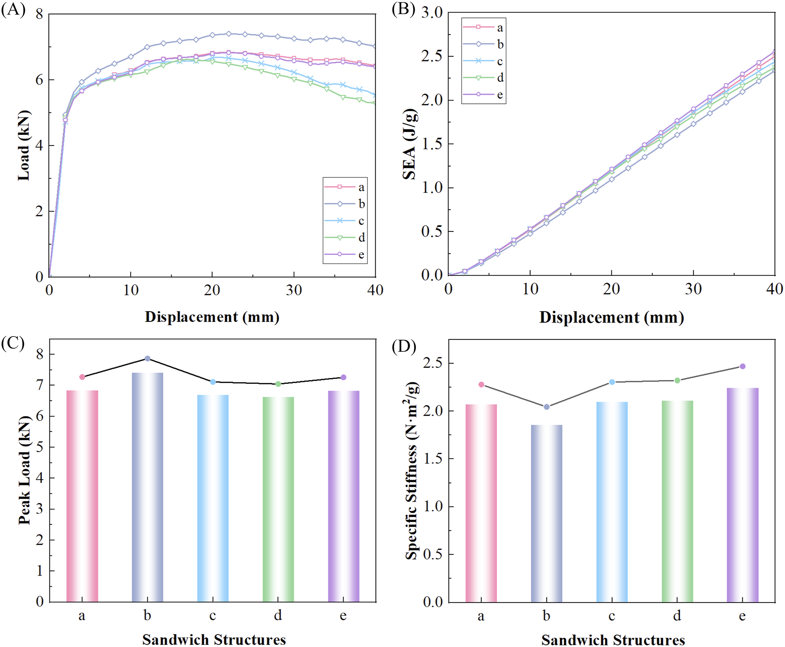
Figure 7(b) displays the SEA curves for five different core layers, with the SHLS (e) exhibiting the best performance. Its SEA value exhibits a monotonic increase with displacement, reaching a peak of approximately 2.56 J/g at a displacement of 40 mm. This is primarily attributed to its lowest mass among the five structures while maintaining high stiffness. Structures (a), (c), and (d) followed closely, with SEA values at 40 mm of 2.51, 2.44, and 2.38 J/g, respectively. Although Structure (b) exhibits the highest load-bearing capacity, its maximum mass results in the lowest SEA, approximately 10% lower than Structure (e). Figure 7(d) compares the specific stiffness of the five core architectures. Structure (b) yields the minimum specific stiffness of 1.86 N·m2/g, largely due to its substantial mass overhead. Structures (a), (c), and (d) are nearly equivalent, with specific stiffnesses of 2.07, 2.10, and 2.11 N·m2/g, respectively. The SHLS (e) achieves the peak specific stiffness of 2.24 N·m2/g. This SHLS architecture demonstrates superior multi-objective performance, maintaining high specific stiffness while ensuring a stable load-bearing response.
The numerical results demonstrate the structural superiority of the multi-condition optimized design over the four single-condition benchmarks. Notably, the SHLS attains peak SEA and specific stiffness while minimizing material consumption.
Three-point bending of SHLS, THLS, and HS
The stress contours provide a comparative visualization of the mechanical responses among the three candidates under bending loads, as shown in Figure 8. As the core wall thickness was incremented from 1 mm to 2 mm, an elevation in overall stress levels was observed across all three configurations. The SHLS exhibits the most equitable stress distribution, with localized high-stress zones attenuating smoothly from the point of application. These regions are spatially constrained, characterized by relatively moderate stress gradients. In contrast, the THLS manifests a widespread stress distribution, with substantial concentrations localized in the central region. The HS displays the most severe stress localization, characterized by asymmetrical high-stress zones and steep stress gradients. Comparison of three-point bending simulation results for SHLS, THLS, and HS.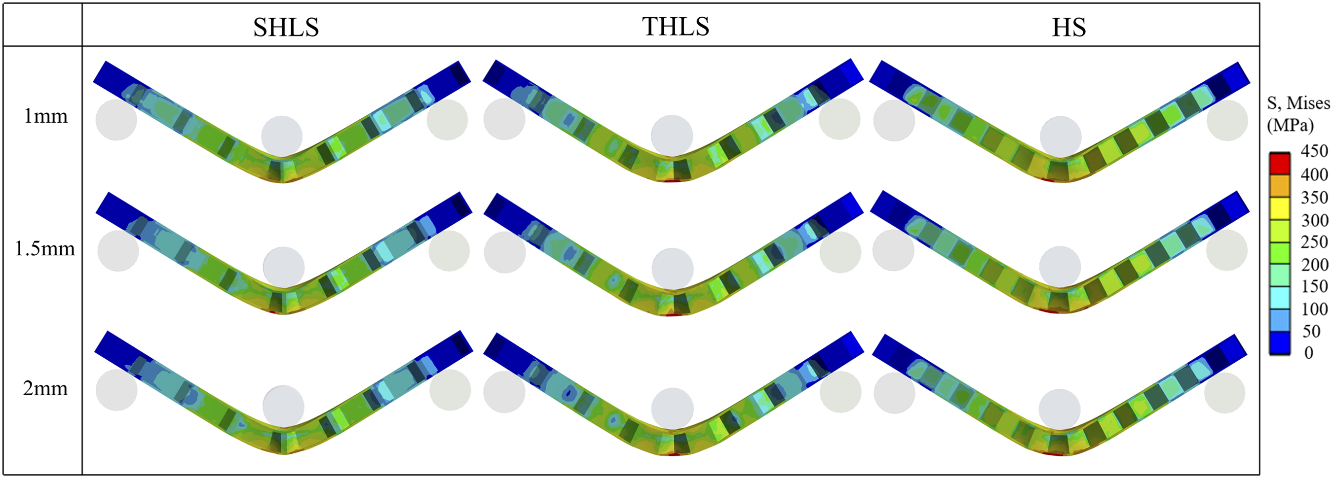
Figure 9(a) displays the load-displacement curves for three sandwich panel structures with varying core thicknesses. Under three-point bending, the load-displacement curves reveal that the core topology exerts a significant influence on the flexural response of the sandwich panels. Both load-carrying capacity and peak force exhibit a monotonic upward trend as core thickness increases across all three designs. The variation of SEA with displacement for the three structures is presented in Figure 9(b). The results indicate that SEA decreases with increasing core thickness, where SEA values decline as thickness increases. While increasing core thickness expands the deformation zone and enhances total energy absorption (EA), the mass increment significantly outpaces the EA gain. As SEA is defined as energy absorption per unit mass, the dominance of mass growth leads to a net reduction in SEA efficiency. Therefore, increasing core thickness does not necessarily improve specific energy absorption efficiency; optimal performance is often achieved within a moderate thickness range. The evaluated structures exhibit distinct energy absorption capacities: the SHLS demonstrates the highest efficiency, followed by the HS and THLS. Figure 9(c) displays the peak load for three sandwich panels with varying core thicknesses. It is observed that peak load increases with core thickness. For the SHLS, increasing the core thickness to 1.5 mm resulted in an 11% increase in peak load. When the core thickness further increases to 2 mm, the peak load increases by 17% compared to a 1 mm core thickness. This indicates that increasing the core thickness enhances the sandwich panel’s bending performance. THLS and HS also exhibit the same trend. Figure 9(d) illustrates specific stiffness trends of three core sandwich structures obtained through three-point bending tests at different core layer thicknesses. As core thickness increases, the specific stiffness of the sandwich panel structures decreases similarly to SEA, due to the rate of mass increase far exceeding the rate of stiffness increase. Differences exist in the specific stiffness among the three core structures: the SHLS exhibits the highest specific stiffness, followed by the HS, while the THLS has the lowest. The proposed SHLS achieves up to 27% higher specific stiffness compared to the THLS, and a 5% improvement over the conventional HS. Bending performance characterization of SHLS, THLS, and HS at different core thicknesses (a) Load-displacement curve; (b) SEA curve; (c) Peak load; (d) Specific stiffness.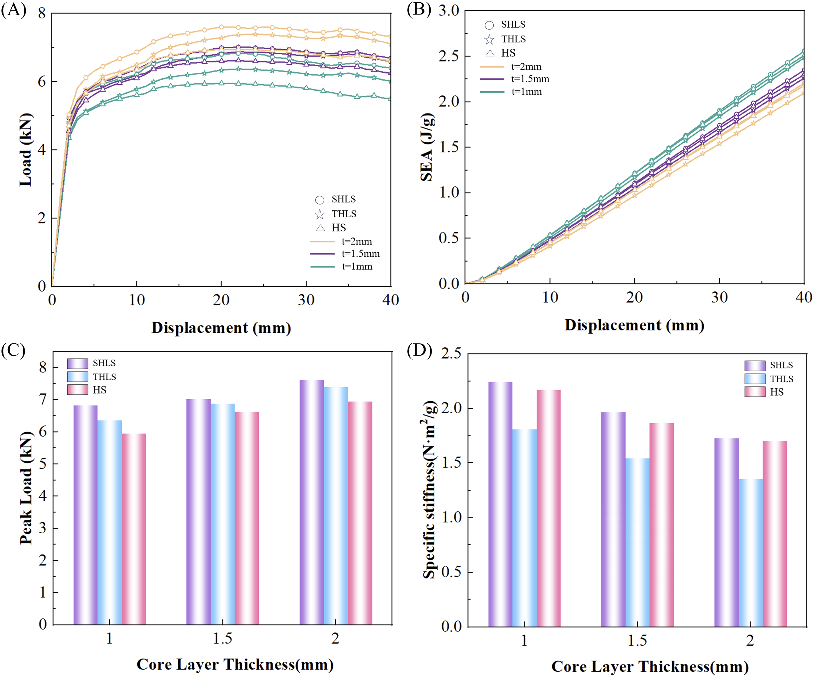
Simulation and experimental results of three-point bending for SHLS
To validate the efficacy of the proposed topology optimization and systematically evaluate the mechanical response of the SHLS under practical conditions, experimental verification was performed, aiming to characterize the mechanical properties of aluminum alloy sandwich panels fabricated via SLM through standardized three-point bending tests.
Experimental materials and specimen preparation
Material properties and experimental setup
AlSi10 Mg alloy was selected as the constituent material, the mechanical properties of which are summarized in Table 4. The dimensions of the monolithic specimens are 200 mm × 50 mm × 12 mm, incorporating 1 mm thick face sheets and a 10 mm high core layer. Three core layer thicknesses were evaluated: 1 mm, 1.5 mm, and 2 mm.
As shown in Figure 10, three-point bending tests were performed using a specialized fixture on a 50 kN MTS universal testing machine. Both the support rollers and the loading indenter had a diameter of 10 mm. A constant support span of 160 mm was maintained throughout the testing process. The tests were conducted at a constant crosshead displacement rate of 1.5 mm/min. Load-displacement data were continuously acquired and recorded via the MTS integrated sensing system. Earlier testing utilized a 20 mm indenter diameter, the validation phase unified all contact diameters to 10 mm to match high-precision laboratory test rigs and eliminate localized contact variations. Three-point bending test apparatus for sandwich panels.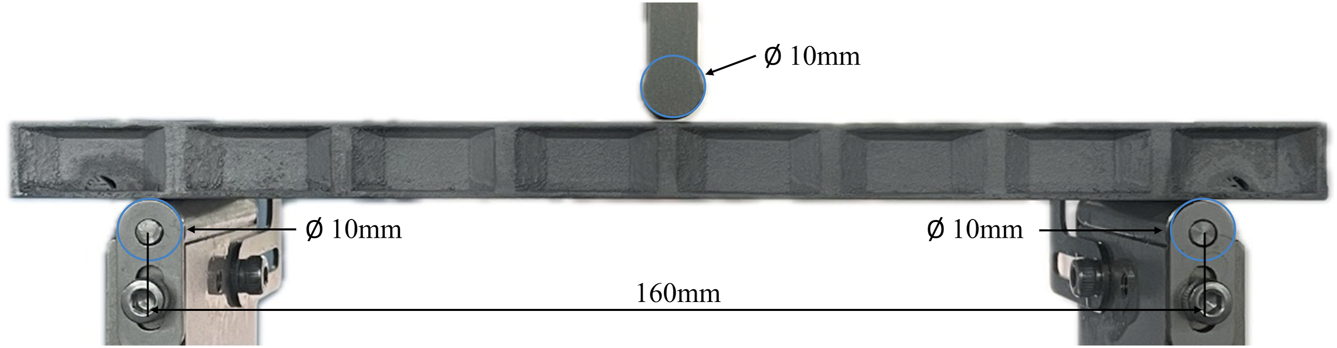
Additive manufacturing processes
This work addresses the removal of entrapped powder in monolithic additive manufacturing (AM) sandwich panels by integrating structural features with physical post-processing techniques. During the design phase, drainage orifices are strategically positioned within the core to establish continuous evacuation pathways, as exemplified by the semicircular ports at the lower corners in Figure 10. Post-fabrication, specimens are subjected to multi-axial rotation and mechanical vibration to dislodge unfused powder from the internal cavities. Subsequently, a sequence of compressed air purging and vacuum suction is applied to evacuate the internal channels, thereby minimizing residual powder.
Comparison of simulation and experimental results
Figure 11 compares the results of deformation patterns of SHLS with different core layer thicknesses in the numerical analysis with the experimental results. These results correspond to the final stage of loading immediately prior to failure. In general, the numerical simulation captures well the deformation patterns observed in the experimental tests. All sandwich structures exhibited overall bending, local indentations and fracture. Comparison of SHLS simulation and experimental results.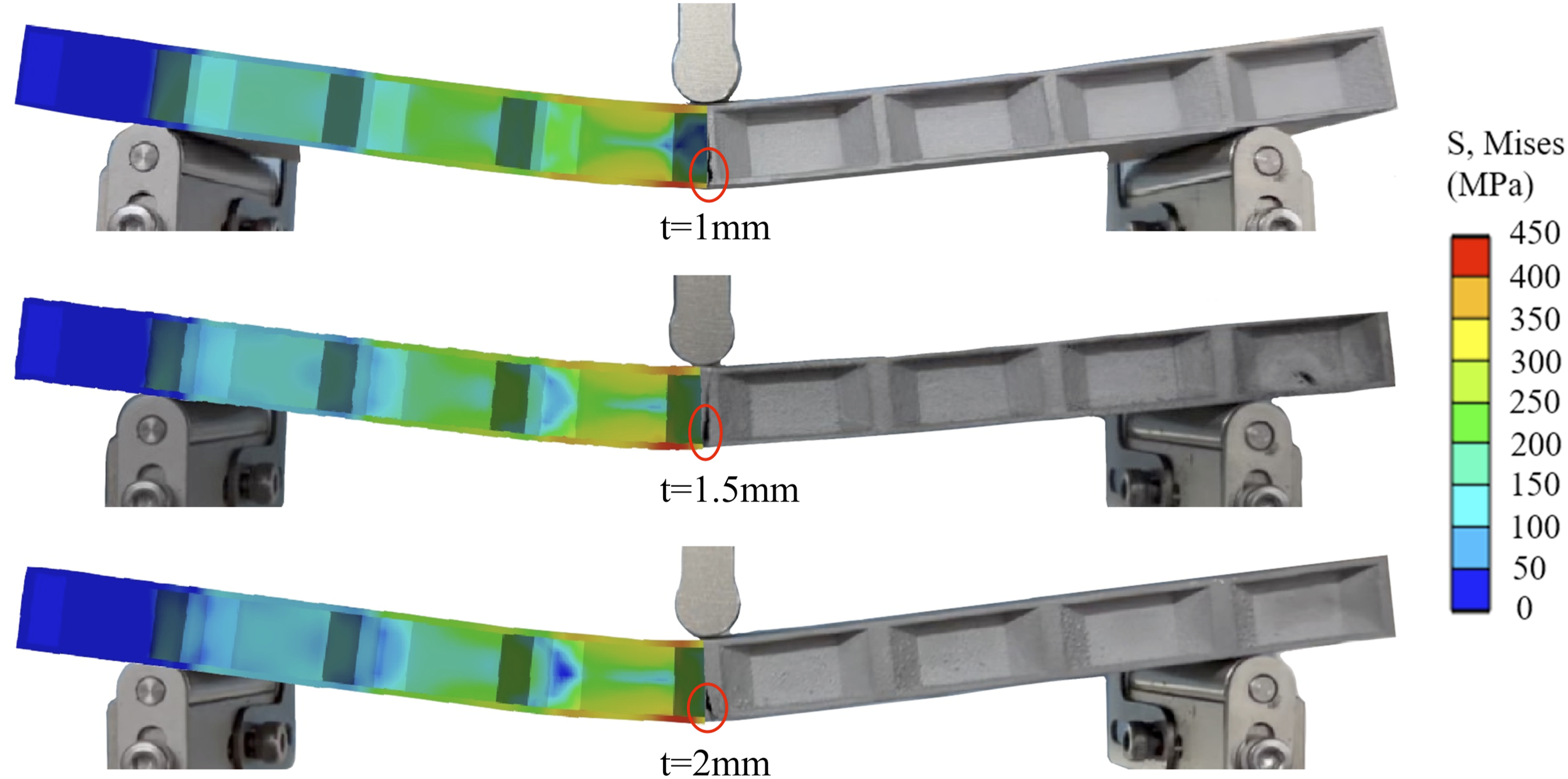
The load-displacement curves from the simulations and experiments exhibit marginal discrepancies, as shown in Figure 12(a). Across the three core thicknesses, the simulated loads are consistently slightly higher than the experimental measurements. The comparison of peak loads is shown in Figure 12(b). The peak load increases monotonically with core thickness, a trend consistent across both numerical and experimental data. The simulated peak loads are 6.71 kN, 7.21 kN, and 7.75 kN, compared to experimental values of 6.53 kN, 6.94 kN, and 7.44 kN, respectively. The comparison of specific stiffness is shown in Figure 12(c). Specific stiffness decreases with increasing core thickness because the increase in mass exceeds the corresponding gain in stiffness. The maximum error of specific stiffness between simulation and experiment is 8%. Comparison of SHLS simulation and experimental results (a) Load-displacement curve; (b) Peak load; (c) Specific stiffness.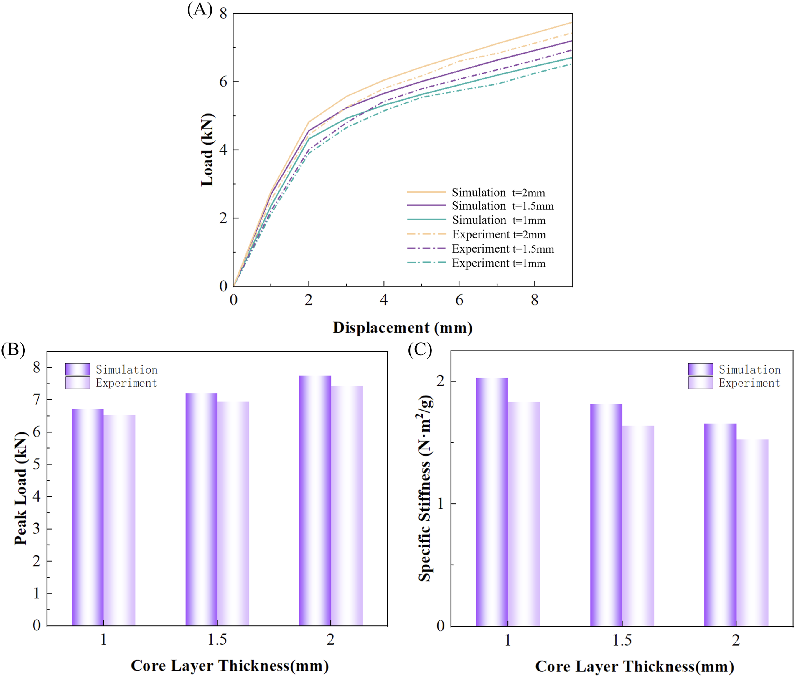
The numerical simulations achieve high predictive fidelity in capturing the experimental deformation patterns, specifically the overall bending and localized fracture mechanisms. However, minor quantitative discrepancies remain, such as an 8% maximum error in specific stiffness. These variations are primarily driven by manufacturing-induced defects. While the numerical model assumes an idealized, smooth geometry, the SLM-fabricated specimens contain inherent surface roughness and micro-porosity that act as stress concentrators, leading to lower experimental peak loads. Furthermore, despite the use of drainage orifices and vibration cleaning, trace amounts of residual powder within the SHLS core increase the physical mass, further contributing to the deviation from idealized simulation results.
Conclusion
This study develops a multi-condition topology optimization framework based on the parametric LSM to maximize the stiffness of three-dimensional sandwich panel cores. Through systematic numerical analysis, parameter sensitivity studies, and experimental verification using SLM-fabricated AlSi10 Mg specimens, the following conclusions are reached: (1) Periodic micro-topologies optimized for distinct loading scenarios exhibit substantial morphological variations and achieve peak stiffness exclusively under their specific design conditions. (2) Multi-condition topology optimization facilitates the formation of stable and continuous load-transmission paths. Although the multi-condition optimized design may not attain the absolute maximum stiffness for any individual load case, the proposed core maintains a highly balanced performance across all scenarios, thereby significantly enhancing structural robustness and adaptability. (3) Under three-point bending loads, the SHLS demonstrated measurable improvements in specific stiffness and energy absorption compared to standard benchmarks. Within the configurations evaluated, the SHLS achieved an increase in specific stiffness of approximately 27% over the THLS and 5% over standard hexagonal honeycombs. (4) The numerical models accurately predict the structural response from initial loading through to final fracture. The observed quantitative discrepancy in peak loads is primarily attributed to manufacturing-induced defects such as surface roughness, micro-porosity, and trace residual powder inherent to the SLM process.
Footnotes
Funding
The authors received no financial support for the research, authorship, and/or publication of this article.
Declaration of conflicting interests
The authors declared no potential conflicts of interest with respect to the research, authorship, and/or publication of this article.