
Abstract
A vibroacoustic study of multi-layered micro-perforated plates (MPP) coupled to an enclosure cavity excited by internal and external acoustic excitations is presented. Most previous research centered on the multi-layered MPPs structure itself, the absorption and transmission performances were often calculated or tested in a simple acoustic environment. In a more realistic setting, the surrounding systems may affect the efficiency of MPPs. The proper modeling of the MPPs within acoustic enclosures requires careful study. The break-out sound from an enclosure via multi-layered MPP and the energy transmission of the structure into an acoustic enclosure undergoing exterior excitation are studied with an emphasis on the use of MPP in acoustic enclosures to suppress specific resonances of the enclosure. Therefore, an analytical formulation is proposed to model the behavior of the coupled system to address this issue. Using a modified Fourier series for the acoustic pressure, the continuity of the normal velocities at the interfaces of the plate or the MPP and the acoustic medium is assured accurately. A modified variational form for the acoustic and structure medium yields a completely coupled vibroacoustic system. Comparison with the finite element method (FEM) and available literature findings prove the efficacy and precision of the current approach. The effect of important parameters on the vibroacoustic behavior of multi-layered MPPs structure connected to an acoustic enclosure is examined. These parameters include micro-perforation of the plate, hole diameter, air gap thickness, acoustic enclosure dimensions, and the insertion of absorbent material in the gap.
Keywords
Introduction
The interaction between multi-layered structures and acoustic enclosures is a topic of significant concern that needs to be taken into consideration in a variety of applications, including but not limited to buildings, automobiles, aircraft, and other similar areas. It is common practice to use multilayered structures for sound absorption and vibration damping. It is the purpose of these structures to enhance acoustic performance without adding extra weight, which is necessary for such applications.
Double-plates with air cavities offer superior acoustic insulation compared to single-plate structures, they are frequently used in noise control engineering. It has gained a significant amount of interest.3–9 For instance, Wang et al. 3 used the statistical energy analysis method to compute the sound transmission loss (STL) of a double panel with an air gap, while the STL of air-filled cavities in simply supported finite double panels was computed analytically by Xin et al. 4 Sandwich panels with sound-absorbing cores have also been the focus of a significant number of studies in addition to air cavities.1,2,10–17 For example, Bolton et al.12,15 applied the Biot theory to compute the STL of double-plate configurations filled with an elastic porous material. Doutres and Atalla 11 suggested an approach to compute the transmission loss of a double-plate structure with layered blanket cores. Specifically, it was discovered that at structural resonance frequencies, STL is enhanced with sound-absorbing cores. Santoni et al. 18 published a review of the various methods to predict the sound transmission loss of building partitions.
On the other hand, MPPs are excellent sound absorbers. Perforated panels were placed in front of a solid wall to accelerate particle velocity through the perforations and dissipate acoustic energy. Without adding a layer of porous materials, sub-millimeter-sized holes may offer relatively wide-band absorbers due to the shear forces induced by the vibration of the air moving through them. That allows the construction of absorbent walls that are lightweight, fiber-free, and highly functional. Numerous researchers have investigated, both theoretically and experimentally, MPPs' effectiveness as sound absorbers. Maa19,20 first presented a model approach for the sound absorption coefficient (SAC) of MPPs using an electroacoustic analogy. Using rigid-frame porous material models, the SAC of MPPs was calculated by Atalla and Sgard. 21 Ng and Hao-MING 22 investigated the effectiveness of perforated honeycomb sandwich panels as sound absorbers for low-frequency range. It has been demonstrated that the configuration is capable to absorb sound for frequencies as low as 63 Hz. The SAC of MPPs was estimated using an empirical impedance model by Rao and Munjal 23 and Lee and Kwon. 24 Yuvaraj and Jeyanthi 25 examined a countersunk MPP and two layers of porous materials in an impedance tube. The device improves sound absorption, and porous materials extend its bandwidth. Although MPPs perform well as sound absorbers, they are inadequate for STL. When compared to a plate of the same thickness, the STL of an MPP is lower as shown by Chen 26 and Dupont et al. 27
Currently, researchers are now considering MPP and sandwich panel combinations for STL and SAC. Perforated sandwich panel face plates can absorb sound, while back plates can function as noise barriers. The acoustic performance of an MPP-air cavity-plate coupled system was initially analyzed analytically and experimentally by Dupont et al. 27 It was discovered that the STL could be increased with a good SAC. Honeycomb structures were inserted into the air cavity of the system by Toyoda and Takahashi 28 to enhance the STL at medium frequencies. To compute the absorption and transmission properties of multi-layered MPPs separated from a thin plate by an air gap, Bravo et al.29,30 suggested using a fully coupled analysis model for the calculation of the SAC and STL. Airframe and MPP-back panel relative velocities were shown to control the SAC and STL at acoustical resonant frequencies. Mu et al. 31 found that adding an MPP to the source as well as the transmitting face of the double-panel improved the mass-air-mass resonance. Using the transfer matrix technique, Kim et al. 32 described in good detail the effects of micro-perforations on multi-layered infinite MPPs’ STL over the whole frequency range. The equivalent impedance, which is the combination of the impedances for the inertia term and the micro-perforation, was used to characterize the effect of the perforation. Employing the transfer matrix approach and assuming a condition of plane waves in the low-frequency domain, Kim et al. 33 analyzed multi-layered flexible MPP’s STL, placed in a rectangular cross-sectioned impedance tube, with emphasis on its behavior at resonance frequencies.
In most of these investigations, the absorption and transmission properties of multi-layered structures were evaluated without considering the influence of the surrounding system. Numerous studies on the cavity-plate systems excited by internal or external noise sources which may be airborne or structure-borne and their vibroacoustic behaviors have been published. By using modal coupling analysis, Pan 34 demonstrated how to calculate the acoustic and vibrational fields in a coupled plate cavity. Calculations were done to determine the frequency response as well as the sound field's transient decay in the cavity. The transmission of energy from a double plate connected by a mechanical link partition into an acoustic cavity was studied by Cheng et al. 35 The influence of the air gap and mechanical links on the soundproofing and insulation characteristics of these structures was explored using a fully coupled vibroacoustic formulation. Through the application of a secondary force, Pan et al. 36 and Pan and Hansen 37 suggested active sound transmission control into a cavity through a panel. Bravo and Elliott 38 developed a coupled analytical method to examine cavity-panel-cavity and cavity-panel problems and the variability of the sound transmission loss in the low-frequency range was discussed. The impedance-mobility approach39,40 was employed to investigate the break-out of sound from a rectangular enclosure with a plate(s). The pressure distribution as well as the radiation pattern of a structural-acoustic coupling system composed of a cavity and a semi-infinite space separated by a wall were predicted by Seo and Kim. 41 Using the finite element analysis, Becot and Sgard 42 investigated the capability of poroelastic materials to control the noise radiated outside a cavity in the low-frequency range. Attaching poroelastic to a panel, a considerable reduction in board frequency range can be achieved. The acoustic cavity delimited by a flexible and holed structure was the subject of research by Kim and Kim.43,44 It was demonstrated that, based on the frequency range and wave number, the cavity can effectively communicate with the surrounding environment via the vibrating structural system and the hole. Clasen and Langer 45 used a two-dimensional FEM model to predict flanking transmissions in building acoustics. Through the use of a modified Fourier series approach, Du et al.46,47 analyzed the cavity-panel system, reinforcing full velocity continuity at the cavity/panel interface. Using the patch-mobility technique, Chazot and Guyader 6 predicted the transmission loss of a double panel coupled to a source room. To further investigate the transmission loss of a double panel filled with poro-granular material using the fluid-fluid Biot's model, the authors extend their previous paper. 10 Wang et al. 48 presented a method for estimating the break-out sound from an acoustic cavity-backed plate. The model considers the interface’s strong structural-acoustic couplings. However, few studies focused on MPP coupled to an acoustic cavity. Sound absorption of MPPs supported by air volume or honeycomb structure was studied by Yang and Cheng 49 in small enclosures. Backing cavity and enclosure interaction were found to have a significant impact on the MPP’s capacity to absorb sound. However, the analytical model used in these studies consists of a typical MPP and a rigid back wall coupled to an acoustic enclosure. Thomazelli and Bertoli 50 investigated a potential alternative to optimize the production and development of a tunable MPP absorber capable of changing its geometrical configurations in response to the acoustic requirements of each room.
However, none of the prior research examined the vibroacoustic behavior of a multi-layered MPP structure coupled with an acoustic enclosure. In building acoustic problems, multi-layered MPPs might be utilized to minimize external noise transmitted to the acoustic enclosure. The structure might also be utilized to reduce reflections and transmissions produced by internal noise sources. Multi-layered MPP behavior must be evaluated in such applications by considering the interaction with acoustic enclosures. Existing research has significant limitations: (a) The sound transmission and absorption properties of multi-layered MPPs were evaluated without considering the influence of the surrounding system. Nonetheless, the surrounding systems and excitations have a significant impact on the multi-layered MPP's performance, and (b) most of the studies of cavity panel systems assume an external sound source or internal sound source, and researchers are focused on determining the cavity pressure and the sound transmission loss related with the configuration. However, the use of microperforated plates to introduce damping in a closed cavity and reduce reflections has not been examined. It is essential to model and predict the multilayered MPP's effectiveness in a complex vibro-acoustic environment to have a thorough understanding of vibro-acoustic behavior and how it responds to changes in the various system variables. Furthermore, the development of a strong and precise strategy capable of generically addressing numerous system aspects would be of tremendous value to both academics and engineers. To the author's knowledge, despite the progress achieved previously, the in-situ behavior of multilayered MPPs in a strongly coupled vibroacoustic system has never been systematically reported in the literature.
Intending to address the aforementioned shortcomings of previous models and clarify the vibroacoustic behavior of the multi-layered MPP and its sensitivity to changes in any of the system variables, a general structural-acoustic coupling model of a simply supported MPP separated from a plate by an air gap and coupled to an acoustic enclosure is presented. A vibro-acoustic formulation is proposed to model the behavior of the coupled system. A modified Fourier series is used to describe the sound pressure inside the cavity. The displacement and acoustic pressure solutions are obtained using the modified variational principle for the coupled system. Comparisons with the finite element technique (FEM) and previously published results provide evidence of the present approach's efficiency and accuracy. The effect of critical factors on the STL of the structure coupled to an enclosure is investigated, including micro-perforation of the plate, hole diameter, air gap thickness, acoustic enclosure dimensions, and the influence of absorbent material installed in the gap. It should be highlighted that the present approach is readily extensible to multi-layered MPPs coupled with an acoustic enclosure.
Theoretical formulations
Description of the coupled system
Figure 1 depicts the coupled system that is the subject of the current investigation. This system is an outer plate and an inner micro-perforated plate separated by an air gap Vg and coupled to an enclosure cavity. The MPP and the plate are rectangular, homogeneous, and isotropic. The simply supported boundary condition for the MPP and the plate is assumed. The following two cases are examined. A uniform, oblique plane sound wave with an incidence elevation angle
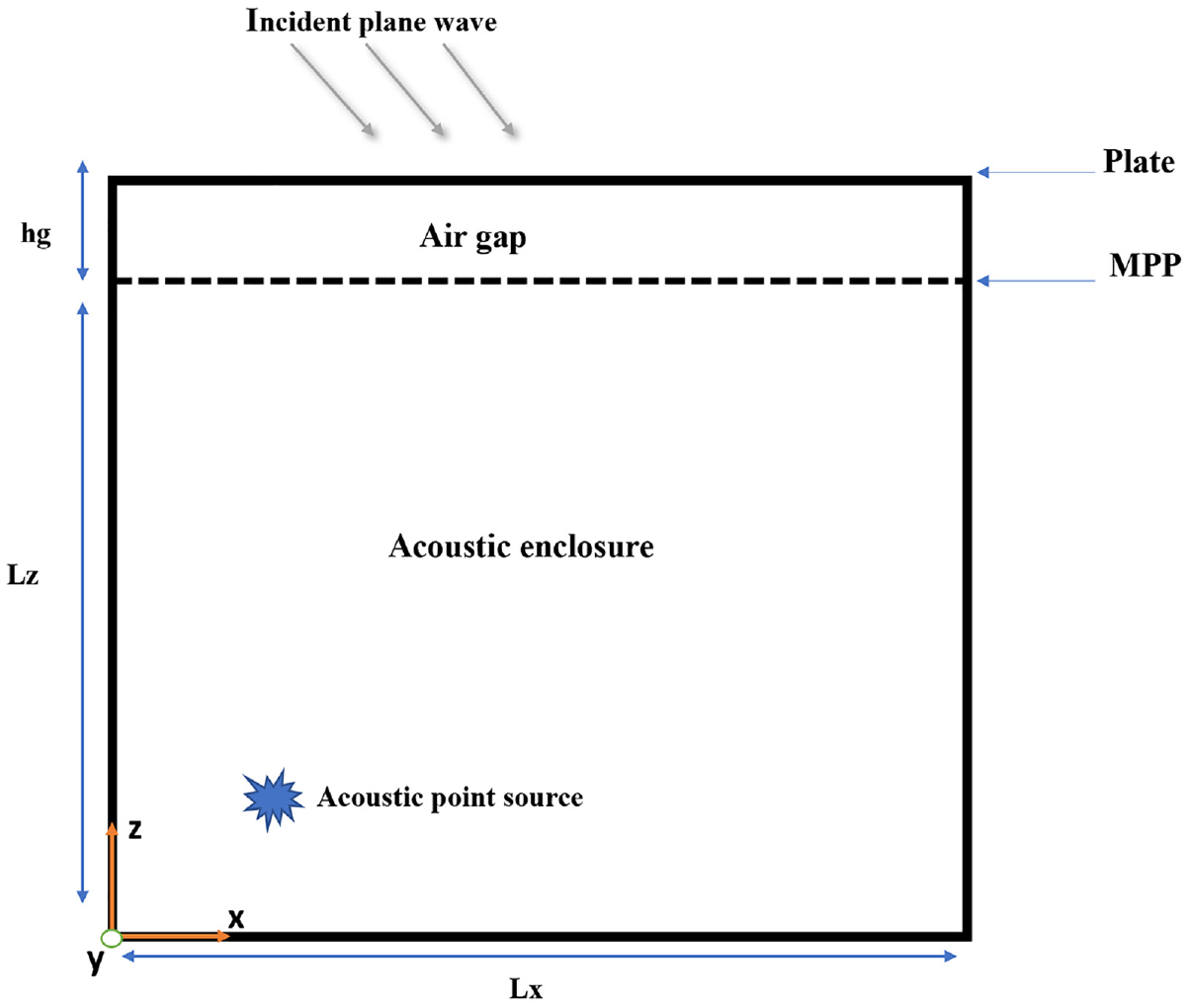
A schematic of an MPP-Cavity-Plate structure coupled to an enclosure.
The acoustic pressure within the acoustic enclosure should satisfy both the wave equation and the corresponding boundary conditions.
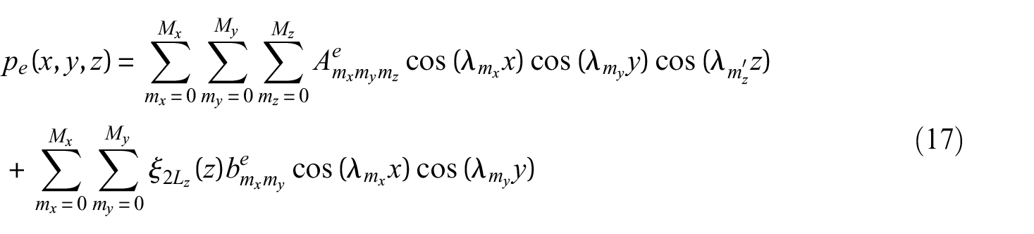
The wave equation is given as:

Where

Where
The boundary conditions on the enclosure boundaries:


where
Similarly, the acoustic pressure within the air gap satisfies the wave equation including the continuity conditions on the boundaries:


Where
As can be seen in Figure 2, the average velocity

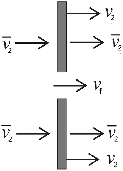
Average velocity on the surface of the MPP.
As was shown in prior research, 51 the impedance of the MPP is related to the pressure difference.

According to Maa,
20
the impedance of the hole,

where
The elimination of the term

Where,

In the absence of perforation,
The governing equation of the outer plate is given as a function of the plate displacement

Where

In equation (12), damping of the structure is taken into consideration by inserting a complex Young’s modulus
The sound pressure exerted on the incident panel is a combination of three different pressures: the incident pressure, the reflected pressure, and the radiated pressure which is extremely insignificant. Because the impedance of the incident plate is comparable to that of a rigid boundary when subjected to air loading, it is safe to assume that the magnitudes of the incident and reflected pressure waves are the same.35,52,53 Therefore, by ignoring the pressure radiated toward the outside, we can determine that the blocked pressure, also known as the excitation pressure, is twice as great as the magnitude of the incident wave 53 :

where
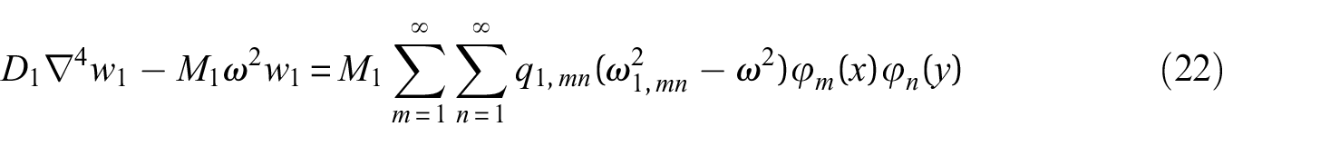
Similarly, the governing equation of the inner MPP is given as a function of MPP displacement

Where
Solution procedure of the coupled system
The velocity,

Where
For the case of simply supported boundary conditions,
To ensure differential continuity at the structural-acoustic coupling interface, the acoustic pressure inside the enclosure and the air gap may be represented as.46,47
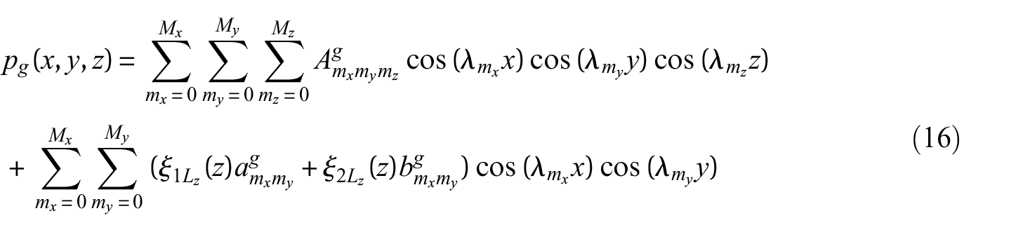
Where
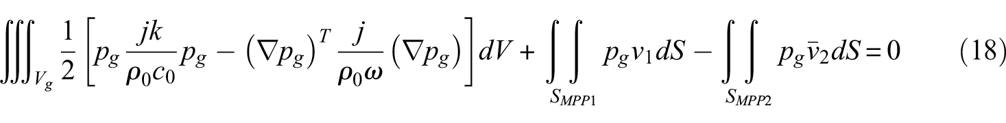
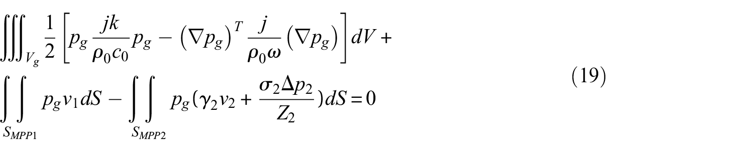
Theoretically, an acoustic analysis of an enclosure may be expressed in a variational form. This can lead to a solution that is preferable to the one that can be obtained by just solving the Helmholtz equation. To accomplish this goal, a modified variational approach54–56 is used to define the distribution of the acoustic pressure. This method involves searching for the minimum of the associated modified variational function.
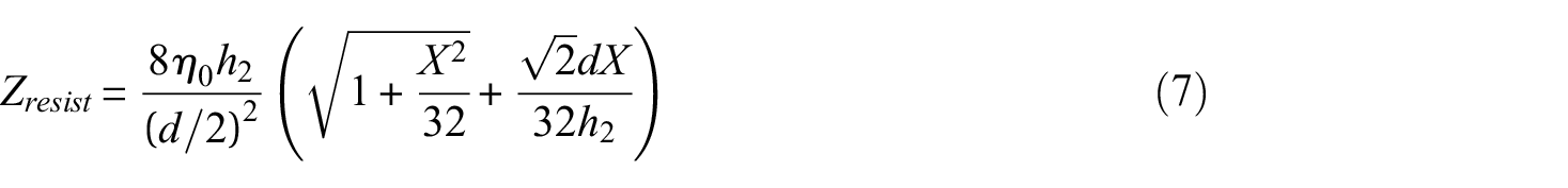
Using equation (7) we get
Where
The characteristic equation may be found by inserting the admissible function specified in equations (15)–(17) into equation (18), and then carrying out the variational operation in terms of the generalized coordinate vector.
The resultant matrix equation for the air gap is as follows:

In the same manner, for the acoustic enclosure, we get:

Using equation (15), the left-hand side of equation (11) can be rewritten as
Where
When both sides of equation (11) are multiplied by
Following the same steps for the MPP, we get:
The enclosure and air gap equations (20) and (21) and the MPPs equations (24) and (25) form a set

where
It should be noted that the formulated equations are restricted to the case of plate-cavity-MPP coupled to an acoustic enclosure. However, it could be easily extended to multilayered MPPs-Cavity-Plate coupled with an acoustic enclosure.
Calculation of the transmission loss
Transmission loss in the case of an enclosure as receiving room
The transmission loss or sound reduction index of an MPP-Cavity-Plate partition is defined by the following relation:

Where
where
Transmission loss in the case of an enclosure as a source room
The transmission loss of the partition is defined by the relation:

where

Where
The radiation power can be determined from the relation below:

Where
Numerical results and discussions
In this section, the proposed model is validated and a parametric study is performed following the theoretical modeling and solution approach presented previously. The equations derived in earlier sections have been incorporated into a computer program. The current method for estimating the dynamical responses and the STL of the MPP-Cavity-Plate structure connected to an enclosure in both cases, internal acoustic point source and external plane wave, will be validated first to verify its reliability and accuracy. Then, an investigation into the effects of different significant parameters on the vibroacoustic behavior of the coupled system is carried out, including micro-perforation of the plate, hole diameter, air gap thickness, acoustic enclosure dimensions, and the influence of absorbent material introduced in the gap.
Model validation
Numerical validation
This section gives analytical and numerical comparisons to verify the accuracy and precision of the current method. For this purpose, an MPP separated from a flexible plate by an air gap and connected to an enclosure is simulated, and the results obtained using the proposed method are compared to those predicted using finite element analysis software (Comsol). The coupled system considered consists of simply supported MPP and plate (
To verify the efficiency of the proposed model for acoustic source inside the enclosure. A point source of strength
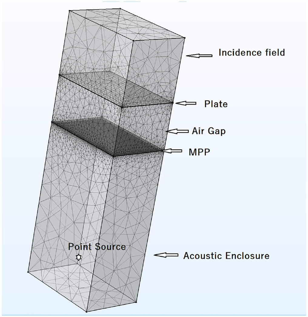
Finite element model of an MPP-Cavity-Plate coupled to an acoustic enclosure.
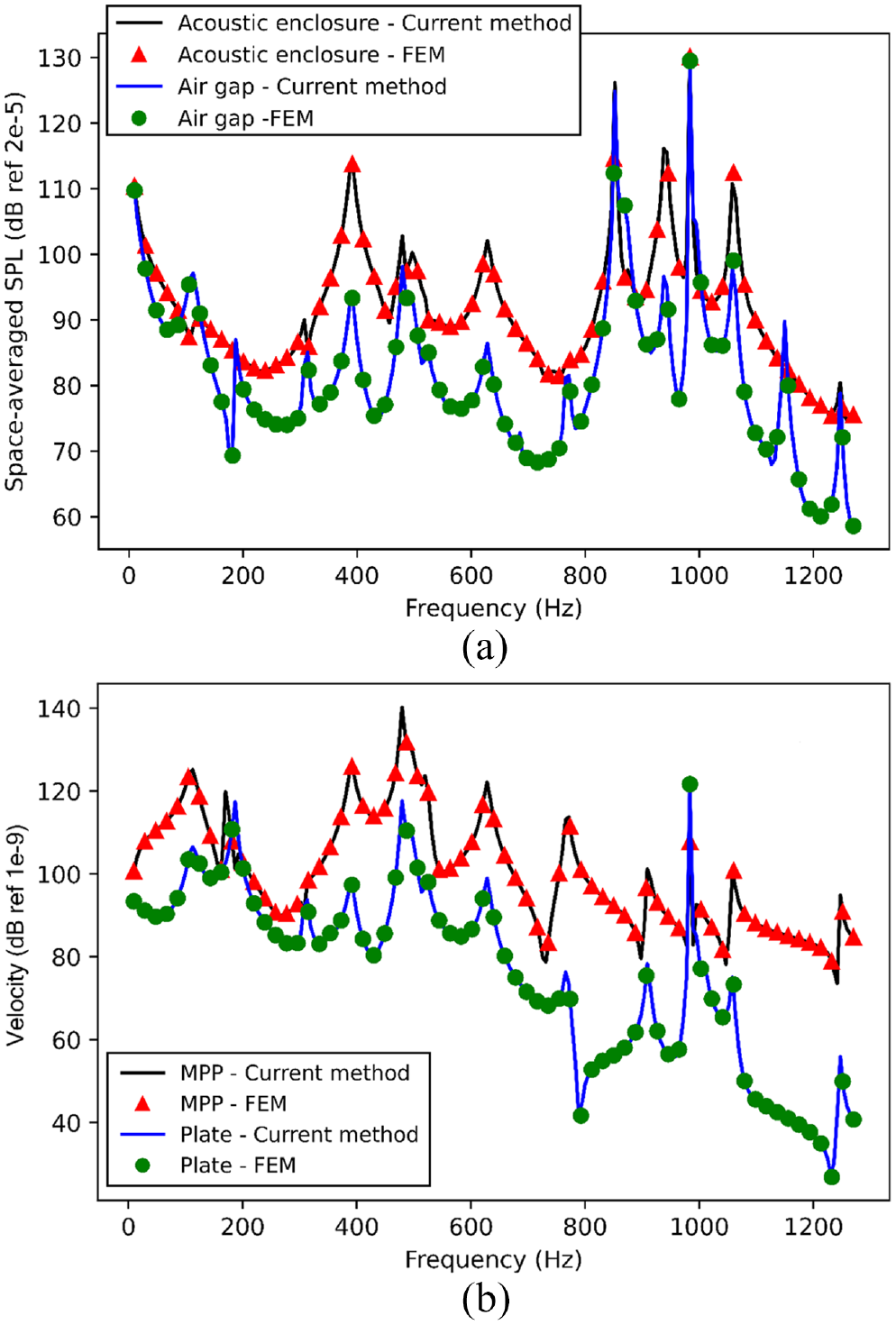
Comparison of the current method and FEM numerical method on predicting the velocity responses on the MPP (0.1, 0.1, 0) and the panel (0.1, 0.1, 0) and the space-averaged sound pressure inside the acoustic cavity and air gap when the coupled system is excited from inside by an acoustic point source.
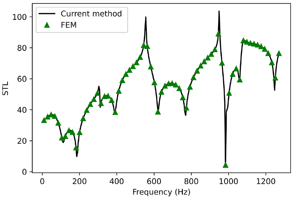
Comparison of calculated STLs using the present approach and FEM results for MPP-Cavity-Plate coupled to an acoustic enclosure when excited from outside by a plane wave.
Comparison with finite-sized partitions in free field
Comparisons are made between the predicted TL when multi-layered MPP partitions are coupled to an acoustic enclosure with those previously published in the literature.
29
In this selected study, Bravo et al investigated the propagation of two-dimensional plane waves over an insulating partition set in an acoustically rigid stiffened baffle with finite size
Figures 6 and 7 display the findings for the TL assuming internal source (acoustic point source) and external source (incident plane wave), respectively. Comparing these findings to those of an MPP-Cavity-Plate partition set in an acoustically rigid stiffened baffle reveals that the agreement is excellent. The proposed approach, when the partition is connected to an acoustic enclosure, can accurately anticipate the overall trend for the TL across a wide frequency spectrum. It provides further details on the modal effects of an acoustic enclosure on power transmission due to the presence of acoustic resonances. The STL dips corresponding to structural resonances in the simply supported case are shifted to lower frequencies in comparison with those of the clamped case, 29 this can be explained by the fact that the natural frequencies of the simply supported system are lower than their counterparts of the clamped system.
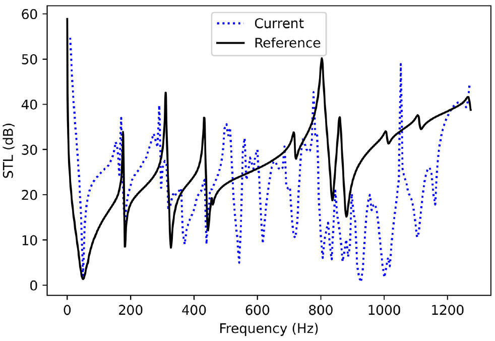
STL of MPP-Cavity-Plate coupled to an acoustic enclosure when excited from the inside (acoustic point source) and configuration of Bravo et al. 29
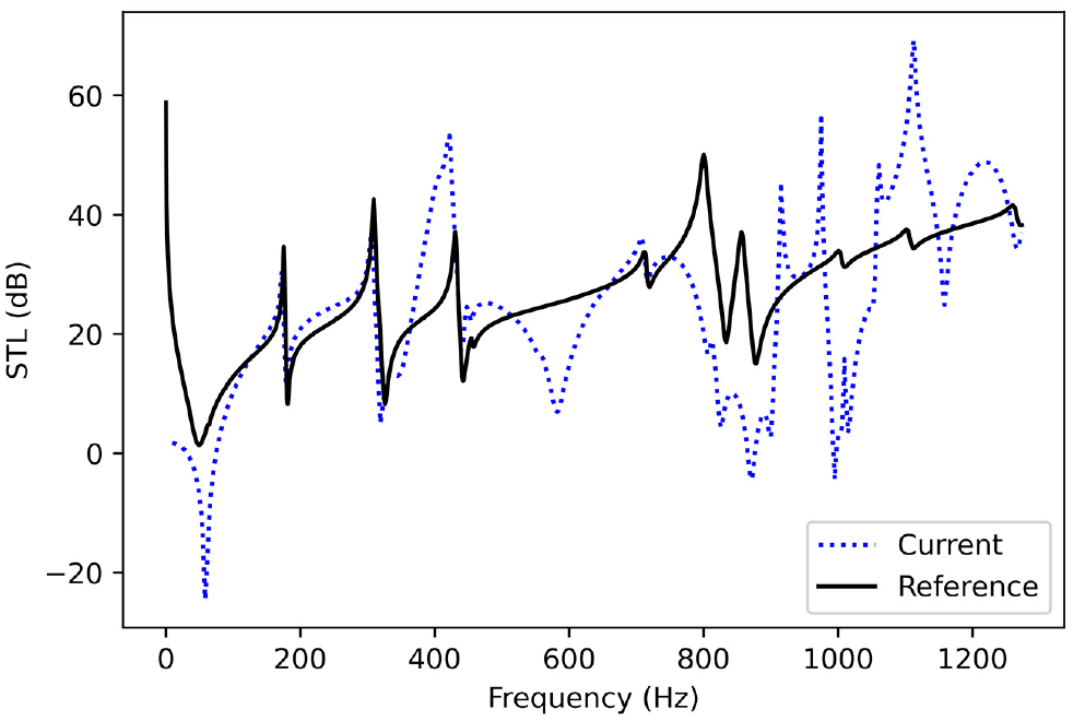
STL for MPP-Cavity-Plate coupled to an acoustic enclosure when excited from the outside by plane wave and configuration of Bravo et al. 29
Parametric study
Several major system parameters that impact the vibroacoustic behavior/acoustic performance of the MPP-Cavity-Plate structure coupled to an acoustic enclosure are investigated by employing numerical modeling. In numerical simulations, the connected enclosure’s dimensions and properties are specified as follows. The dimension of the enclosure is
Effect of micro-perforation of the MPP
To examine the impact of the perforation ratio on the coupled system, the STLs for both cases, external acoustic excitation (plane wave) and internal acoustic excitation (acoustic point source), are plotted considering different perforation ratio values. As seen in Figures 8 and 9, as the micro-perforation ratios grow, the STLs deteriorate. Comparison between the case of the double plate (
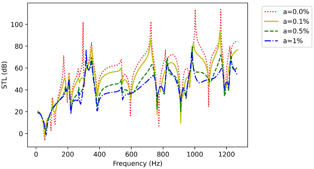
STL of the partition when the coupled system is excited from outside for various perforation ratios.
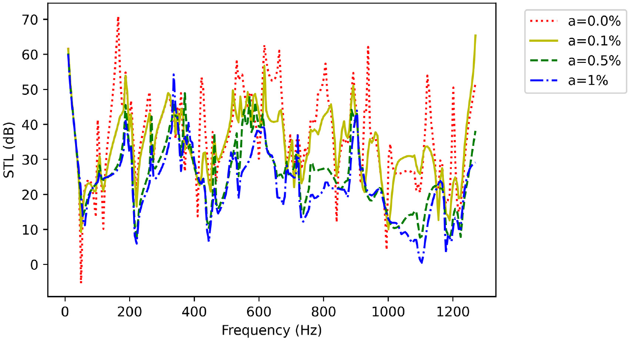
STL of the partition when the coupled system is excited from inside for various perforation ratios.
From the plot of the space-averaged sound pressure level for different perforation ratios (Figure 10), It can be seen that almost all of the resonances of the acoustic enclosure are damped when the micro-perforation is increased. This is because the MPP introduces modal damping into the system. Additionally, frequency shifts are seen at some peaks that are attributed to the reactance term of the impedance of the MPP. It should be noted that when the inner plate is not perforated, No damping or shifting has occurred at these peaks. This can be explained by the fact that the increase in perforation improves both absorption bandwidth and absorption amplitude as shown in the plot of the computed absorption coefficients of MPP-Cavity-Plate in free field conditions using the proposed method in Bravo et al. 29 in Figure 11.
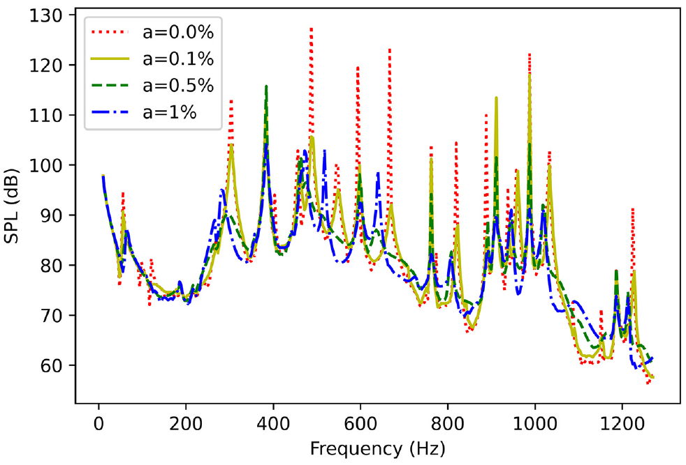
Space averaged SPL inside the enclosure when the coupled system is excited from inside for various perforation ratios.
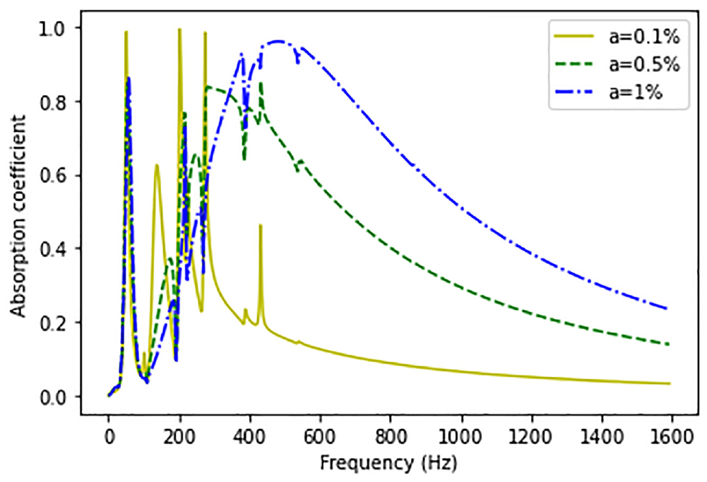
Comparison of the absorption coefficients of MPP-Cavity-Plate for three different perforation ratios of the MPP.
Effect of the hole diameter
In this section, the pore diameter is varied while the perforation ratio on the MPP is kept constant and equal
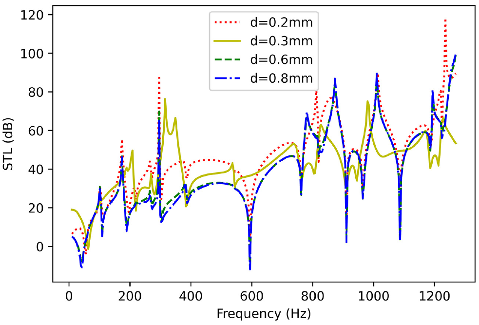
STL of the partition when the coupled system is excited from outside for varying micro-pore diameter.
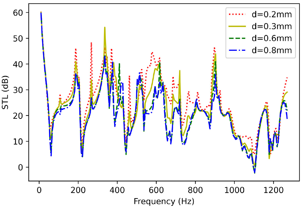
STL of the partition when the coupled system is excited from inside for varying micro-pore diameter.
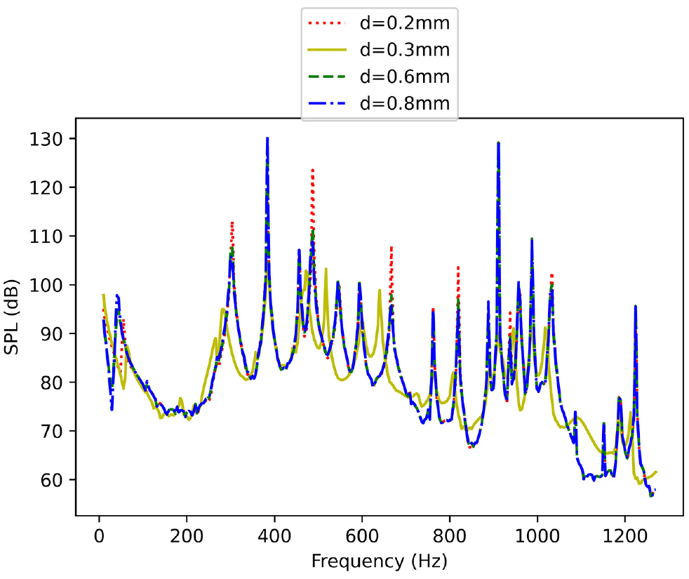
SPL inside the enclosure when the coupled system is excited from inside for varying micro-pore diameter.
Effect of the air gap thickness
To determine the impacts of air gap depth on STL, a series of numerical computations with variable air gap thickness are performed. The influence of air gap depth (
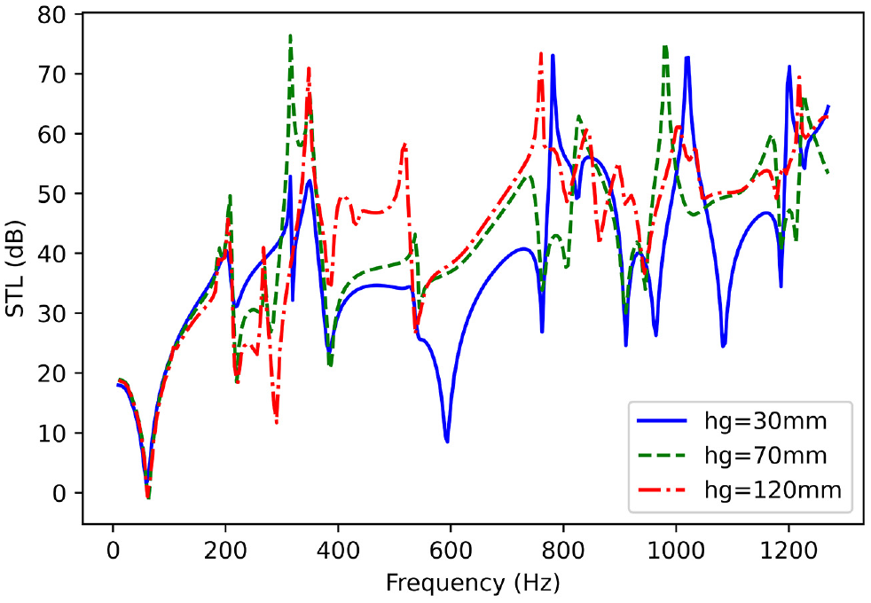
Influence of air gap on STL of the partition when the coupled system is excited from outside.
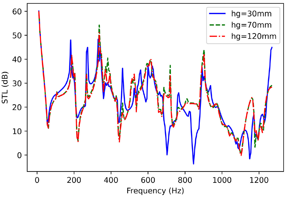
Influence of air gap on STL of the partition when the coupled system is excited from inside for micro-pore diameter.
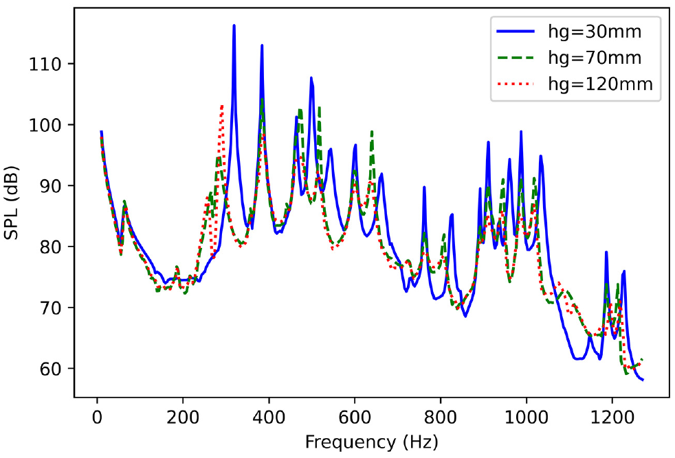
Influence of air gap on SPL inside the enclosure when the coupled system is excited from inside.
Effect of acoustic enclosure dimensions on STL
To determine the modal effects of the enclosure on STL, a series of numerical simulations with varied
Figures 18 and 19 depict the associated transmission loss for both cases for two different MPP’s perforation ratios (
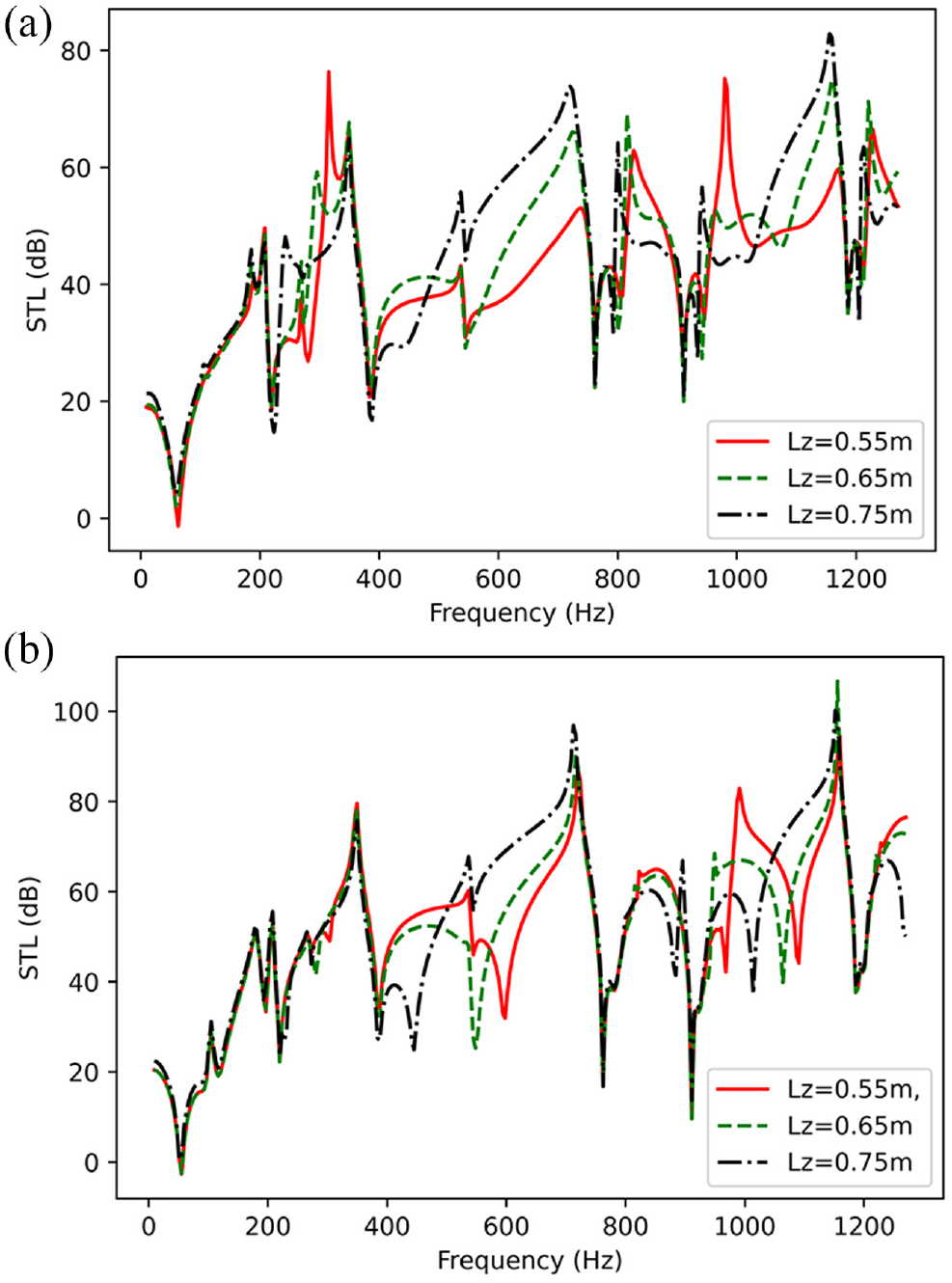
STL of the partition when the coupled system is excited from outside for different dimensions of the enclosure: (a) a = 1% and (b) a = 0.1%
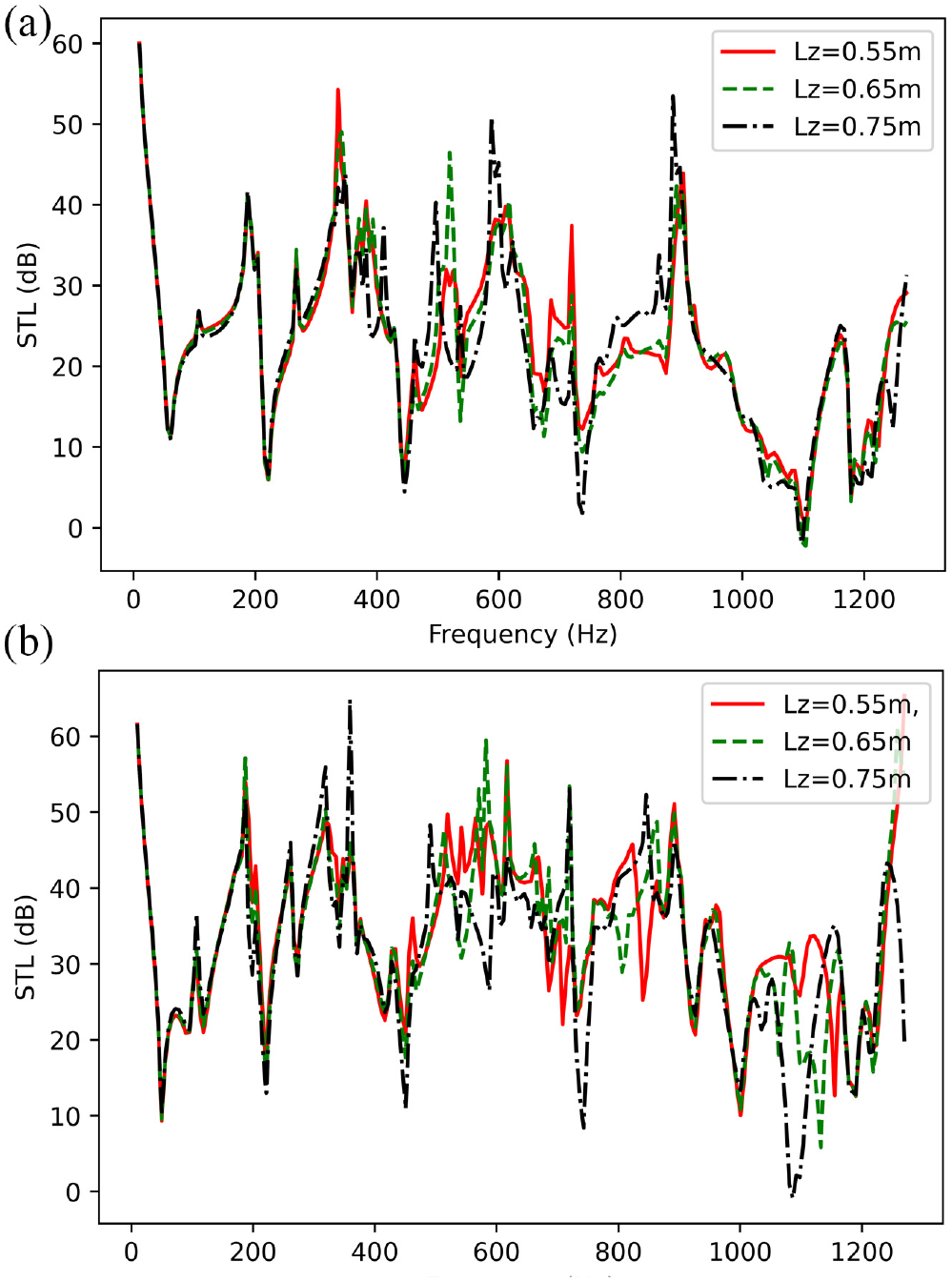
STL of the partition when the coupled system is excited from inside for different dimensions of the enclosure.
Enclosures have a significant impact on the STL of multi-layered MPPs structures. Therefore, the transmission loss of multi-layered MPP coupled to an acoustic enclosure must be thoroughly examined. In general, changes to the depth of the enclosure have the largest effect on the acoustical natural frequencies, although the effect on the plates is negligible.
Influence of porous material
To improve the transmission loss at resonant frequencies, sound-absorbing material with flow resistivity
Figures 20 and 21 compare the computational results of a gap filled with fiberglass vs air. It is observed that the transmission loss increases above 500 Hz. At the resonances, however, a large gain is gained in both transmission loss in the two cases and sound pressure level peaks inside the acoustic enclosure plotted in Figure 22. The damping introduced by the absorbent material governs the response of the system. The damping is mostly attributable to the acoustic dissipation generated by viscous drag forces and thermal exchanges between the air and the material.
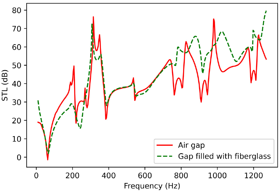
STL of the partition when the coupled system is excited from outside for gap filled with fiberglass and gap filled with Air. The perforation ratio of the MPP is
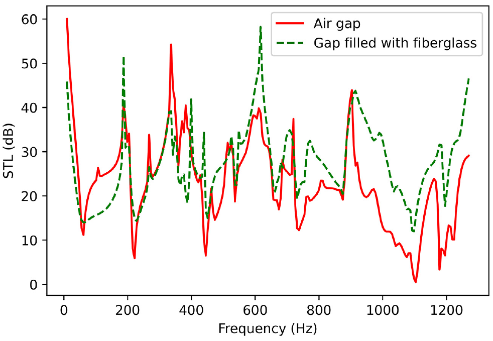
STL of the partition when the coupled system is excited from inside for gap filled with fiberglass and gap filled with Air.
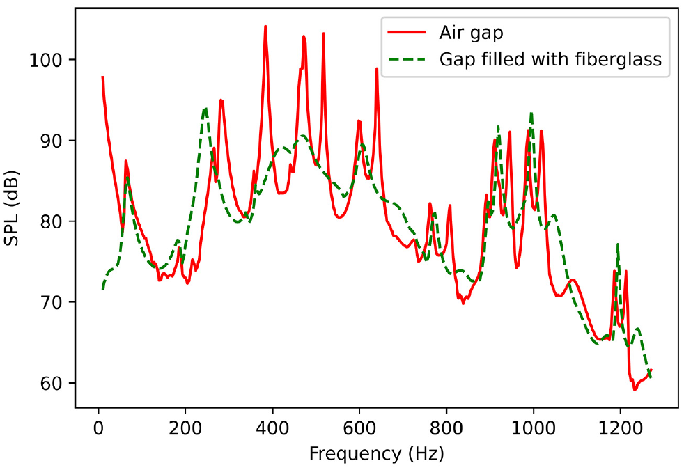
SPL inside the enclosure when the coupled system is excited from inside for gap filled with fiberglass and gap filled with Air.
Conclusion
This study presents the results of a vibro-acoustic investigation of a multi-layered MPP structure coupled to an enclosure. The transmission loss of the structure was predicted using an analytical method. Using a modified variational model, the equations of the coupled system were derived. The 3D-enhanced Fourier series describes the acoustic pressure inside the air gap and the enclosure. MPPs are assumed to have the simply supported boundary condition. In addition, finite element computation demonstrates the validity and accuracy of the present model, with a great agreement being achieved. Then, a parametric investigation was conducted to determine the influence of micro-perforation of the plate, hole diameter, air gap thickness, acoustic enclosure dimensions, and the insertion of absorbent material in the gap on the vibroacoustic behavior of the coupled system
The results summarized here are the most significant: As anticipated, the STLs deteriorate with the increase of the micro-perforation ratio of the MPP. However, the dips in the STL corresponding to the resonances of the acoustic enclosure are damped. Regarding the sound pressure level inside the enclosure, the acoustic resonances are damped due to the modal damping introduced by the MPP. It is found that the STLs are improved at the resonant frequencies as the hole diameter decreases and the resonant frequencies are damped until an optimal value for the given parameters of the coupled system. In addition, by increasing the micro-pore diameter the peaks of the pressure inside the enclosure are damped and shifted due to the reactance term of the MPP. It was also discovered that the STL values rise as the thickness of the air gap grows, but the locations of coupled system resonances (dips) stay generally unaltered. In addition, the air gap thickness influences the damping of the resonance peaks of the SPL of the enclosure by shifting the absorption bandwidth. It has been shown that the introduction of an acoustic cavity may have a considerable influence on the vibro-acoustic behavior of the structure, resulting in additional dips corresponding to the excited acoustic modes only when the perforation ratio is small. Moreover, when absorbent material is inserted into the gap, transmission loss increases, particularly at the resonances, and the peaks of the sound pressure are damped.
The presence of an acoustic enclosure can result in a significant impact on the vibro-acoustic behavior of multi-layered MPPs structures, which might provide essential information for the design process and noise reduction of these structures. In comparison to prior techniques, it is easier to establish different structural and acoustic boundary conditions. In addition, the suggested approach may be immediately applied to other, more realistically complex geometries. Currently, additional research is being conducted to assess the applicability of heterogeneous MPPs for the same objective. For example, it has been demonstrated that the concept of inhomogeneous perforation can significantly increase bandwidth absorption at a low-frequency range when the effect is evaluated in an impedance tube. It is still necessary to quantify their performance after it has been incorporated into a more complex system. Future studies will also look into their transmission efficiency when coupled to an elastic structure and the factors underlying in this process.
Footnotes
Declaration of conflicting interests
The author(s) declared no potential conflicts of interest with respect to the research, authorship, and/or publication of this article.
Funding
The author(s) received no financial support for the research, authorship, and/or publication of this article.