
Abstract
Accurate prediction of heavy-weight floor impact sound in concrete apartments is essential for minimizing residents’ exposure to low-frequency noise, which can significantly affect health and quality of life. This study investigates an improved finite element analysis (FEA) modeling approach by accurately reproducing the dynamic stiffness of resilient materials in floating floor systems. The elastic modulus and dynamic stiffness of four types of resilient materials were experimentally measured using a universal testing machine (UTM) and ISO 9052-1 testing methods, respectively. These values were then used in an FEA model developed in COMSOL Multi-physics. The results demonstrated that conventional input methods, where the elastic modulus is obtained by multiplying the measured dynamic stiffness by material thickness, led to an overestimation of 175.2% compared to the actual measured values. To improve accuracy, a correction factor was derived, adjusting the input elastic modulus to 60%–66% of the measured dynamic stiffness multiplied by thickness, which reduced prediction errors to within 0.6 MN/m3. When applied to heavy-weight floor impact sound prediction in actual apartment buildings, this method improved prediction accuracy by up to 48.1% (RMSE criterion) compared to conventional approaches. These findings highlight the importance of accurately defining material properties in FEA simulations for floating floor systems to prevent low-frequency amplification effects and optimize sound insulation performance.
Keywords
Introduction
With industrialization and urbanization, population density has increased in specific regions, leading to a widespread adoption of vertical residential structures in cities to address this issue. In such vertical housing, the floor of an upper unit simultaneously serves as the ceiling of the unit below, generating noise due to various activities that occur in daily life. Since residents in each unit have different lifestyles and primary activity hours, unexpected noise from adjacent units can lead to various forms of noise-related disturbances.
Previous studies have shown that floor impact noise can negatively affect human comfort and health. Park and Lee 1 reported physiological responses to floor impact noise, while Jeon and Sato 2 found that heavy-weight floor impact sound is strongly correlated with residents’ discomfort, particularly in the low-frequency range. Jensen et al. 3 and Nivison and Endresen 4 also reported that noise from neighboring units can significantly influence mental health, stress levels, and sleep quality.
Several studies have reported that noise generated from adjacent units causes significant discomfort,5–9 leading to substantial investments of resources and costs to prevent and mitigate the resulting social issues.
Due to these concerns, the importance of developing technologies to reduce floor impact noise in vertical residential buildings has been increasingly recognized, prompting ongoing research in this field.
In reinforced concrete apartments, floating floor systems have been implemented to mitigate floor impact noise and may also contribute to improving airborne sound insulation. These systems consist of a resilient layer and a mortar layer placed on top of the slab. The resilient layer acts as a spring with both stiffness and damping properties, while the mortar layer functions as a mass, forming an elastically supported system.
Elastically supported systems minimize vibration transmission above their natural frequency and are widely used as vibration isolation systems for rotating machinery. However, as heavy-weight floor impact noise is predominantly distributed in the low-frequency range below 100 Hz, improper design of the natural frequency of the slab and floating floor system can lead to an increase in impact noise.
The dynamic stiffness of the resilient layer can be obtained according to the method specified in ISO 9052-1. 10 The natural frequency of the floating floor system is closely related to the dynamic stiffness of the resilient layer, as expressed in equation (2). A lower dynamic stiffness of the resilient layer corresponds to a lower natural frequency of the floating floor system. However, excessively low dynamic stiffness may also lead to increased deformation of the floating floor.
Kim et al. 11 investigated the correlation between the dynamic stiffness of the resilient layer and heavy-weight floor impact sound in floating floor systems. Their findings indicated that lower dynamic stiffness resulted in improved impact sound insulation performance.
Neves e Sousa and Gibbs 12 reported that while the installation of a floating floor system enhanced sound insulation, certain frequency bands within the 20–200 Hz range exhibited amplified sound pressure levels. In particular, they found that when the room modes of the receiving room coincided with the resonance modes of the floor structure, the sound pressure levels increased significantly.
Similarly, Schiavi et al. 13 confirmed that lower dynamic stiffness of the resilient layer led to improved floor impact sound insulation.
Park et al. 14 conducted an experimental study on the vibration and acoustic performance of expanded polystyrene (EPS) as a suitable material for the resilient layer in floating floor systems. Their results demonstrated that EPS effectively reduced low-frequency impact sound due to its ability to significantly decrease dynamic stiffness through compressive deformation while maintaining structural strength. Floating floor systems utilizing EPS improved floor impact sound insulation above 60 Hz; however, a reduction in vibration isolation performance was observed in the 35–60 Hz range.
Schiavi 15 further analyzed the frequency-dependent performance of floating floor systems and found that floor impact sound insulation was more challenging in the low-frequency range.
Additionally, several studies have reported that while lower dynamic stiffness of the resilient layer improves floor impact sound insulation, certain low-frequency regions exhibit reduced insulation performance.16–18
Although floating floor systems have been developed and implemented to mitigate floor impact sound, numerous studies have reported a decline in insulation performance, particularly in the low-frequency range, which is closely related to noise-induced disturbances in residential settings. To address this issue, it is essential to establish a systematic design approach for floating floor systems that considers the form and structural characteristics of residential buildings.
In the construction industry, fabricating and disposing of floating floor system prototypes on-site requires significant time and cost. Moreover, due to the inherent nature of construction processes, achieving precise execution is challenging. As a result, even when built according to identical design specifications, variations in construction quality occur between floors and units. Consequently, even when attempting to analyze trends for specific variables under controlled conditions such as structural configuration, floor plan, and living room area substantial errors can arise.
Given these constraints, computational analysis using the finite element method (FEM) has been widely employed in recent studies to investigate floating floor system performance.
Seo et al. 19 conducted an optimization study on apartment floor structures to reduce heavy-weight floor impact sound. Using the finite element analysis (FEA) method, they predicted floor vibration characteristics with a shell model and compared the results with field measurements. Their findings indicated that floor impact sound is closely related to vibrations in the low-frequency range below 100 Hz, and optimizing the living room design could reduce floor impact-induced vibrations by up to 40%.
Cho 20 experimentally and numerically analyzed the relationship between low-frequency impact sound transmission and site-dependent resonance frequencies in floating floor systems. The study revealed that, in field conditions, floating floor systems exhibited resonance across a wider frequency range than in laboratory settings and demonstrated higher-than-expected impact sound transmission levels.
Park et al. 21 investigated the influence of floor plan configurations on vibration and acoustic performance in floating floor systems with low natural frequencies using FEA. The results confirmed that modal coupling between structural and acoustic modes could significantly amplify acoustic energy in the low-frequency range. In particular, they demonstrated that certain floor plans exhibited stronger modal coupling compared to others, leading to increased acoustic energy. This finding highlights the necessity of further research on floating floor system design and optimization based on floor plan characteristics.
In another study, Park et al. 22 and Cho 23 confirmed that impact energy was effectively isolated above the natural frequency of floating floor systems. However, in the frequency range below the natural frequency, the coupled wavelength between the slab and floating floor layer played a critical role in impact sound transmission.
Kim et al. 24 investigated how low-frequency floor impact sound in an experimental facility with a floating floor system is influenced by structural vibrations and indoor acoustic modes through both experimental and numerical analyses. Their findings demonstrated that while the floating floor system effectively reduced floor impact sound in the high-frequency range, certain frequencies within the 20–200 Hz range exhibited amplification due to the interaction between structural vibrations and room acoustic modes.
Crispin et al. 25 proposed a new analytical model for predicting the impact sound insulation performance of floating floor systems. While conventional prediction models were only valid for thin resilient layers, the proposed model accounted for thickness-resonance waves, offering more accurate predictions in the 100–500 Hz range compared to existing models.
Various computational studies utilizing the finite element analysis (FEA) method have confirmed that the natural frequency of floating floor systems, the structural modes of the slab, and the acoustic modes of the receiving room collectively contribute to degraded impact sound insulation performance in certain low-frequency ranges.26–31 However, most previous studies were conducted in rectangular-shaped mock-up test facilities rather than in actual residential construction sites. Therefore, it is essential to extensively examine measurement results from actual construction sites, which incorporate various floor plans and construction variations, and compare them with numerical predictions.
Furthermore, to improve the prediction accuracy of existing computational methods, an independent verification process for each input parameter is required.
To model a floating floor system using finite element analysis (FEA), it is crucial to accurately represent the natural frequency of the system, which is determined by the dynamic stiffness of the resilient layer overlaid with mortar. However, in commercial FEA software, the material properties of the resilient layer are defined based on elastic modulus rather than dynamic stiffness. Since dynamic stiffness and elastic modulus are distinct concepts, with the former referring to a material’s resistance to dynamic deformation, it is necessary to experimentally and numerically verify the relationship between these two parameters using resilient layer samples.
The unit of dynamic stiffness is (MN/m3), whereas the unit of elastic modulus is (MN/m2). In the study by Kim et al., 24 the effectiveness of floating floor systems in reducing floor impact sound was examined using FEA. The measured dynamic stiffness of the resilient layer used in their experiment was 6.5 MN/m3, with a thickness of 60 mm. To implement this in the simulation software, the product of these two values 0.39 MN/m2 was used as the elastic modulus input for the resilient layer.
Additionally, in the studies conducted by Cho20,23 and Park et al., 22 the natural frequency of the floating floor system was modeled using a single-axis spring constant approach. In these studies, the measured dynamic stiffness (MN/m3) was multiplied by the sample area (m2), and the resulting value was entered into the FEA program as the spring constant (MN/m).
As seen in previous studies, floating floor system modeling has often involved multiplying the measured dynamic stiffness by the sample thickness or area to match the required units. However, there has been insufficient independent verification of whether this input method accurately represents the natural frequency of floating floor systems in computational models.
In this study, the elastic modulus and dynamic stiffness of resilient layer samples were experimentally measured to investigate the relationship between these two parameters. Additionally, the dynamic stiffness measurement method specified in ISO 9052-1 10 was implemented analytically using the FEA software COMSOL Multi-physics. This approach allowed us to determine the appropriate elastic modulus input value required to ensure that the measured dynamic stiffness was accurately represented within the simulation.
Finally, the FEA-based dynamic stiffness modeling approach established in this study was applied to heavy-weight floor impact sound measurements obtained from an actual residential building. The improvement in prediction accuracy was then evaluated by comparing the simulation results with field measurements.
The findings of this study are expected to enhance the accuracy of FEA-based predictions for heavy-weight floor impact sound in box-frame concrete apartment buildings. Furthermore, this approach may facilitate the design of floating floor systems that minimize low-frequency impact sound amplification, considering floor plan and structural configurations.
Theory
Elastic modulus
For the analysis of heavy weight floor impact noise in floating floor structures using FEA, it is necessary to input the appropriate Elastic modulus (static stiffness) of the resilient material. However, it is commonly known that there exists a high correlation between the sound insulation performance against heavy weight floor impact noise and the dynamic stiffness of the resilient material. Due to this correlation, the dynamic stiffness of the resilient material is predominantly utilized in floating floor design.
The Elastic modulus can be expressed using the following equation.
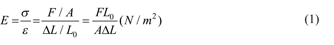
In this equation, E represents the Elastic modulus, F is the force exerted on an object under tension, A is the actual cross-sectional area, ΔL is the amount by which the length of the object changes and L0 is the original length of the object.
The Elastic modulus of the resilient material can be obtained by conducting compression test on the material and using the equation above.
Dynamic stiffness
The dynamic stiffness of the resilient material can be obtained using the measurement and analysis methods specified in ISO 9052-1. 10 This standard presents experimental methods and equations for obtaining the dynamic stiffness of resilient materials used in floating floor structures.
Figure 1 illustrates the process of measuring the dynamic stiffness of the resilient material. Samples, each measuring 200 mm in width and height, are placed on the floor, and an 8 kg load plate of the same size is placed on top of them. An accelerometer is attached to the load plate, and an impact hammer is used to apply an instantaneous impact, allowing the measurement of the system’s natural vibration frequency.
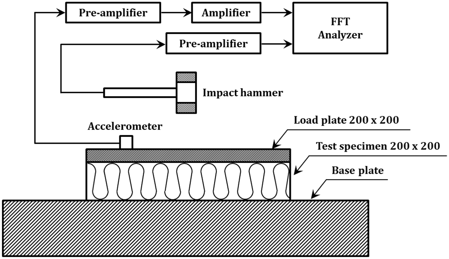
Measurement method of dynamic stiffness of resilient material (ISO 9052-1).
The dynamic stiffness can be determined by substituting the measured natural vibration frequency f0 into the following equation.

In equation (2), S’t is the apparent dynamic stiffness per unit area, f0 is the system’s natural frequency and m’t is the mass per unit area of the load plate.
Methods
Accurate reproduction of the natural frequency of the floating floor system, specifically the dynamic stiffness of the resilient layer, is essential for ensuring the precision of heavy-weight floor impact sound predictions in FEA simulations. Figure 2 illustrates the research process for replicating the experimentally measured dynamic stiffness in FEA. In the diagram, shaded regions indicate key analysis steps, where dashed lines represent experimental measurements, and solid lines denote numerical predictions using FEA.
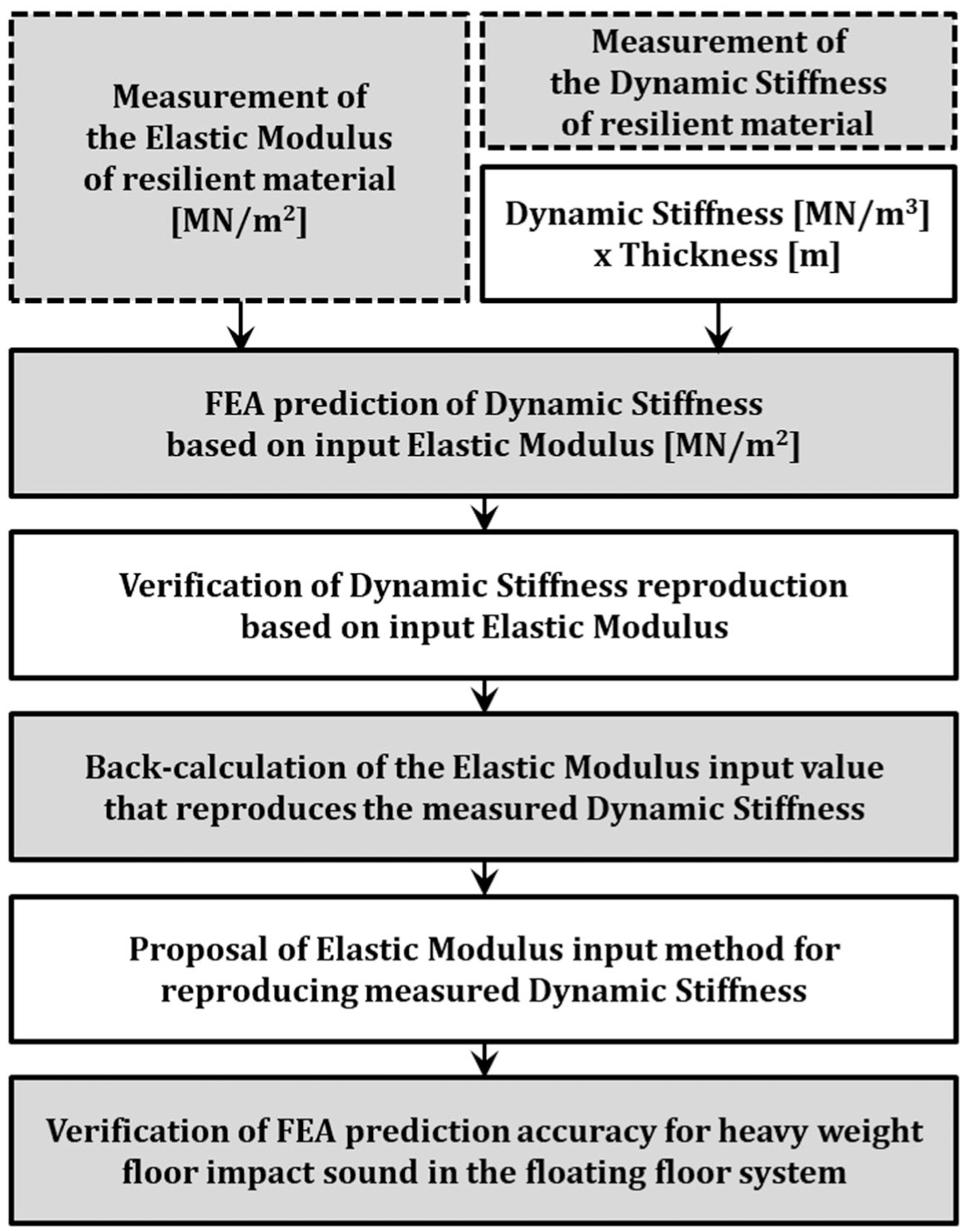
Derivation process of the input elastic modulus for accurate FEA prediction of heavy-weight floor impact sound in a floating floor system.
When modeling a floating floor system in an FEA program, the material properties of the resilient layer are defined in terms of elastic modulus rather than dynamic stiffness. To address this, the elastic modulus and dynamic stiffness of four types of resilient layers were experimentally measured.
Subsequently, the FEA software COMSOL Multi-physics was used to model the configuration required for dynamic stiffness measurement, as shown in Figure 1. In this model, the experimentally measured elastic modulus and the converted values obtained by multiplying the measured dynamic stiffness by the material thickness were assigned as input parameters for the four types of resilient layers. The validity of this approach was then verified by checking whether the measured dynamic stiffness was accurately reproduced in the simulation.
Next, the elastic modulus input value required to ensure the reproduction of the measured dynamic stiffness in the FEA program was inversely estimated. The relationship between this estimated value and the initially assigned input values was analyzed. Based on this, the appropriate method for defining the elastic modulus of the resilient layer in floating floor system modeling was identified. Finally, a floating floor system was installed in an apartment building, and the accuracy of heavy-weight floor impact sound predictions was experimentally and numerically validated.
Measurement of elastic modulus of resilient materials
The elastic modulus was measured through compression tests using a universal testing machine (UTM). The elastic modulus of each sample was calculated based on the relationship between force and deformation, as expressed in equation (1).
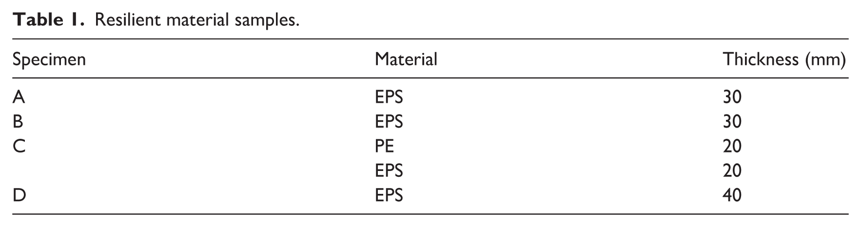
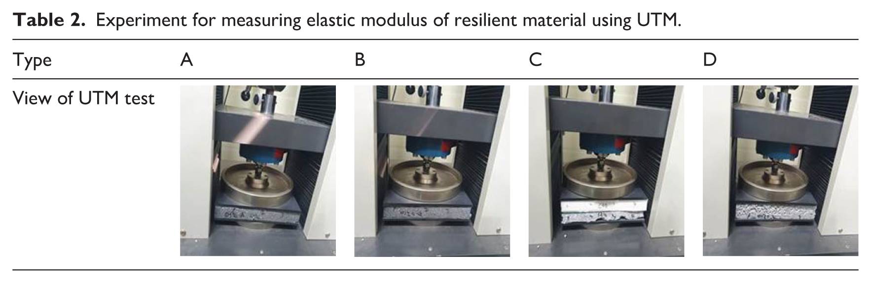
Table 1 presents the four types of resilient material samples used in the experiment, including their thickness and composition. Samples A, B, and D were composed of a single material, expanded polystyrene (EPS), while Sample C was a laminated structure consisting of polyester (PE) and EPS. Table 2 shows the compression test setup using the UTM.
Resilient material samples.
Experiment for measuring elastic modulus of resilient material using UTM.
Measurement of dynamic stiffness of resilient materials
The dynamic stiffness of the resilient layer was measured following ISO 9052-1, by determining the natural frequency (f0) and calculating the dynamic stiffness using equation (2).
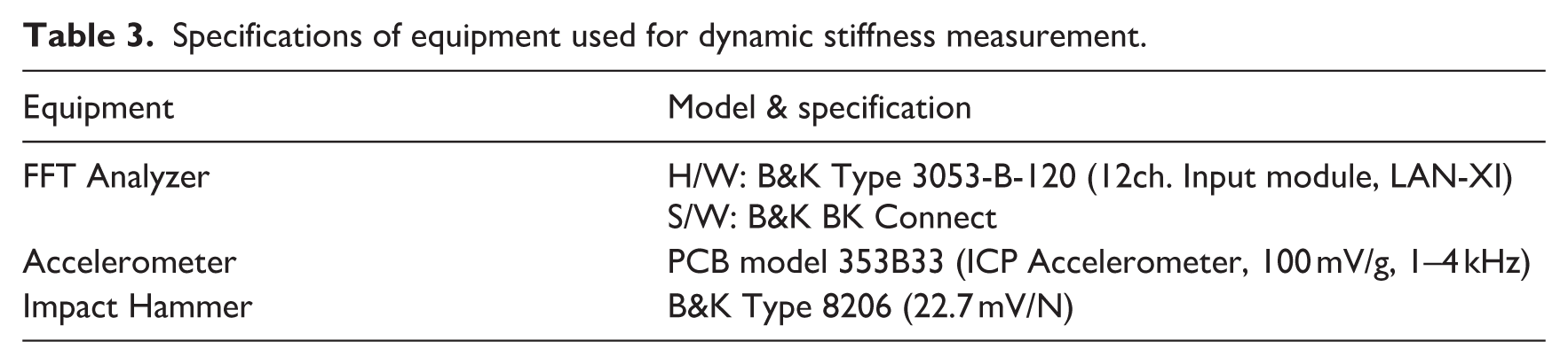
Figure 3 illustrates the experimental setup for measuring dynamic stiffness, while Table 3 presents the specifications of the accelerometer, impact hammer, and frequency analyzer used in the measurement process.
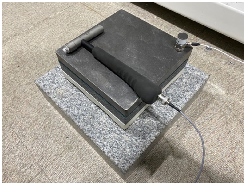
Dynamic stiffness measurement setup.
Specifications of equipment used for dynamic stiffness measurement.
Implementation of dynamic stiffness in FEA
The feasibility of reproducing the measured dynamic stiffness in FEA predictions was analytically examined using the elastic modulus measured in Section 3.1 and the dynamic stiffness measured in Section 3.2, both multiplied by the thickness of the resilient layer. To achieve this, a resilient layer sample and a loading plate model were implemented in the FEA software COMSOL Multi-physics.
Figure 4 illustrates the modeled loading plate and resilient layer in COMSOL. In the figure, the blue region represents the resilient layer, while the black region represents the loading plate.
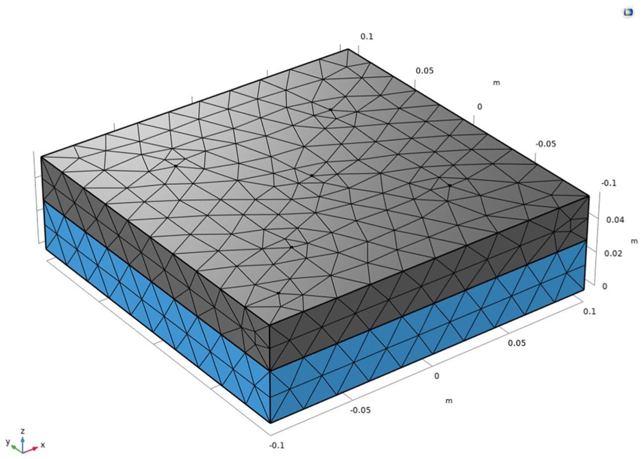
Dynamic stiffness analysis modeling (COMSOL v6.0).
The loading plate was defined as steel, with a density of 7870 kg/m3, and its thickness was set to 0.026 m to achieve a mass of 8 kg. The density of the resilient layer was set to 18 kg/m3, and its bottom surface was fixed. The elastic modulus of the resilient layer was assigned using two different methods: the elastic modulus measured from UTM tests and the converted value obtained by multiplying the measured dynamic stiffness by the thickness. The results were then compared.
In the FEA model, a 1 N force was applied in the −Z direction at the center of the top surface of the loading plate to predict the natural frequency f0. The obtained natural frequency was then substituted into equation (2) to calculate the dynamic stiffness.
Improvement of heavy-weight floor impact sound prediction accuracy in floating floor systems
After verifying the appropriate elastic modulus input method for the resilient layer through FEA-based dynamic stiffness simulations, a floating floor system was installed in an actual residential building to evaluate the improvement in prediction accuracy of heavy-weight floor impact sound. The prediction accuracy was assessed by comparing the field measurement results with two different input methods: the conventional approach, which obtains the elastic modulus by multiplying the measured dynamic stiffness by the thickness, and the method proposed in this study. The error between the predicted and measured values was analyzed to validate the effectiveness of the proposed method.
Overview of heavy-weight floor impact sound measurements in floating floor systems
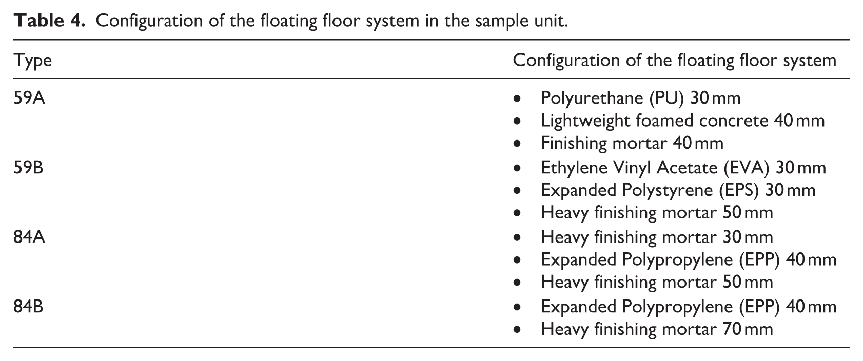
Field measurements of heavy-weight floor impact sound were conducted in a reinforced concrete apartment building located in Seoul, South Korea. The experiment was performed on four sample units, consisting of two 59 m2 unit types and two 84 m2 unit types. The apartment structure was a wall-type structural system with a 210 mm-thick slab. The cross-sectional configuration of the floating floor system is presented in Table 4, while Figure 5 illustrates the installed resilient layer.
Configuration of the floating floor system in the sample unit.
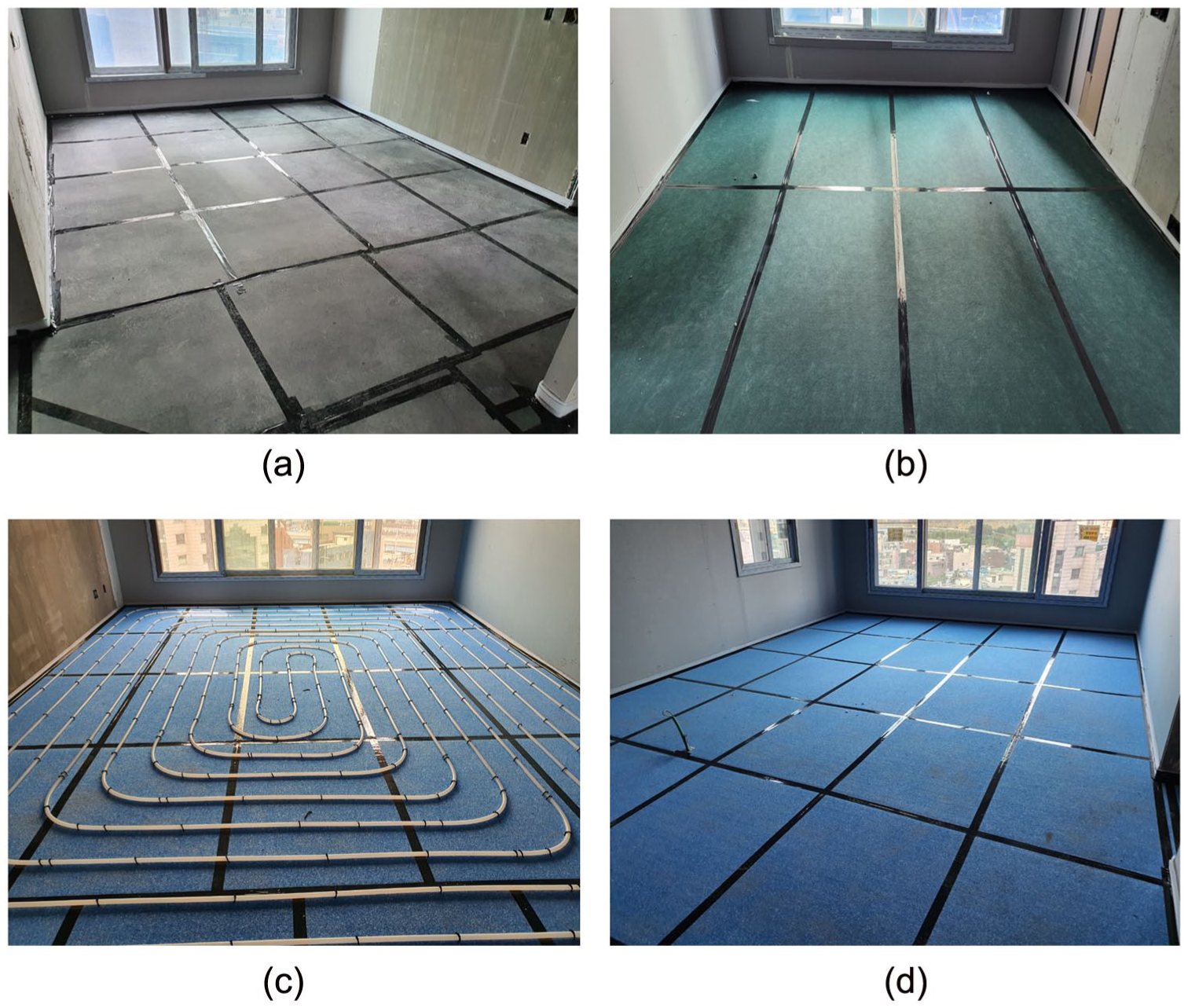
Installation of the resilient material of the floating floor system in each experimental unit. (a) 59A – PU 30 mm. (b) 59B – EVA 30 mm + EPS 30 mm. (c) 84A – EPP 40 mm. (d) 84B – EPP 40 mm.
The floating floor system was applied in the living room, kitchen, and hallway, excluding the bedrooms. At the boundary between the floating floor and the bedroom, wooden plywood was installed to prevent mortar overflow. The components of the floating floor system were arranged sequentially from the slab upward, as shown in Table 4. For instance, in the Type 59A unit, a 30 mm-thick polyurethane (PU) layer was placed on the 210 mm base slab, followed by the sequential application of 40 mm lightweight aerated concrete and 40 mm finishing mortar.
The finishing materials were designed with specific unit weights to ensure accurate representation of field conditions. The general finishing mortar had a density of 2100 kg/m3, the lightweight aerated concrete was 600 kg/m3, and the heavy finishing mortar was 2400 kg/m3.
Through the processes described in Sections 3.1 to 3.3, the appropriate elastic modulus input method for the resilient layer was determined. To apply this method to FEA predictions for actual field experiments, the dynamic stiffness of the resilient layer samples used in each apartment unit type was measured.
Additionally, to evaluate the impact sound insulation performance of the floating floor system applied in each unit, measurements and analyses were conducted following ISO 16283-2 and ISO 717-2.32,33 Since the average results obtained from five excitation points may not fully reflect localized characteristics, the analysis primarily focused on data obtained from a standard heavy-weight impact source using a rubber ball dropped at the center of the living room for detailed validation against FEA predictions.
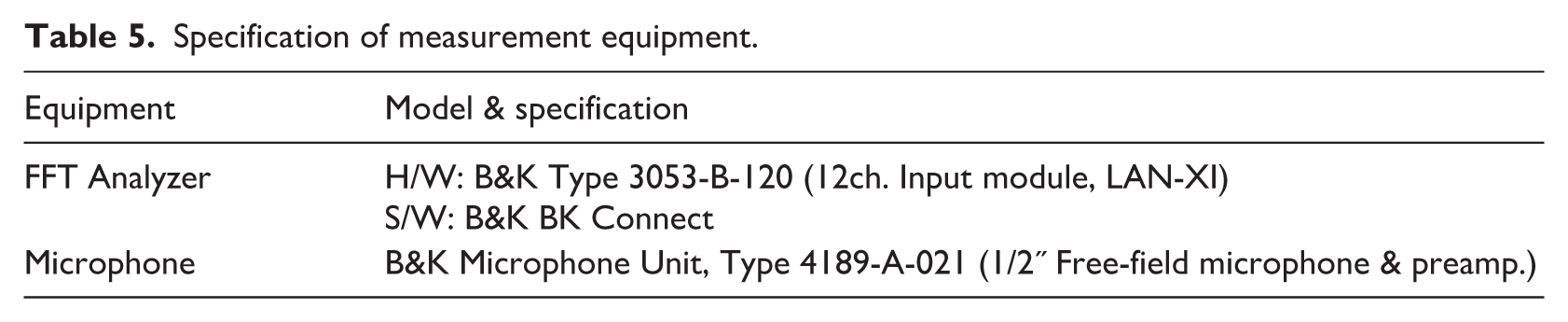
The equipment used for the measurement and analysis of heavy-weight floor impact sound insulation performance is summarized in Table 5, while Figure 6 presents the floor plan of the test units, along with the impact excitation points and microphone placement locations.
Specification of measurement equipment.
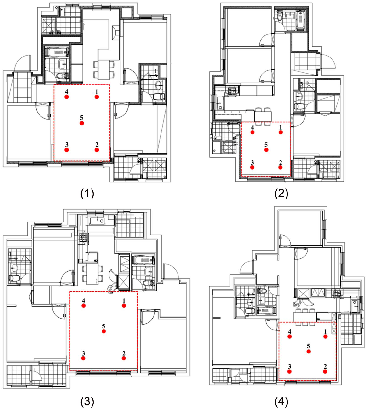
Floor plan of target unit for measurement. (1) 59A Type, (2) 59B Type, (3) 84A Type, (4) 84B Type.
Overview of heavy-weight floor impact sound analysis in floating floor systems
To predict heavy-weight floor impact sound in a box-frame concrete apartment with a floating floor system, a 3D solid element model based on continuum mechanics theory was implemented using COMSOL Multi-physics. The analysis was conducted utilizing the Acoustics-Structure Interaction module, and the governing equations used in the simulation are described below.
The structural mechanics equation is derived from the equations of motion in continuum mechanics. The equation below represents the equilibrium of forces at an arbitrary point, which can be applied in dynamic analysis, such as transient analysis or frequency domain analysis, when the structure vibrates over time. In this study, frequency domain analysis was performed.

The equation components include σ, the stress tensor; f, the external force (such as body force like gravity); ρs, the material density; u, the displacement vector; and ∇⋅σ, the divergence of the stress tensor.
The relationship between stress and strain in a structure, known as the constitutive equation, follows Hooke’s Law for linear elastic materials and is expressed as shown below.

The equation σ = C: ε represents the linear elastic constitutive relation, where C is the elasticity tensor and ε is the strain tensor, with “:” denoting the double dot product.
The relationship between strain and displacement, known as the strain-displacement relation, can be determined using the following equation.
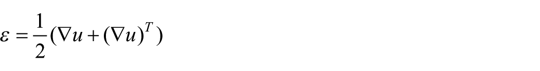
Acoustic waves are expressed as pressure variations in a fluid, and in acoustics, they are described using the wave equation. The linearized acoustic wave equation represents the propagation of acoustic waves in air or water and is given by the following equation.
In the wave equation, p represents the acoustic pressure,
At the interface between the structure and the acoustic fluid, the continuity condition is applied to ensure the equilibrium of forces and the continuity of motion. The relationship between acoustic pressure and displacement on the structural surface can be expressed by the following equation.

In the context of wave-structure interaction,
This equation represents the force equilibrium relationship between the structural stress and acoustic pressure, illustrating that when the structure vibrates, it exerts a force on the adjacent air layer, thereby generating acoustic pressure.
The continuity of velocity between the fluid and the structural displacement in the acoustic domain can be expressed by the following equation. This condition implies that at the interface between the structure and the fluid, the particle velocity of the fluid must be equal to the surface velocity of the structure.
In fluid-structure interaction, v represents the particle velocity of the fluid, while ∂u/∂t denotes the surface velocity of the structure.
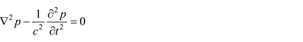
To predict heavy-weight floor impact sound in an apartment, the impact force of the standard heavy-weight impact source is required. The impact force data in the 1–800 Hz range was obtained by dropping a rubber ball from a height of 1 m, with the force input recorded using a force sensor. The validity of the measured impact force was verified by comparing the impact force exposure level with the reference values specified in Annex A of ISO 16283-2.
Figure 7 illustrates the impact force measurement setup, while Figure 8 presents the measured impact force results. The derived impact force data was applied in the FE model as a –Z directional force at the center of the living room.
Impact force measurement test of the standard heavy-weight impact source.
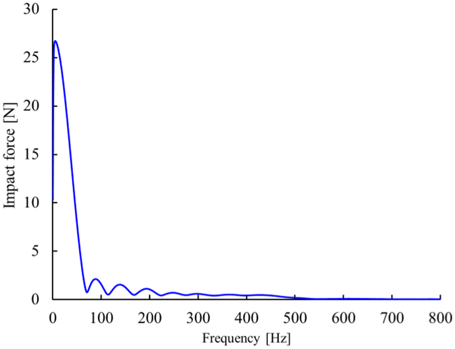
Measured impact force of the standard heavy-weight impact source (1–800 Hz, resolution = 1 Hz).
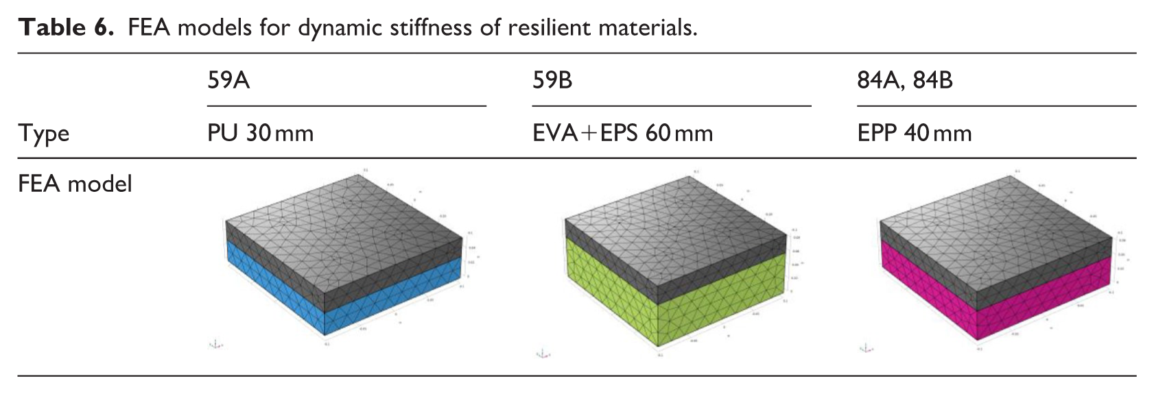
Before conducting FEA predictions for heavy-weight floor impact sound in the floating floor system, an FEA model was developed to investigate the elastic modulus input method for the resilient layers used in Table 4. The dynamic stiffness prediction model was constructed using the same approach described in Section 3.3, and the FEA models for each resilient layer are presented in Table 6.
FEA models for dynamic stiffness of resilient materials.
To predict heavy-weight floor impact sound in the floating floor system, four different floor plan types were modeled and analyzed using FEA. Table 7 presents the FEA models corresponding to each floor plan type. The model included two unit spaces, representing the upper and lower floors, with fixed boundary conditions assigned to the upper and lower boundary surfaces. The concrete structure, resilient layer, and mortar layer were modeled as
FEA model for heavy-weight floor impact sound in floating floor systems.
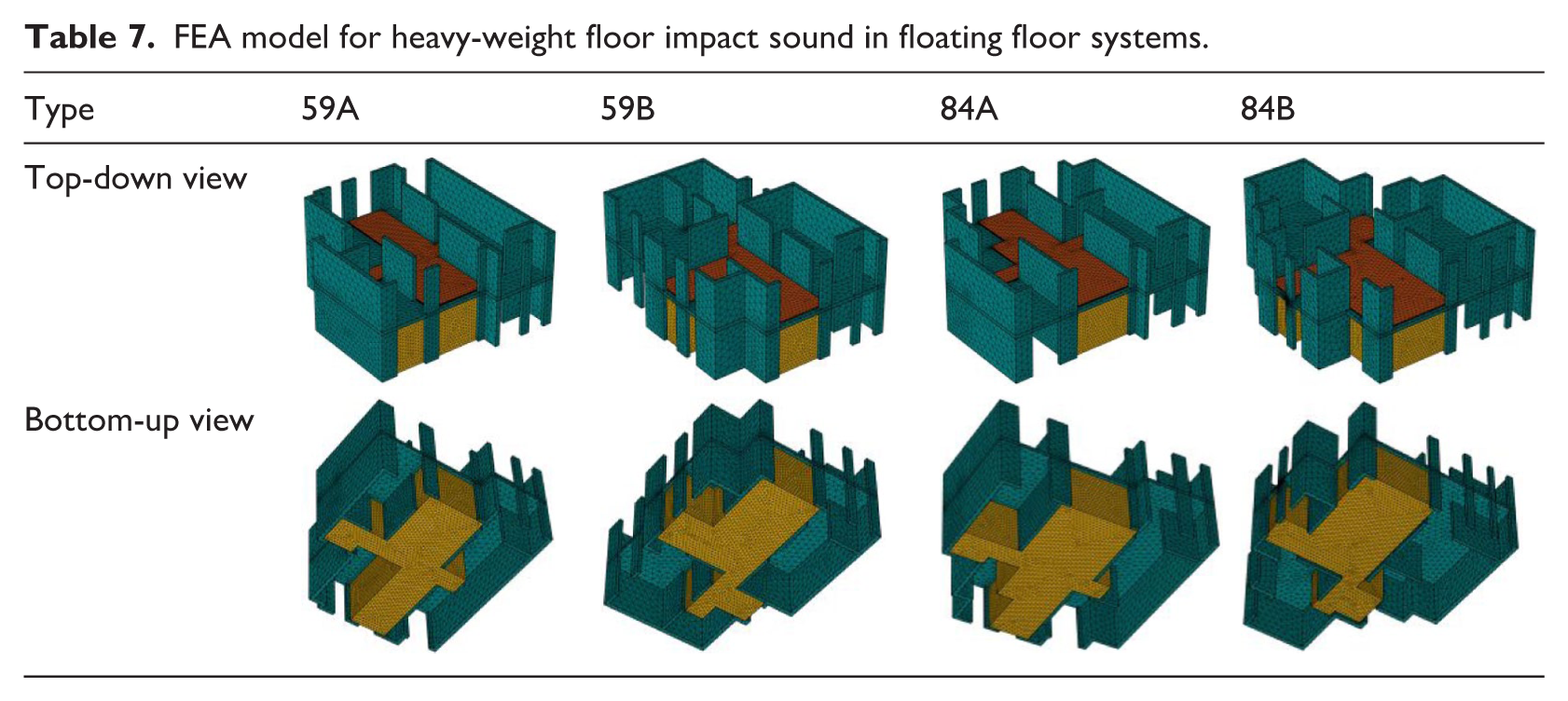
3D solid elements, while the air domain in the living room, kitchen, and hallway of the lower unit was represented using a solid air model. The material properties were defined based on standard values, where concrete had a density of 2400 kg/m3, an elastic modulus of 17.5 GPa, and a Poisson’s ratio of 0.167, while air had a density of 1.225 kg/m3 and a speed of sound of 345 m/s.
To capture the sound pressure levels in the lower unit, five receiver points were designated. Four measurement points were positioned 0.75 m away from the living room walls, while one was located at the center of the living room at a height of 1.2 m. The maximum sound pressure levels were analyzed in 1 Hz increments over a frequency range of 44–710 Hz. The obtained sound pressure levels were then converted into one-third octave bands, and an energy-averaged A-weighting correction was applied to compare the numerical predictions with the measured results.
To evaluate the prediction accuracy, two different methods were applied to define the elastic modulus of the resilient layer. The first method involved multiplying the measured dynamic stiffness by the thickness, while the second method used back-calculation based on FEA-based dynamic stiffness predictions. The resulting predictions of heavy-weight floor impact sound were compared to assess the differences between these two approaches.
Results
Measurement results of elastic modulus of resilient materials
To measure the elastic modulus of the four types of resilient layers listed in Table 1, a universal testing machine (UTM) was used to generate displacement-force graphs for each sample. The experimental setup is shown in Table 2. The elastic modulus was calculated using equation (1), where the sample area was 200 mm × 200 mm, and the thickness variation was measured as a function of applied load using the UTM.
The displacement-force graph for the resilient layer samples is presented in Figure 9. The results indicate that the samples exhibited linear deformation within the 0.0–0.5 mm range under loads up to approximately 10 N. However, beyond this load threshold, the displacement increased rapidly as additional force was applied.
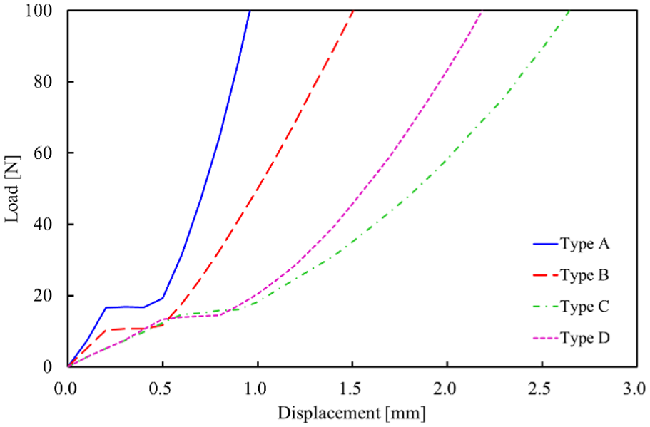
Displacement-Load graph of resilient material.
Samples A and B had a thickness of 30 mm, while Samples C and D had a thickness of 40 mm. The data showed that thicker samples exhibited a more gradual slope in the displacement-force relationship, indicating lower deformation rates under increasing loads.
Assuming the dynamic stiffness test conditions, the elastic modulus was calculated based on the displacement of each resilient layer sample under a load of approximately 80 N, which corresponds to the weight of the loading plate of 8 kg. The measured displacement values and the calculated elastic modulus for each sample are presented in Table 8.
Measurement results of elastic modulus for resilient material.
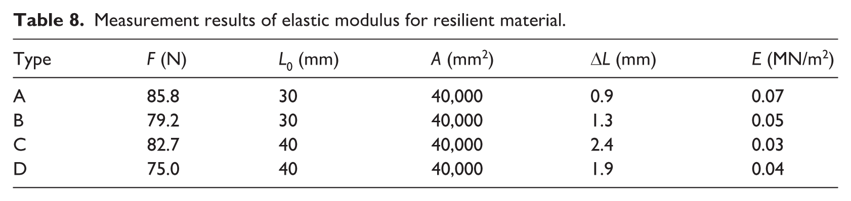
The results from the universal testing machine experiments showed that the elastic modulus of the four resilient layer samples ranged from 0.03 to 0.07 MN/m2. The measured values will be used as input parameters in the dynamic stiffness finite element analysis model described in Table 6, and in Section 4.3, the accuracy of the finite element analysis-reproduced dynamic stiffness will be evaluated.
Measurement results of dynamic stiffness of resilient materials
The dynamic stiffness measurements for the four types of resilient materials, along with their natural frequencies, are presented in Table 9. According to ISO 9052-1, an 8 kg loading plate was placed on each resilient material sample, and the natural frequency of the elastic support system was measured. The measured values were then substituted into equation (2) to calculate the dynamic stiffness.
Measurement results of dynamic stiffness for resilient material.
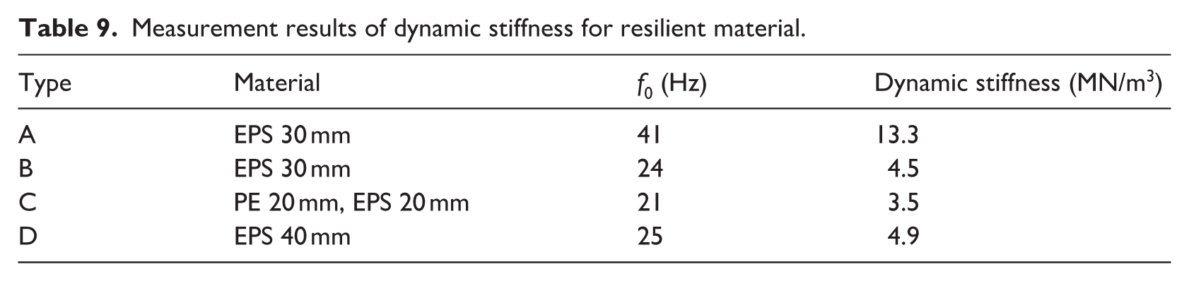
Although resilient materials A and B were both 30 mm thick EPS materials, their dynamic stiffness values were measured as 13.3 and 4.5 MN/m3, respectively. This variation is likely due to the nature of EPS, which is produced by expanding small polystyrene beads. The degree of expansion and the structural integrity of the expanded beads can significantly influence the dynamic stiffness of the material. 14
Resilient material C was a composite resilient material consisting of 20 mm polyester and 20 mm EPS, with a measured dynamic stiffness of 3.5 MN/m3. Resilient material D, which was composed of 40 mm EPS, exhibited a dynamic stiffness of 4.9 MN/m3, further confirming that the expansion characteristics of the beads influence the dynamic stiffness of EPS materials.
The measured dynamic stiffness values of the four resilient materials were used as the reference data for FEA predictions, and they were applied to verify the appropriate input method for the elastic modulus of resilient materials in the simulation.
FEA prediction results of dynamic stiffness of resilient materials
The actual elastic modulus of the resilient materials measured using the universal testing machine was input into the dynamic stiffness analysis model to verify whether the predicted natural frequency and dynamic stiffness corresponded well with the measured values. Figure 10 presents the measured and predicted natural frequencies and dynamic stiffness values for each resilient material.
Comparison of predicted dynamic stiffness derived from elastic modulus input and measured dynamic stiffness.
The FEA-predicted dynamic stiffness obtained by inputting the measured elastic modulus showed discrepancies compared to the experimentally measured dynamic stiffness. The predicted values were lower than the measured values by a range of 1.7–9.1 MN/m3. These results indicate that, to accurately predict the dynamic stiffness and natural frequency of resilient materials in the FEA model, it is necessary to determine the elastic modulus input value that ensures the measured dynamic stiffness is reproduced rather than directly using the measured elastic modulus.
To determine the appropriate elastic modulus input value, previous studies were referenced, and the measured dynamic stiffness of the resilient material was multiplied by its thickness to obtain the input value, which was defined as Er. The FEA-predicted dynamic stiffness was then compared with the measured dynamic stiffness when Er was used as the elastic modulus input. 24
Subsequently, the elastic modulus input value that ensured the predicted dynamic stiffness matched the measured dynamic stiffness was identified and defined as Ee. The relationship between Ee and Er was then analyzed. If this relationship remains consistent, it could contribute to improving the dynamic stiffness analysis of various resilient materials and enhancing the prediction accuracy of heavy-weight floor impact sound in floating floor systems.
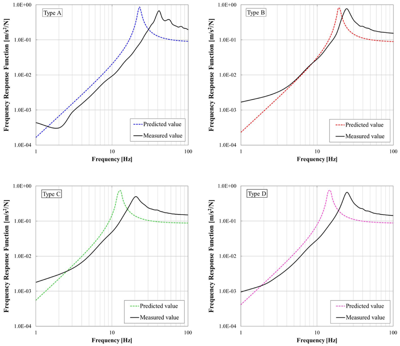
Figure 11 presents the FEA prediction results obtained by inputting Er and Ee into the dynamic stiffness analysis model of the resilient materials, along with the corresponding measured values.
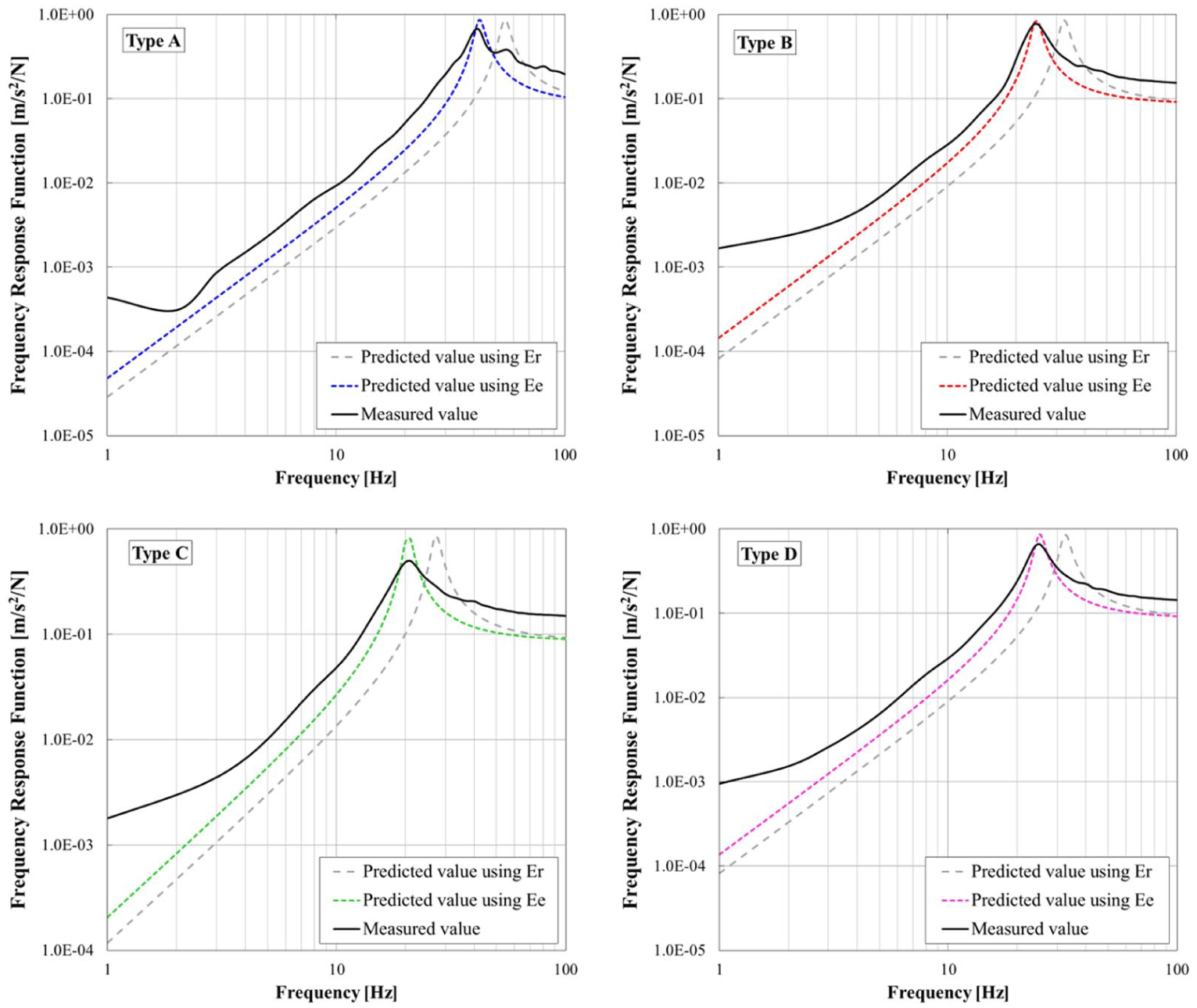
FEA prediction results of dynamic stiffness based on elastic modulus input methods for resilient materials.
When Er, which was obtained by multiplying the measured dynamic stiffness by the material thickness, was used as the elastic modulus input, the predicted dynamic stiffness ranged from 5.8 to 23.9 MN/m3. These values were approximately 1.6 to 1.8 times higher than the measured results. To ensure that the FEA-predicted dynamic stiffness matched the measured values, Er was adjusted to determine Ee. The analysis showed that for all four resilient material samples, Ee was 60% of Er.
These findings indicate that for FEA-based dynamic stiffness predictions of resilient materials with thicknesses ranging from 30 to 40 mm, the appropriate method for defining the elastic modulus input is to multiply the measured dynamic stiffness by the material thickness and then apply a correction factor of 0.6.
However, since the resilient material samples in this experiment were limited to EPS materials with thicknesses between 30 and 40 mm, further validation was conducted in Section 4.4 using resilient materials of different compositions and greater thicknesses. Additionally, a floating floor system was installed as a mock-up in an actual apartment building, and heavy-weight floor impact sound measurements were performed to further verify the prediction accuracy.
Improvement of prediction accuracy for heavy-weight floor impact sound in floating floor systems
The dynamic stiffness of the resilient materials used in the floating floor systems of each test unit was measured, and the corresponding elastic modulus was applied in the FEA model using two different input methods.
The first method involved defining Er, where the measured elastic modulus was obtained by multiplying the measured dynamic stiffness by the material thickness. The second method involved defining Ee, which was adjusted to ensure that the FEA-predicted dynamic stiffness matched the measured dynamic stiffness. The analysis confirmed that for resilient materials with thicknesses of 30–40 mm, Ee was 0.6Er, while for materials with a thickness of 60 mm, Ee was 0.66 Er.
The dynamic stiffness analysis model was constructed as described in Table 6, and the results showed that when Er was used as the elastic modulus input, the FEA-predicted dynamic stiffness tended to be approximately 1.2 times higher than the measured dynamic stiffness.
To verify the prediction accuracy of heavy-weight floor impact sound based on the elastic modulus input method for resilient materials, the FEA prediction results for the floating floor system were compared across the apartment floor plans presented in Tables 4 and 7.
Figure 12 illustrates the measured heavy-weight floor impact sound for each unit, along with the FEA-predicted results based on different elastic modulus input methods. To quantitatively analyze the degree of agreement and error rate between the predicted and measured results, a first-order Pearson correlation analysis was conducted, and the correlation coefficient (R-value) was derived and compared.
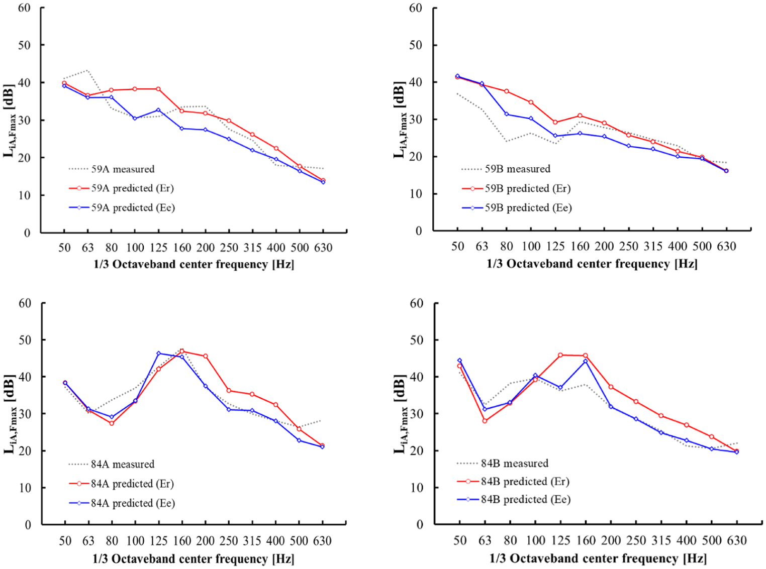
FEA prediction results of heavy-weight floor impact sound based on elastic modulus input methods for resilient materials.
The error rate was evaluated using the root mean squared error (RMSE) method, which is expressed by the equation below. A lower RMSE value, approaching zero, indicates a smaller discrepancy between the predicted and measured values.
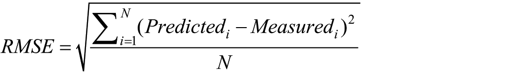
In this equation, N represents the number of data points, Predictedᵢ denotes the predicted data, and Measuredᵢ refers to the measured data.
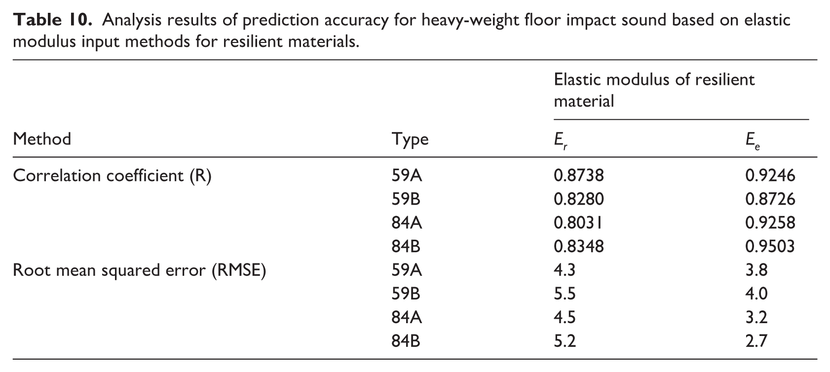
The analysis of heavy-weight floor impact sound predictions based on different elastic modulus input methods for resilient materials showed that the correlation coefficient R increased across all floor plan types, indicating an improved alignment with the measured frequency-dependent trend. The root mean squared error (RMSE), which quantifies the error rate across different frequency bands, demonstrated an improvement when using Ee instead of Er, with reductions of 11.6% for Type 59A, 27.3% for Type 59B, 28.9% for Type 84A, and 48.1% for Type 84B (Table 10).
Analysis results of prediction accuracy for heavy-weight floor impact sound based on elastic modulus input methods for resilient materials.
The primary objective of heavy-weight floor impact sound prediction in floating floor systems is not to precisely match the impact sound performance of specific units but rather to prevent low-frequency amplification effects in particular floor plans, even when variations due to on-site construction tolerances are considered. Given this perspective, improving prediction accuracy is essential for practical application.
In particular, Figure 10 shows that the predicted impact sound levels using Er were higher than those using Ee. This discrepancy can be attributed to the dynamic stiffness analysis model, where the predicted dynamic stiffness values using Er were approximately 1.2 times higher than the measured values. As a result, the floating floor system exhibited resonance effects at relatively higher frequencies than in actual conditions, due to the increased stiffness of the concrete structure in the simulation.
Discussion
This study experimentally investigated a method for incorporating the dynamic stiffness of resilient materials to improve the FEA prediction accuracy of floating floor systems, which are applied to mitigate floor impact sound in apartments. The FEA model was constructed using 3D solid elements based on continuum mechanics, which, unlike shell elements that neglect shear deformation and internal damping, fully account for thickness variations and deformation in all directions.
In previous studies on heavy-weight floor impact sound predictions, Cho20,23 and Park et al. 22 modeled the floating floor system using shell elements and defined the spring constant (MN/m) by multiplying the measured dynamic stiffness (MN/m3) by the sample area (m2). In contrast, Kim et al. 24 used 3D solid elements and input the elastic modulus by multiplying the measured dynamic stiffness by the thickness of the resilient material in the FEA program. Since most commercial finite element analysis (FEA) software uses elastic modulus to define the material properties of resilient layers rather than dynamic stiffness or dynamic modulus, it is necessary to determine an appropriate method to represent measured dynamic stiffness within such modeling frameworks.
To verify whether directly multiplying these two parameters provides a valid method for reproducing the natural frequency of the floating floor system in 3D solid FEA modeling, several experiments were conducted. The elastic modulus of four resilient material samples was measured using a universal testing machine, and these values were input into the FEA model to predict dynamic stiffness. The results showed that the FEA-predicted dynamic stiffness was approximately 31%–62% of the experimentally measured values.
These findings indicate that simply multiplying the measured dynamic stiffness by the thickness is not an appropriate method for accurately representing the natural frequency of the floating floor system. Therefore, further investigation was conducted to establish a more accurate implementation method.
When the measured dynamic stiffness of the resilient material was multiplied by its thickness and input as the elastic modulus in the FEA model, as done in previous studies, 24 the FEA-predicted dynamic stiffness was 175.2% of the measured value. To correct this discrepancy and align the predicted values with the measured dynamic stiffness, the input elastic modulus was adjusted to 60%–66% of the product of the measured dynamic stiffness and thickness. The FEA prediction results based on this adjusted input method showed an error within 0.6 MN/m3 compared to the measured dynamic stiffness.
Applying this input method to the heavy-weight floor impact sound prediction of the floating floor system in a box-frame concrete apartment resulted in an improvement in prediction accuracy of 11.6%–48.1%, based on the RMSE criterion, compared to the conventional input method.
However, since this study used COMSOL Multi-physics for FEA simulations, different finite element analysis software may yield variations in prediction results. Therefore, rather than applying the exact input method proposed in this study, it is recommended to first implement a dynamic stiffness modeling approach tailored to the specific FEA software being used. This process would ensure that the measured dynamic stiffness is accurately represented when predicting floor impact sound in floating floor systems in apartment buildings.
Additionally, the resilient material samples analyzed in this study were limited to eight types, indicating the need for further validation with a wider range of resilient materials.
Furthermore, to improve the prediction accuracy of heavy-weight floor impact sound, it is also essential to assess the vibration characteristics of the structural framework in box-frame apartments. Since the floating floor system interacts with the natural frequency of the slab, potentially inducing resonance in the low-frequency range, achieving high-accuracy predictions requires enhancing the accuracy of vibration characteristics in the bare structural state. To ensure the stability of the analysis results, additional field measurements and numerical simulations should be conducted on both the floating floor system and the structural framework in actual construction sites.
Conclusion
This study experimentally and numerically investigated the implementation of dynamic stiffness for resilient materials to improve the FEA prediction accuracy of heavy-weight floor impact sound in box-frame concrete apartments.
The elastic modulus of four types of resilient materials was measured using a universal testing machine, and the measured values were input into the dynamic stiffness FEA prediction model. The results showed that the FEA-predicted dynamic stiffness was 31%–62% of the experimentally measured dynamic stiffness.
When the product of the measured dynamic stiffness and thickness was used as the elastic modulus input in the FEA model, the predicted dynamic stiffness was 175.2% of the measured value. To ensure accurate predictions at 100%, the input value was adjusted to 60%–66% of the conventional input method.
By applying 60%–66% of the product of the measured dynamic stiffness and thickness as the elastic modulus input, the heavy-weight floor impact sound of the box-frame concrete apartment was predicted using FEA. Compared to the conventional elastic modulus input method, the prediction accuracy, evaluated using the RMSE criterion, improved by up to 48.1%.
Footnotes
Funding
The authors received no financial support for the research, authorship, and/or publication of this article.
Declaration of conflicting interests
The authors declared no potential conflicts of interest with respect to the research, authorship, and/or publication of this article.