
Abstract
Light metals such as Ti and Al, and carbon fiber-reinforced plastics (CFRP) are important materials employed in the aerospace and automobile industries. In this study, a thermally conductive linear friction welding (LFW) process was developed for joining these dissimilar materials, particularly Al and CFRP. By adjusting the applied pressure of LFW, the temperature at the bonding interface can be set above the melting point and below the pyrolysis point of CFRP. This made it possible to successfully accelerate the bonding reaction while preventing the formation of defects. The obtained results form the basis for the development of LFW processes used for joining dissimilar materials.
Keywords
Introduction
Carbon fiber-reinforced plastics (CFRP) are materials with excellent specific strength, rigidity, and corrosion resistance; hence, they are widely applied in aircraft, automobile bodies, and wind power generation blades.1–3 Particularly in aircraft and automobile bodies, weight reduction and fuel consumption reduction are achieved by optimizing the use of metal and CFRP. Therefore, the demand for multi-materials composed of metals and CFRP is increasing, and research investigating the joining of dissimilar materials is being actively conducted.4,5 However, joining CFRP and metals is difficult because they have different physical and electrochemical properties. Additionally, metal/CFRP dissimilar joints are limited by various issues such as low strength of the joint interface and galvanic corrosion.
At present, mechanical fastening and adhesive bonding are primarily used to join CFRP and metals.6–8 However, the mechanical fastening method poses certain challenges, such as increased costs and weight owing to the use of bolts and rivets, and decreased strength caused by stress concentration. The adhesive method exhibits problems of low productivity owing to long curing time and surface treatment before joining in addition to low environmental resistance issues, such as creep at high temperatures and strength degradation caused by moisture absorption.9–12
To circumvent the aforementioned issues present in conventional joining methods, new joining methods such as laser welding, ultrasonic welding, and friction stir welding (FSW) have been extensively investigated for joining metals and CFRP. The advantages of laser welding include non-contact processing, high efficiency, adequate accessibility, and high flexibility; several experimental analyses have been reported on joining metals and CFRP using laser welding.13–16 However, laser welding generates numerous fine pores in the CFRP melt zone, reducing the joint strength and causing the joint to rupture in the porous region. These pores commonly occur at temperatures exceeding 350 °C and are attributed to the thermal decomposition of the CFRP resin matrix. 13 Experiments on joining CFRP to metal via ultrasonic welding have also been reported.17–19 Ultrasonic welding can produce a sound joint because the interface temperature is relatively easy to control; however, the problem of dimensional limiting for the welding components restricts its application. FSW is also being actively considered for joining metals and CFRP.20–23 Nakata successfully joined an A5000 series aluminum alloy and CFRP using the thermocompression method with FSW as the heat source to obtain a sound joint and achieve base metal fracture. 6 Choi et al. fabricated a high-strength joint of pure Ti and CFRP using a silane coupling reaction to strengthen the interface bond during FSW by controlling the joining temperature. 22 Therefore, controlling the temperature of the welding interface using FSW to obtain a sound metal/CFRP overlay joint is feasible. Thus, FSW is a promising joining method; however, it has certain limitations such as a long welding time that depends on the material size; moreover, it is not suitable for butt joining.
In this study, linear friction welding (LFW), a type of solid-phase welding similar to FSW, was investigated. This joining method enables rapid joining (in as short as 1 s) irrespective of the material dimensions. 24 Additionally, both butt and overlap-type joints can be created using the heat conduction process, providing a high degree of freedom in joint shapes. In LFW, the temperature of the joining interface can be controlled by adjusting the applied pressure,25,26 rendering it suitable for joining CFRP and metals, where temperature control is important. To the best of the authors’ knowledge, no study has reported the joining of dissimilar joints between CFRP and metals using LFW. Therefore, in this study, an attempt was made to develop a novel thermally conductive process for joining Al alloy (A6061-T6) and CFRP using LFW. The LFW parameters of frequency and applied pressure were optimized, and a silane coupling reaction was used to strengthen the bond at the joining interface, resulting in sound dissimilar-material joints with high joint strength.
Experimental methods
Thermally conductive LFW
In this study, a thermally conductive LFW method for joining CFRP to metal was devised. Figure 1 illustrates a schematic of the newly proposed LFW method along with the specimen length. In thermally conductive LFW, a metal identical to the type of metal to be welded is inserted between the CFRP and metal, and friction is generated between the two metals. Frictional heat is transferred to the CFRP/metal interface, melting the CFRP and joining it with the metal via a silane coupling reaction. The silane coupling reaction is a process that forms a covalent bond between a resin and metal; it is known for its ability to enhance the bonding strength.
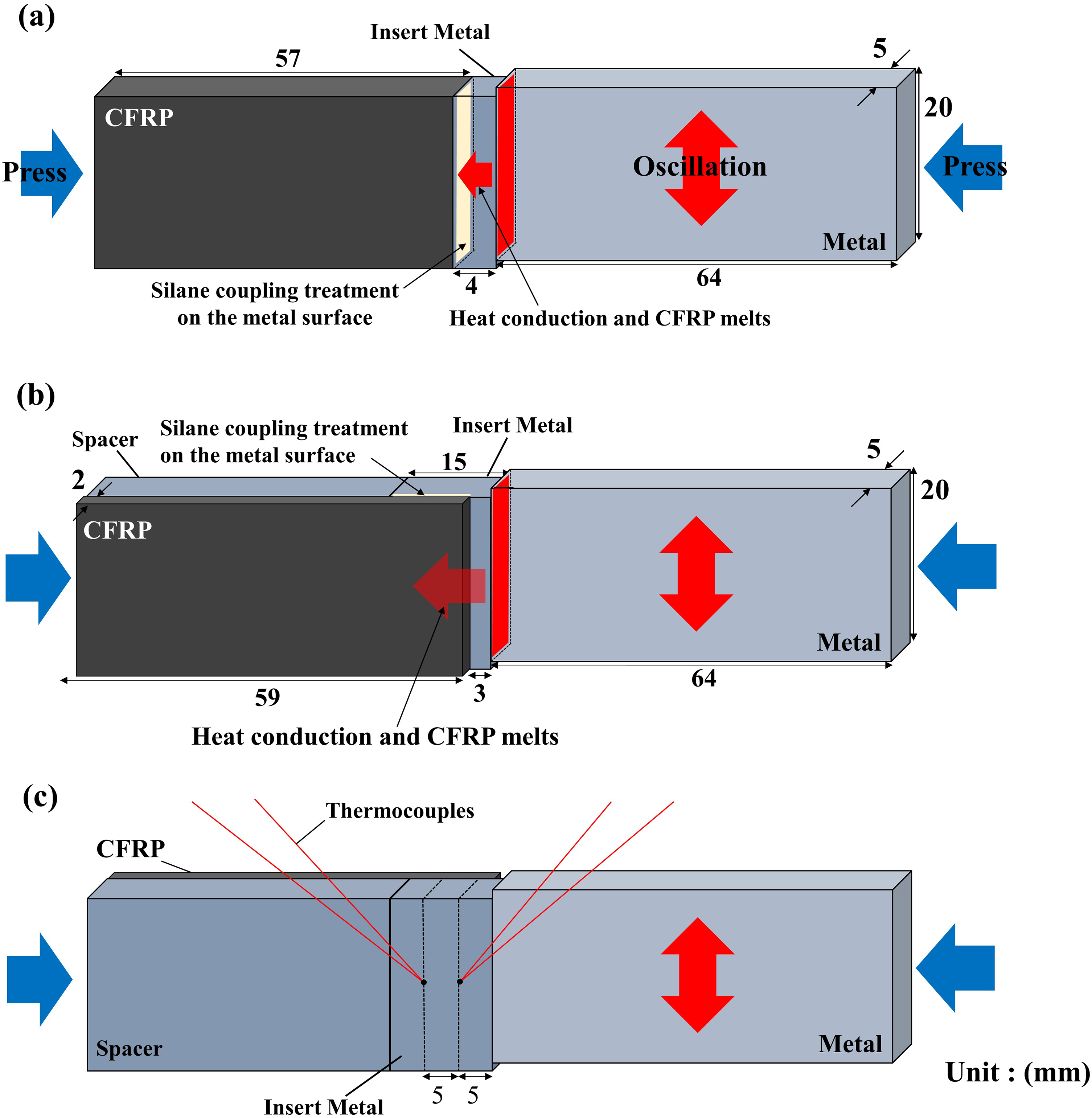
Schematic of thermally conductive LFW and the specimen length (a) butt- and (b) over lap-type welding methods. (c) Temperature measurement with thermocouples.
Typically, LFW is performed by generating friction between the materials to be joined via plastic deformation; however, direct friction between the metal and CFRP cannot generate a sufficient frictional heal and may complicate the joining process because the epoxy groups, formed on the metal surface by the silane coupling treatment, may disappear. Friction takes place between metals in the proposed thermally conductive LFW, which can increase the frictional heat and eliminate such problems. In butt-type welding, the metal and CFRP are butt-jointed, whereas in overlap-type welding, they are overlapped and joined via thermal conduction. The joined area in the butt-type welding is the cross-sectional area of the CFRP. However, in overlap-type welding, the area of CFRP melted by thermal conduction corresponds to the joined area; therefore, the overlap-type welding is expected to increase the joined area.
Materials
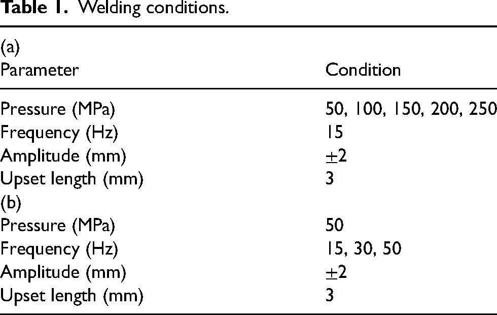
In this study, the thermoplastic resin polyamide CFRP (TLP1040-20 wt% carbon fiber polyamide 6) was used as the resin material. The carbon fiber was injection molded with alignment along the longitudinal direction of the specimen, resulting in anisotropic tensile strength, at 134 MPa in the longitudinal direction and 114 MPa in the transverse direction. The melting point and thermal decomposition point of this material were 225 and 350 °C, respectively. Additionally, A6061-T6 (Al-0.59, Si-0.4, Fe-0.27, Cu-0.02, Mn-0.96, Mg-0.12, Cr-0.01, Zn-0.04, Ti in wt%) was used as the metallic material. Its tensile strength was 310 MPa. The OFS-6040 (XIAMETE) with the 3-glycidoxypropyltrimethoxysilane epoxy functional group, which comprises epoxy groups that can react with amide groups on the metal surface, was used as a silane coupling agent. After the hydrolysis of the silane coupling agent, it bonds with the hydroxyl groups on the metal surface, forming reactive groups on the surface. These reactive groups undergo the silane coupling reaction with the amide groups of the resin material, forming a covalent bond. For the silane coupling reaction to occur, the CFRP must be in a molten state, and it is crucial to set the temperature of the bonding interface to exceed the CFRP melting point (225 °C).
As indicated in Figure 1(a), the specimen dimensions of CFRP were 5-mm-thick × 20-mm-wide × 57-mm-long in the butt-type thermally conductive LFW; the dimensions of the metal were 5-mm-thick × 20-mm-wide × 4-mm-long for the insert material and 5-mm-thick × 20-mm-wide × 64-mm-long (5 mm protrusion length) for the material subjected to friction. In the overlap-type thermally conductive LFW (Figure 1(b)), the dimensions of CFRP were 2-mm-thick × 20-mm-wide × 59-mm-long, those of the insert material were 5-mm-thick × 20-mm-wide × 15-mm-long (3 mm protrusion length), and those of the material subjected to friction were 5-mm-thick × 20-mm-wide × 64-mm-long (5 mm protrusion length).
Before the joining experiments, silane coupling treatments were applied to the joining interface of the Al alloy in the following order.
A 5.0 wt% silane coupling solution was prepared using distilled water and a silane coupling agent (OFS-6040; XIAMETER). The metal surface was polished using an 800-grit abrasive paper. The metal was soaked in the prepared solution for 30 s and dried at 20 °C for 1 h. The metal was dried further in a drying oven at 120 °C for 15 min. The CFRP surfaces were dry-polished using an 800-grit abrasive paper, degreased with ethanol, and dried for 1 h before welding.
Welding conditions
Table 1 shows the welding conditions for each welding experiment. In the joining experiments performed using butt-type thermal conduction LFW, the welding conditions were an applied pressure 50 MPa, amplitude 2 mm, and upset length 3 mm, as shown in Table 1(a). Additionally, the frequency was varied among 15, 30, and 50 Hz to investigate the effects on the mechanical properties of the joints. In the joining experiments executed using overlap-type thermal conduction LFW, the conditions shown in Table 1(a) were initially used. Subsequently, as indicated in Table 1(b), experiments were conducted by varying the applied pressure between 50, 100, 150, 200, and 250 MPa. A overlap-type LFW was designed such that a pressure of 50 MPa was applied to the overlapped area between the CFRP and metal. The welding experiment was controlled by the distance the specimen moves on the pressurized side (upset length). Because the upset length is set to 3 mm, the welding is completed when the sample moves 3 mm. During the overlap joining experiment, temperatures at 5 and 10 mm from the Al/Al interface were measured using thermocouples, as illustrated in Figure 1(c). After the welding experiments, the mechanical properties of the resulting joints were investigated via tensile testing and scanning electron microscopy (SEM) observations of the joint interface. The tensile tests were performed using SHIMADZU Autograph AG-10 TB with the tension axis parallel to the direction of pressure on the friction surface at a crosshead speed of 1 mm/min. Overlap-type joints were pulled at both ends until the joints failed in shear, and the tensile strength was reported as the value obtained by dividing the tensile strength by the shear area. Furthermore, the cross-section of the joint was polished with abrasive paper of up to 4000 grit to enable interface observation. This was followed by a final mirror polishing with a 1 µm diamond suspension, and the surface was observed using a scanning electron microscope (JEOL JSM-7001 FA SEM).
Welding conditions.
Results and discussion
Butt-type thermally conductive LFW
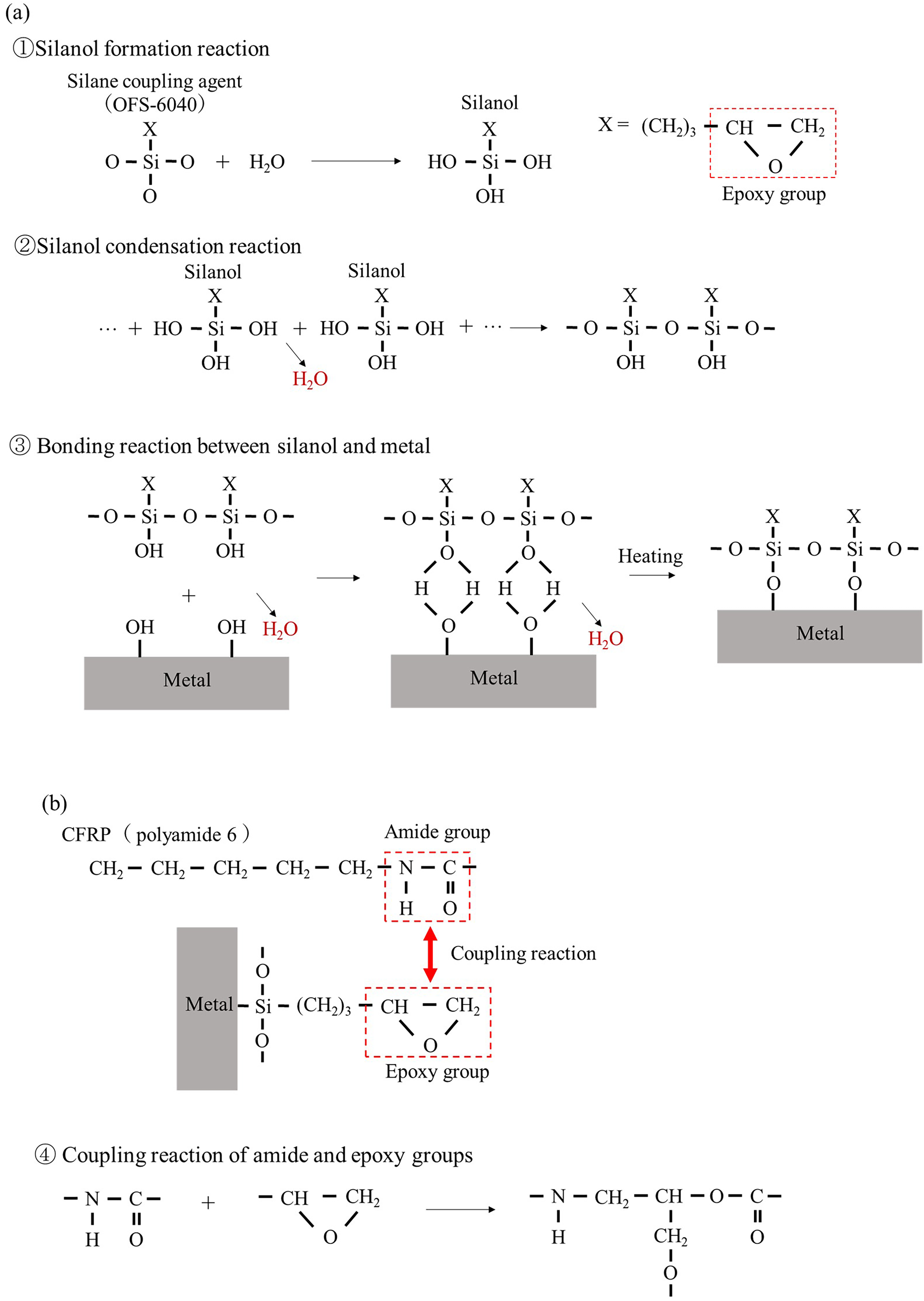
Figure 2(a) depicts the appearance of CFRP/A6061-T6 butt joints joined at frequencies of 15, 30, and 50 Hz. At all frequencies, burrs were observed between the A6061-T6 materials, and the A6061-T6/A6061-T6 and CFRP/A6061-T6 joints were successfully achieved. Molten CFRP was expelled at 15 and 30 Hz, covering the sides of the inserted A6061-T6. In this experiment, the covalent bonds formed by the silane coupling reaction are attributed to the bonding process. The formation process is considered as follows. First, as shown in Figure 3(a), a hydrolysis reaction occurs between silane coupling agent (OFS-6040) and distilled water to form silanol (Si-OH) (①). X in this figure indicates the epoxy group. The condensation reaction of silanols then forms -Si-O-Si- bonds and several hydroxyl groups (②), which are physically adsorbed to the hydroxyl groups on the metal surface through hydrogen bonding (③). Furthermore, hydrogen bonds between silanol and the hydroxyl groups on the metal surface are converted to -Si-O-metal bonds by covalent bonding due to dehydration by heating. 27 Through these processes, metal surfaces with organic epoxy groups were obtained. Subsequently, the thermal conduction in this bonding process is thought to have melted the CFRP at the interface, causing the epoxy groups on the metal surface to react with the amide groups in the CFRP to form covalent bonds (④).28–31
Silane coupling reaction. (a) Coupling mechanism between the silane coupling agent and metal surface. (b) Coupling mechanism between the amide and epoxy groups on the metal surface generated by the CFRP.
Experimental results in butt-type thermally conductive LFW. (a) Appearance of the CFRP/Al alloy joints obtained at each frequency. (b) Tensile-shear load and joined area of the joints obtained at each frequency. (c) Correlation between the joined area and tensile load.
Figure 2(b) shows the tensile load and joined area of the joints obtained at each frequency. The joined area is measured as the area of CFRP melt at the CFRP/A6061-T6 interface. The tensile loads of the CFRP/A6061-T6 joints obtained at frequencies of 15, 30, and 50 Hz were 1.1, 1.0, and 0.6 kN, respectively, and the joined areas were 45, 43, and 27 mm2, respectively. As the joined area represented the area of CFRP melt at the CFRP/A6061-T6 interface and corresponded to the area where the silane coupling reaction occurred, the tensile load increased with the increase in the joined area. Additionally, the tensile load decreased with increasing frequency. This is because the heating and cooling rates increase with the increasing frequency in LFW, 32 reducing the high-temperature holding time and resulting in insufficient adhesion and bonding reaction between the resin and metal, which lowers the joint strength.
Figure 2(c) illustrates the relationship between the tensile load and joined area for the joints obtained under each condition. The correlation between the joined area and tensile load indicates that the strength of the joined interface remains constant at approximately 24 MPa. The proportional relationship between the joined area and tensile load suggests that the tensile load can be further increased by increasing the frictional heat transfer and extending the CFRP melt area. However, increasing the tensile load in butt-type LFW is difficult because the melt area cannot be increased beyond the interfacial area of the butt joint. Therefore, to increase the joined area, a thermally conductive LFW with a layered-joining structure was devised rather than a butt-joining structure and CFRP and A6061-T6 were joined using overlap-type thermally conductive LFW.
Overlap-type thermally conductive LFW
Effect of frequency on joint tensile–shear load and microstructures
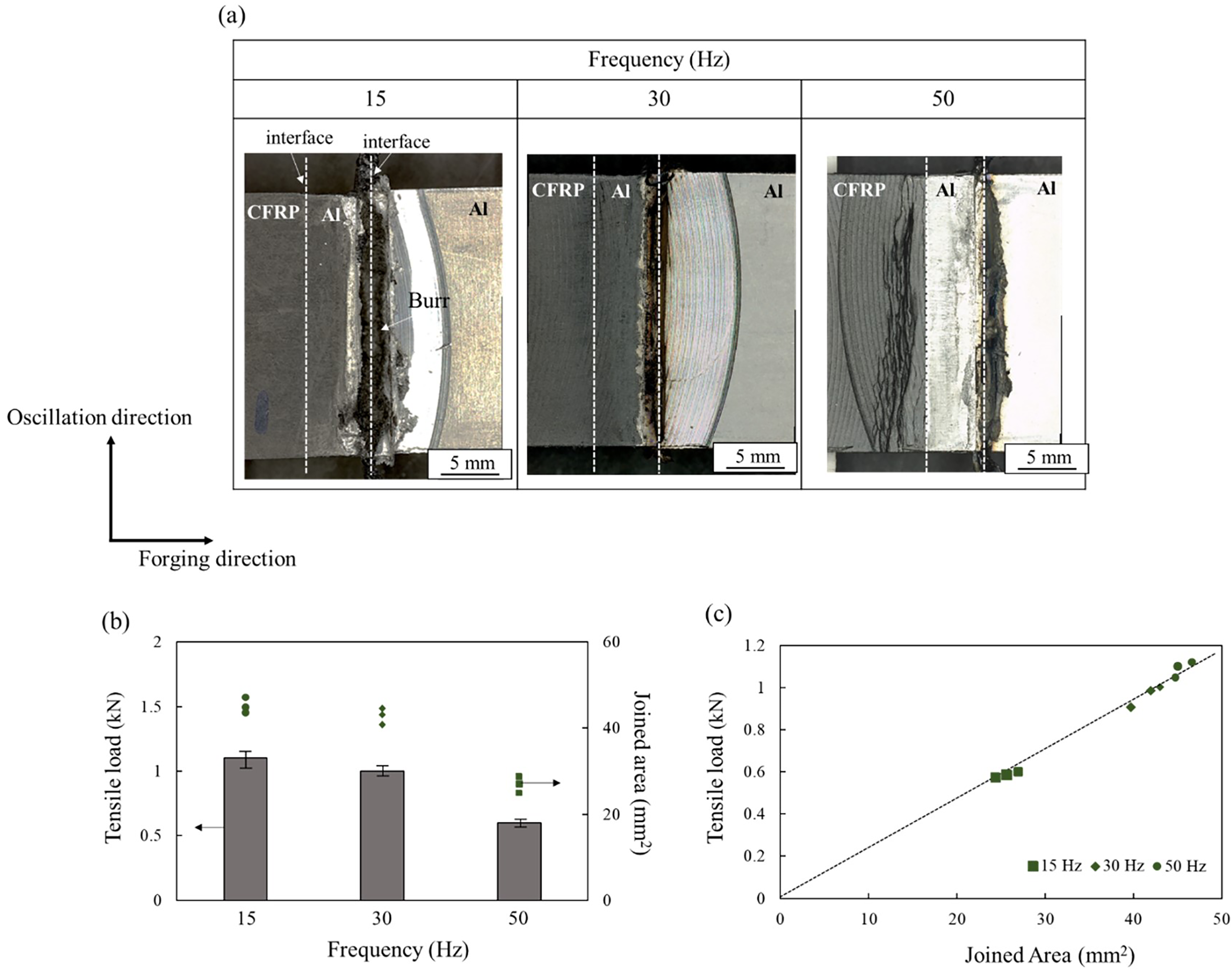
Figure 4 depicts the appearance of the CFRP/A6061-T6 joints at frequencies of 15, 30, and 50 Hz. Burrs were observed between A6061-T6, and both metal-to-metal and CFRP-to-metal butt joints were successfully realized. The metal on the CFRP side was set shorter than the CFRP for tensile testing. Figure 5(a) and (b) presents the temperature histories at 5 and 10 mm from the Al–Al joint interface, respectively, at 15, 30, and 50 Hz. The line at 225 °C in the figure denotes the CFRP melting point, and that at 350 °C indicates the thermal decomposition temperature of the resin matrix in CFRP. The temperature near the joint interface increased rapidly after the onset of linear motion, reached a maximum temperature, and then gradually decreased. The maximum temperatures at 5 mm from the joint interface were 423, 401, and 396 °C at 15, 30, and 50 Hz, respectively, and 311, 252, and 219 °C at 10 mm from the joint interface, respectively. The differences in maximum temperatures between the 5 and 10 mm positions were 112, 149, and 177 °C at 15, 30, and 50 Hz, respectively, indicating that the decrease in temperature escalates with the increasing frequency. This was attributed to the increase in the cooling rate at higher frequencies in LFW, 32 which results in a steeper temperature gradient near the joint interface. The results indicate that a lower frequency is better for increasing the area of the CFRP melt by widening the high-temperature region and that the lowest frequency of 15 Hz is appropriate for obtaining high-strength joints.
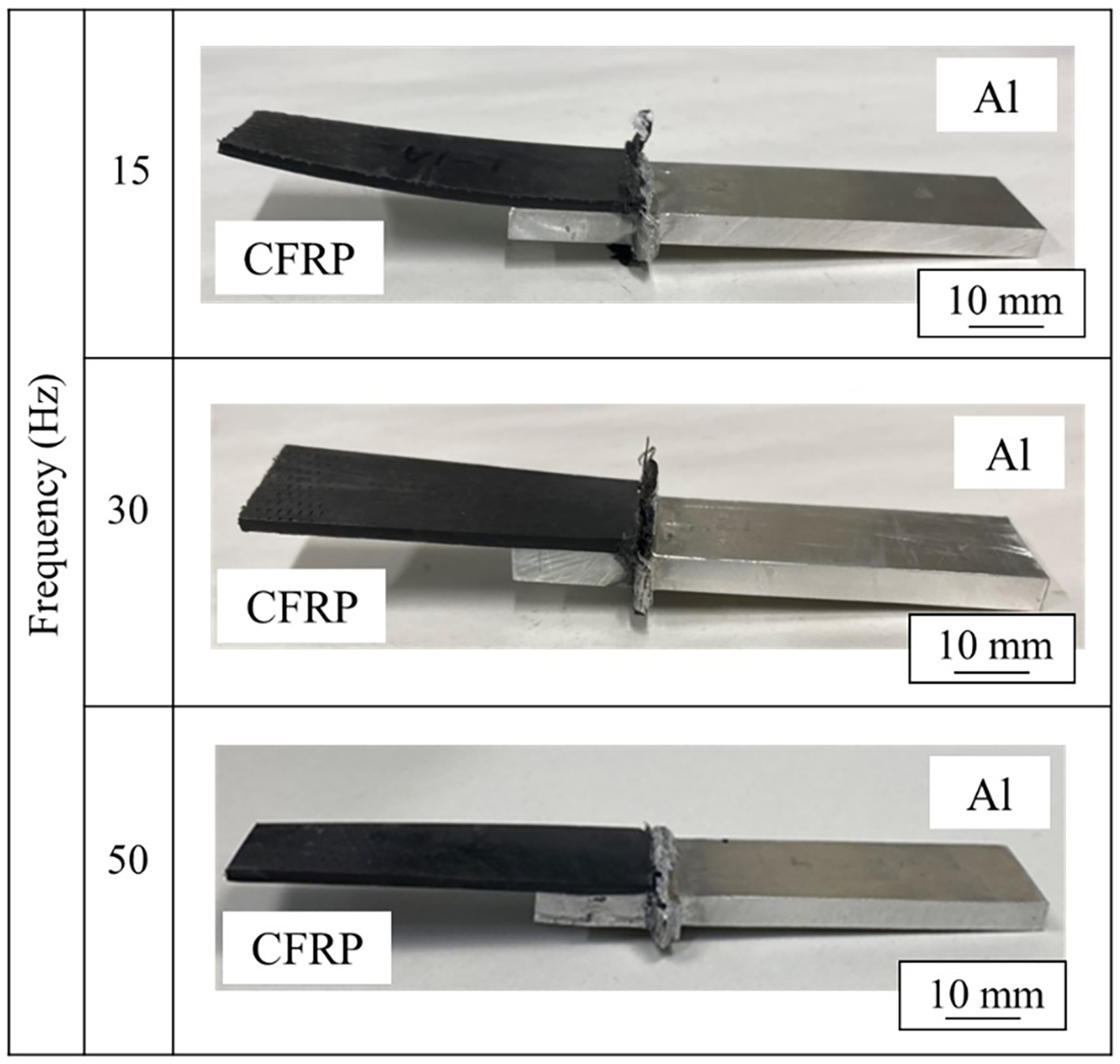
Appearance of the CFRP/Al alloy joints obtained at each frequency using overlap-type thermally conductive LFW.
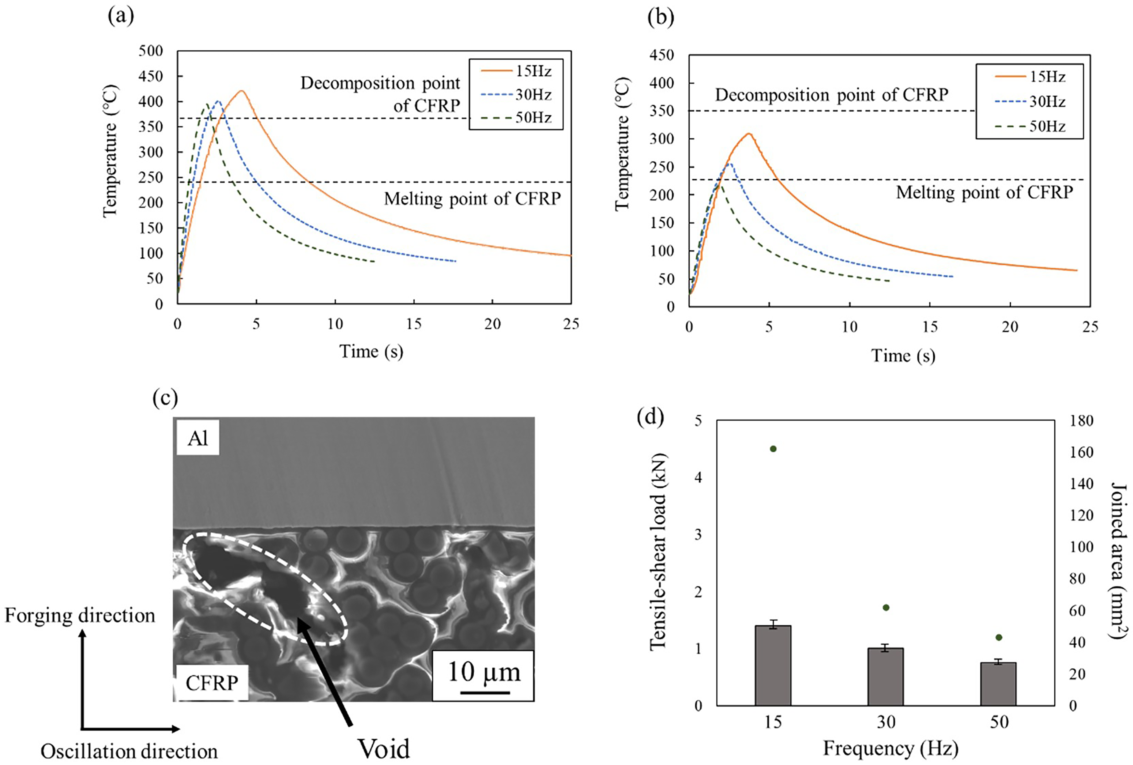
Temperature histories near the joint interface at each frequency. (a) 5 and (b) 10 mm from the joint interface. (c) Microstructure of the joint obtained at 15 Hz. (d) Mechanical properties of the joint obtained using overlap-type thermally conductive LFW.
The maximum temperature exceeds 350 °C (the thermal decomposition temperature of the CFRP resin matrix) under all conditions, and the microstructure image of the joint shown in Figure 5(c) confirms the formation of voids because of thermal decomposition at the joint interface. It has been demonstrated that these voids result from the thermal decomposition of the CFRP resin matrix and the generation of gaseous products, such as CO2 and NH3. Pores within CFRP substantially compromise the material strength of CFRP itself, leading to fractures not at the interface between the CFRP and metal, but within the pores of the CFRP. 13
Figure 5(d) displays the tensile test results of the joints obtained under each condition. The tensile loads of the CFRP/A6061-T6 joints obtained at frequencies of 15, 30, and 50 Hz were 1.4, 1.0, and 0.76 kN, respectively, and the joint areas were 162, 62, and 43 mm², respectively. Compared to the butt joints, the joint area was improved, but the tensile load per joint area decreased (Figure 4). This decrease can be attributed to the reduced strength of the CFRP itself due to the formation of voids and the occurrence of thermal degradation at the joint interface. The tensile shear load increases with decreasing frequency, which is attributed to a wider high-temperature distribution and a larger melted area of CFRP at lower frequencies. Methods to improve joint strength by controlling joint temperature, adjusting pressurization, and managing void formation are explained in the next section.
Effect of applied pressure on the tensile–shear load and microstructures at the fracture of the joint
Figure 6(a) and (b) illustrates the temperature histories at 5 and 10 mm from the joint interface, respectively, under applied pressures of 50, 100, and 150 MPa. The maximum temperatures at 5 mm from the joint interface were 423, 339, and 281 °C at 50, 100, and 150 MPa, respectively, and 309, 283, and 194 °C at 10 mm from the joint interface, respectively. The maximum temperature near the interface was lower under higher applied pressures, which was attributed to the relationship between the applied pressure and joining temperature in LFW.25,26 In LFW, the interface temperature increases with friction whereas the material strength decreases. When the material strength reduces below the applied pressure, the material at the interface cannot withstand the applied pressure, expelling burrs. After the burr expulsion is initiated, the interface temperature is maintained because the heated material sequentially expels burrs. When the applied pressure is high, the material strength at the interface reduces below the applied pressure and expels burrs even if the increase in temperature is low. In other words, the higher the applied pressure, the lower is the interface temperature during joining. At an applied pressure of 50 MPa, the maximum temperature at 5 mm from the joint interface exceeded the thermal decomposition point of the CFRP resin matrix; however, at 100 MPa or higher, the temperature was lower than the thermal decomposition point. The maximum temperature at 10 mm from the interface at 100 MPa exceeded the CFRP melting point, yet the temperature was below the melting point at 150 MPa.
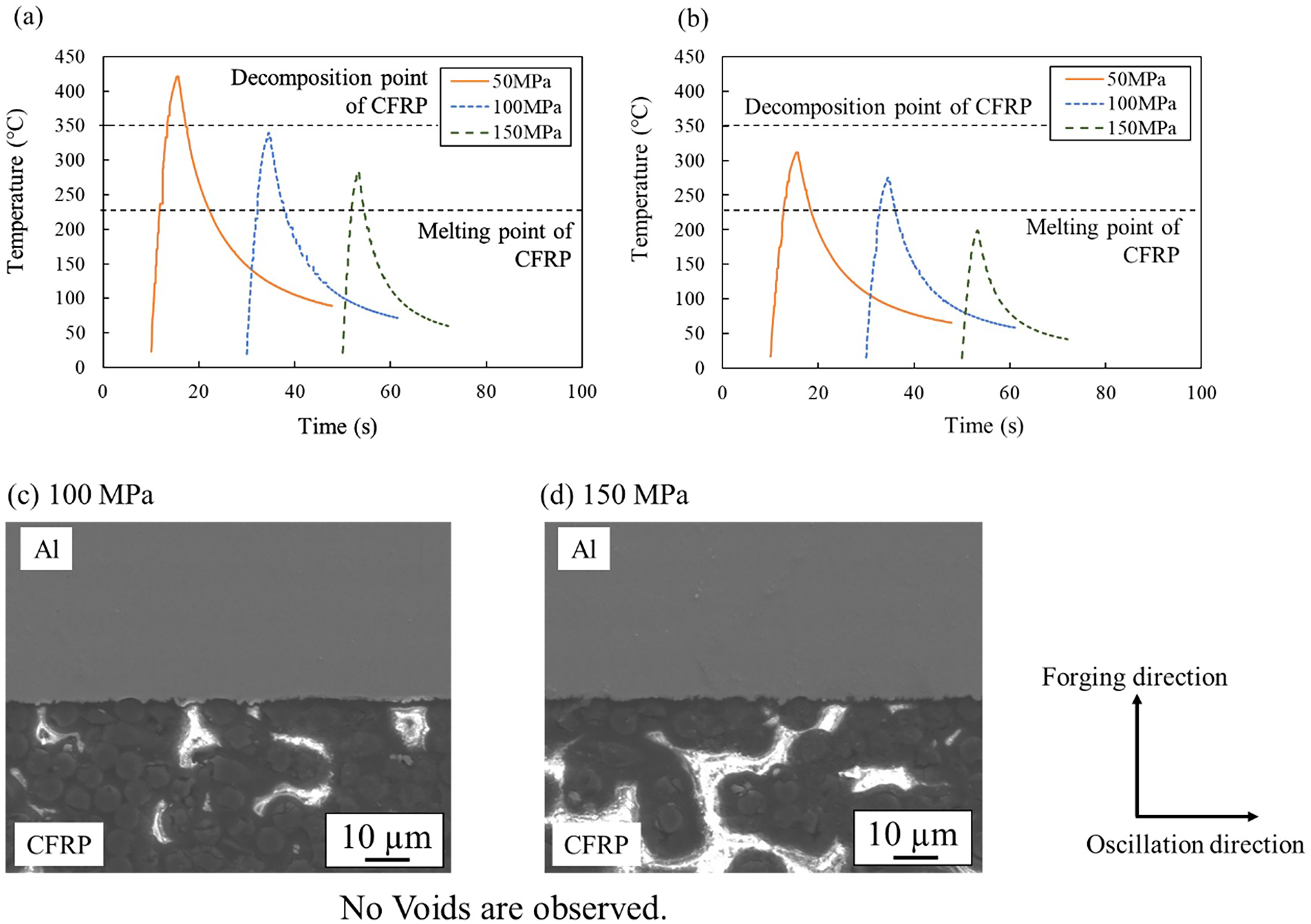
Temperature histories near the joint interface under applied pressure 50,100, and 150MPa; (a) 5 and (b) 10 mm from the joint interface. Cross-sectional micrographs of joints obtained at applied pressures of (c) 100 and (d) 150MPa.
Figure 6(c) and (d) depicts the microstructural images of the joints obtained at 100 and 150 MPa, respectively. The formation of voids caused by thermal decomposition of the CFRP resin matrix was observed at the joint interface obtained at 50 MPa (Figure 5); however, no voids were observed at the joint interfaces obtained at 100 and 150 MPa (Figure 6). This was attributed to the joining occurring at low temperatures, below the thermal decomposition temperature, with the increase in the applied pressure.
Figure 7(a) illustrates the tensile shear load and joint area of CFRP/A6061-T6 joints joined at pressures ranging from 50 to 250 MPa. The maximum tensile shear load was 3.8 kN at 100 MPa and tended to decrease with increasing applied pressure. At pressures above 100 MPa, the maximum temperature at the joint interface decreased as the applied pressure increased, resulting in a reduction in the melt area of the CFRP and a decrease in the tensile shear load. At an applied pressure of 50 MPa, the bonded area was at its maximum, but the bonding temperature was higher than the thermal decomposition temperature of the CFRP resin matrix, leading to void formation and reduced strength.
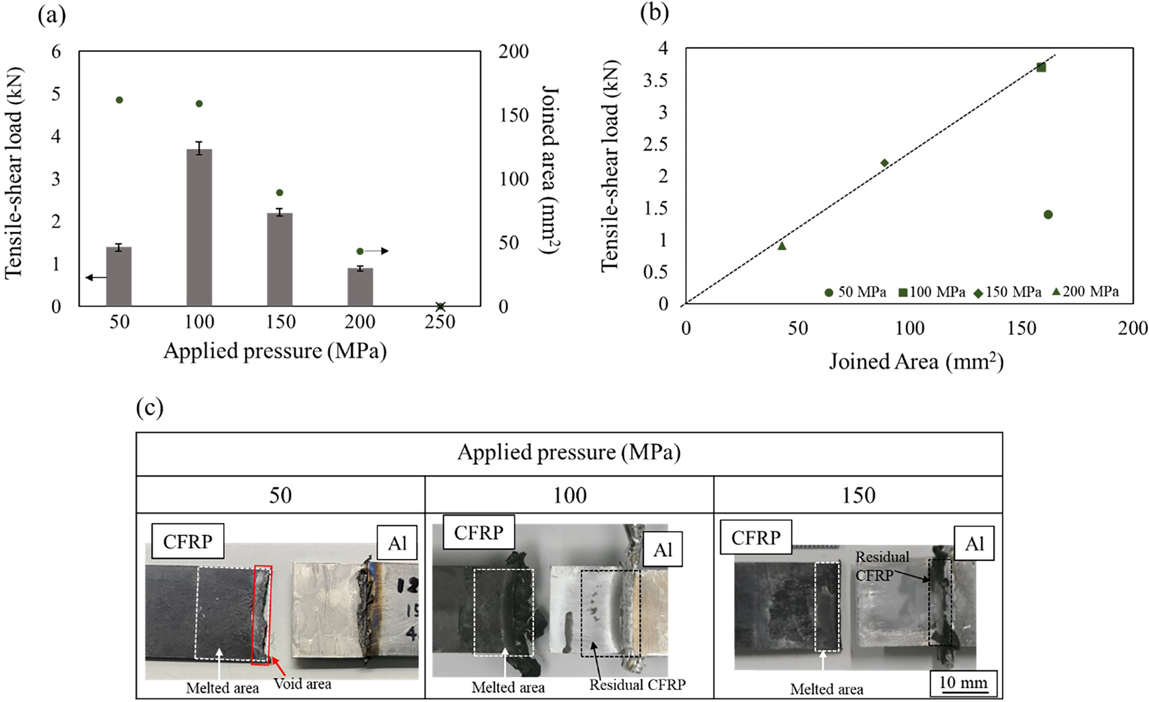
Shear and tensile test results for the joints obtained using overlap-type thermally conductive LFW. (a) Tensile-shear load at applied pressure 50,100, and 150MPa. (b) Correlation between the joined area and tensile load. (c) Macrographs of the fractured surfaces of CFRP/A6061-T6.
Figure 7(b) shows the relationship between the joint area and shear tensile load. Under applied pressures of 100–200 MPa, the tensile shear load was proportional to the joint area, and the tensile strength of the joint was approximately 23 MPa, equivalent to that of the butt joint. Under the condition of 50 MPa of applied pressure, where thermal decomposition of the CFRP resin matrix occurred, the strength of the joint decreased due to the strength reduction of CFRP itself.
Figure 7(c) depicts the macrographs of the fractured surfaces of CFRP/A6061-T6 joints obtained after tensile–shear tests. In all joints, adhesions resulting from the CFRP fracture were observed on the A6061-T6 side under all conditions, and areas of the melted CFRP resin matrix were observed on the CFRP side. Under the 50 MPa condition, a void region was observed in addition to the melted region, with traces of fracture in the CFRP matrix existing in this void region. The molten region at 150 MPa was narrower than that observed at 100 MPa because of the lower joining temperature of the interface at higher applied pressures, which resulted in a narrower high-temperature region.
Conclusions
In this study, the joining of dissimilar materials, namely, CFRP and A6061-T6, via LFW that uses a silane coupling reaction was investigated. In general, friction between light metals and CFRP may result in silanol group exfoliation and present certain challenges in increasing the temperature. Therefore, a thermally conductive LFW was developed, wherein the heat generated by friction between light metals is applied to the metal/CFRP joint. A defect-free joint was obtained by performing butt-type thermally conductive LFW, wherein the light metals and CFRP were butt-jointed. To further expand the joined area, a overlap-type thermally conductive LFW to replace the butt joining was devised. Here, the joining temperature was lowered by increasing the applied pressure, and void formation was successfully suppressed. The temperature distribution near the interface was optimized at an applied pressure of 100 MPa and a frequency of 15 Hz, and a joint with a maximum tensile–shear load of 3.8 kN was obtained. The results provide the basis for the development of a novel process for joining CFRP and metals.
Footnotes
Declaration of conflicting interests
The authors declared no potential conflicts of interest with respect to the research, authorship, and/or publication of this article.
Funding
The authors disclosed receipt of the following financial support for the research, authorship, and/or publication of this article: This work was supported by the JST-Mirai Program, Japan Society for the Promotion of Science (grant number JPMJMI19E5, 19H00826).