
Abstract
The micro-resistance welding between NiTi shape memory alloy and Co-35Ni-20Cr-10Mo alloy (MP35N) wires was investigated to gage the feasibility of their future applications. Welding current and electrode force significantly affected the joint breaking force. The highest joint breaking force (0.99 kgf) at the optimized welding parameter (0.51 kA, 7.500 kg) was accomplished by maximizing the solid-state bonded area and minimizing the heat-affected zone (HAZ). This highest joint breaking force was higher than that of the micro-resistance welded NiTi wire joint reported in previous studies. Furthermore, the cyclic tensile test revealed that the accumulated residual strain of NiTi wire was reduced after welding. This could be attributed to the reduction in the dislocation density through grain growth in the HAZ of NiTi wire during the welding process.
Keywords
Introduction
NiTi alloys with compositions near equiatomic Ni and Ti have unique properties such as excellent shape memory effect, superelasticity, and biocompatibility. 1 Owing to these outstanding properties, NiTi wires are widely used for the fabrication of stents, 2 catheters, 3 and orthodontic archwires. 4 Additionally, NiTi wires are expected to achieve superior and multiple functions by compositing with other medical materials such as MP35N (Co-35Ni-20Cr-10Mo) because MP35N has excellent biocompatibility, 5 high strength, 6 and long fatigue life. 7 For example, a clad wire composed of NiTi and MP35N has been proposed as an imaging guidewire with superelasticity and high mechanical properties. 8 To enhance the versatility of composite design and broaden its range of applications, it is imperative to establish a dependable welding technique for joining NiTi and MP35N wires.
Laser welding has been applied for the dissimilar NiTi-MP35N wire joining. 9 However, there are some challenges to fabricating reliable NiTi-MP35N joints through laser welding. For instance, the joint strength of NiTi-MP35N welds has been reported to decline by forming a brittle Ti-rich phase in the fusion zone (FZ). 9 Although controlling the laser beam intensity and position reduces the cracking of the FZ, it is still challenging to completely avoid the formation of the brittle phase. Furthermore, even if high joint strength is achieved, laser welding sometimes degrades the superelasticity of NiTi wire. The superelasticity of NiTi is derived from the reversible stress-induced martensitic transformation between the B2 cubic phase and B19’ monoclinic phase. 10 Martensitic transformation (B2 to B19’) occurs during loading, while reverse martensitic transformation (B19’ to B2) occurs during unloading. Therefore, the B2 phase needs to be stable at room temperature to exhibit superelasticity. In other words, austenite finish temperature (Af) is required to be lower than room temperature. Af of NiTi alloys is sensitive to the chemical composition and increases with declining Ni concentration. It has been revealed the stable phase in the FZ of Ni-44.2 wt.% Ti at room temperature was converted from austenite to martensite after laser processing due to the evaporation of Ni. 11 In laser welding, the Af in the FZ of the Ni-44.2 wt.% Ti wire joint is reported to increase from 19.7 °C to over 28.0 °C after laser welding. 12 These studies indicate the superelasticity of NiTi wire in the FZ may deteriorate during laser welding due to the Ni evaporation. Therefore, a bonding method that suppresses the FZ formation is desirable to achieve high joint strength and superelasticity.
Nowadays, micro-resistance welding or micro-resistance spot welding is attracting attention in many applications, such as electric-mobility batteries,13–15 solar cells, 16 and power modules. 17 One of the advantages of micro-resistance welding is to achieve joining with low-heat inputs. Micro-resistance welding enables metallurgical bonding accomplished mainly by solid-state bonding for the NiTi-NiTi wire joints. 18 A heat input during micro-resistance welding is strongly influenced by welding current and electrode force. 19 This knowledge suggests that the joint strength and the superelasticity of the welded NiTi wire are expected to be controlled by adjusting the welding current and electrode force. The main objective of this research was to clarify the effects of welding parameters on the joint breaking force of NiTi-MP35N micro-resistance welded joints. Additionally, the impact of micro-resistance welding on the superelasticity of NiTi wire was also evaluated.
Materials and methods
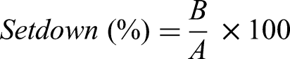
NiTi (Ni-44.7% Ti in wt.%) wire with a diameter of 400 μm and MP35N (Co-34.9% Ni-19.8% Cr-9.7% Mo in wt.%) wire with a diameter of 600 µm were used in this study. NiTi wire was Ni-rich and superelastic at room temperature. These wires were cut into 3 cm lengths and then ultrasonically cleaned with acetone for 15 min. Then, micro-resistance welding was implemented on NiTi and MP35N wires, with a crossed configuration at approximately 90 degrees. A micro-resistance welding system comprised an alternating current controller (Unitek Miyachi, 60 Hz) and a weld head (Unitek Miyachi, Model 80). A pair of Cu-Cr electrodes with a 1 mm-diameter flat tip was used. The welding current and electrode force for the micro-resistance welding were set within 0.40–0.60 kA and 1.725–9.425 kg, respectively. The welding time was fixed as 1 ms. The joint breaking forces of welded samples were measured using a micro-tensile tester (Instron, 5548) at a crosshead speed of 1 mm/min and a gage length of 10 mm, respectively. The welding and tensile tests were performed three times for each welding parameter at room temperature. Wire deformation after welding was evaluated by the parameter of setdown reported in the previous study:
18
Metallographic samples were prepared by cutting the as-welded specimens along the drawing direction of NiTi wires to observe NiTi cross-section since the evolution of NiTi microstructure should be paid more attention. The cut samples were cold mounted using epoxy resin and eventually polished with 1 μm diamond suspension. Etching was performed with Kroll's reagent (2–4% HF, 5–7% HNO3, and 89–93% H2O by volume) for 60 s. Optical microscopy (OM) and field emission scanning electron microscopy (SEM) (Zeiss Ultra Plus) were employed to observe the microstructure. Energy-dispersive X-ray (EDX) spectroscopy was employed to analyze the composition. The grain size was determined by the line intercept method. Crystallographic orientations were analyzed by electron backscatter diffraction using SEM (JEOL JSM 7000). Vickers hardness was measured using a micro-hardness tester (Clemex, CMT) to evaluate mechanical properties near bonded areas. The indented force and dwell time were set as 200 gf and 10 s, respectively. Superelasticities of NiTi wires before and after micro-resistance welding were evaluated by room temperature cyclic tests using the micro-tensile tester with a crosshead speed of 1 mm/min, the number of cycles of 50, and a gage length of 10 mm, respectively.
Results and discussions
Optimization of micro-resistance welding parameters
The joint breaking forces of welded samples with various welding currents and electrode forces are shown in Figure 1(a). The highest joint breaking force was 0.99 kgf on average at the optimized parameters of 0.51 kA welding current and 7.500 kg electrode force. The fracture occurred at the joint interface between NiTi and MP35N wires. When the welding current was excessively low (0.40 kA), or the electrode force was excessively high (9.425 kg), there was no reliable bonding between NiTi and MP35N wires. Sections “The effects of the welding current on the joint breaking force” and “The effects of the electrode force on the joint breaking force” discussed in detail how welding parameters impact both joint breaking force and the evolution of the microstructure during welding.

(a) Joint breaking forces of NiTi-MP35N joints welded by various welding currents and electrode forces. (b) Cross-sectional image of the welded NiTi and MP35N wires with the optimized parameters (Welding current: 0.51 kA, Electrode force: 7.500 kg). (c) SEM image and EDX results of a flash. (d) SEM image and EDX results of the interfacial layer formed between NiTi and MP35N. SEM: scanning electron microscopy; EDX: energy-dispersive X-ray.
The OM image of the cross-section of the bonded area with the optimized parameter is shown in Figure 1(b). The clear FZ was not observed at the joint interface. The heat-affected zone (HAZ), where grain growth occurred, was observed in NiTi wire near the joint interface. The setdown of the NiTi-MP35N joint with the optimized parameter was 16.3%. Tam et al. reported that joint breaking force of crossed micro-resistance welded NiTi wires with wire diameters of 400 μm was 0.51 kgf when the setdown was 20.0%. 18 To evaluate the joint breaking force based on the same base material diameter, the estimated joint breaking force in the previous work was calculated to be 0.77 kgf, by converting one wire diameter into 600 µm. The results find that the optimized joint breaking force of the NiTi-MP35N wire joint in this work is higher than that of the NiTi-NiTi joint. In the NiTi-MP35N joint, flashes were observed at the edge of the joint interface as shown in Figure 1(b). However, no flashes were observed around the edge of the bonded area of the NiTi-NiTi joint at a similar setdown. 18
There are several mechanisms reported for micro-resistance welding: fusion welding, 20 a hybrid of fusion welding and solid-state bonding, 19 and a combination of brazing and solid-state bonding. 21 In this research, joinning with the optimized parameter would be eventually achieved through solid-state bonding because no obvious FZ existed as shown in Figure 1(b). On the other hand, surface melting and squeezing-out play a substantial role in exposing fresh metal surfaces required to form joints, as reported by a study on micro-resistance welding of crossed Ni-Ni wires. 19 The SEM and EDX line scanning result of the flash in Figure 1(c) show that Ni and Ti from NiTi wire, and Co, Cr, and Mo from MP35N wire were all detected. Additionally, the higher oxygen concentration was detected in the flash than in NiTi and MP35N wires. This result implies that the wire surfaces, including oxidation passivation layers on NiTi and MP35N wires, were melted at the joint interface and squeezed out as flashes. The melting points of NiTi and MP35N are approximately 1310 °C and 1440 °C, respectively. Therefore, once sufficient heat input was applied, both wire surfaces could be melted and squeezed out, especially considering the higher contact resistance at the initial welding stage. Eventually, solid-state bonding was achieved at the entire interface by applying the electrode force between fresh metal surfaces of NiTi and MP35N wires. Figure 1(d) illustrates the backscattered electron image and EDX results of the joint interface between NiTi and MP35N wires. There were no visible voids at the joint interface, and a thin interfacial layer with a maximum thickness of about 500 nm was observed. Although the impacts of the interfacial layer on the joint strength are not clear, it is thought that the interfacial layer is less harmful to the joint strength when it is less than 500 nm because enhanced joint strength was achieved. The interfacial layer may be intermetallic compounds. The EDX line analysis demonstrates that Ni, Ti, Co, Cr, Ti, and Mo contained in NiTi and MP35N were detected in this layer. The concentrations of these elements changed continuously within the layer, and no intermetallic compounds with stoichiometric compositions were observed. However, due to the insufficient spatial resolution of SEM-EDX, it was challenging to determine if the interfacial layer is an intermetallic compound. Further analysis is needed to identify phases of the interfacial layer. From an industrial point of view, flashes should be removed by the machining process, such as micro-grinding, to prevent them from falling off during use.
The effects of the welding current on the joint breaking force
Figure 2(a) shows the relationship between the joint breaking force, welding current, and setdown at an electrode force of 7.500 kg. The joint breaking force increased as the welding current increased from 0.40 kA to 0.51 kA and decreased as it rose from 0.52 kA to 0.60 kA. Setdown increased with the increase of welding current from 0.40 kA to 0.60 kA. The large setdown indicates the large joint area and also the small cross-sectional area of the bonded NiTi wire (thinning/damage of NiTi base metal (BM)). Thus, enhancing the joint area and suppressing the cross-sectional area reduction and mechanical degradation of the welded NiTi wire is needed to achieve the high joint breaking force. The mechanical degradation was caused by the HAZ formation. The scale of the HAZ in the welded NiTi wire at 0.40 kA (Figure 2(b)) and 0.51 kA (Figure 2(c)) was smaller than at 0.60 kA (Figure 2 (d)). Vickers hardness of the HAZ in NiTi wire (262–274 HV) was lower than that in NiTi BM (330 HV) (Figure 3). The hardness of the HAZ at 0.51 kA was maintained higher than that at 0.60 kA. These results indicate the highest joint breaking strength was achieved by maximizing the joint area and minimizing HAZ formation and HAZ hardness degradation at 0.51 kA.
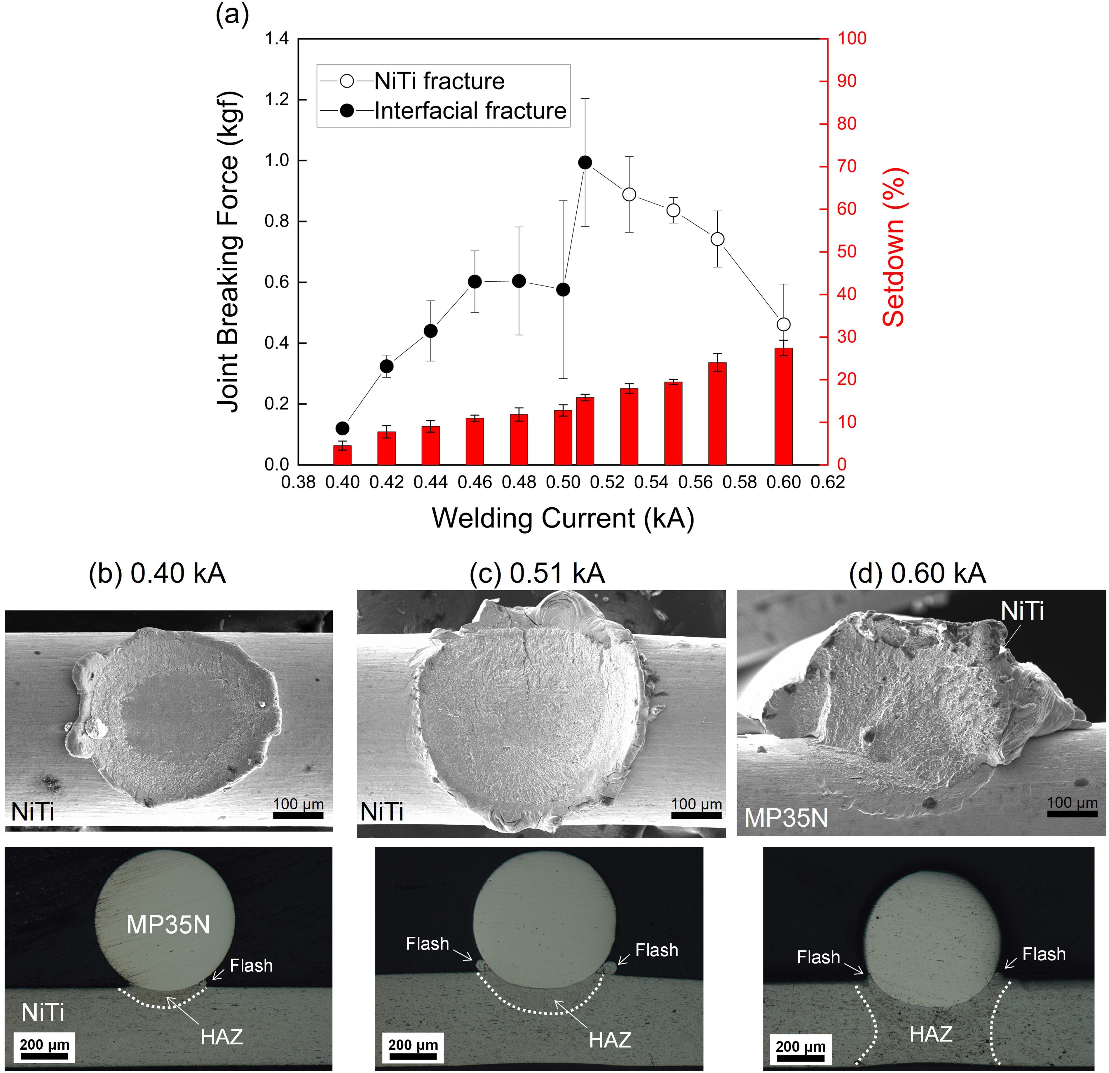
(a) Relationships between the joint breaking force, welding current, and setdown at an electrode force of 7.500 kg. Fracture surfaces after tensile test and cross-sectional images of bonded areas at the welding current of (b) 0.40 kA, (c) 0.51 kA, and (d) 0.60 kA.
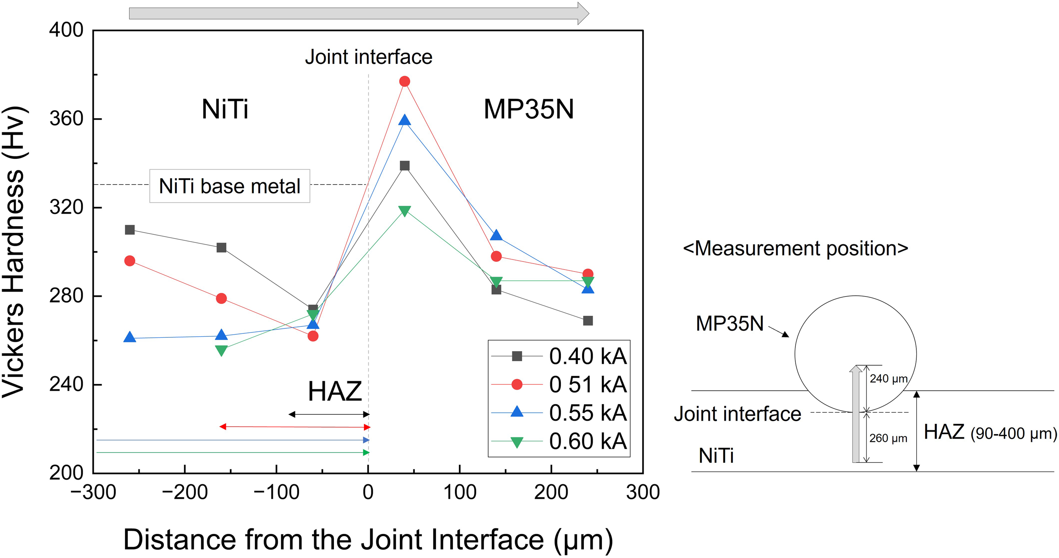
Vickers hardness near the joint interface at the welding current of 0.40–0.60 kA. (Electrode force: 7.500 kg).
Figure 4(a) shows the microstructure of the HAZ of NiTi wire obtained with the optimized welding parameter (0.51 kA, 7.500 kg). The average grain size of NiTi wire gradually coarsened from 2.9 μm to 3.9 μm as it approached from 25 μm to 10μm from the joint interface. This result supports that the grain growth occurred near the joint interface, leading to HAZ softening. Similar behavior has been observed in micro-resistance welding of the crossed NiTi-NiTi wires. 18 It is noted that the hardness of MP35N wire near the joint interface (319–377 HV) was higher than the MP35N BM (269 HV), unlike NiTi (Figure 3). MP35N has a face-centered cubic structure and low stacking fault energy. The stacking fault energy of MP35N (Co-35.3 wt.% Ni-18.9 wt.% Cr-10.5 wt.% Mo) is reported as about 9 mJ/m2 at room temperature. 22 Thus, MP35N would exhibit a high work hardening rate due to dislocation and deformation twins introduced during plastic deformation.23,24 Figure 4(c) shows the inverse pole figure maps and Kernel average misorientation maps of the welded MP35N wire side near the bonded interface. The inverse pole figure maps illustrate the grain size of MP35N near the joint interface was roughly the same at the center region (Figure 4(b)), even though the grains were elongated in the X-direction by undergoing compressive deformation induced by the electrode force. Kernel average misorientation maps present that the dislocation density near the joint interface was higher than near the center region. In addition, some dislocations were linearly aligned in specific directions within the grains as indicated by the arrows. These aligned dislocations suggest that slip deformation and deformation twinning occurred. 25 Therefore, the high hardness of the welded MP35N wire near the joint interface should be due to the work hardening.
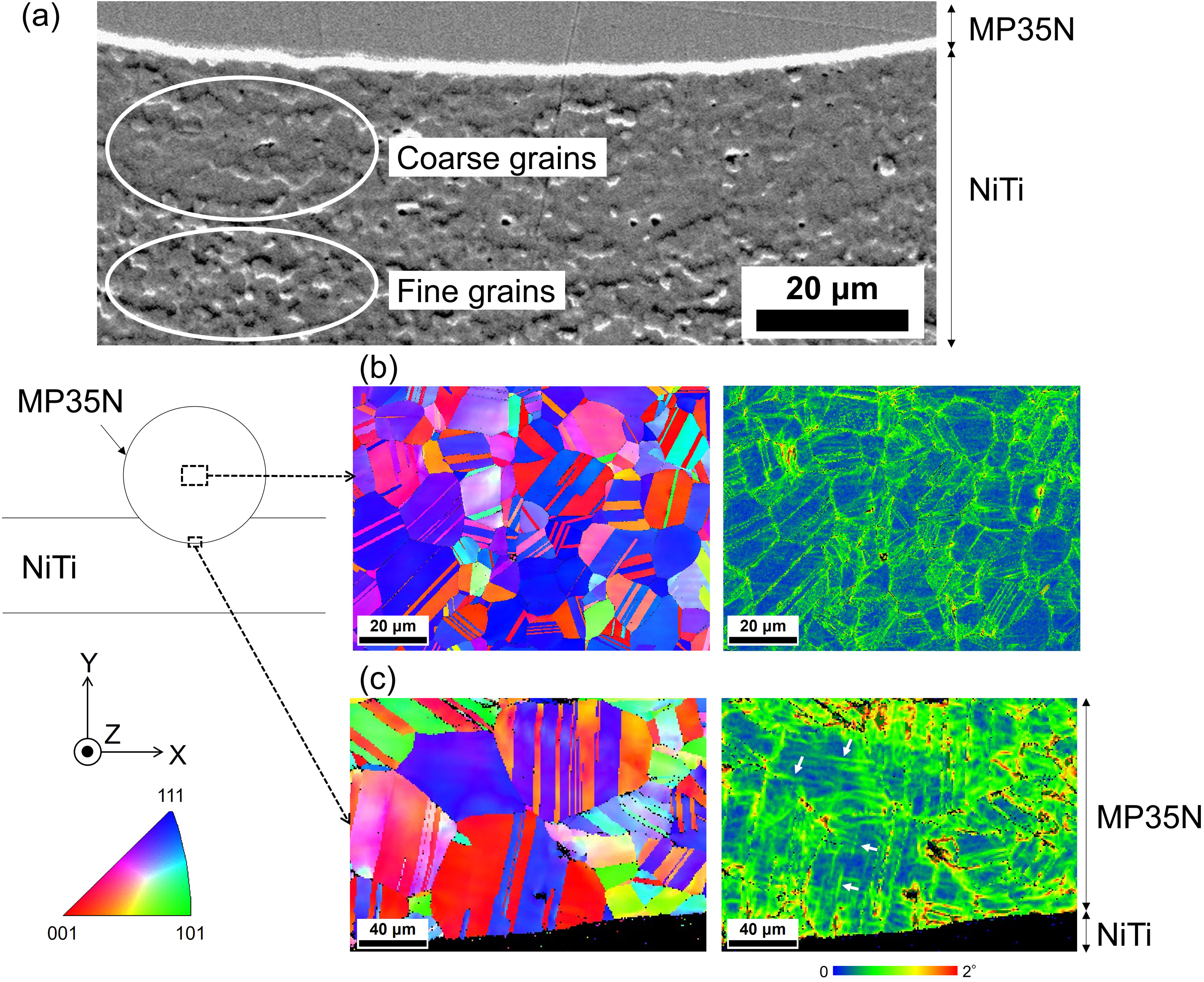
(a) Microstructure of NiTi wire near the joint interface welded with the optimized welding parameter. Inverse pole figure maps (Z-direction) (Left side) and Kernel average misorientation maps (Right side) of the welded MP35N wire: (b) center region and (c) bonded area.
This difference in dynamic microstructure evolution between NiTi and MP35N wires should also be attributed to their thermal conductivity and recrystallization temperature differences. The thermal conductivity of MP35N (12.4–18.9 W / mK) is higher than NiTi (8.9–13.7 W / mK) at the temperature of 50–300 °C.26,27 Therefore, MP35N wires are cooled more quickly than NiTi wires during welding. In addition, the recrystallization temperature of 30–50% cold worked Ti-50.8 at.% Ni annealed for 60 min is reported to be approximately 450 °C, 28 while the recrystallization temperature of 48% cold-drawn MP35N annealed for 60 min is about 810 °C. 25 Consequently, NiTi wire near the joint interface is considered readily grain growth, leading to softening, while MP35N wire is difficult, resulting in work hardening. Notably, the high work hardening ability of MP35N should effectively expel molten metal as flashes from the joint interface during welding.
The effects of the electrode force on the joint breaking force
Figure 5(a) shows the relationships between the joint breaking force, electrode force, and setdown at a welding current of 0.51 kA. The joint breaking force and setdown gradually increased with electrode forces from 1.725 kg to 7.500 kg. This result presents that the highest joint breaking force at 7.500 kg was achieved by enhancing the bonded area. In addition, the fracture mode was changed from the NiTi fracture to the interfacial fracture as the electrode force increased. This fracture transition would be related to the HAZ area and hardness of the HAZ. The HAZ area at an electrode force of 1.725 kg was large (Figure 5(b)), whereas the HAZ areas were small when electrode forces were 5.575 kg (Figure 5(c)) and 7.500 kg (Figure 5(d)). The hardness of the HAZ in NiTi wires was 240–260 HV when the electrode force was lower than 3.650 kg; it was 260–280 HV when the electrode force was over 5.575 kg (Figure 6). These results indicate that decreasing HAZ areas and preventing HAZ softening result in the fracture mode transition from the NiTi fracture to the interfacial fracture at the high electrode force.
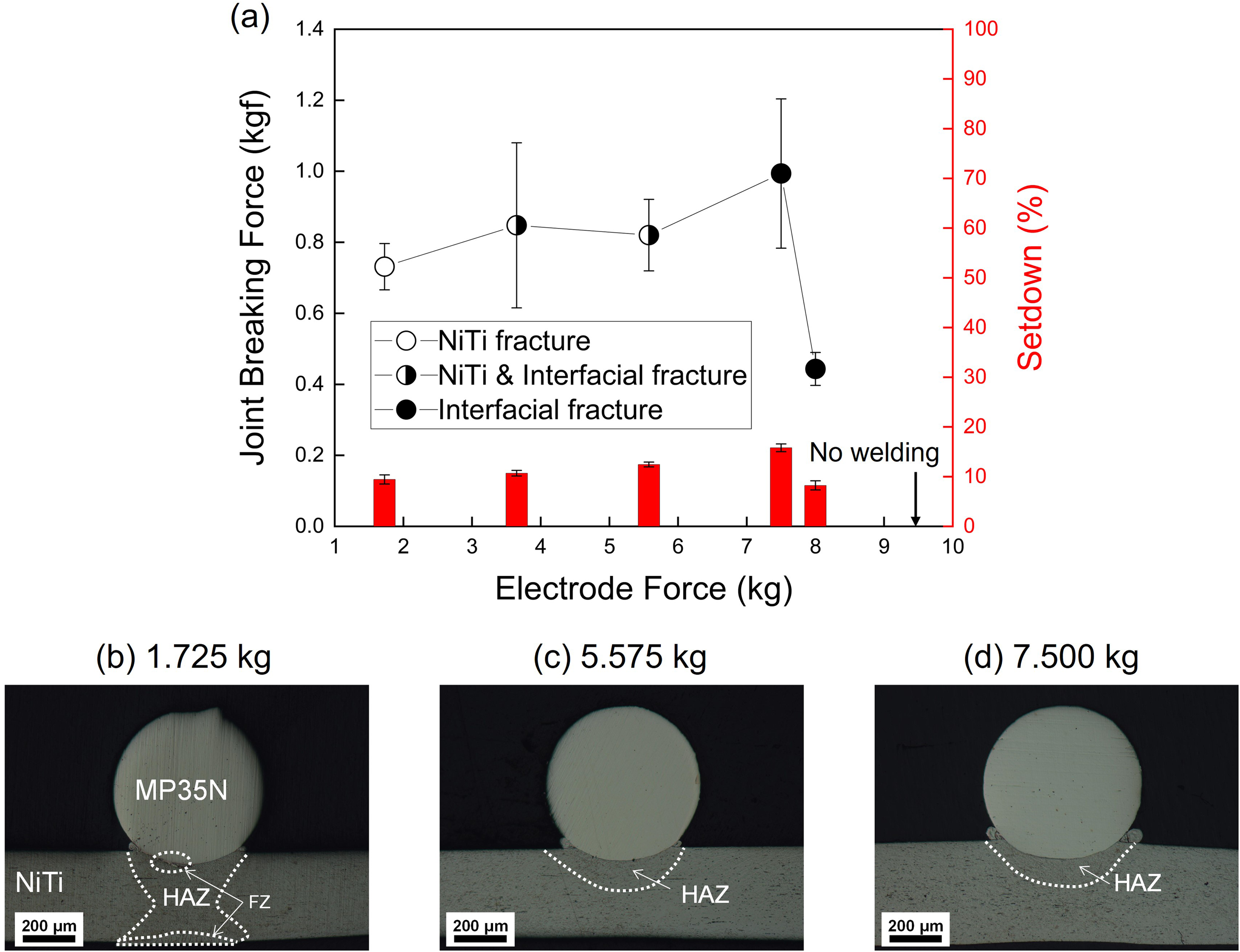
(a) Relationships between the joint breaking force, electrode force, and setdown (Welding current: 0.51 kA). Cross-sectional images of bonded areas at the electrode force of (b) 1.725 kg, (c) 5.575 kg, and (d) 7.500 kg.
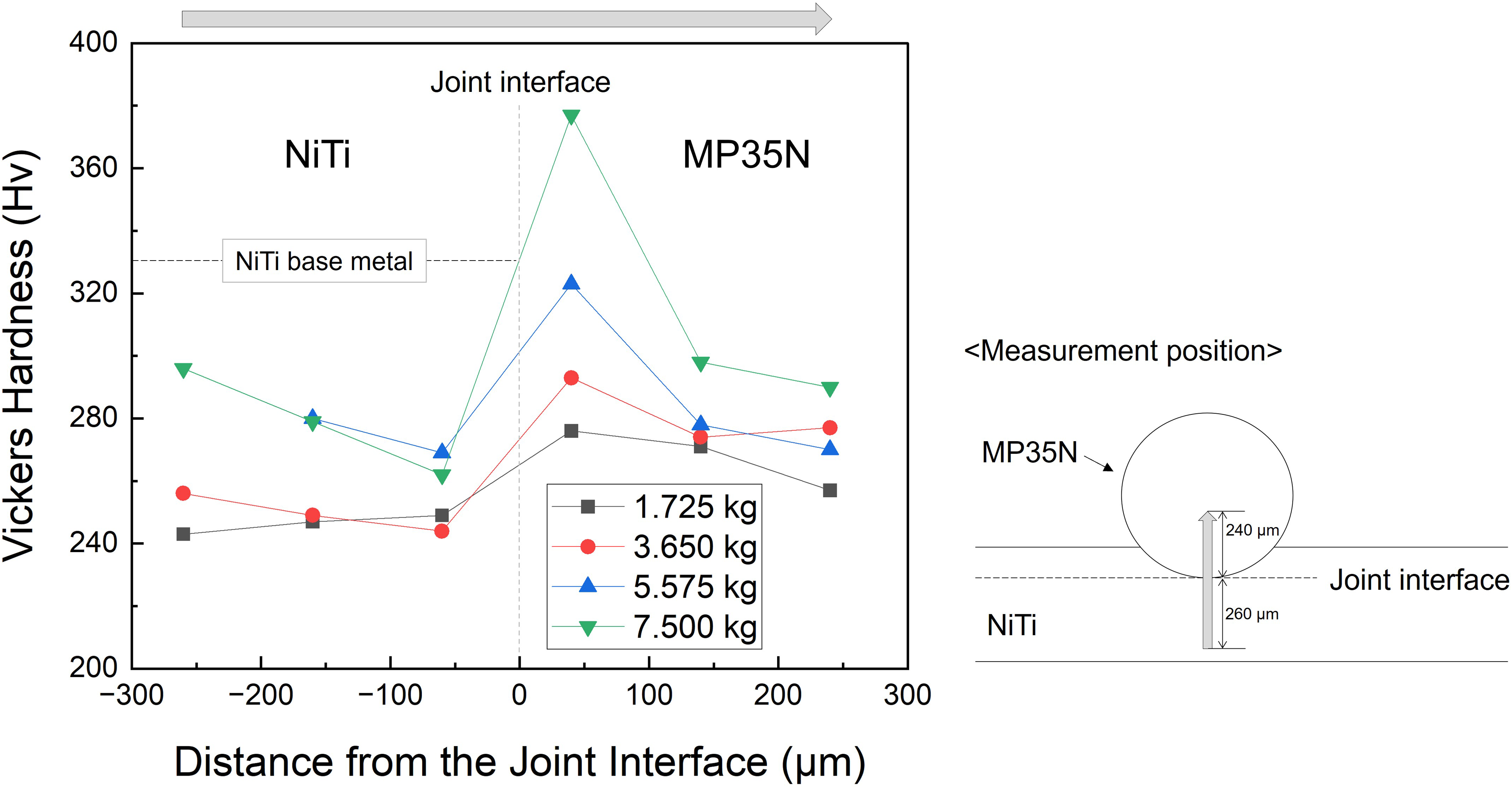
Vickers hardness near the joint interface at the electrode force of 1.725–7.500 kg. (Welding current: 0.51 kA).
The hardness in the HAZ of NiTi wire depends on the grain size in the HAZ, as described in Figure 4(a). It has been reported that higher electrode force facilitates the softening of irregular protrusions on the electrode and workpiece surface at the early stage of welding, which increases contact areas and decreases dynamic resistance.29,30 Hence, it is considered that low electrode force of less than 3.650 kg causes grain growth in the HAZ due to the high heat inputs, whereas high electrode force of more than 5.575 kg can prevent grain growth in the HAZ by reducing heat inputs. The joint breaking force and setdown declined at the electrode force of 8.000 kg because of insufficient heat input, and no successful joints were fabricated at an excessive electrode force of 9.425 kg.
The mechanism of micro-resistance welding of the NiTi and MP35N wires
A schematic illustration of the micro-resistance welding mechanism at the optimized parameter (0.51 kA, 7.500 kg) is presented in Figure 7. The optimized welding process is divided into four stages: (i) contacting, (ii) wire surface melting, (iii) squeezing-out, and (iv) solid-state bonding. In the contacting stage, heat is generated at the joint interface and dissipates into NiTi and MP35N wires. In the wire surface melting stage, the wire surfaces of both NiTi and MP35N wires, including oxidation passivation layers, are melted. Subsequently, the softened HAZ forms in NiTi wires, while work hardening occurs in MP35N wires. After that, molten metal is removed as flashes by applying the electrode pressure. Eventually, solid-state bonding is achieved through metallic bonds between fresh surfaces of NiTi and MP35N wires because there are no barriers between the two metals, and an interfacial layer forms at the joint interface.
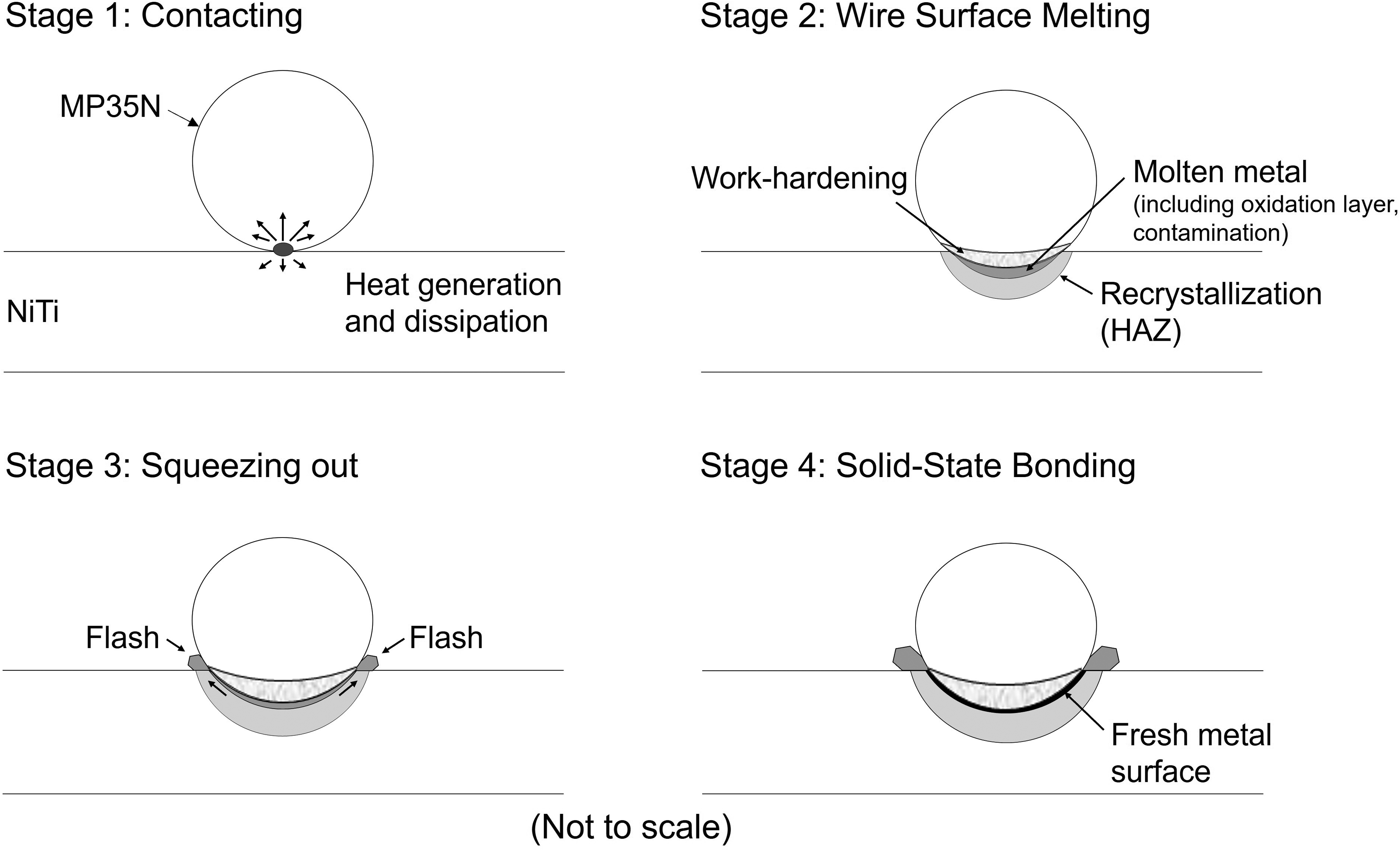
Schematic of micro-resistance welding mechanism of the crossed NiTi and MP35N wires welded by the optimized welding parameter.
The effects of micro-resistance welding on superelasticity of NiTi wires
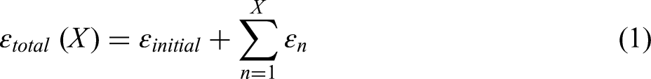
The cyclic test results of the NiTi BM wire and the welded NiTi wire with the optimized parameter are shown in Figure 8(a) and (b) respectively. Residual strains accumulated as cycles increased. The total residual strain of NiTi BM was 1.07%, and that of welded NiTi was only 0.99% after 50 cycles. The residual strain of NiTi wire was reduced by 7.5% through micro-resistance welding. On the other hand, laser welding increased the residual strain by approximately 66% in NiTi-NiTi joints since the stress-induced martensitic transformation easily occurred in the FZ. 31 This indicates that micro-resistance welding reduced residual strains because micro-resistance welding rarely accompanied the FZ formation. In addition, such a low residual strain of micro-resistance welding should also be attributed to the reduction in the dislocation density of NiTi wire.
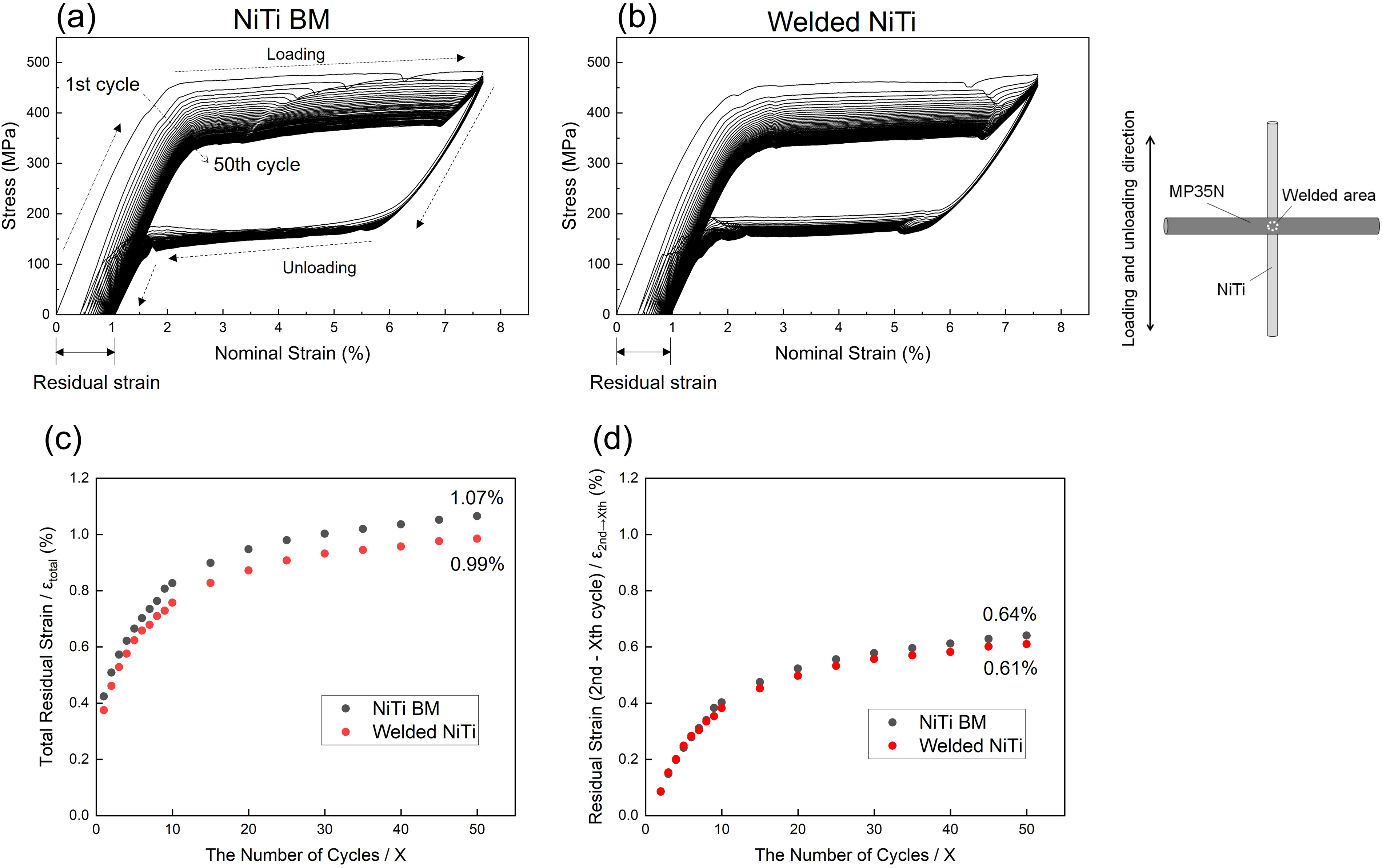
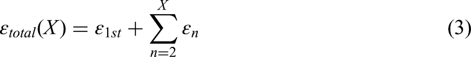
Cyclic test results of (a) NiTi BM and (b) welded NiTi. Accumulated residual strains of NiTi BM and welded NiTi: (c) total residual strain (
The deterioration of the superelasticity of NiTi is caused by a residual strain introduced during the cyclic tensile and before the cyclic tensile tests. The first factor is the accumulated residual strain with increasing cycles, originating from the increased dislocation density, and the residual B19’ phase after the reverse martensitic transformation.
32
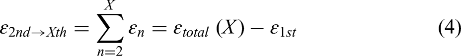
The second factor is mainly related to the dislocations pre-existing in the NiTi BM, which were created during wire manufacturing processes (i.e. drawing). To separate the effects of these two factors on the residual strain of NiTi wires, residual strain data were analyzed. A total residual strain after the cyclic tensile test is given by the relation:

Conclusions
Micro-resistance welding was implemented for crossed NiTi and MP35N wires. The effects of welding parameters on joint breaking forces and microstructure evolution were investigated. Additionally, the influence of micro-resistance welding on the superelasticity of NiTi wire was examined. The significant results of this research are listed as follows.
The highest joint breaking force (0.99 kgf) was obtained using the optimized welding parameter: a welding current (0.51 kA) and an electrode force (7.500 kg), due to the increased solid-state bonded area and minimized HAZ. The micro-resistance welding mechanism of NiTi-MP35N wires under the optimized welding parameter was the melting of surfaces of NiTi and MP35N, and subsequently squeezed molten metal and oxides as flashes to realize solid-state bonding. The superelasticity of NiTi wire could be enhanced by micro-resistance welding because of the reduction of dislocation density in the HAZ.
Footnotes
Data availability statement
The data that support the findings of this study are available from the corresponding author upon reasonable request.
Declaration of conflicting interests
The authors declared no potential conflicts of interest with respect to the research, authorship, and/or publication of this article.
Funding
The authors disclosed receipt of the following financial support for the research, authorship, and/or publication of this article: This work was supported by the Canada Research Chairs, Nippon Steel Corporation, Natural Sciences and Engineering Research Council of Canada,