
Abstract
Friction stir spot welding (FSSW) is a promising joining method for advanced high-strength steels. Understanding the factors influencing the failure behaviour of FSSW joints is crucial for using this method in the automotive industry. This study addresses the role of rotational speed on the microstructure and hardness across the weld, as well as on the geometrical features and failure behaviour of ultrafine carbide-free bainitic steel FSSW joints. Increasing the rotational speed from 600 to 2000 rpm is identified as effective in eliminating the hook feature. A small effective thickness (320 μm), accompanied by a sharply upward hook, renders the weld susceptible to partial pullout failure at 600 rpm, beyond which interfacial failure emerges as the prevailing failure mode. A rotational speed of 1000 rpm is sufficient to develop an adequate bonding area with fine martensite, resulting in the maximum failure energy.
Introduction
The application of advanced high-strength steels (AHSSs) in modern vehicle bodies makes the use of thinner gauges and accordingly, mass reduction possible, resulting in lower fuel consumption while improving passenger safety. Carbide-free bainitic (CFB) steels, known as third-generation AHSSs, contain an interwoven mixture of nano/ultrafine bainitic ferrite platelets, in nano or ultrafine range, and residual austenite. CFB steels offer a unique combination of high yield strength, good ductility and energy absorption capacity, making them a promising candidate for safety-critical components in automotive body, such as pillars.1–4
CFB steels are recognised as being difficult to weld using fusion procedures owing to formation of coarse martensite with a dendritic solidification structure, cracking, and microsegregation of alloying elements in the fusion zone, all of which degrade the joint's mechanical performance.
5
Hence, the weldability of this specific grade of bainitic steels poses significant challenges for its commercialisation in the automotive industry. To address these issues, two approaches reported in the literature are based on obtaining a bainitic microstructure throughout the welded joint, as described below.
Regeneration technique: This approach relies on welding the bainitic steel, followed by controlled cooling of welded joint to a temperature below the Bs, and isothermal holding for a sufficient duration to allow fusion and reaustenitised zones to transform into bainite.5,6 Based on the fact that plastic deformation of primary austenite is an effective way to accelerate bainitic transformation, the rotary impacting trailed welding method has been suggested to reduce regeneration time. In this method, welding and rotary impacting proceed concurrently, introducing plastic deformation into austenitised regions and in turn shortening the bainitic reaction period.
7
Another method to speed up the regeneration treatment involves refining austenite grains through static recrystallisation utilising a two-pass impacting trailed welding process.
8
Post-weld heat treatment (PWHT): In this method, after welding steel in as-delivered state and cooling to ambient temperature, the welded joint is subjected to austenitisation and austempering heat treatment.5,6
Even though both the regeneration and PWHT methods offer potential for avoiding hot or cold cracking and achieving acceptable mechanical properties,5,6 they do not appear to be commercially viable approaches due to significant costs associated with additional equipment and heat treatment. In this respect, seeking a reliable economic solution is of crucial importance.
Given their high strength and limited formability relative to lightweight alloys like aluminium, the application of friction stir welding (FSW) and friction stir spot welding (FSSW) to AHSSs remains challenging. However, as solid-state joining methods, these processes allow for mitigating issues commonly encountered in fusion-based joining of AHSSs, such as solidification-related defects and formation of coarse brittle martensite in weld zone, while remarkably reducing energy consumption. Such advantages, accordingly, make FSSW a potential alternative to resistance spot welding (RSW) in the automotive sector.9,10 In this context, Ramakrishna et al. 11 subjected CFB steel to FSW and observed that enhancing the rotational speed was associated with a reduction in the retained austenite content and fragmentation of bainitic laths, leading to more pronounced hardening in the stir zone (SZ). Moreover, it was found that employing tempering on friction stir welds made it possible to reach a comparable hardness in the SZ relative to base metal (BM), mainly because of coarsening of bainitic laths. However, their studies did not provide any data regarding mechanical properties of the welds. The feasibility of FSSW for joining an ultrafine CFB steel has been recently investigated by Kabirmohammadi et al.12,13 for the first time. It has been shown that despite the formation of a predominantly martensitic microstructure within the weld zone, promising mechanical performance can be achieved, with the peak load exceeding American Welding Society (AWS) minimum requirement. This has been attributed to the unique ability of FSSW process in refining austenite grains through dynamic recrystallisation (DRX), thereby forming a refined martensitic structure that impedes failure.12,13 The findings of these studies provide an effective strategy for addressing inferior fusion weldability of this class of steels, eliminating the need for post-weld processing.
Concerning FSSW of other AHSS grades, for instance, Wang et al. 14 evaluated the influence of rotational speed on double-sided FSSW joints of 1.5 GPa quenched and tempered martensitic steel. They noted that at a lower rotational speed, the SZ featured a ferritic and pearlitic microstructure, and the weld underwent interfacial failure owing to the presence of oxides along welding interface. On the contrary, a concomitant increase in cooling rate and primary austenite grain size with increasing the rotational speed facilitated martensite development, leading to improved mechanical response. Additionally, severe plastic deformation and material flow at a higher rotational speed contributed to dispersion of oxides, thereby producing a sound welding interface and favouring pullout failure. A work on FSSW of DP1180 showed that the developed oxide film throughout the SZ driven by weak bonding at the sheets interface, provided an easy crack propagation path, causing interfacial fracture and inferior mechanical performance. 15
In publications dealing with FSSW of CFB steels, the roles of rotational speed 12 and dwell time 13 were evaluated. In the study on rotational speed, 12 strengthening mechanisms across different weld zones and global performance of joint in terms of failure load were analysed. However, several key aspects of FSSW of CFB steels remained unexplored. Specifically, no results were reported in literature regarding the influence of rotational speed on: (1) weld geometry, like the hook defect which can considerably compromise joint integrity and is a major concern for joint mechanical performance16,17; (2) failure energy, which reflects the capability of welds to absorb energy under impact loading conditions such as those encountered during crash accident 18 ; (3) failure mode transition and crack propagation path, being of importance when discussing joint mechanical performance; and (4) microstructure and hardness in different weld zones. To address these gaps, the present work establishes a correlation between rotational speed, geometrical and microstructural weld attributes, and failure behaviour of ultrafine CFB steel friction stir spot welds in terms of failure mode and failure energy. Another focus is on hardness distribution across the weld under various rotational speeds.
Experimental procedures
The test material was a 1.1 mm-thick ultrafine CFB steel with the chemical composition, microstructural features and mechanical properties given in Table S1 (Supplemental document, Section 1). Details of the manufacturing process of the BM have been described in our previous work. 12 Figure 1 illustrates the microstructure of the BM, featuring austenite microblocks located between bainitic sheaves in which bainitic ferrite platelets (dark phase) are separated by austenite films (bright phase), both within the ultrafine range.
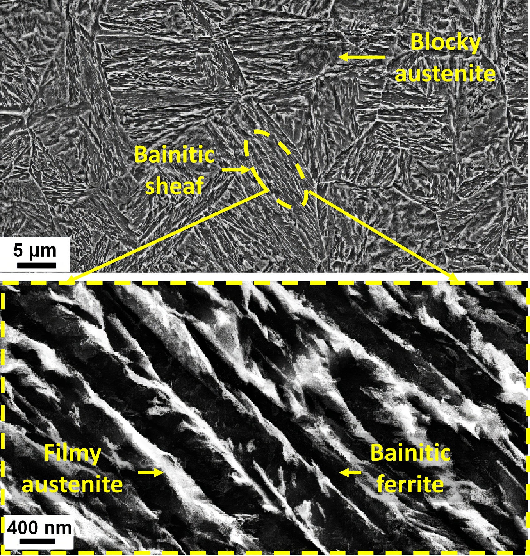
FESEM images of the BM at two different magnifications.
FSSW was carried out at a tool pin's plunge depth of 1.5 mm, a dwell time of 3 s, and a rotational speed ranging from 600 to 2000 rpm. The shoulder diameter of the WC-Co tool was 18 mm, while the diameter and height of the cylindrical pin were 4 mm and 1.5 mm, respectively.
According to standard metallographic procedures, the weld cross-sections were etched using a 2% Nital solution after grinding with abrasive paper and subsequent polishing. Macro and microstructural characterisations were carried out using a light optical microscope (LOM) and a TESCAN MIRA3 field-emission scanning electron microscope (FESEM). Electron backscatter diffraction (EBSD) analysis was performed by an FEI Versa 3D FESEM using a step size of 80 nm.
Vickers microhardness maps across the joint cross-sections were measured at 300 μm intervals using a load of 200 g and a dwell time of 15 s. Tensile-shear tests were performed using an Instron universal testing machine at a crosshead speed of 1 mm/min. The schematic of sample for tensile-shear test is shown in Figure S1 (Supplemental document, Section 1). According to Figure S2 (Supplemental document, Section 1), failure energy was calculated as the area under load–displacement curve up to maximum load. After central sectioning, the failed joints were examined using LOM to identify the fracture modes.
Results and discussion
Weld's geometrical features
A typical macrostructure of CFB steel friction stir spot weld is displayed in Figure 2(a). Referring to Figure 2(b–f) and regarding the hook definition provided in Supplemental document (Figure S4, Section 2.1), it can be seen that a strongly upward hook was formed at a rotational speed of 600 rpm, terminating near the top surface of the joint, as marked by blue arrow. Increasing the rotational speed caused the hook feature to gradually disappear in a way that a slightly upward one with the end far from the top surface of the upper sheet was obtained at 2000 rpm.

(a) Macrostructure of the weld fabricated at a rotational speed of 1500 rpm. Variations in the hook shape at rotational speeds of: (b) 600, (c) 800, (d) 1000, (e) 1500, and (f) 2000 rpm. The blue arrows designate the tips of the hooks. (g) Bonding width and effective thickness as a function of rotational speed, (h, i) magnified observations of the selected areas in (a).
The vertical interval from the hook tip to upper sheet's top surface, known as effective thickness, and the horizontal interval between the tip of the hook and keyhole periphery, called bonding width, are the most common weld geometrical attributes (Figure 2(f)). As shown in Figure 2(g), both the effective thickness and bonding width are significantly increased by about 820 and 350 µm, respectively, when increasing the rotational speed from 600 to 2000 rpm. The variations in hook configuration and geometrical characteristics are ascribed to various material flow behaviours under different rotational speeds. As suggested in Horie et al. and de Leon and Shin,19,20 during FSSW, consecutive material motions in rotational and vertical directions generate a helical vertical rotational material flow, which results in intermixing of materials between overlapped sheets and thus developing the bonding region. Under such circumstances, rotational speed is a key factor driving development of rotational material flow, 21 and upward material flow of lower sheet plays a decisive role in producing the hook feature. 22 From the above descriptions, it can be understood that enhancing the rotational speed from 600 to 2000 rpm provided a greater driving force for rotational material flow, 22 markedly contributing to stirring and disappearance of the hook feature, thereby increasing the effective thickness. This is in contrast with the data reported in literature, as provided in Supplemental document (Section 2.2). Additionally, the greater frictional heat generation associated with the higher rotational speeds promoted the extent of materials being intermixed 23 and thereby expanded the bonding width.
Microstructural characterisation
Based on the descriptions given in Supplemental document (Section 3), four distinct zones, including the SZ, thermo-mechanically affected zone (TMAZ), heat-affected zone (HAZ), and BM, were identified in the weld macrostructure, see Figure 2(h,i). The HAZ was further divided into three subzones, namely the fine-grain heat-affected zone (FGHAZ), inter-critical heat-affected zone (ICHAZ), and sub-critical heat-affected zone (SCHAZ). Figures 3 and 4 present FESEM micrographs of the various weld zones at rotational speeds of 600, 1000 and 2000 rpm, which are discussed below.

FESEM images of the various weld zones in the weld fabricated at 600 rpm and of the SZ in the weld fabricated at 1000 rpm.

FESEM images of the various weld zones in the weld fabricated at 2000 rpm.
Stir zone and thermo-mechanically affected zone
The microstructures of the SZ and TMAZ were mainly composed of lath martensite. The peak temperatures in the vicinity of keyhole (displayed in Figure S3 in Supplemental document (Section 1)) were 869, 873, 889, 931, and 963
Obviously, there was a microstructural refinement in the SZ and TMAZ relative to the BM, which became more pronounced in the SZ, attributable to the thermomechanical cycle associated with FSSW. During welding, both the SZ and TMAZ were subjected to intensive plastic deformation within the austenite regime, allowing DRX and subsequent austenite grain refinement to occur. Reconstructed prior austenite grain (PAG) boundaries maps in Figure S6 (Supplemental document (Section 3)) confirm grain refinement in the SZ. Given its shear transformation mechanism, martensite formation does not extend beyond the PAG boundaries. 25 Accordingly, the transformation of fine PAGs into fine martensite within both zones was unavoidable.
The recrystallised grain size is determined by the interplay between temperature and the extent of plastic deformation experienced during welding, such that lower peak temperature combined with more intense deformation tends to produce finer recrystallised grains. 26 Bearing in mind that the SZ was subjected to temperature and plastic deformation exceeding those of the TMAZ, and referring to Figures 3 and 4, it is clear that plastic deformation primarily governed the grain size in both zones at a given rotational speed, leading to finer recrystallised austenite grains and ultimately finer martensite in the SZ. Conversely, while both plastic deformation and peak temperature increased with enhancing the rotational speed,14,27 analysis of Figure 4 and Figure S6 reveals that elevated temperature was a dominant factor influencing the recrystallised austenite grain size at rotational speeds exceeding 600 rpm, making it prone to acquire larger PAGs and accordingly coarser martensite in the SZ and TMAZ. Furthermore, grain growth following DRX was another possible reason for coarser PAGs at higher rotational speeds coming from prolonged residence times at high temperatures within the austenite regime. 27 Image quality (IQ) maps for the SZs containing high-angle grain boundaries (HAGBs) with misorientation angles surpassing 15°, shown as green lines, provide additional evidence for generating coarser martensite structure at higher rotational speeds of 1000 and 2000 rpm (see Figure 5).
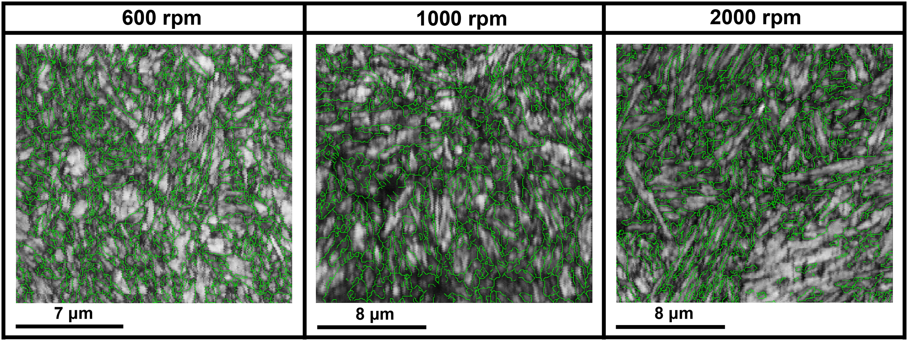
IQ EBSD maps for the SZs at various rotational speeds. High-angle grain boundaries are depicted with green lines.
Fine-grain heat-affected zone
The microstructure of the FGHAZ resembles that of the SZ and TMAZ, comprising fully fine martensite, as corroborated by X-ray diffraction (XRD) patterns provided in Figure S7 (Supplemental document (Section 3)). This observation suggests that peak temperature within the FGHAZ marginally exceeded the AC3 temperature, whereas it remained insufficient to facilitate growth of austenite grains, enabling the generation of fine PAGs and accordingly fine martensite upon rapid cooling. The absence of plastic deformation in the FGHAZ explains its relatively coarser microstructure relative to the SZ and TMAZ. On the other hand, as expected, higher peak temperature at higher rotational speed amplified the austenite grain growth, leading to a coarser martensitic microstructure.
Inter-critical heat-affected zone
The ICHAZ was characterised by the bainitic and martensitic microstructure, implying that this region was heated to the inter-critical temperature regime (AC1–AC3). As a consequence, the bainitic microstructure of the BM became partially austenitised and transformed into martensite during rapid cooling.
Sub-critical heat-affected zone
The SCHAZ demonstrated a tempered bainitic microstructure featuring decomposed austenite films and submicron precipitates embedded within bainitic ferrite platelets, which become more pronounced at higher rotational speed. This highlights that the SCHAZ was subjected to peak temperature below the AC1 and in turn tempering process, which became more prominent at higher heat input induced by higher rotational speed.
Microhardness
Figure 6 depicts the schematic of microhardness measurement locations, along with microhardness contour maps and average hardness values for the various weld zones at different rotational speeds. Evidently, remarkable hardening and softening were observed in the SZ and SCHAZ, respectively, the latter being more prominent at higher rotational speeds.
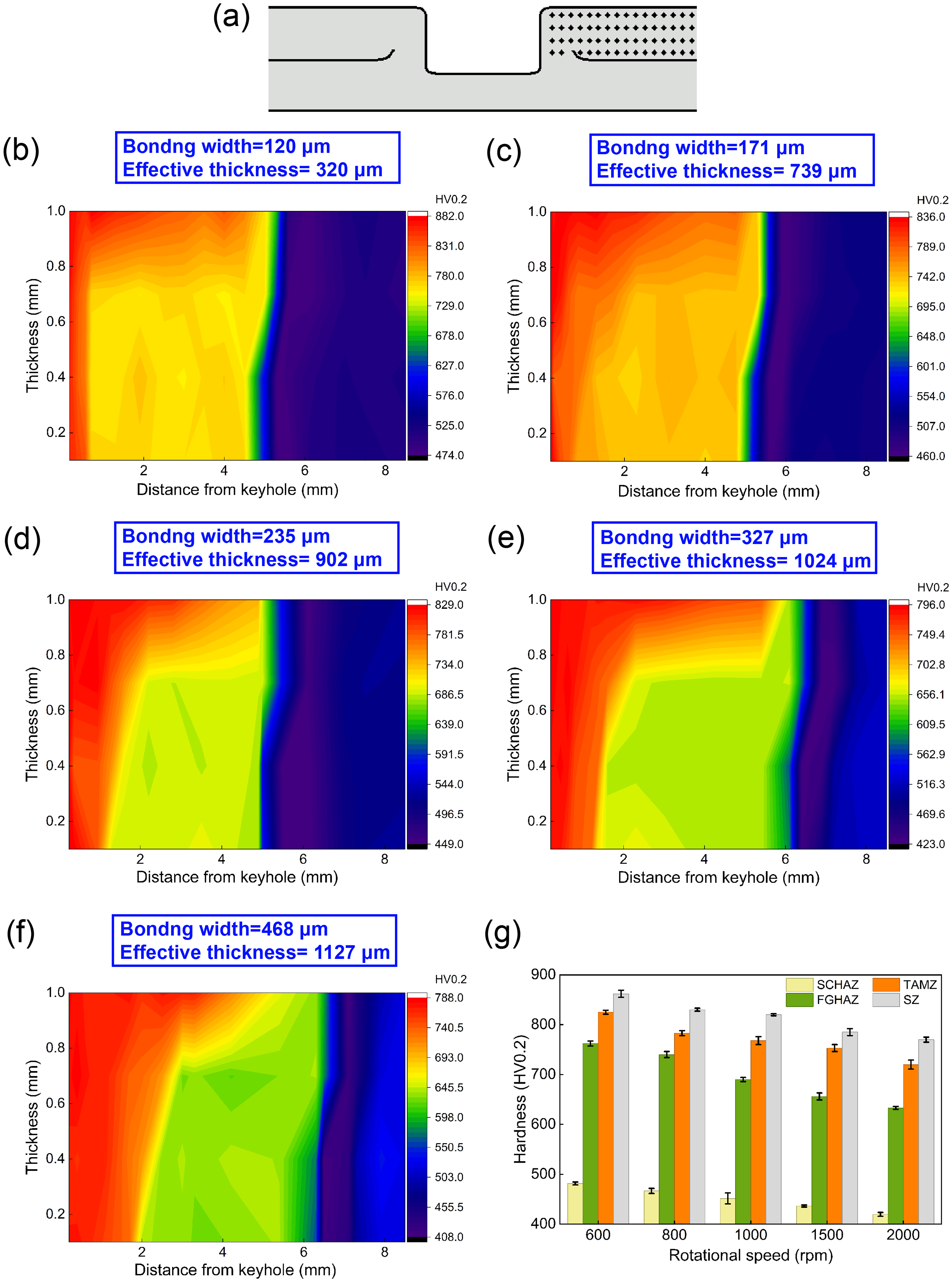
(a) Schematic illustration of the microhardness test conducted across the joint cross-section. Microhardness contour maps at rotational speeds of: (b) 600, (c) 800, (d) 1000, (e) 1500, and (f) 2000 rpm. (f) Average hardness data in various weld zones as a function of rotational speed.
During FSSW process, the recrystallised grains in both the SZ and TMAZ continuously underwent plastic deformation, introducing a large number of dislocations in both regions. 16 With this in mind and considering the more refined martensitic microstructure in the SZ, it is reasonable to expect the highest hardness in this region. Additionally, martensite coarsening toward the FGHAZ resulted in a gradual drop in hardness from the SZ toward FGHAZ. As the FGHAZ remained unaffected by mechanical cycle of welding, its lower dislocation density might also contribute to the reduced hardness. On the other hand, the softening detected in the SCHAZ resulted from tempered bainitic microstructure.
As observed in Figure 6(g), the development of coarser martensite in the SZ, TMAZ, and FGHAZ was associated with a decrease in hardness by about 95, 105, and 130 HV, respectively, when changing the rotational speed from 600 to 2000 rpm. Besides, more intense tempering at higher rotational speeds led to more prominent softening in the SCHAZ, accounting for a softening of 65 HV at 2000 rpm compared to 600 rpm.
Failure mode
The cross-sections of the lower sheets after failure under tensile-shear loading, together with schematics illustrating crack propagation paths at different rotational speeds, are shown in Figure 7. According to the definitions described in Supplemental document (Section 4.1), two failure modes were identified: interfacial failure and partial pullout failure. The joint manufactured at 600 rpm exhibited a partial pullout failure, while the joints were tended to fail through interfacial mode when employing higher rotational speeds.
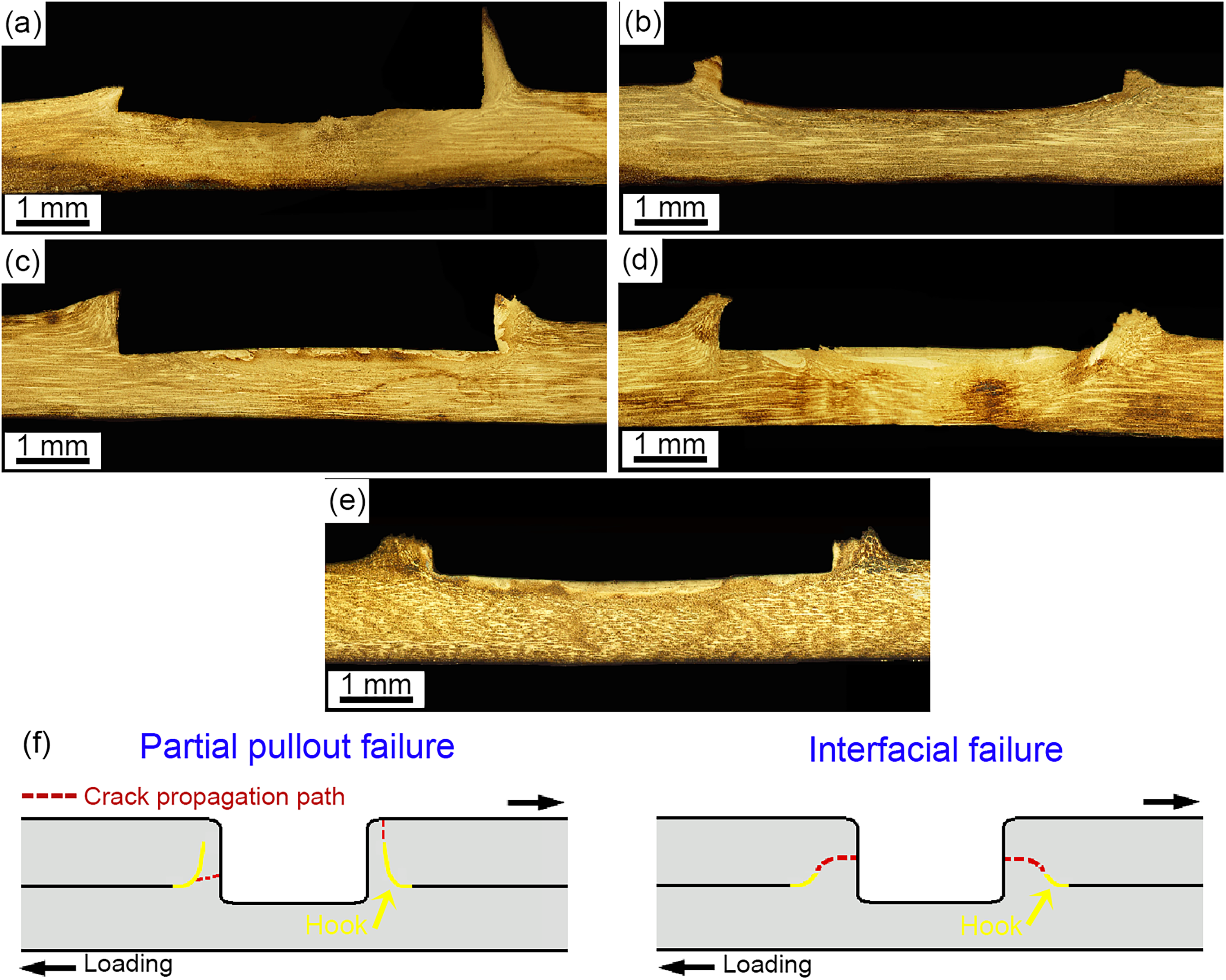
Cross-sections of the lower sheets after being failed under tensile-shear loading in welds fabricated at rotational speeds of: (a) 600, (b) 800, (c) 1000, (d) 1500, and (e) 2000 rpm. (f) Schematic demonstrations of crack propagation paths in different failure modes.
Based on existing literature,16,17 crack initiation likely occurred at the unbonded interface tip due to stress concentration. In the partial pullout fracture mode, the crack proceeded toward the keyhole on the left side while propagating along the hook in thickness direction toward the joint's top surface on right side (Figure 7(a,f)). On the other hand, in the interfacial fracture mode, the crack grew along the hook followed by progressing across the bonding region toward the keyhole (Figure 7(b–f)). The hook provides a preferential path for crack propagation due to its weak bonding induced by oxides,14–16 explaining why the crack initially passed along the hook under all conditions, consistent with the hook shapes depicted in Figure 2(b–f).
Based on the literature included in Supplemental document (Section 4.2), failure mode is believed to be principally dictated by the weld's geometrical characteristics. As evidenced by results given in Figure 2(g), Figure 7 and Table S2 (Supplemental document (Section 4.2)), a smaller bonding width compared with effective thickness did not promote interfacial failure. On the other hand, there was no clear correlation between the failure mode and proportion of the bonding size to effective top sheet thickness, collectively, ruling out the possible effect of bonding width on the failure mode. Consequently, it can be suggested that the effective thickness in conjunction with hook shape played a crucial role in determining the failure mode. In fact, at a rotational speed of 600 rpm, the reduced effective thickness induced by upward displacement of the hook made failure easy to occur along thickness direction, giving rise to partial pullout fracture. By contrast, at higher rotational speeds, an enlarged effective thickness and slightly upward hook inhibited cracking along direction of thickness, providing the interfacial failure.
Mechanical properties
The variations in failure energy of the welds with rotational speed are presented in Figure 8. As can be seen, the failure energy increased by 2.5 J when the rotational speed increased from 600 to 1000 rpm, while it experienced a drop of 4.4 J as the rotational speed continued to increase to 2000 rpm.
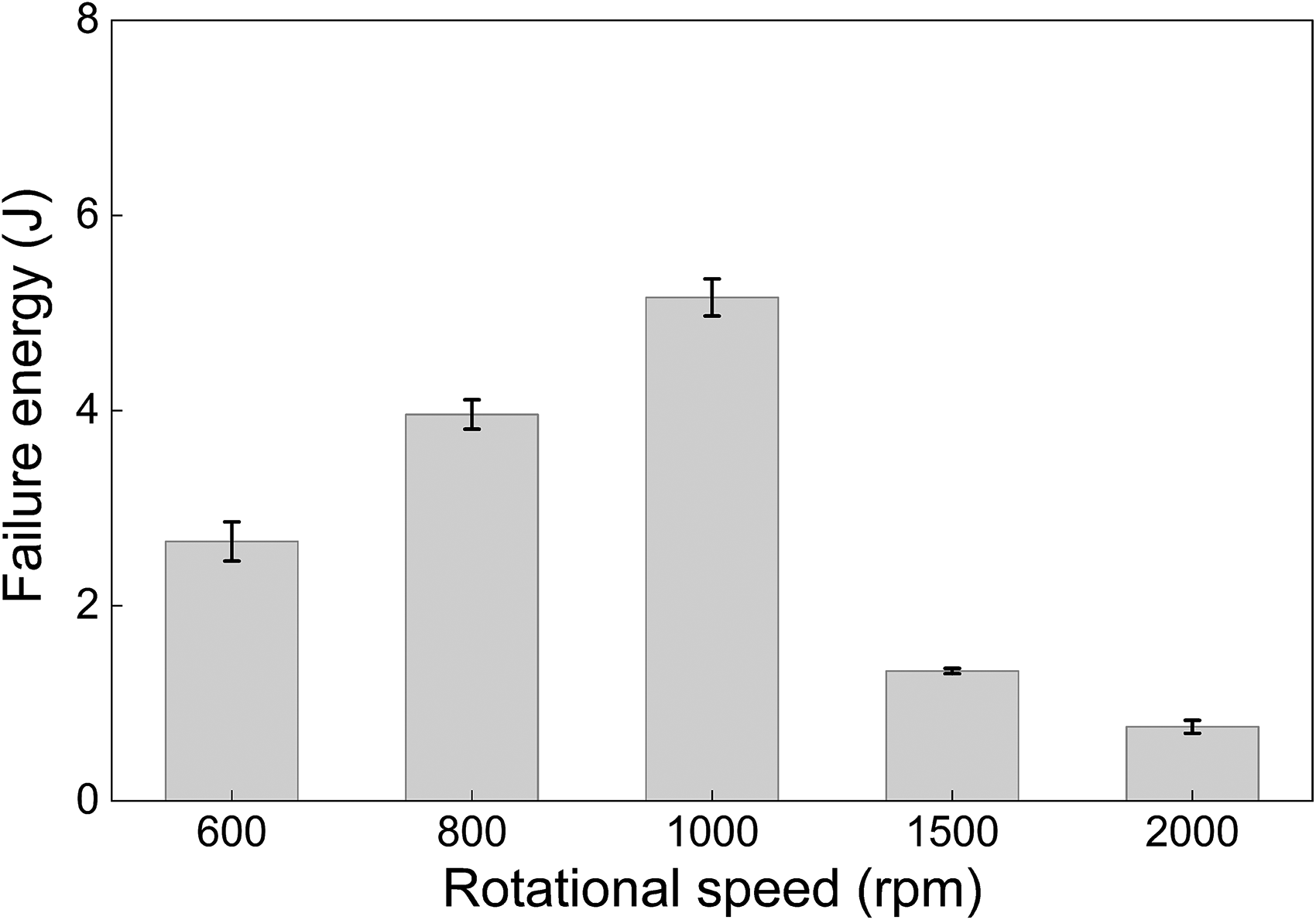
Effect of rotational speed on failure energy under tensile-shear loading.
The failure energy of FSSW joints under tensile-shear loading is significantly governed by bonding width as well as fracture toughness of bonding region, i.e., the SZ.23,28 It is important to note that the weld's failure behaviour was independent of the SCHAZ softening, as evidenced in Supplemental document (Section 5.1). Generally, the formation of more HAGBs associated with martensite substructural refinement enables improvement of toughness in martensitic steels. 29 Additionally, retained austenite is known to be capable of improving the toughness via trapping/deflecting the propagating crack, strain-induced martensite transformation (i.e., TRIP effect), and blunting the crack tip. 30 Given the low austenite content of the SZ (%1–3), it seems that this phase made a negligible contribution to the weld's failure energy, highlighting the prevailing role of martensite in governing the fracture toughness of mainly martensitic microstructure of the SZ. Taken together, it can be inferred that despite a narrow bonding width at 600 rpm, the finer martensite structure within the SZ made crack propagation difficult to proceed, resulting in moderate failure energy. Moreover, extending the bonding width by increasing the rotational speed to 1000 rpm could take its beneficial role in improving the energy absorption capability, as the crack requires more energy to traverse the abundance of relatively coarse martensite structure. The obtained maximum failure energy at 1000 rpm agrees well with the highest failure load at the same rotational speed being reported in our previous work. 12 However, the larger bonding width at rotational speeds exceeding 1000 rpm did not improve the mechanical response, because development of coarser martensite within the SZ facilitated crack propagation, as corroborated by the fracture surfaces provided in Supplemental document (Figure S9, Section 5.2).
It is noteworthy that no clear correlation between the fracture mode and failure energy was identified. Evidently, the partial pullout failure did not guarantee the highest energy absorption capability, as well. Similarly, Sun et al. 31 indicated that the welds possessing the highest failure load were accompanied by an interfacial mode.
The present work emphasises that optimal failure energy demands a balance between bonding width and microstructural refinement. Furthermore, FSSW parameter selection shouldn’t be based solely on failure load, but rather on controlling weld geometry to ensure energy-absorbing failure modes, which is critical for automotive structural applications. The proposed microstructure–geometry–failure relationship is expected to be transferable to other similar/dissimilar steel joints produced by FSSW, particularly for AHSSs.
Conclusion
Given the growing application potential of CFB steels in the automotive body structures, investigating the factors affecting the fracture behaviour of their spot welds is essential to control the joint mechanical performance. Assessment of microstructure and failure features of ultrafine CFB steel FSSW joints led to the following key conclusions:
Elevated peak temperatures at higher rotational speeds promote the formation of coarser martensitic structures in the SZ, TMAZ, and FGHAZ, as well as more pronounced tempering in the SCHAZ. An enlarged effective thickness ( A sufficiently large bonding region containing fine martensite at 1000 rpm effectively suppresses crack propagation, resulting in the highest failure energy.
Supplemental Material
sj-docx-1-stw-10.1177_13621718261432367 - Supplemental material for Failure of friction stir spot welds in carbide-free bainitic steel: effects of physical and metallurgical weld attributes
Supplemental material, sj-docx-1-stw-10.1177_13621718261432367 for Failure of friction stir spot welds in carbide-free bainitic steel: effects of physical and metallurgical weld attributes by Maryam Kabirmohammadi, Sasan Yazdani and Majid Pouranvari in Science and Technology of Welding and Joining
Footnotes
Ethical approval and informed consent statements
This article does not contain any studies with human or animal participants.
Author contributions
Maryam Kabirmohammadi: writing ‒ original draft, conceptualization, methodology, investigation, resources. Sasan Yazdani: supervision, writing ‒ review and editing. Majid Pouranvari: supervision, writing ‒ review and editing.
Funding
The authors received no financial support for the research, authorship, and/or publication of this article.
Declaration of conflicting interests
The authors declared no potential conflicts of interest with respect to the research, authorship, and/or publication of this article.
Data availability
The data will be made available upon request.
Supplemental material
Supplemental material for this article is available online.
References
Supplementary Material
Please find the following supplemental material available below.
For Open Access articles published under a Creative Commons License, all supplemental material carries the same license as the article it is associated with.
For non-Open Access articles published, all supplemental material carries a non-exclusive license, and permission requests for re-use of supplemental material or any part of supplemental material shall be sent directly to the copyright owner as specified in the copyright notice associated with the article.