
Abstract
To address weldability challenges and achieve excellent tensile performance of low-density austenitic steel in friction stir welding (FSW), two low heat input parameters were used to join Fe–30Mn–9Al–0.85C steel. The results indicate that low heat input suppresses the dissolution of κ-carbides in the stir zone, while promoting the growth of grains and carbides and increasing annealing twin boundaries (ATBs) in the heat-affected zone (HAZ). The welded joints exhibited a joint efficiency of 103%. This study uncovers a mechanism – during tensile deformation in the HAZ, ATBs transformed into high-angle grain boundaries, leading to grain refinement and giving rise to the dynamic Hall–Petch effect – that enables a strategy for achieving the excellent tensile performance of FSW joints in low-density austenitic steel.
Keywords
Introduction
In recent years, the Fe–Mn–Al–C steels have met the demands of the automotive industry for low-density vehicles and improved fuel efficiency, while also providing excellent corrosion resistance for hulls and offshore structures in marine environments, thereby contributing to the development of a green economy.1–3 Based on alloy composition, these steels can be classified into four main categories: ferritic, ferrite-based duplex, austenite-based duplex and austenitic steels. 4 Among them, high-Mn austenitic low-density steel exhibits mechanical properties comparable to those of high-Mn twinning-induced plasticity (TWIP) steels. 2 The low-density characteristics of high-Mn austenitic low-density steels are due to the addition of Al element, the density of steel decreases by approximately 1.3% per 1 wt.% of Al added.3,5 And the high Al (>6.5 wt.% 6 ) content in low-density steels promotes the precipitation of κ-carbides, which possess a crystal structure similar to perovskite – specifically, an ordered L1₂ structure – and act as the primary strengthening phase.7,8 Additionally, the stacking fault energy of high-Mn low-density austenitic steels increases with higher Al content, shifting the dominant deformation mechanism from TWIP to shear band–induced plasticity, 9 microband-induced plasticity10,11 and dynamic slip band refinement. 12
In the past decade, many researchers have attempted to weld high-Al low-density austenitic steels using various fusion welding processes, such as gas metal arc welding, gas tungsten arc welding, electron beam welding and laser beam welding.13–16 However, these welding methods have a high risk of metallurgical defects. For example, hot cracking defects were identified in the weld metal due to the formation of liquid film containing high Al and Mn elements.14,15 Furthermore, although these risks can be avoided by adjusting welding parameters, the excellent mechanical properties of the joint are hardly achieved.17–19
Friction stir welding (FSW) is a solid-state joining technique that can effectively avoid common fusion-related defects.20,21 Friction stir welding has been extensively studied in conventional steels, producing defect-free weld microstructures and excellent mechanical properties.22–24 Therefore, several studies have confirmed the feasibility to join low-density steels by FSW.25–28 It was first found that the mechanical properties of the stir zone (SZ) decreased due to the redissolution of κ-carbide due to high heat input during friction stir processing (FSP) for high-Al low-density austenitic steel. 26 The κ-carbide redissolution was resolved through post-weld heat treatment. Then Chen et al.27,28 achieved the excellent mechanical properties of the SZ of high-Al low-density ferrite steels by employing low heat input parameters. The low heat input prevented the redissolution of the κ-carbide and promoted the precipitation of fine cementite in the SZ. Nevertheless, the influence of different zones contained in the tensile gauge length on the tensile properties of the FSW joint remains unclear. For example, the heat-affected zone (HAZ) usually plays an important role in determining the performance as a softened zone in both fusion welding and FSW joints. The formation of this soft zone is generally attributed to several microstructural factors, including the dissolution of strengthening secondary phases, grain coarsening or phase transformations.20,29,30 Previous studies have demonstrated that the dynamic Hall–Petch effect can effectively enhance material performance.31–33 The performance of HAZ can be enhanced through the dynamic Hall–Petch effect, thereby improving the overall mechanical properties of the welded joint. This provides important insights for regulating the mechanical properties of friction stir-welded joints in high-Al low-density austenitic steels. These results confirm that FSW is a viable technique for joining low-density steels. However, whether high-Al low-density austenitic steel can be successfully welded by FSW remains unclear.
Therefore, to investigate the weldability of FSW in high-Al low-density austenitic steel and the relationship between its microstructure and mechanical properties, the present study employed two low heat input sets of FSW parameters to join Fe–30Mn–9Al–0.85C steel. The microstructures of both the SZ and HAZ were systematically investigated, and the evolution of the HAZ microstructure and its influence on mechanical properties during tensile deformation were analyzed. The aim was to explore new mechanisms and approaches to enhance the performance of FSW joints in high-Al low-density austenitic steels.
Experimental procedures
Fe–30Mn–9Al–0.85C low-density austenitic steel was melted using a vacuum induction furnace. Its actual chemical composition (wt.%) was: 29.23 Mn, 9.7 Al, 0.84 C, 0.17 Si, 0.087 Nb, 0.091 V and balance Fe. The ingot was homogenised at 1423–1453 K, followed by forging, hot rolling and water quenching. Friction stir welding was performed using an FSW-3LM-2010 research-grade system. The stir tool, made of a tungsten–rhenium alloy, featured a concave shoulder with a diameter of 18 mm and a pin 6 mm in length. Two rotational speeds of 200 and 300 rpm were employed, combined with a constant travel speed of 80 mm/min, and the samples were designated as 200–80 and 300–80. The material consisted of two 6.2-mm steel plates joined by a butt weld. The stir tool was tilted at an angle of 2°, and argon gas shielding was used to prevent oxidisation during FSW. Internal temperatures during welding were measured by embedding type k thermocouples, by boring 2 mm diameter and 2mm depth holes by electric discharge machining from the edge of the plate. Figure 1 shows the position of the thermocouples in BM. The thermocouple position started from the outermost side of the forward shaft shoulder and gradually moved backward from the shaft shoulder in 5 mm increments. Each measurement point was referred to as AS-0, AS-0.5, AS-1 and AS-1.5, respectively.
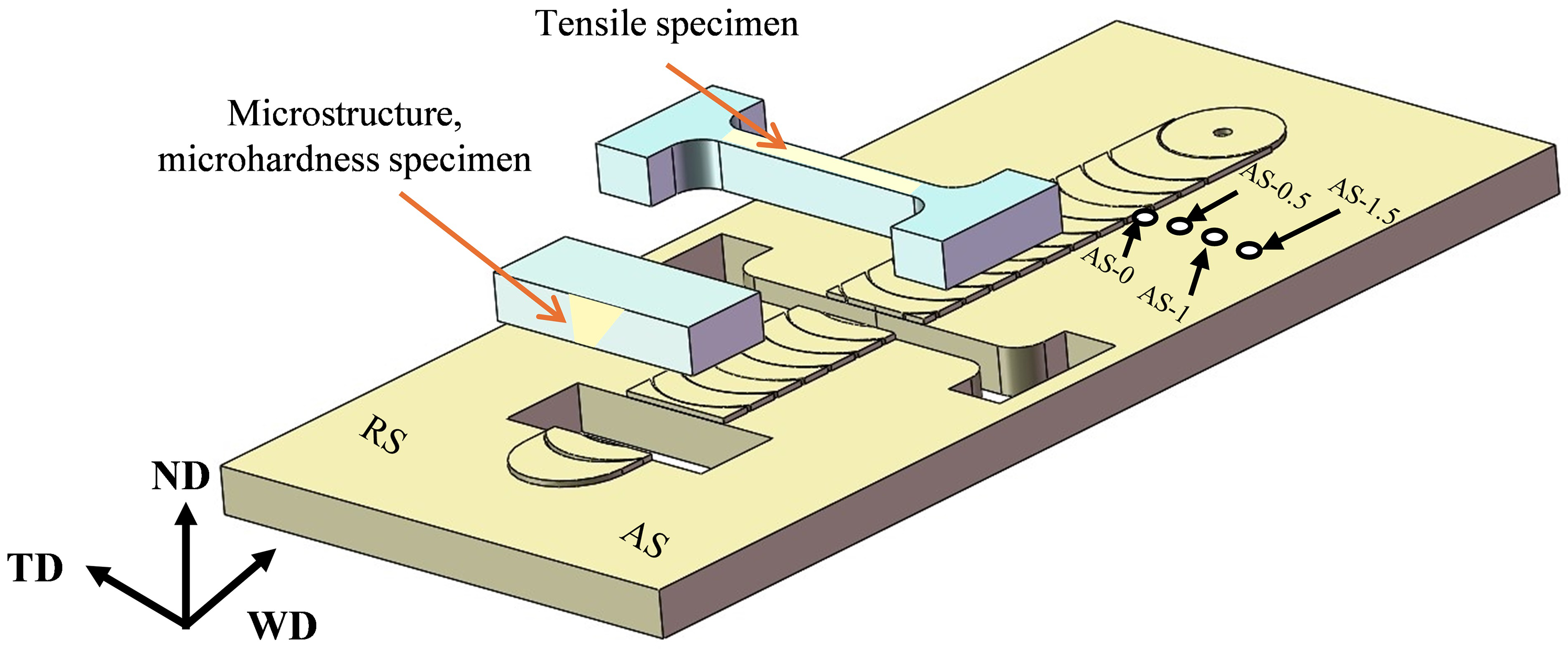
A schematic illustration of friction stir welding, sampling locations and the position of the thermocouples. RS: retreating side; AS: advancing side; WD: welding direction.
The samples for microstructural observation and tensile testing were extracted from the positions, indicated in Figure 1. The microstructure of the SZ was examined using an optical microscope (OM, Carl Zeiss Jena, Germany), scanning electron microscopy (Hitachi SU5000 Field Emission Gun) with an electron backscatter diffraction (EBSD) detector and transmission electron microscopy (TEM, FEI Talos F200x). Optical microscope samples were etched in a solution of 10% nitrate alcohol. Electron backscatter diffraction samples were finely polished and subsequently subjected to ion bombardment. Transmission electron microscopy samples were cut and ground to a thickness of approximately 50 μm and a diameter of 3 mm, followed by ion-beam milling at 3 kV with an incidence angle of 5°.
The hardness distribution perpendicular to the welding direction was measured using a fully automatic microhardness tester (FM-ARS-9000). Tensile samples had a width of 3 mm, a thickness of 2 mm and a gauge length of 45 mm. Tensile tests were performed on a SUNS UTM4304-GD electronic universal testing machine at a nominal strain rate of 1 × 10⁻³ s−1. To ensure reliability, three samples were tested under each set of conditions.
Results
Microstructure of the FSW joints
Figure 2(a) and (b) shows the macroscopic morphologies of the FSW joints under the two parameter sets. The joint exhibited a ‘basin-shaped’ morphology without obvious defects such as holes and cracks. The banded structures observed at the root of the SZs were composed of tungsten–rhenium (W-Re) alloy, which resulted from the intense thermomechanical action of the stir tool. 26 This is a common phenomenon in FSW and is not expected to impair the mechanical properties. 34
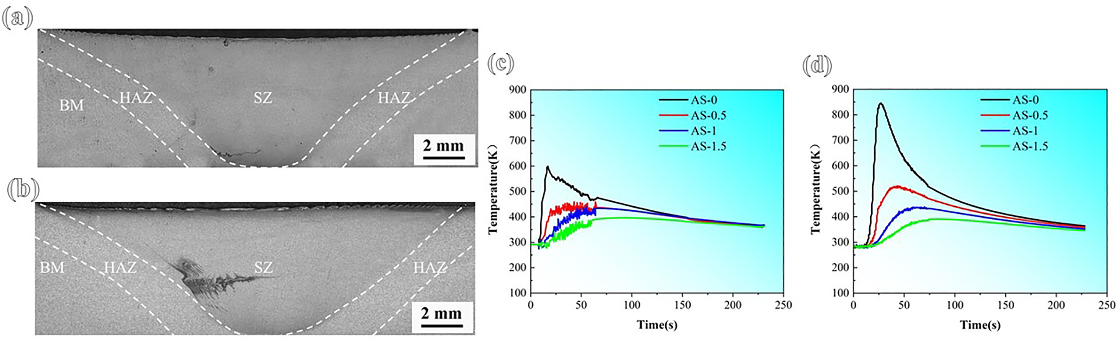
Macrostructures of the friction stir welding (FSW) joints under two parameters and temperature measurement data: (a) and (c) 200–80, (b) and (d) 300–80.
Figure 3 shows the EBSD analysis of the BM, SZ and HAZ microstructures. The inverse pole figure (IPF) map (Figure 3(a)) shows that the BM has an average grain size (AGS) of 19.3 μm. According to the grain orientation spread (GOS) map (Figure 3(b)), the fraction of recrystallised grains in the BM is approximately 70.2%. As shown in Figure 3(c), the BM contains a relatively high fraction (37.8%) of <111> 60° annealing twin boundaries (ATBs), which accounts for roughly one-third of the total high-angle grain boundaries (HAGBs). The microstructure was single-phase austenitic.

Electron backscatter diffraction (EBSD) analysis of the BM and the stir zone (SZ) and heat-affected zone (HAZ) under the two welding parameters (200–80 and 300–80): (a–a4) inverse pole figure (IPF) map, (b–b4) grain orientation spread (GOS) map, (c–c4) phase map with <111>60° annealing twin boundaries (ATBs) highlighted in green.
The AGSs in 200–80 SZ and 300–80 SZ were 10.7 and 16.8 μm, respectively (Figure 3a 1 and a 2 ), indicating refinement compared with the BM (19.3 μm). The GOS maps revealed that the fraction of recrystallised grains decreased from 70.2% in BM to 65.5% and 63.3% in SZ. The proportion of <111>60° ATBs remains relatively high at 26.8% and 28.7%, respectively (Figure 3c 1 and c 2 ). Furthermore, the SZ microstructures retained a single-phase austenitic structure during FSW.
The AGSs in HAZ were 39.6 μm and 45.1 μm under the two conditions, indicating grain coarsening relative to the BM. Figure 3b 3 and b 4 show that the recrystallisation fraction in both HAZs exceeded 80%, higher than that of the BM and SZ. Moreover, the proportion of <111> 60° ATBs increased significantly compared with the other zones, reaching 47.8% and 59.4%, respectively (Figure 3c 3 and c 4 ). A detailed comparison of the microstructural characteristics of the BM, SZ and HAZ is presented in Table 1.

Transmission electron microscopy (TEM) observations of the BM, stir zone (SZ) and heat-affected zone (HAZ) under the two welding parameters (200–80 and 300–80): (a–a4) BF images, (b–b4) dark-field (DF) image, (c–c4) selected area electron diffraction (SAED) pattern.
Microstructural characteristics of the BM, SZ and HAZ regions, including AGS, GOS (<2°) and proportion of <111>60°ATBs.
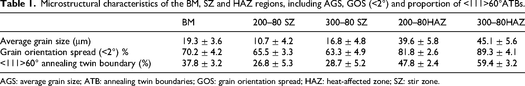
AGS: average grain size; ATB: annealing twin boundaries; GOS: grain orientation spread; HAZ: heat-affected zone; SZ: stir zone.
Further TEM observations of the BM, SZ and HAZ microstructures are shown in Figure 4. Fine, spherical particles were observed in the BF and dark-field (DF) images (Figure 4(a) and (b)). Selected area electron diffraction (SAED) analysis (Figure 4(c)) confirmed the presence of nanoscale κ-carbide precipitates, with an average diameter of 5 ± 2 nm (measured using the linear intercept method).
The TEM micrographs of the 200–80 SZ and 300–80 SZ microstructures are shown in Figure 4. The BF and DF images (Figure 4a1–b1 and a2–b2) revealed finely dispersed secondary phase particles in both SZs. The corresponding SAED patterns (Figure 4c 1 and 4c 2 ) confirmed that these particles were κ-carbides, with an average size of 5 ± 2 nm.
Unlike previous FSP studies, 26 the κ-carbides were successfully retained in the SZ due to the reduced heat input in the present study. To determine the peak temperature under low heat input welding parameters, a K-type thermocouple was used to measure the welding temperature. As shown in Figure 2(d), a peak temperature of 853 K was recorded at point AS-0 of 300–80 parameter. During FSW/FSP of steel, experiments and models consistently indicated that the peak temperature zone was located in the high-shear layer near the tool shoulder/pin.35,36 Thus, 853 K could be considered close to the temperature of the SZ. However, readings from embedded thermocouples, which struggled to precisely follow the actual interface/SZ, were typically lowered by thermal dissipation and dynamic response lag. 37 Consequently, calibration using data closer to the interface was necessary. David et al. 38 successfully achieved direct temperature measurement at the tool–workpiece interface, confirming that interface temperatures were approximately 20–30% higher than indirect measurements. Based on this, the actual peak temperature was estimated to be between 923 K and 1023 K under the 300–80 parameter. For the 200–80 parameter, the peak temperature was expected to be lower than that for the 300–80 parameter. The thermal stability of κ-carbides was enhanced by higher Mn, Al and C contents. Even after ageing at 1323 K for 30 min in Fe–30Mn–8Al–0.9C steel, these carbides remained present. 39 This indicated that κ-carbides in the SZ might not completely redissolve during FSW by using low heat input parameters. This view was also demonstrated by Chen et al.27,28
Figure 4a3–c3 and a4–c4 shows the TEM micrographs of the HAZ microstructure. The BF and DF images (Figure 4a3–b3 and a4–b4) also revealed finely dispersed secondary phase particles in both HAZs. The corresponding SAED patterns confirmed their identity as κ-carbides (Figure 4c 3 and c 4 ). The κ-carbides in the HAZ coarsened under both FSW conditions, with their size increasing at higher rotational speed. The average sizes of κ-carbides in the 200–80 HAZ and 300–80 HAZ were 7 ± 2 nm and 8 ± 3 nm, respectively, with a maximum size of 11 nm. Notably, no intergranular κ-carbides were observed in the HAZ.
Mechanical properties of FSW joints
Figure 5 shows the Vickers hardness distribution measured along the cross-section of the two FSW joints. The hardness of the SZs was higher than that of the BM, with the hardness of the SZs reaching a maximum value of approximately 310 HV. The HAZ exhibited the lowest hardness in the welded joints.
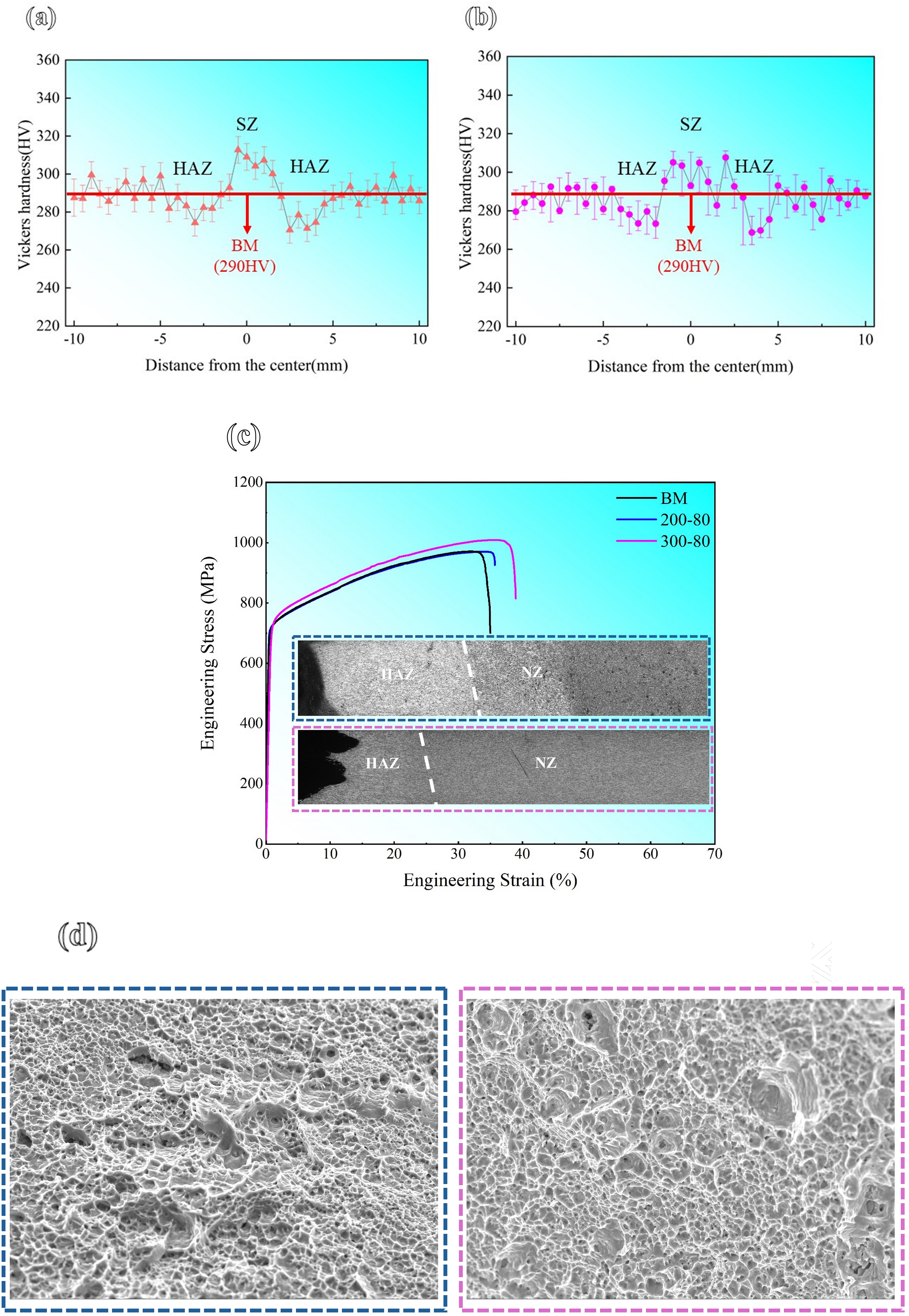
Mechanical properties and fracture characterisation of the welded joints: (a, b) Vickers hardness distributions; (c) engineering stress–strain curves with optical microscope (OM) images showing fracture locations; (d) (e) tensile fracture surface of the 200–80 and 300–80.
Figure 5(c) shows the mechanical properties of the BM and the FSW joints under the two welding parameters. The YS, UTS and UE for the BM and under parameters 200–80 and 300–80 were 715 ± 13, 705 ± 17 and 727 ± 9 MPa; 970 ± 8, 971 ± 8 and 1008 ± 20 MPa; and 32 ± 2%, 32 ± 5% and 33 ± 3%, respectively. The results indicated that the FSW joints had YS comparable to that of the BM. More importantly, the UTS and UE of the joints were higher than those of the BM. These two low heat input parameters avoided the mechanical property degradation typical of fusion welding and enhanced the properties of the FSW joints in this high-Al low-density austenitic steel. As shown in Figure 5(c), fractures in both FSW joints occurred in the HAZ, which corresponded to the region of lower hardness. The images in both Figure 5(d) and (e) exhibit a dense dimple morphology, suggesting a ductile fracture mode. This is consistent with the high elongation and superior joint efficiency observed.
Discussions
In the present study, although the HAZ acted as a soft zone, the mechanical properties of the joints were not compromised. The FSW joint achieved an efficiency of 103% and maintained excellent strength and ductility. We therefore proposed that the HAZ microstructure underwent a beneficial evolution during tensile deformation that positively influenced mechanical performance. This warranted an in-depth investigation into the microstructural evolution of the HAZ during tensile deformation. To investigate this, an in-situ EBSD analysis was conducted to systematically characterise the microstructural evolution in the HAZ under different strain levels.
Figure 6 shows the IPF and KAM maps of the two HAZs at different strain levels. At the initial strain stage (ε = 0%), the AGS values of the two HAZs were 44.8 and 47.7 μm, respectively, while the HAGB densities were 0.1342 and 0.1462 μm⁻1. With increasing strain, the density of HAGBs increased continuously. The AGS increased at a strain of 5% but subsequently decreased. Notably, the AGS in the 300–80 HAZ decreased to a value lower than its initial state at ε = 0%. Grain refinement corresponded to an increase in the density of HAGBs. This phenomenon of grain refinement occurring during deformation is called the dynamic Hall–Petch effect. In contrast to the conventional static Hall–Petch effect, which emphasises the influence of initial grain size or interface spacing on yield strength, the dynamic Hall–Petch effect focuses on the continuous introduction of new interfaces during plastic deformation to obstruct dislocation motion.32,40 This leads to sustained work hardening throughout the deformation process. This dynamic Hall–Petch effect is a key mechanism responsible for the excellent mechanical properties of the welded joint. Recent research further showed that this type of dynamic Hall–Petch effect enhances mechanical properties.41,42

Electron backscatter diffraction (EBSD) analysis of the heat-affected zones (HAZs) at different strain levels, with corresponding average grain size (AGS) and high-angle grain boundary (HAGB) density: (a–d, a1–d1) EBSD maps and (i) AGS/HAGB density for the 200–80 HAZ; (e–h, e1–h1) EBSD maps and (j) AGS/HAGB density for the 300–80 HAZ.
To understand the reason for this dynamic Hall–Petch effect, characteristic grains were analyzed. The results revealed that the effect was caused by the transformation of ATBs into HAGBs. The regions marked by white squares in Figure 6(a) are magnified in Figure 7. Characteristic grains within these regions are highlighted with white lines for analysis. At ε = 0%, the grain boundaries of these characteristic grains primarily consisted of highly coherent <111> 60° ATBs, with very low dislocation density within the grains (Figure 7a1–a3). When the tensile strain reached 5%, dislocation density within the characteristic grains increased markedly, and the ATBs began to transform into HAGBs (Figure 7b1–b3). This phenomenon occurred because dislocations accumulated near ATBs and dissociated into mobile Shockley partial dislocations and immobile Frank partial dislocations (α/2<110>→α/6<11–2>+α/3<111>). The motion of Shockley partial dislocations along ATBs leads to their immediate transformation into conventional HAGBs. 43 At ε = 10%, further dislocation pile-up around ATBs promoted their transformation into HAGBs (Figure 7c1–c3). By ε = 15%, most ATBs had transformed into HAGBs (Figure 7d1–d3), resulting in further grain refinement. Notably, the crystallographic orientations of the characteristic grains and their surrounding grains remained unchanged throughout this process. This explains why the increasing strain led to a higher density of HAGBs and grain refinement, which induced the dynamic Hall–Petch effect. Unlike the dynamic Hall–Petch effect induced by deformation twinning during tensile deformation,44,45 this effect is achieved through the transformation of ATBs. Thus, the dynamic Hall–Petch effect observed in the softened HAZ enables it to maintain work hardening during tensile deformation, thereby contributing to the excellent performance of the welded joint.

Magnified view of the white square region in the 200–80 heat-affected zone (HAZ) map: (a1–d1) inverse pole figure (IPF) images, (a2–d2) grain boundary images, (a3–d3) KAM images.
Furthermore, κ-carbides significantly influenced YS. Previous studies have demonstrated that finely dispersed κ-carbides could effectively enhance the YS of low-density steels.46,47 This strengthening effect was further increased as κ-carbides developed from nanoscale precipitates into rectangular domains.48,49 In this study, the κ-carbides in the HAZ were significantly larger than those in the BM. Their presence provided additional strengthening that offsets the softening effect of grain coarsening in the HAZ. Then, grain refinement and κ-carbides were achieved in the SZ due to the low heat input, resulting in the YS of the welded joint like that of the BM. Finally, the dynamic Hall–Petch effect occurring during tensile deformation enhanced the UTS of the welded joints.
Conclusion
Defect-free FSW joints in Fe–30Mn–9Al–0.85C low-density austenitic steel were successfully produced using low heat input parameters. The SZ exhibited grain refinement and retention of κ-carbides, and the HAZ showed coarsening of both grains and κ-carbides. The HAZ contributed to overall joint performance through a distinct deformation mechanism.
The proportion of ATBs in the HAZ increased from 37.8% in the BM to 47.8% and 59.4% under the two FSW parameters, respectively. The FSW joints exhibited YS comparable to that of the BM, while the UTS and elongation were improved, resulting in joint efficiency exceeding 100%. An enhancement of mechanical properties was successfully achieved.
In the softened HAZ, tensile deformation induced dislocation–ATB interactions that transformed <111>60° ATBs into HAGBs
This article demonstrates the potential of low heat input FSW for industrial lightweight applications. The combination of strength and ductility highlights the promise of low heat input FSW in industrial settings, particularly in the automotive and aerospace sectors, which have substantial demand for lightweight, high-strength steels. Regarding the observed dynamic Hall–Petch effect, future research should focus on in situ characterisation, multi-scale modelling and fatigue behaviour to further validate this mechanism and support industrial implementation.
Footnotes
Author contributions
Hongyan Lv contributed to conceptualisation, methodology, formal analysis, investigation, data curation, writing – original draft and visualisation. Ruidong Fu contributed to conceptualisation, resources, data curation, writing – review & editing and supervision. Yijun Li contributed to conceptualisation, formal analysis and writing – review & editing. Chunyu Wang contributed to methodology. Heshuai Dong contributed to software. Junpeng Li and Bingjie Ji contributed to software.
Funding
The authors disclosed receipt of the following financial support for the research, authorship and/or publication of this article: This study was supported by the Science & Technology Program of Hebei (246Z1003G).
Declaration of conflicting interests
The authors declared no potential conflicts of interest with respect to the research, authorship and/or publication of this article.
Data availability statement
The datasets generated during and/or analyzed during the current study are not publicly available, as the data also form part of ongoing study.