
Abstract
This study investigated the microstructure and mechanical properties of dissimilar vacuum electron beam welded joints between TU1 oxygen-free copper and 316L stainless steel. Sound, defect-free welds with a characteristic nail-head profile were achieved. The fusion zone exhibited a complex interpenetrating microstructure comprising Fe-rich and Cu-rich zones with dispersed particulates. EBSD analysis revealed a significant grain size gradient, with fine equiaxed grains at the fusion line and coarse columnar grains growing epitaxially into the fusion zone. Mechanical testing demonstrated that joint failure occurred in the weaker heat-affected zone rather than the weld joint, with a yield strength of ∼123.5 MPa and elongation of ∼6.8%. These results demonstrated that EBW was an effective technique for producing reliable copper/stainless steel dissimilar joints.
Introduction
The joining of dissimilar metals had attracted considerable attention due to the increasing demand for components with tailored properties that cannot be achieved by a single material.1,2 Among various dissimilar combinations, copper to stainless steel joints were of particular interest in nuclear fusion reactors, particle accelerators and heat exchangers, where the excellent electrical and thermal conductivity of copper was combined with the high strength and corrosion resistance of stainless steel.3,4 However, reliable joining of copper and stainless steel presented significant challenges due to substantial differences in their physical and metallurgical properties, including melting points (∼1083 °C for copper vs. ∼1400 °C for steel), thermal conductivity (∼400 W/m·K for copper vs. ∼15 W/m·K for steel) and thermal expansion coefficients (∼16.6 × 10⁻⁶/K for copper vs. ∼17.5 × 10⁻⁶/K for steel). These disparities often led to high residual stresses, solidification cracks and incomplete fusion.5,6
To address these challenges, various solid-state and fusion welding techniques had been investigated. Diffusion bonding had been widely studied for copper-stainless steel joining due to its ability to minimise detrimental reactions.7,8 Laser welding has emerged as a promising alternative owing to its high energy density and precise heat control.9,10 Electron beam welding (EBW), characterised by high energy density, deep penetration and a vacuum environment, offered distinct advantages for dissimilar metal joining, particularly for materials with high thermal conductivity such as copper.11–13 Enzinger et al. 14 addressed the challenges of EBWed thick copper components and demonstrated that copper–tin alloy filler metal could stabilise root formation by increasing the solidification temperature range. Elmer and Gibbs 15 systematically characterised astigmatic electron beam propagation and its influence on weld pool shape, revealing that beam ellipticity significantly affected melt pool symmetry and penetration behaviour. For these certain challenging cases of similar metal welding (e.g. thick sections), approaches such as metal interlayering addition and beam shaping have proven effective in the EBW process, while their application to dissimilar joining under complex concentration fields remained largely unexplored. Moreover, coarse columnar grains and complex intermetallic compounds remained as formidable obstacles in achieving sound dissimilar joints. Recently, beam oscillation had been recognised as an effective strategy to further disrupt the columnar structure, reduce segregation and promote more uniform equiaxed grains in the weld, enhancing the mechanical properties of EBW joints. 16 For example, Kar et al. 17 studied the effect of beam oscillation on electron beam welded 316 stainless steels, demonstrating that oscillation produced narrower fusion zones, lathy ferrite and improved notch tensile, bending and impact properties. Wang et al. 18 studied laser oscillating welding of AA6061-T6 aluminium alloy and demonstrated that circular oscillation promoted equiaxed grain formation and increased ductility by 38% compared to non-oscillated welds.
Despite many advantages from the beam oscillation and EBW process optimisation outlined above, a comprehensive understanding of the baseline microstructural evolution and structure–property relationships in conventional EBW of specific material combinations still remained essential. With respect to the specific pairing of copper and stainless steel, a pairing of increasing importance in nuclear and high-vacuum applications, there remained a notable lack of systematic research concerning its grain growth characteristics across the fusion zone and the relationship between microstructure and mechanical properties. Therefore, this study aimed to investigate the microstructure and mechanical properties of EBWed TU1 oxygen-free copper to 316L stainless steel joints. Particular attention was paid to the weld morphology, phase distribution, grain structure evolution and mechanical properties. The findings would provide valuable insights for optimising welding parameters and understanding the structure-property relationships in this important dissimilar material system.
Experimental
Materials
The base metals (BMs) were the commercial TU1 oxygen-free copper (TU1 OFC) plate and 316L stainless steel (316L SS) plate with a thickness of both 3 mm. Before the welding, both plates were machined to dimensions of 390 mm × 145 mm rectangle (Figure 1). The chemical compositions of the two BMs are shown in Supplemental Tables S1 and S2, respectively. The microstructures of the as-received base metals were presented in the Supplemental Material (Figure S1). The TU1 OFC exhibited an irregular equiaxed grain structure while the 316L SS showed a banded morphology, indicating that both materials were subjected to incomplete post-rolling annealing prior to welding.
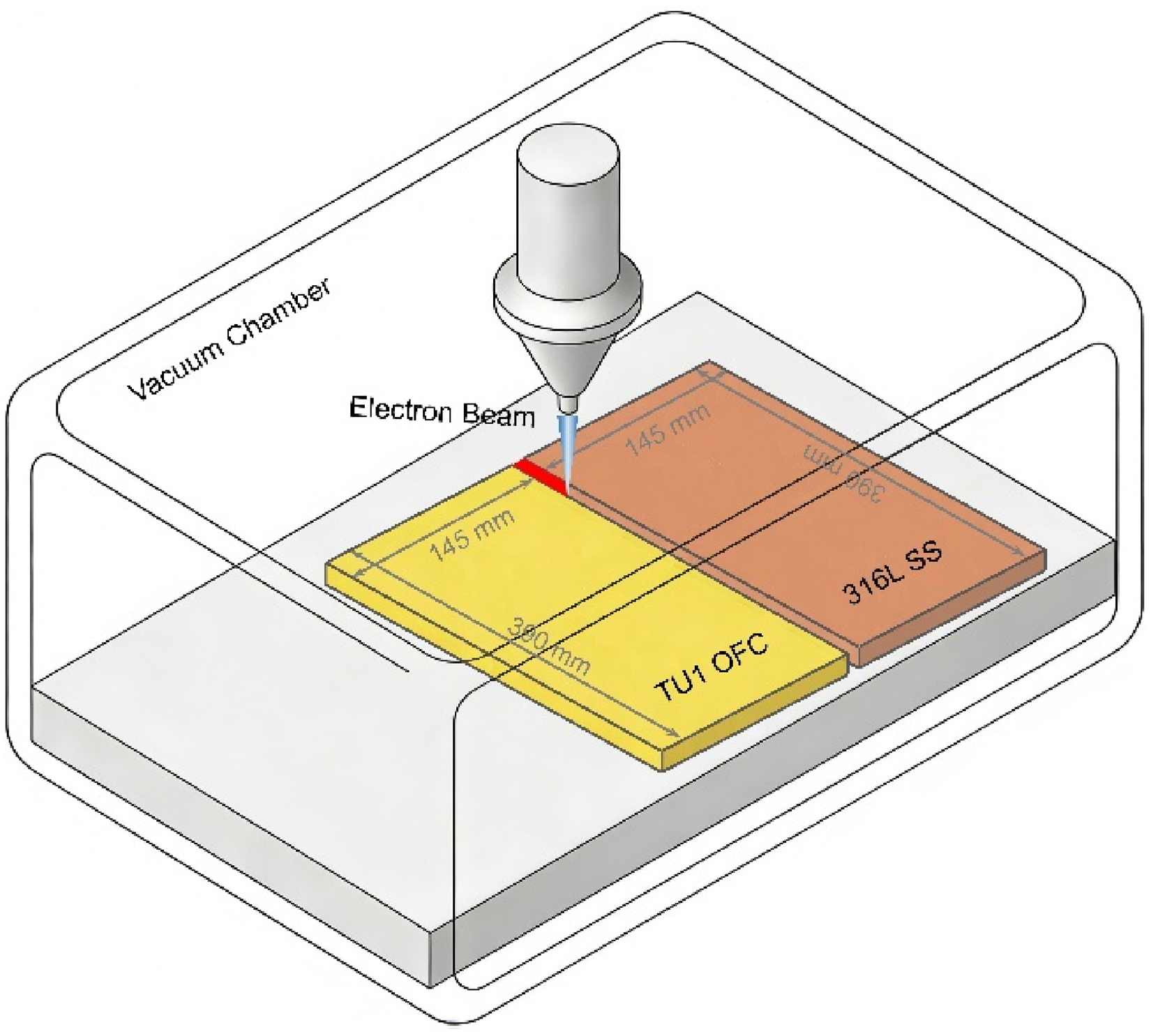
Schematic diagram of vacuum electron beam welding of TU1 oxygen-free copper (TU1 OFC) and 316L SS.
Vacuum electron beam welding process
Prior to welding, the adjacent surfaces of the plates were ground using 120-grit silicon carbide paper and then chemically cleaned with acetone to remove surface grease and contaminants. Subsequently, to further eliminate surface oxides, the TU1 OFC plate was treated using vinegar immersion and the 316L SS plate underwent pickling and passivation. A ZD150-60C CV66M vacuum electron beam welding system was employed in this study. The equipment featured a large vacuum chamber measuring 7200 mm × 3550 mm × 2600 mm, a maximum beam power of 60 kW and an operating vacuum level of ∼1.7 × 10⁻⁴ mbar. The welding parameters employed were an accelerating voltage of 150 kV, a welding speed of 15 mm/s and a beam current of 10 mA. The beam was operated in continuous mode, producing a spot-shaped beam that was precisely aligned with the butt joint line. The focus position was set at the workpiece surface, and no beam offset was applied. A square butt joint configuration without edge preparation was adopted for the thin plates of the TU1 OFC and 316L SS (Figure 1).
Mechanical test
Flat dog-bone tensile specimens were sectioned from the BMs and EBWed metals with a gauge length of 25 mm and a cross-section of 6 mm × 1 mm, respectively. Then, quasi-static uniaxial tensile tests were carried out on the material testing machine (YQN-20 kN) with the strain rate of 5 × 10⁻⁴ s−1 at room temperature. Prior to testing, tensile specimens were speckle-patterned with black and white inks to enable precise strain analysis via the Digital Image Correlation (DIC) technique. Throughout tensile testing, digital image acquisition of the speckle-patterned tensile specimens was performed continuously at 10 Hz using a CCD (Charge Coupled Device) camera (AVT Guppy Pro F–201B). Then, these processed images enabled DIC strain analysis, with global tensile strain quantified precisely using the virtual extensometer function within the DIC software (VIC-2D, Correlated Solutions). The microhardness measurements across the weld cross-section were made on the mirror finish specimen using a microhardness tester (Qness 10A+). The indents were positioned at a load and dwell time of 1 kgf and 10 s, respectively.
Microstructural characterisation
After welding, specimens for microstructural characterisation were sectioned from the welding joint along the cross-sectional direction using wire electrical discharge machining. The obtained specimens were initially ground and polished, followed by cleaning with anhydrous ethanol to ensure a pristine surface. Microstructural morphology and chemical composition were measured via field emission electron scanning electron microscopy (FESEM5000X) equipped with an energy dispersive spectroscopy (EDS) detector. Crystallographic information of the EBWed specimen was obtained via electron backscatter diffraction (EBSD). The preparation of the EBSD specimen involved initial grinding with SiC paper, followed by a 1-hour mechanical polishing step employing a 0.04 mmol/L silica suspension. Subsequent analysis of the EBSD data was obtained by using HKL Channel 5 software.
Results and discussion
Weld appearances
As a full-penetration joining technique, EBW necessitated that weld pool morphology and penetration depth be considered among the critical indicators of sound weld quality. 19 As shown in Figure 2(a) and (b), the weld seam was straight and the weld width was very narrow, measuring only ∼2.72 mm throughout. Additionally, the weld also exhibited a sound surface morphology characterised by a neat-fish-scale pattern and was devoid of common welding defects such as macroscopic holes, solidification crack and spatter. The attainment of such superior weld integrity was contingent upon a stable weld pool configuration and flow regime, facilitated by the appropriate selection of welding parameters. Figure 2(c) illustrates the dog-bone tensile specimens machined from the EBWed joint and two base metals, where the weld seam was positioned at the mid-span of the gauge section and loading was applied perpendicularly to it.
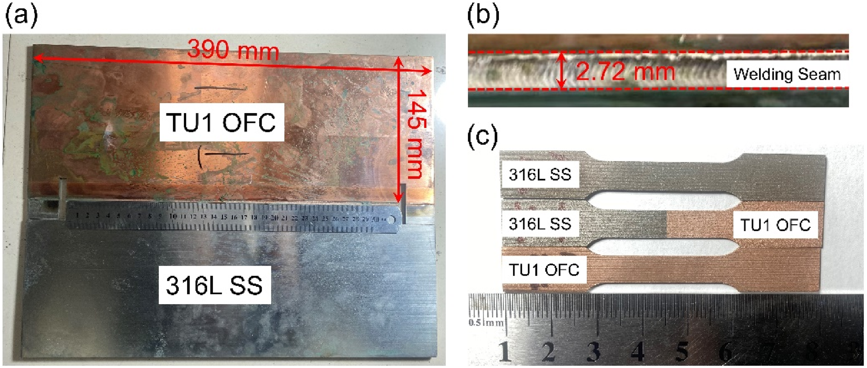
(a) Macroscopic appearance of dissimilar joints; (b) surface morphology of weld seam and (c) dog-bone tensile specimens machined from EBWed joint and two base metals.
Weld microstructures
Figure 3(a) shows the overall cross-sectional morphologies of the TU1 OFC/316L SS dissimilar joints. As can be seen, a complete through-thickness weld penetration was achieved in both plates with the optimised EBW process parameters. The resulting weld joint presented a distinct nail-head profile, featuring a top width of ∼2.59 mm, a central width of ∼1.31 mm and a bottom width of ∼0.52 mm, which was in excellent agreement with the characteristic melt pool geometry of EBW.20,21 Such nail-head morphology arose from non-uniform energy deposition, that is, concentrated energy at the beam centre induced extensive top melting, while energy attenuation via scattering and plasma interaction reduced bottom fusion width.

(a) Overall cross-sectional morphologies of the TU1 oxygen-free copper (TU1 OFC)/316L SS dissimilar joints. (b)–(d) Enlarged views from the rectangular areas in (a). (e) and (f) Typical weld zones are composed of five main areas.
Driven by the chemical potential gradient between the opposing base metals, Cu and Fe atoms underwent mutual diffusion toward the interior of each substrate. As a result, the resultant dissimilar joints featured an interpenetrating microstructure comprising intermixed Cu-rich and Fe-rich zones (Figure 3(a)). At the top of the joint, the Fe-rich zone exhibited a fusion width of ∼2.1 mm, which was nearly twice that of the Cu-rich counterpart (∼1.1 mm), as indicated by the double arrows. This disparity arose because the extremely high thermal conductivity (∼400 W/(m·K)) of copper acted as a ‘heat-absorbing sponge’, rapidly dissipating heat from the interface and thereby restricting lateral expansion of the molten pool into the copper side. Consequently, the increase in fusion width occurred primarily on the stainless-steel side (shown by white arrows). Additionally, the weld joint near the bottom was found to be nearly entirely Fe-rich, despite the fact that the higher density of molten copper (∼8.96 g/cm3) compared to liquid iron (∼7.87 g/cm3) would normally facilitate its downward migration. In fact, the welding pool involved complex and vigorous fluid dynamics. Under the combined influence of Marangoni convection and vapour flow, the dense yet low-surface-tension Cu-rich melt was entrained and transported to the upper regions of the pool. 22 Meanwhile, due to the steep temperature gradient along the depth direction, with the highest temperature at the beam impingement zone near the top surface and progressively lower temperatures toward the bottom region of the pool owing to the heat dissipation through the base metal, the pool bottom exhibited higher viscosity and reduced fluidity compared to the upper region. Then, the intrinsically higher viscosity of liquid iron (∼5.0–8.0 mPa·s) compared to liquid copper (∼3.5–4.5 mPa·s) further restricted convective flow at the pool bottom, thereby limiting the downward migration of Cu-rich droplets. 23
Regarding the distribution morphology, one can observe that coarse Fe-rich islands with dimensions ranging from hundreds of micrometres to millimetres (shown by yellow arrows in Figure 3(a)) and fine spherical Fe-rich particles with sizes of several to tens of micrometres (Figure 3(b) and Supplemental Figure S2(a)) were dispersed within the Cu-rich zone. In contrast, the Fe-rich zone also contained densely distributed spherical Cu-rich particles with dimensions ranging from a few to tens of micrometres and fibrillar Cu-rich filaments (Figures 3(c) and (d) and Supplemental Figure S2(b)). Such morphological features indicated that the interdiffusion layer possessed distinct structural characteristics on either side of the joint regarding the size, morphology and volume fraction of the heterogeneous phase precipitates, which was primarily attributed to the differences in the diffusion rates of Fe and Cu elements. The results suggested that the Fe element exhibited lower migration resistance and longer diffusion distances into copper. Indeed, the intrinsically low viscosity and excellent fluidity of liquid copper enhanced the diffusivity of the Fe element within the copper melt. 24 Concurrently, vigorous Marangoni flow and turbulence in the upper region of the weld pool, caused fine Fe-rich droplets to be readily elongated, fragmented and aligned along streamlines under the influence of strong shear flow. 25 Conversely, the high viscosity and wide solidification range of liquid iron prevented coalescence or deformation of Cu-rich droplets, leaving them pinned between dendrites or solidified as isolated spheres.
The typical weld zones along the TU1 OFC and 316L SS sides could be divided into five main areas based on the distinguishing grain morphologies, including TU1-BM (base metal), TU1-HAZ (heat-affected zone), FZ (fusion zone), 316L-HAZ and 316L-BM, as shown in Figure 3(e) and (f) and Supplemental Figure S2(c) and (d). It was worth noting that the fusion line distinguished the FZ from the narrow HAZ. Obviously, the TU1-HAZ exhibited significant grain coarsening compared to the TU1-BM due to the thermal effect during welding. However, the 316L-HAZ indicated negligible changes in grain size and morphology relative to the 316L-BM. This stability was interpreted as a consequence of the relatively short thermal exposure time on the steel side due to the high cooling rate inherent to the EBW process.
Then, the microstructure at the fusion zone was further investigated in detail by using a combination of SEM and EDS chemical analyses, as shown in Figure 4. It was evident that the Cu-rich and the Fe-rich zones were consistently composed of both Cu and Fe elements. These atomic-level mixing was the result of interdiffusion of alloying elements, further demonstrating that this dissimilar welding achieved a good metallurgical bond. Overall, the fusion zone exhibited a higher proportion of Fe (∼56.35 at.-%) than Cu (∼43.65 at.-%) owing to the higher diffusivity of Fe and the partial evaporation of Cu at elevated temperatures under the applied vacuum level (the evaporation temperature of Cu was ∼1035 °C, lower than that of Fe at ∼1195 °C).8,26

Scanning electron microscopy and energy-dispersive X-ray spectroscopy (SEM−EDS) maps in fusion zones.
Grain structure
As shown in Figure 5(a), a site-specific EBSD investigation was conducted on the bottom of the fusion zone with the aim of elucidating the variations in grain size, morphology and crystallographic orientation among different microstructural zones, including the TU1-HAZ, FZ and 316L-HAZ. It was apparent from the corresponding elemental distribution maps that no diffusion of heterogeneous elements was observed within either HAZ. The inverse pole figure (IPF) map in Figure 5(b) revealed a marked gradient in grain size and morphological type within the dissimilar welding joint. Here, the regions of interest (ROIs) for grain size analysis were defined based on the distinct microstructural zones labelled in Figure 5(b). For each ROI, a minimum of 150–200 grains (comprising all grains from both phases) were analysed to ensure statistical representativeness of the grain size distribution.

(a) Scanning electron microscopy and energy-dispersive X-ray spectroscopy (SEM−EDS) maps of Fe and Cu elements in the region of interest. (b)–(d) Corresponding inverse pole figure map, phase map and kernel average map. (e)–(g) Grain size distribution of three regions from (b). (h) Pole figures of the fusion zone.
Evidently, both heat-affected zones, designated ‘A’ and ‘C’, exhibited a near-equiaxed grain structure, with the average grain sizes of ∼67.84 μm (Figure 5(e)) and ∼32.17 μm (Figure 5(g)), respectively. Region ‘B’ corresponding to the FZ indicated course columnar grains spatially positioned on the fusion line with the fine grain growth.27,28 Obviously, such columnar grains had a consistent grain growth in line with the direction of welding heat flow, that is, growing radially perpendicular to the fusion line. Such a grain characteristic could be understood by considering both nucleation site and growth direction. Firstly, during the solidification of the welding pool, the liquid metal did not undergo independent nucleation. Instead, it grew epitaxially from the partially unmelted grains of the base metal at the fusion line, since the base metal grains provided a ready-made ‘substrate’, requiring the minimum energy for nucleation. 29 Secondly, the grain growth direction followed the maximum thermal gradient, which was always oriented perpendicular to the fusion line and pointed toward the welding centreline. The FZ had an average grain size of ∼75.03 μm (Figure 5(f)), while displaying a spatial heterogeneity with grains coarsening progressively toward the welding centre and upper portion. It was mainly attributed to the comparatively milder temperature gradients (G) and reduced solidification velocities (R) in these regions relative to the pool bottom near the fusion line. 30 Moreover, the Cu-rich particles in the FZ were predicted to be ∼18.6 µm in size, as shown in Figure S3 in the Supplemental Material.
Particularly, the fusion line indicated a substantial number of very fine equiaxed grains. This phenomenon was attributed to two primary factors. First, the EBW corresponded to a high-energy-density and rapid-cooling process. The molten metal near the fusion line solidified almost instantaneously, leaving insufficient time for grain growth. According to classical solidification theory, the higher cooling rate resulted in a finer grain structure. 31 Second, in dissimilar metal welding, a steep compositional gradient developed near the fusion line. Cu and Fe atoms exhibited limited mutual solubility in the liquid state, and then solute redistribution during solidification might generate a constitutional supercooling zone. Such constitutional supercooling activated additional nucleation sites, promoting the formation of numerous fine equiaxed grains along the fusion line, rather than allowing columnar grains to grow continuously across the interface. 27
According to the Fe–Cu binary phase diagram, Fe and Cu elements tend to form continuous solid solutions with a reluctance to produce intermetallic compounds. 32 Consequently, as evidenced by the phase distribution map in Figure 5(c), the microstructure of the dissimilar welding joint consisted predominantly of Fe-rich and Cu-rich phases. Figure 5(d) shows the kernel average map (KAM) utilised to characterise the distributions of residual strain in various parts of the dissimilar welding joint. Owing to incomplete stress relief annealing of the base metal after rolling and the more rapid cooling during welding, the TU1-HAZ region exhibited significantly higher KAM values compared to the 316L-HAZ region, that is, the higher residual strain or dislocation density in the TU1-HAZ region. The FZ also exhibited considerable localised residual strain, probably attributed to the steep temperature gradient and fast cooling rate during solidification. Moreover, the pole figures (Figure 5(g)) revealed that neither the Cu-rich nor the Fe-rich phase displayed a preferred crystallographic orientation, which stemmed from the profuse nucleation events triggered by liquid-phase separation and the stirring-induced disruption of competitive grain growth. 33
Weld mechanical properties
As shown in Figure 6, the microhardness of the TU1 OFC/316L SS dissimilar joints exhibited a generally increasing trend from the TU1 OFC side to the 316L SS side. Both base metals had more uniform hardness distributions (TU1 OFC (∼109 ± 10) HV and 316L SS (278 ± 25) HV) equivalent to their theoretically expected hardness values. The average hardness value measured in the FZ was ∼112 ± 20 HV. Furthermore, it was noteworthy that the HAZ on both sides exhibited lower hardness than the respective base metals, as indicated by green circles. Such softening might arise from the thermal-induced recovery and recrystallisation that mitigated pre-existing cold work hardening. Based on this, it could be reasonably inferred that the HAZ widths on the TU1 OFC side and the 316L-SS side were ∼1.25 and 0.580 mm, respectively.
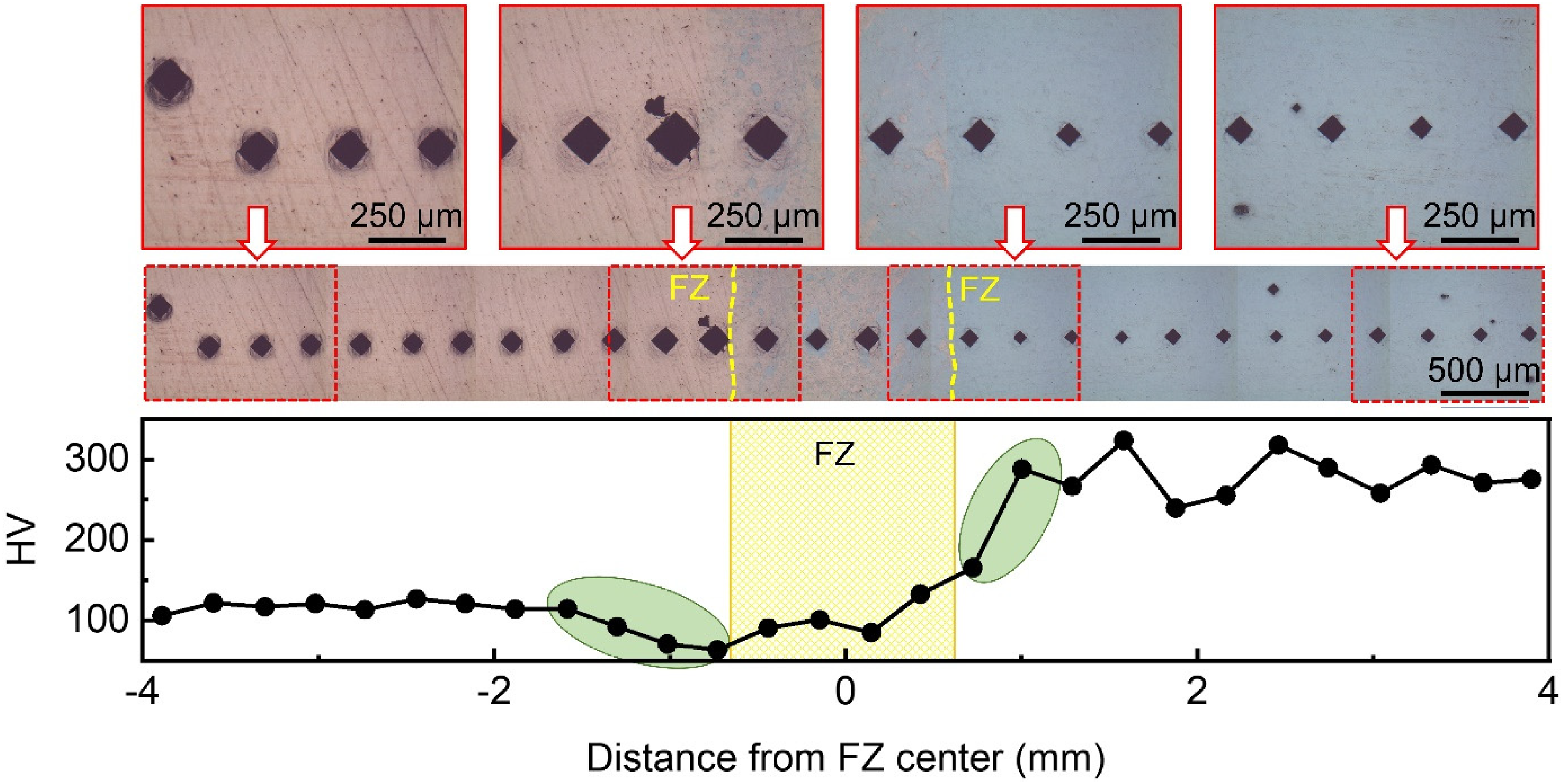
Microhardness of the dissimilar joints.
Figure 7(a) shows the engineering stress–strain curves of the two base metals and EBWed specimen, where the extracted yield strength (YS), ultimate tensile strength (UTS), and elongation (EL) were summarised in Figure 7(b). Obviously, the 316L SS specimen exhibited typical tensile properties with YS of ∼257.8 MPa, UTS of ∼564.3 MPa and EL of ∼83.8%. However, the TU1 OFC specimen exhibited a high yield strength (∼289.5 MPa) alongside a markedly low elongation (∼4.8%), which was probably attributed to incomplete pre-welding annealing during its manufacturing process, leaving significant residual strain (i.e. high dislocation density). In general, the majority of fusion welding processes usually lead to the growth of abnormal grain or the formation of intermetallic compounds during solidification and thus result in the reduced tensile properties of the welding joint. 34 Nevertheless, according to the Fe–Cu binary phase diagram, no intermetallic compound was expected to form in the Cu–Fe system. 9 Therefore, the welded joint might not exhibit poor mechanical properties.
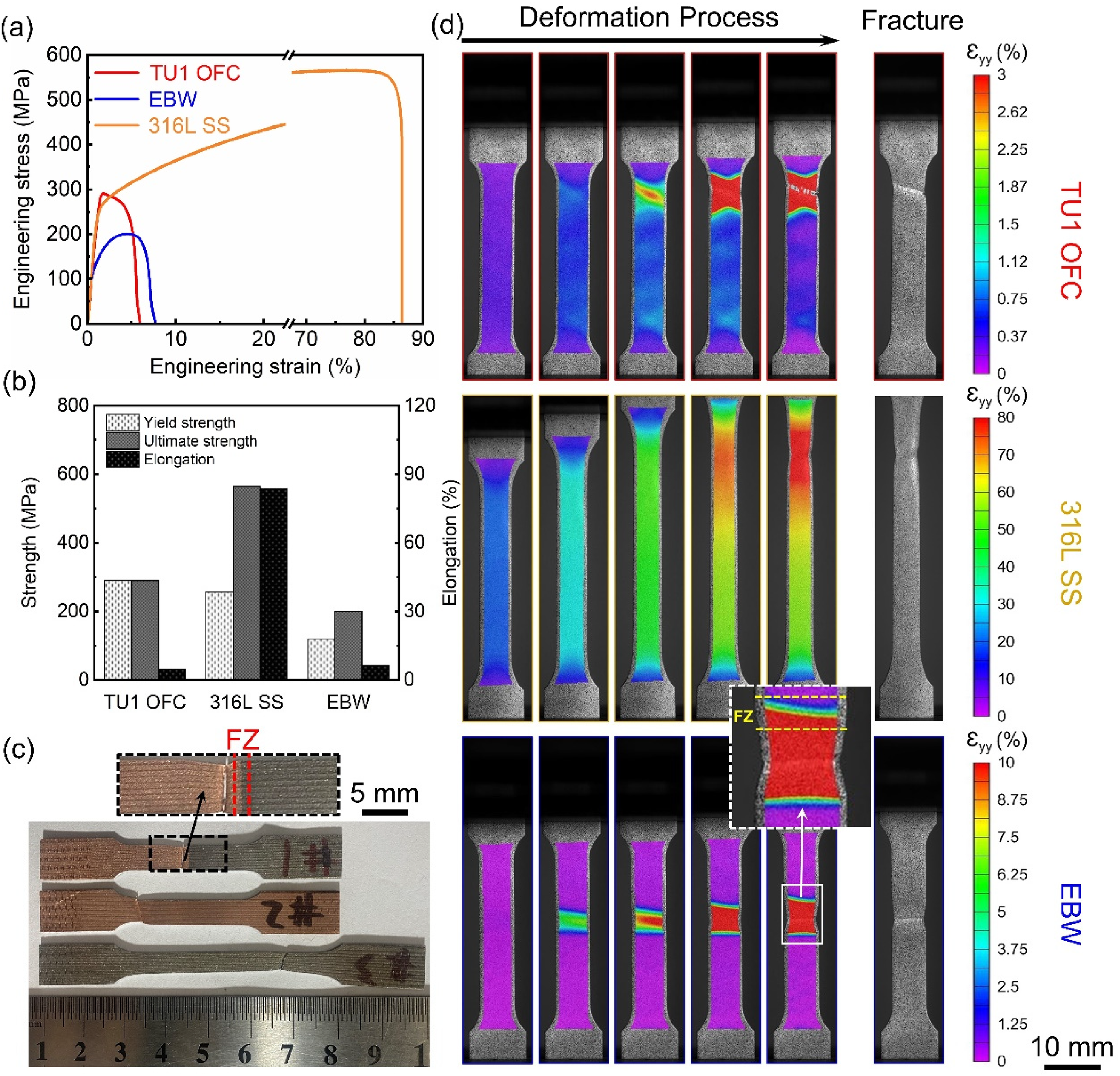
(a) Engineering stress–strain curves of the two base metals and EBWed specimen. (b) Extracted yield strength, ultimate tensile strength and elongation. (c) Specimens after fracture and a magnified image of the fracture surface morphology. (d) Local strain evolution in the tensile specimens.
Figure 7(c) indicates that such a 316L SS/TU1 OFC dissimilar welding specimen fractured on the TU1 OFC side instead of the welding joint. The fracture location was ∼2.5 mm away from the weld centreline. Based on the HAZ width derived from the hardness data, it could be inferred that the failure location of the dissimilar joint occurred within the weak and softened TU1-HAZ. Evidently, the tensile properties of the weld reported in this study were closely aligned with the TU1 OFC of the dissimilar material system, with their YS and EL of ∼123.5 MPa and ∼6.8%. Local strain distribution in the tensile specimens obtained from the DIC technique was shown in Figure 6(d), where the tensile axis was oriented vertically in the image and the colours superimposed on the tensile specimens represented the engineering equivalent strains at local points. One can find that the pronounced strain localisation showing macroscopic necking was observed in all three specimens. The representative fracture surface morphologies of the EBWed specimen (Supplemental Figure S4) indicated the existence of dimples, confirming the ductile nature.
Moreover, it should be noted that the TU1 OFC base metal used in this study was not in a fully annealed state. Its high yield strength (∼289.5 MPa) and low elongation (∼4.8%) indicate significant residual cold work or incomplete pre-welding annealing. Consequently, the tensile properties of the welded joint (YS ∼123.5 MPa, EL ∼6.8%) reflected the behaviour of this specific, non-ideal copper condition rather than that of a standard annealed TU1 OFC. For applications requiring a fully annealed copper base metal, additional pre-weld heat treatment might be necessary. Nevertheless, the fact that failure occurred in the TU1 OFC side (not the welding joint) under this higher-strength copper condition strongly suggested that the EBW joint was mechanically robust and free of brittle intermetallic phases. These findings highlighted the effectiveness of the proposed welding method for achieving strong and reliable dissimilar-metal joints.
Conclusion
In this study, EBW was successfully employed to join TU1 OFC and 316L-SS plates. Defect-free dissimilar joints with full penetration and a characteristic nail-head morphology were achieved using optimised parameters. The fusion zone featured a complex interpenetrating microstructure comprising intermixed Cu-rich and Fe-rich zones, along with dispersed spherical particles and fibrillar filaments. Such a structure resulted from liquid phase separation, Marangoni convection and the differing thermophysical properties of the two materials. EBSD analysis revealed a pronounced grain size gradient with fine equiaxed grains at the fusion line and columnar grains growing epitaxially into the fusion zone. Microhardness increased progressively from the TU1 OFC side to the 316L-SS side, with the fusion zone exhibiting an average hardness of ∼112 HV. Tensile testing revealed that the fracture occurred in the weaker TU1-HAZ rather than the weld joint, with a yield strength of ∼123.5 MPa and elongation of ∼6.8%. Overall, the formation of a sound, defect-free weld microstructure combined with the failure location in the weaker TU1-HAZ demonstrated that EBW was an effective technique for producing reliable copper/stainless steel dissimilar joints.
Supplemental Material
sj-docx-1-stw-10.1177_13621718261458866 - Supplemental material for Microstructure and mechanical properties of vacuum electron beam welded dissimilar TU1 oxygen-free copper to 316L stainless steel
Supplemental material, sj-docx-1-stw-10.1177_13621718261458866 for Microstructure and mechanical properties of vacuum electron beam welded dissimilar TU1 oxygen-free copper to 316L stainless steel by Wei Tong, Lei Yang, Zhuang Zhuo, Jie Tian and Li Liang in Science and Technology of Welding and Joining
Footnotes
Ethical considerations
Not applicable.
Consent to participate
Not applicable.
Consent for publication
Not applicable.
Author contributions
Wei Tong: performed preparation of specimens, analysed data and wrote the paper, Formal analysis and writing–original draft. Lei Yang: performed part of the microstructural characterisations. Zhuang Zhuo: performed the testing of mechanical properties. Jie Tian: performed part of the microstructural characterisations. Li Liang: designed the research. All authors reviewed the manuscript.
Funding
The authors disclosed receipt of the following financial support for the research, authorship, and/or publication of this article: This work was supported by the Natural Science Research Project of Anhui Educational Committee under Grant Number 2023AH051230 and the National Natural Science Foundation of China under Grant Number 52401224.
Declaration of conflicting interests
The authors declared no potential conflicts of interest with respect to the research, authorship, and/or publication of this article.
Data availability statement
The data that support the findings of this study are available from the corresponding author upon reasonable request.
Supplemental material
Supplemental material for this article is available online.
References
Supplementary Material
Please find the following supplemental material available below.
For Open Access articles published under a Creative Commons License, all supplemental material carries the same license as the article it is associated with.
For non-Open Access articles published, all supplemental material carries a non-exclusive license, and permission requests for re-use of supplemental material or any part of supplemental material shall be sent directly to the copyright owner as specified in the copyright notice associated with the article.