
Abstract
The present investigation shows new development on assembled permanent formwork using ultra high toughness cementitious composites with low permeability and high crack resistance. A bidirectional keel formwork is designed to act as surface cover to prevent corrosion of steel reinforcements for structures under aggressive environment. Main attention is focused on mechanical aspects of a reinforced concrete specimen made with permanent formwork in this article. The flexural behavior of specimen is measured with four-point bending test and experimental results are then presented. A method is proposed to predict the load capacity and displacement of specimen and theoretical prediction shows a coincidence with test results. Furthermore, a series of design details and suggestions are discussed. The results of this investigation show that specimen made by ultra high toughness cementitious composite assembled permanent formwork presents higher load-carrying capacity and more ductile behavior compared with reinforced concrete specimen.
Introduction
Durability of concrete structures has become a major concern for new constructions. Continuous rusting together with water absorption and expansion of the rust generate internal stresses that lead to cracking and spalling of the concrete cover (Bentur et al., 1997). The problem arises in part from that the concrete cover of structures under aggressive environment is exposed to water and corrosive agents (e.g. chlorides and carbon dioxide), which induces steel corrosion. Moreover, steel corrosion is a major cause of degradation for reinforced concrete structures and effects the operation of structures.
To prevent the formation of surface cracks and delay the penetration of water and corrosive agents, a feasible method is to construct the member with ultra high toughness cementitious composites (UHTCC), which is also referred to as engineered cementitious composites (ECC) or strain hardening cementitious composites (SHCC). It was proposed by Li and Leung (1992) and was designed with micromechanical principles to achieve the strain-hardening behavior. In UHTCC, the increase in load after first cracking allows the uniform formation of closely spaced multiple cracks along the specimen, with the opening of each crack limited to a very small value (below 50 µm), whose effect on both water permeability and chloride diffusivity can be minimal (Takewaka et al., 2003; Wang et al., 1997). Also, durability of UHTCC has been investigated and reported (Ahmed and Mihashi, 2007; Lepech and Li, 2005, 2006; Maalej et al., 2002; Sahmaran et al., 2007, 2009; Sahmaran and Li, 2008; Yang et al., 2009). As a relatively new construction material recently proposed in China, a large number of experimental studies have been carried out on the performance of UHTCC (Xu and Li, 2010), including mechanical properties (Li and Xu, 2009, 2011; Xu and Cai, 2010a), durability (Xu and Cai, 2010b; Xu and Liu, 2010), structural application (Wang, 2011; Xu and Li, 2009), and so on.
Due to that polymeric fibers used in UHTCC are very expensive, normal concrete replaced by UHTCC in the whole structure would lead to significantly higher cost. Partial use of UHTCC material at crucial locations of concrete structures is a strategically effective solution to this problem. In this research, assembled permanent formwork using UHTCC will be designed to replace wooden and steel formwork. This kind of formwork could be used as formwork during the casting of concrete and be employed as a protective layer for reinforced concrete structures to resist the penetration of corrosive agents after construction. In this way, construction efficiency will be improved and concrete structure with a UHTCC layer will be durable. Furthermore, permanent formwork could be widely used in concrete structures, once it could be prefabricated in factory. According to recent reports by Li et al. (2009), Leung and Cao (2010), and Jin et al. (2013), UHTCC is an ideal material for permanent formwork and the bond between UHTCC and concrete, in relation to various surface treatment methods, has been investigated with beam specimens.
This article focuses on the investigation of assembled permanent formwork using UHTCC, which could be employed as a protective layer especially for structures under aggressive environment which require high durability (such as marine environment). In the following, bidirectional keel formwork is designed and specimen made with this formwork is fabricated. Flexural behavior of specimen is measured with four-point bending test and experimental results are presented. Emphasis will be placed on failure process of the specimen and a method proposed to predict the load capacity and displacement of specimen under flexural load. Finally, several design details and suggestions will be discussed.
Design of UHTCC assembled permanent formwork
Due to tensile strain-hardening behavior, multiple cracking phenomena, and notch insensitivity of UHTCC, permanent formworks using UHTCC were designed as blew. According to the experimental results by Leung and Cao (2010), plurality of grooves will be distributed on the inner surface of formwork designed to strengthen the bonding between formwork and the cast concrete.
The structural view of bidirectional keel formwork is illustrated in Figure 1(a), consisting of a rectangular Panel 1 (Figure 1(b)), cross-shaped Connector 2 (Figure 1(c)), T-shaped Connector 3 (Figure 1(d)), and L-shaped Connector 4 (Figure 1(e)). A number of grooves are distributed on the inner surface of Panel 1, while a plurality of grooves are distributed on the outer surface of connecting members. In this design, cross-shaped Connector 2 is used to connect four panels in the middle of formwork. Similarly, T-shaped Connector 3 is used to connect two panels on the edge and Connector 4 for corner. Connecting members were designed to guarantee the connection between panels.
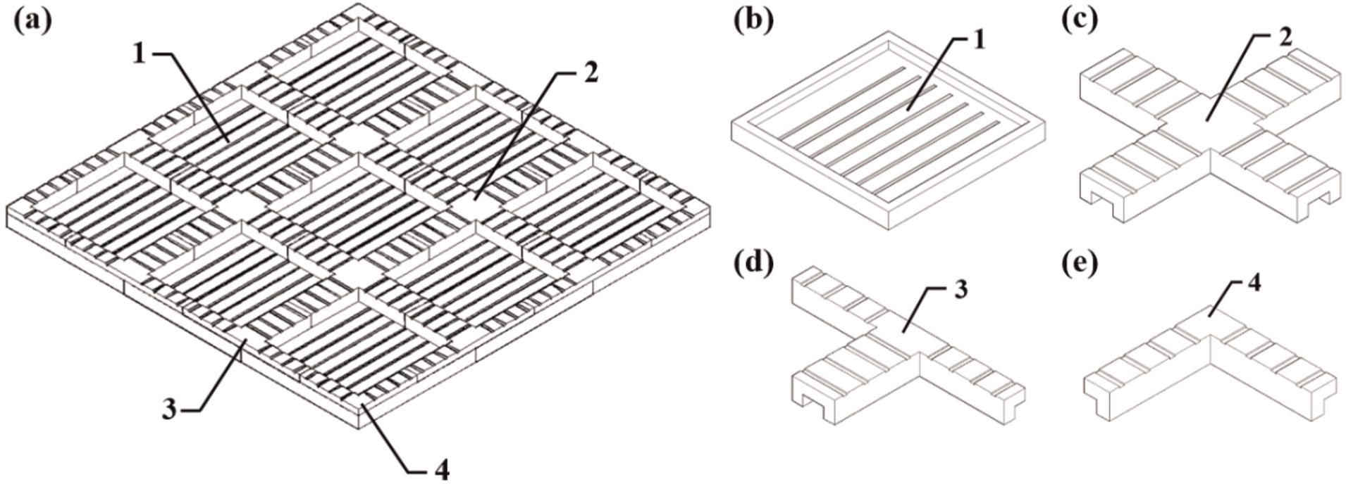
Bidirectional keel permanent formwork. (a) structural view, (b) Panel 1, (c) Connector 2, (d) Connector 3, and (e) Connector 4.
Specimen design and preparation
Material properties
In our experiment, UHTCC was produced using cementitious binders, fine silica sand, water, superplasticizer, and polyvinyl alcohol (PVA) fiber. The binders were composed of ordinary Portland cement and fly ash. The PVA fiber was KURALON K-II REC15 type and fibers added to the matrix were 2% of total composite volume. The whole mixing procedure comprised the following steps in sequence: (1) putting the dry cementitious binders and fine sand into the mixer and mixing for about 1–2 min, (2) adding water and mixing for about 2 min, (3) adding superplasticizer and mixing for about 4–5 min until the fresh mortar showed good flowability and cohesiveness, and (4) adding the PVA fibers manually and mixing for about 5 min until uniform composite was achieved. The above mixing process took about 15 min totally. The compressive strength of UHTCC is 40.2 MPa on average. Direct tension test was conducted at a loading rate of 0.2 mm/min to test the tensile property of UHTCC, and a pair of LVDTs was placed on two sides to measure displacement. The UHTCC mix reached tensile strain about 0.9% with the stress about 3.2 MPa on average, while its first cracking tensile strain was about 0.015% with the stress about 2.8 MPa on average.
For concrete material, the compressive strength is 26.7 MPa on average. Steel bars with a diameter of 10 mm were used in the specimen. The yield strength (f y) obtained by tension test was shown to be 395 MPa. The yield strain of steel bar, which was measured experimentally by electric resistance strain gauge stuck on their surface, was shown to be 0.2%. The elastic modulus E s of steel bar was correspondingly calculated as f y/ε y based on the linear behavior of reinforcement before yield.
Specimen fabrication
The center part of a whole bidirectional keel formwork was tested in this case (shown in Figure 2(a)). In this way, the joining method of formwork can be investigated through four-point bending test. As Figure 2 shows, the formwork was composed of four half panels of bidirectional keel permanent formwork (Figure 2(b)), one connector (Figure 2(c)) and two half connectors. All dimensions of these parts are shown in Figure 2(b) and (c).
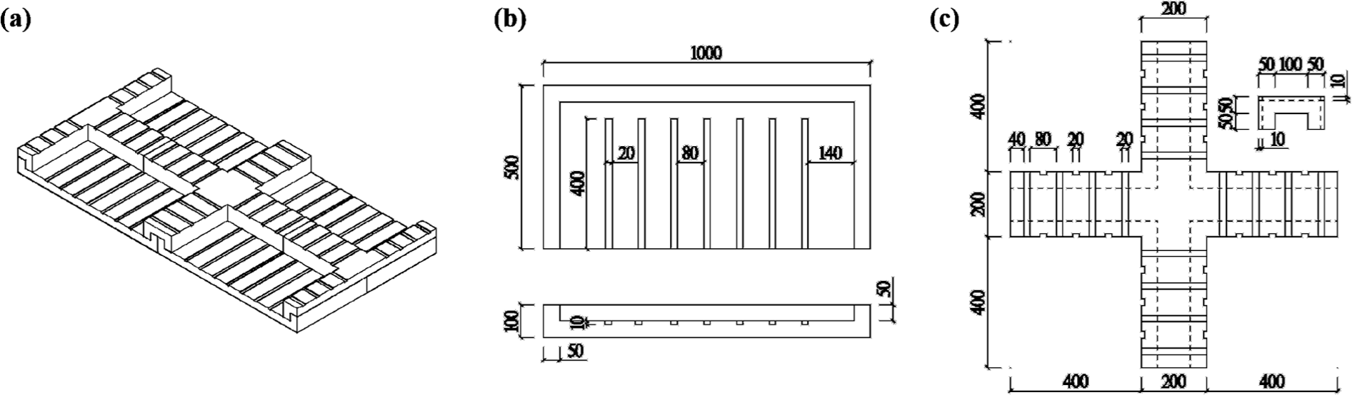
Bidirectional keel permanent formwork. (a) formwork in test, (b) dimensions of half panel, and (c) dimensions of connector.
The fabrication process of specimen using UHTCC formwork is as follows (Figure 3). First, half panels, connector, and half connectors were fabricated and cured for 28 days. Second, members of UHTCC formwork were assembled and put into a wooden formwork with inner dimensions of 2000 mm × 1000 mm × 400 mm. Then, reinforcing mesh, composed of 8 bars mutually parallel longitudinal at 110 spacing and of 17 transversal bars at 110 spacing, was put into a wooden formwork. All the bars used are 10 mm in diameter. Finally, fresh concrete was cast into the wooden formwork to form a specimen with final dimensions of 2000 mm × 1000 mm × 400 mm and cured for 28 days.
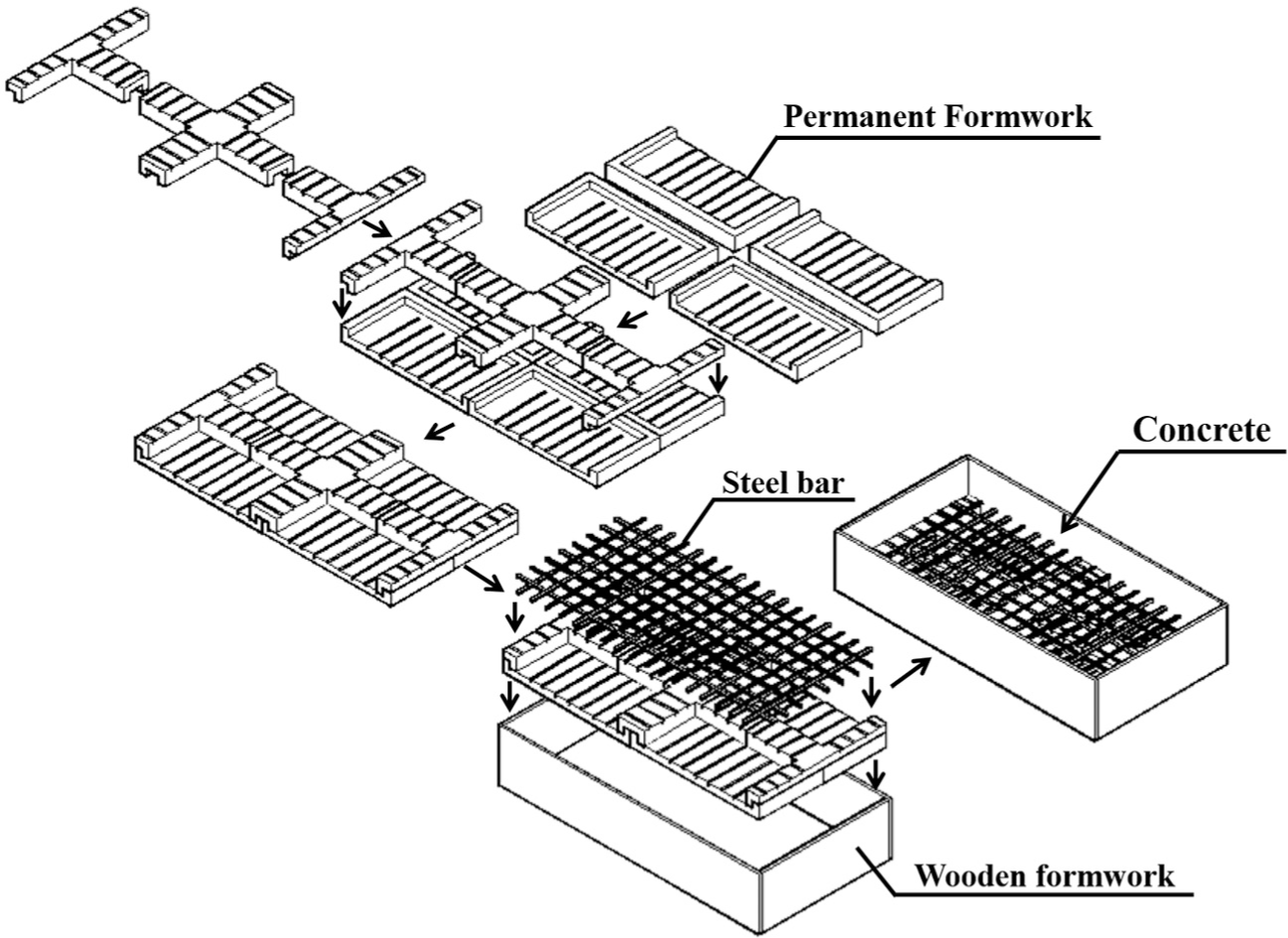
Fabrication process of specimen using UHTCC formwork.
Testing procedure and results
The flexural behavior of the specimen was measured and the test setup is illustrated in Figure 4. The purpose is to determine the strength of the member and measure load versus deflection and load versus crack mouth opening displacement behavior during the test. Also, we are interested in the behavior of the connector.
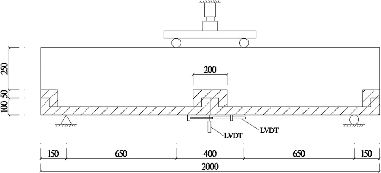
Set-up for the four-point bending test.
The specimen was tested in MTS machines under displacement control of 0.2 mm/min. A pair of linear variable differential transformers (LVDTs) were used to monitor the mid-span deflection and another pair of LVDTs was used to monitor the crack mouth opening displacement between the panels of UHTCC formwork. Due to underestimated load-carrying capacity of the specimen before testing, a 250-kN capacity MTS testing system was used in Test 1 and the specimen did not fail when the load reached maximum value. The load versus mid-span deflection curve and load versus crack mouth opening displacement curve of Test 1 are shown in Figure 5(a) and (b). To measure the failure load of specimen, a 1000-kN capacity MTS testing system was then used in Test 2 and the specimen failed at 323.9 kN, the curves of which are shown in Figure 5(c) and (d).
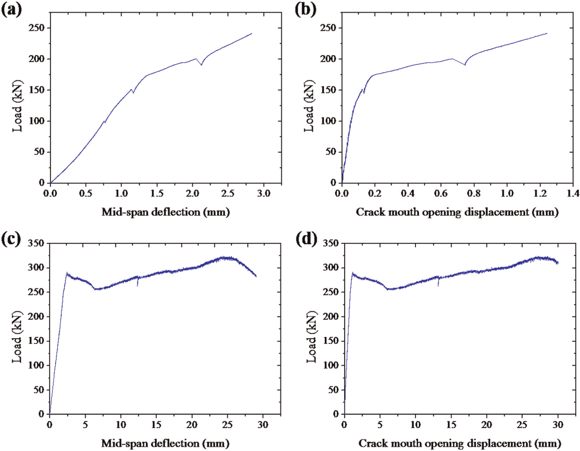
Results of test: (a) load versus mid-span deflection curve of Test 1, (b) load versus crack mouth opening displacement curve of Test 1, (c) load versus mid-span deflection curve of Test 2, and (d) load versus crack mouth opening displacement curve of Test 2.
For the crack patterns at different stages, photographs were taken during testing (Figure 6). The cracks appeared relatively concentrated around the connector of UHTCC formwork. During Test 1, cracks (Figure 6(a)) first appeared at vertical bonding area between connector and concrete and developed vertically before load reached 250 kN. As shown in Figure 6(b), major crack formed across the connector and connected with other cracks formed in Test 1. With increase in the load, the major crack developed and failure pattern is shown in Figure 6(c).
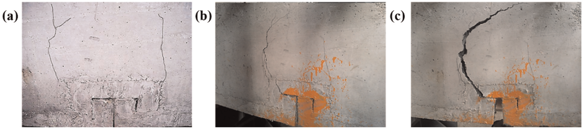
Crack patterns at different loads. (a) 250 kN (Test 1), (b) 290 kN (Test 2), and (c) 320 kN (Test 2).
Theoretical analysis
Assumptions and mechanical model of materials
Theoretical analysis of specimen using UHTCC formwork is based on the following assumptions: (1) cross section keeps plane after deformation, namely, strain along the specimen depth distributes linearly; (2) sliding between steel and concrete is ignored and the bond between concrete and UHTCC is adequate; (3) UHTCC of tensile zone is effective after cracking, until it reaches ultimate strain; and (4) the influence of time-dependent shrinkage and creep on tensile property of UHTCC is not taken into account.
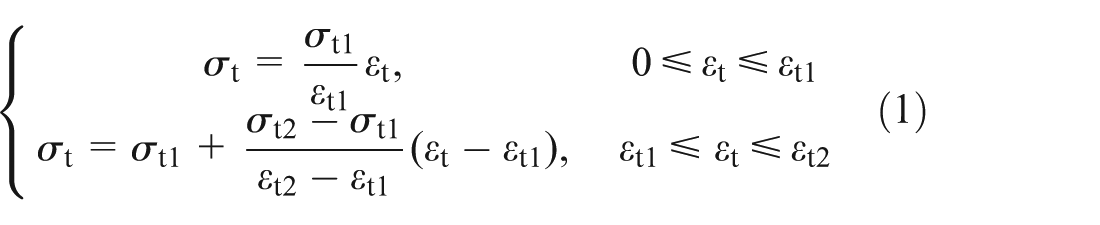
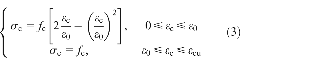
To simplify analysis, bilinear tensile constitutive model of UHTCC was used to describe stress–strain behavior in uniaxial tension (Li et al., 2001). Based on the tensile properties of UHTCC in test, the tensile strength σ t1, tensile strain ε t1, ultimate tensile strength σ t2, and ultimate tensile strain ε t2 of tension constitutive model are 2.8 MPa, 0.015%, 3.2 MPa, and 0.9%, respectively. Tensile stress of UHTCC is expressed in the following expressions
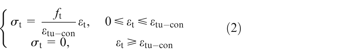
For steel bar, perfect elastic–plastic model is assumed, where f y is the yield strength of steel bar and ε y is the yield strain (ε y = 0.2%; f y = 395 MPa). A simplified model has been used to express stress–strain behavior of concrete in uniaxial tension, where ε tu-con and f t stand for ultimate tensile strain and ultimate tensile stress of concrete in uniaxial tension (f t = 2.2 MPa; ε tu-con = 0.008%)
The compressive constitutive model of concrete proposed by Rüsch is used, in which for ascending segment two-order parabola is assumed, while for descending branch a constant value f c is proposed (ε 0 = 0.2%, ε cu = 0.35%, and f c = 26.7 MPa)
The bond strength between UHTCC and concrete reached 72.8%–98.9% of existing concrete corresponding strength (Wang, 2011).
Bending behavior and failure process of specimen
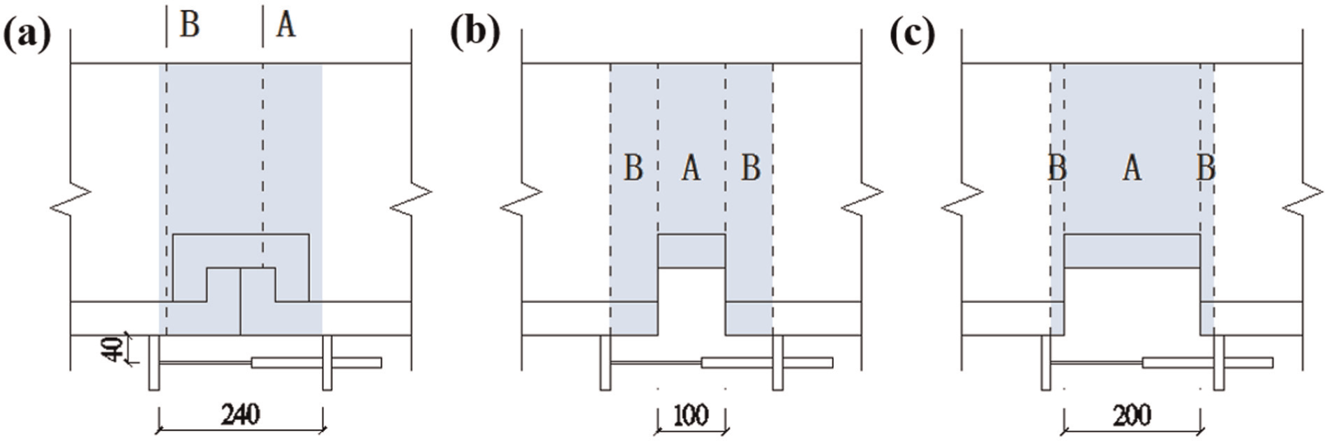
Simplified sections of specimen, in which effect of keel is not taken into consideration, are given to illustrate the bending behavior. Following analysis is focused on three typical sections of specimen shown in Figure 7 and section details are shown in Figure 8. Given a value of ε t (strain of UHTCC at the extreme edge of the zone under tension), the neutral axis height and moment of cross section can be calculated.
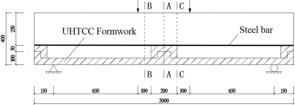
Analyzed sections in specimen.
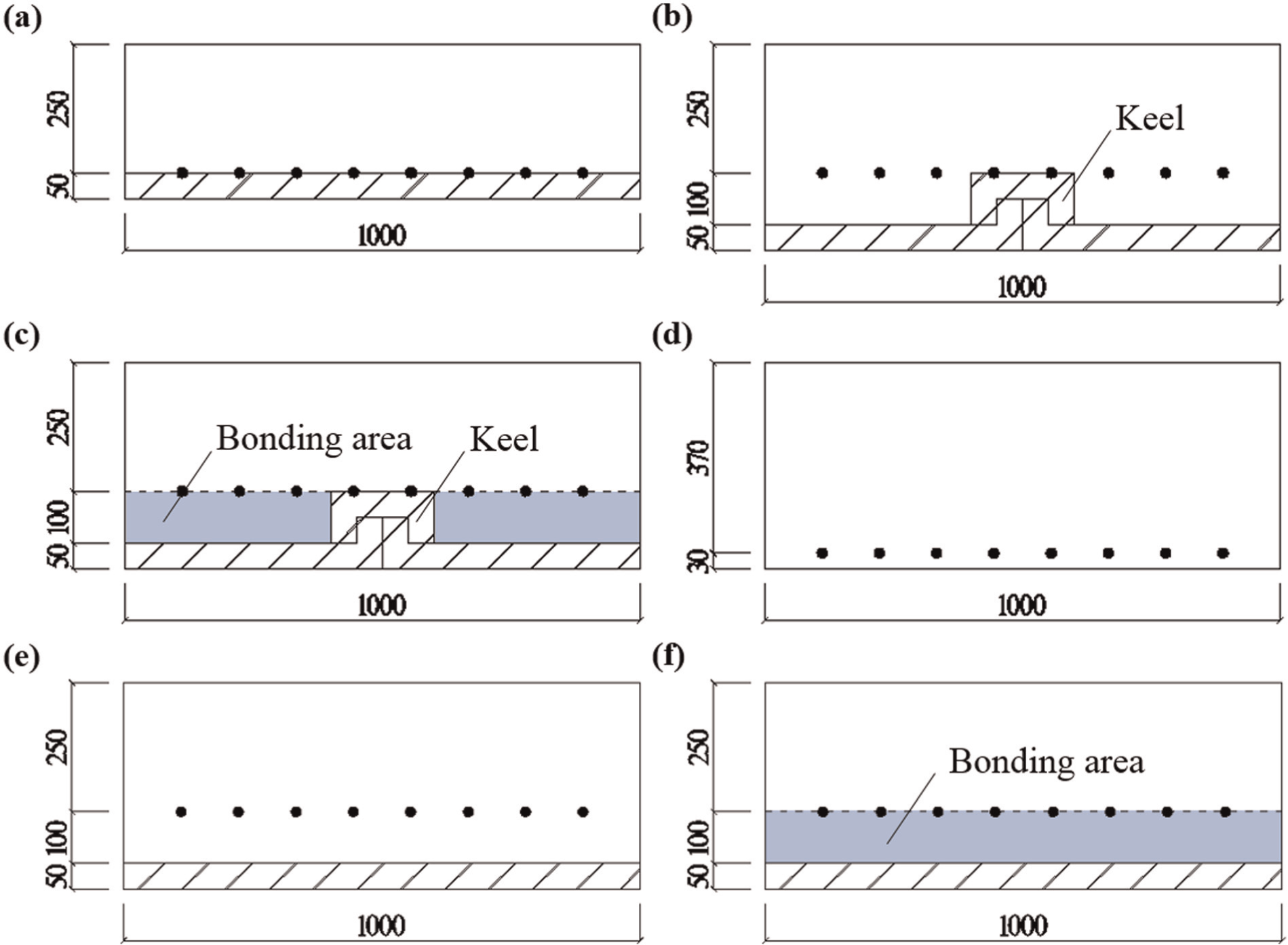
Section details of specimen: (a) Section A, (b) Section B, (c) Section C, (d) section of RC specimen, (e) simplified Section B, and (f) simplified Section C.
For Section A, which is the smallest section of specimen (shown in Figures 7 and 8(a)), calculated yield moment and ultimate moment are 93.1 and 99.5 kN m, respectively. Section B (Figure 8(b)) is a typical section across formwork panels, while Section C (Figure 8(c)) cuts across bonding area between vertical surfaces of connector and concrete. Figure 8(e) and (f) shows simplified Sections B and C, in which influence of keels is not taken into account. Before yield stage, bonding areas of Section C have cracked seriously (Figure 6(a)), leading to a same yield moment (108.5 kN m) of both sections and their ultimate moment (114.8 kN m). However, as tensile strength of UHTCC in keel was not considered, and calculated yield and ultimate moment of simplified sections would be a little lower.
During four-point bending test, first crack of specimen appeared at the bonding area between connector and concrete. This could be explained by that first cracking tensile strain (ε tc) of UHTCC is 2–3 times larger than ultimate tensile strain of concrete (Li and Xu, 2011; Xu and Li, 2009) and bond strength between UHTCC and concrete is lower than tensile strength of existing concrete (Wang, 2011). When strain at the bottom of bonding area reaches 0.728–0.989ε tu-con, specimen (Section C) cracks and corresponding cracking load of specimen ranges from 151.1 to 204.2 kN. As shown in Figure 9, it could be found that calculated range shows a coincidence with experimental results. Moreover, predicted cracking load (165.4 kN) would be very close to experimental one once the bond strength between UHTCC and concrete was assumed to be 0.8f t, which has not been verified by experimental test yet. For cracking load, there is little effect on calculation using the simplified Section C, due to tensile strength of UHTCC in keel replaced by bond strength between UHTCC and concrete.
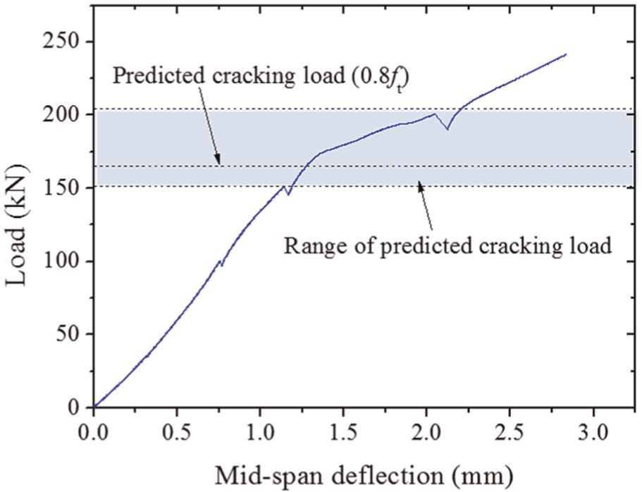
Range of predicted cracking loads of Test 1.
The calculation and test results are summarized in Table 1. Based on the results of four-point bending test and theoretical analysis above, failure process of specimen, including different stages of crack growth, is summarized and illustrated in Figure 10. At Stage I, cracks at bonding area between UHTCC and concrete (Section C) occurred and theoretical load is 151.1–204.2 kN. With increasing in the load, cracks of bonding area propagated and other cracks started to form along the specimen. At the maximum load of Test 1 (Stage II), major crack of specimen was still at bonding area. Meanwhile, multiple cracks could be observed at the bottom of connector and panels due to increase in strain. Then, some of the multiple cracks in connector gradually formed a major crack with the increase in test load. At Stage III (specimen yielded), the major crack moved from Sections C to A and passed through connector. From Table 1, it could be found yield load of Section A is lower than that of Sections B and C, which means steel bars of Section A yielded first and corresponding load (286.6 kN) should be the yield load of specimen. When final failure approached at Stage IV, the major crack (Section A) propagated. Similarly, it could be found that Section A reached ultimate load before Sections B and C reaching yield load and this is why final crack occurred at Section A. Thus, calculated ultimate load of specimen should be 306.2 kN determined by Section A.
Calculation and test results of specimen.
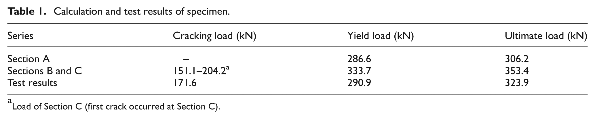
Load of Section C (first crack occurred at Section C).
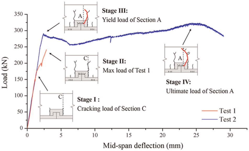
Failure process of specimen in test.
In summary, the predicted cracking load, yield load, and ultimate load of specimen are 151.1–204.2, 286.6, and 306.2 kN separately. Figure 11 shows these loads in test curve and theoretical prediction shows a coincidence with experimental results.
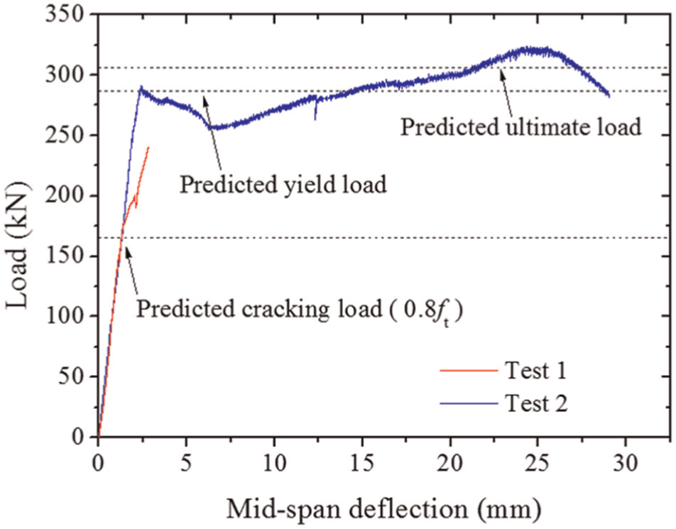
Predicted loads in curve of Test 1.
To reveal contribution of panels and connector to stiffness, a prediction of load versus crack mouth opening displacement curve before yielding (Figure 12) was given. To simplify calculation process of measured region in Figure 13(a), the region was divided into three parts, including two of Section B and one of Section A (Figure 13(b) and (c)) and a bilinear model was used to describe elastic and yield stages. The central part of connector was regarded as Section A in Simplification 1 (Figure 13(b)), of which calculation result is the bilinear curve in Figure 12, while all the connector was regarded as Section A in Simplification 2 (Figure 13(c)). With these two simplifications, range of crack mouth opening displacement at cracking and yield loads could be estimated roughly. The range of calculated crack mouth opening displacement is 0.152–0.280 mm at predicted cracking load, which means the above simplification might be acceptable at a relatively lower load considering that the test result was 0.185 mm. Note that predicted cracking load was assumed to be 165.4 kN (bond strength 0.8f t) in calculation. For predicted yield load, range of calculated displacement is 0.832–0.941 mm, which is a little smaller than the experimental result (1.05 mm). This might be related to the seams between connector and panels, which increased the test deformation at a relatively higher load.
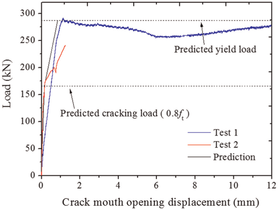
Predicted loads versus crack mouth opening displacement curve of test.
Measured region of crack mouth opening displacement. (a) measured region, (b) Simplification 1, and (c) Simplification 2.
The above analysis focuses on behavior of sections at different stages for specimen with UHTCC formwork. RC specimen with same dimensions and reinforcement ratio is illustrated (Figure 8(d)) and the distance from the extreme fiber under tension to the centroid of reinforcement is 30 mm. The predicted cracking load is 184.6 kN, yield load is 268.0 kN, and ultimate load is 275.3 kN (ε s = 1%), respectively. Compared with RC specimen, it could be concluded that specimen using UHTCC formwork owns higher yield load and load-carrying capacity.
Discussion
According to above study, some details and suggestions for formwork design will be illustrated. Major crack could be arrested by the UHTCC and turned into multiple fine cracks (below 50 µm), whose effect on both water permeability and chloride diffusivity can be minimal (Leung and Cao, 2010; Xu and Li, 2010). Considering this, we expected the notches between panels would be arrested by the UHTCC connector in the initial design of permanent formwork. As shown in Figure 10, multiple cracks could be observed at the bottom of connector during the test before failure load. Yield and ultimate load of specimen were determined by Section A, which was evident by the failure crack. However, vertical notch exists leading to the depth of the section decreased and the cover thickness of tensile steel reinforcement is large, which also lead to inefficient use of materials.
In order to improve the performance of formwork, dimensions of connector and panel should be optimized to obtain higher load-carrying capacity. Considering load capacity related to position of steel bars, once the thickness of UHTCC layer t 1, t 2, and t 3 (shown in Figure 14) are reduced and t 1 is made larger than t 3, this system would be more efficient. Moreover, based on the study about functionally graded composite beam crack controlled by UHTCC (Xu and Li, 2010), the optimal thickness of UHTCC in composite beam should be about 30 mm in consideration of mechanical aspects, durability, and economic efficiency. Thus, we could set the thickness of panels as 30 mm and adjust the thickness of connector. For example (Figure 14(b)), once t 3, t 1, and t 2 is shortened to 30, 35, and 0 mm, respectively, the yield and ultimate load of Section A would be 339.1 and 359.3 kN, while corresponding loads of Sections B and C will be 333.8 and 352.3 kN. In this way, load capacity of the specimen will be determined by Sections B and C with failure crack occurring at panels and the reliability of connection is enhanced simultaneously. The above design suggestions are mainly based on the calculated method and further experiment research is needed to verify.
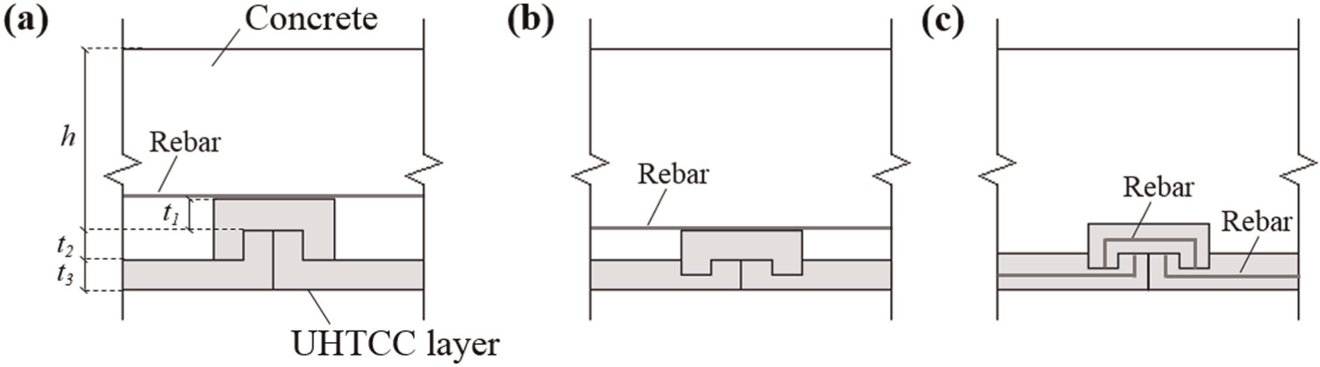
Design details and suggestions: (a) characteristic dimensions of system, (b) optimized system, and (c) reinforced permanent formwork.
From the optimization above, it can be found that load capacity will be changed due to the position of steel bars. However, even in optimized condition, the cover thickness of steel bar is still large (about 65 mm) and steel bar locating at the interface between concrete and UHTCC (interface zone) might be a problem for the bond between steel and matrix. To solve these problems, a reinforced permanent formwork is suggested (Figure 14(c)). With reinforced bars inside panels and connectors, this system will be more efficient and reinforced bars can be protected by UHTCC layer. On the other hand, the UHTCC layer will mainly work as a protective layer with thickness of layer decreased or reinforcement ratio increased.
In terms of cracking load, surface treatment should be applied on the vertical surfaces of connector to improve strength of bonding area in Section C. The surface treatment methods investigated by Leung and Cao (2010) are instructive and corresponding test is essential in the future.
To investigate the crack pattern of connector, the vertical formwork of the system was not fabricated during this test. Without considering above optimization steps of formwork, the system with vertical formwork is shown in Figure 15, which could be applied in the platform of high-pile wharf or other positive moment region of structures under aggressive environment. Because this article is an initial design and first examination of this system, support conditions and connectivity to surrounding structures of this permanent formwork were not provided and should be considered in following investigation. Moreover, the suggested permanent formwork was initially designed for positive moment. In negative moment region, the seams might reduce the carrying capacity and increase the deformation since UHTCC is arranged in the pressure area. Also, more attention should be paid to this aspect in further study.

System with vertical formwork: (a) structural view, (b) corner formwork panel, and (c) edge formwork panel.
For above permanent formwork system, there are still other problems caused by the initial seams. The bottom surface of the formwork without reinforced bars has moisture ingress points along the seams which could be a problem for corrosion. In addition, one of the most damaging environmental conditions to concrete is cyclic freezing and thawing. Although many proofs have been provided for the applications of UHTCC in cold regions (Lepech and Li, 2005; Sahmaran et al., 2009; Xu and Cai, 2010b) and connectors in formwork system could arrest the seams between panels and connectors into multiple harmless cracks, seams of formwork might be disadvantageous under freezing and thawing cycles. To solve these problems, it might be a choice to treat the seams between panels and connectors by grouting method. On the other hand, although UHTCC owns high ductility, the manufacturing tolerance of permanent formwork might still be a problem, which would affect the stiffness of the connection and should be considered in the future.
As this article is a first examination of this system, more testing of the joint detail itself is necessary. The following research might be focused on a more reasonable method to predict load capacity and deformation, the seams between panels and connectors, deformation and load capacity of this system under negative moment, and the suggested reinforced permanent formwork.
Conclusion
In this article, a construction concept for structures under aggressive environment with the use of UHTCC permanent formwork was presented and a bidirectional keel assembled permanent formworks were designed. To investigate the performance of this formwork, especially the connector, flexural behavior of a specimen using UHTCC formwork was measured. Furthermore, a method was proposed to predict the behavior of specimen in test. According to the method, load capacity and displacement were predicted, which showed a coincidence with test results. Using UHTCC formwork, a higher yield and failure load could be achieved in comparison with RC specimen. Based on the failure process of UHTCC formwork, several design details and suggestions for formwork—to change the dimensions, to use reinforced bars in UHTCC layer, and to strengthen bonding area on the vertical surfaces of connector—were discussed to improve the performance of the system.
Footnotes
Declaration of Conflicting Interests
The author(s) declared no potential conflicts of interest with respect to the research, authorship, and/or publication of this article.
Funding
The author(s) disclosed receipt of the following financial support for the research, authorship, and/or publication of this article: This work is supported by the National Key Technology Research and Development Program of the Ministry of Science and Technology of China with grant no. 2012BAJ13B04.