
Abstract
The influence of autoclaved aerated concrete panels on the mechanical properties of fabricated steel frames was experimentally investigated. Two fabricated steel frame specimens, which were with and without autoclaved aerated concrete panels, respectively, were tested under reversed cyclic loads. They were 1/2-scale, two-storey, and single-bay steel frames that were assembled by bolted beam-height adjustable steel beam-to-column connections. The effect of autoclaved aerated concrete panel dimensions on the mechanical behavior of infilled frames was also parametrically analyzed with the proposed numerical models which were verified on the basis of experimental data. The results indicate that the fabricated steel frames, assembled by beam-height adjustable connections, could behave in a ductile manner with sufficient stiffness and strength under cyclic loads; compared with bare steel frames, autoclaved aerated concrete panels could postpone the failure of structures and increase their initial stiffness, peak load, and energy dissipation capacity; moreover, the geometric details of autoclaved aerated concrete panels could significantly change the mechanical properties of infilled steel frames.
Keywords
Introduction
The influence of infill walls on the stiffness, strength, and ductility of framed structures has been known for a long time. However, the positive effect of infill walls on the mechanical improvement of frames is taken as a kind of redundancy and is not calculated in common practical design process, because of the lack of knowledge of the interaction between frames and infill walls (Asteris, 2003). According to American standard ASCE/SEI 7-2010, the stiffening effect of nonstructural walls and partitions is taken into account in the analysis of drift only if substantiating information regarding their effect is available.
Unfortunately, the effect of infill walls is not always positive for the structures in seismic zones, because the dramatic increase in stiffness due to infill walls may reduce the fundamental natural period of structures and change their seismic demand (Asteris, 2003; Asteris et al., 2015; El-Dakhakhni et al., 2003, 2006). In this case, the effect should be considered carefully during seismic design. Chinese seismic design code GB 50011-2010 requires to consider the negative effect of infill walls in seismic design, but it fails to provide a method to describe the effect exactly and expediently. Chinese load code (GB 50009-2012) suggests that the fundamental period of a building can be estimated based on the number of stories. However, Asteris et al. (2015) have found that the fundamental period of infilled frames cannot be predicted using only the height of the frame or the number of stories, and it is a complex problem influenced by various parameters.
Many attempts have been made to study the interaction between infill walls and their boundary frame. Based on the extensive experimental data, the improving effect of infill walls is well verified (Chaker and Cherifati, 1999; Mehrabi et al., 1996; Santhi et al., 2005). And, the widely accepted view about infill walls for now is that they act as compressed struts extending between diagonally opposite corners of frames under lateral loads (Moghaddam and Dowling, 1987; Polyakov, 1960). With the diagonal action of infill walls, frames are stiffened and strengthened, which can lead to the redistribution of damage and the decrease in lateral drift and collapse probability (Ravichandran and Klingner, 2012a, 2012b). However, the experimental works conducted by Vintzeleou and Tassios (1989) and Paulay and Pristley (1992) showed a dramatic reduction in the response of infilled frames under cyclic loads due to the brittle failure of masonry materials. To analyze the complicated interaction behavior of infilled frames, various mathematical models were developed based on the diagonal action concept, which can be roughly divided into single-strut models and multiple-strut models. (Asteris et al., 2012). Holmes (1961) represented the infill wall with an equivalent pin-ended diagonal strut in analysis models, and it was the frequently used single diagonal strut model in early design practices. A mass of empirical or semi-empirical equations have been proposed by following researchers to evaluate the single diagonal strut width, and the equation that has been adopted by most technical guidelines is the one proposed by Mainstone (1974). Compared to other proposed formulas, Mainstone’s formula represents a lower bound of strut width (Asteris et al., 2011). However, as reported by Reflak and Fajfar (1991), Saneinejad and Hobbs (1995), and Buonopane and White (1999), the single-strut model is unable to model the complex behavior of infilled frames exactly, especially for the internal forces in boundary frame members. Therefore, researchers have suggested to replace infill walls with multiple struts including two, three, and more than three struts (Chrysostomou, 1991; Chrysostomou et al., 2002; Crisafulli and Carr, 2007; El-Dakhakhni, 2000, 2002; El-Dakhakhni et al., 2001; Thiruvengadam, 1985). It has been proved that the two-strut model is a desirable model which is more accurate than the single-strut model and less complex than the three-strut model (Asteris et al., 2011; Crisafulli, 1997).
Most of the current investigations are focused on the reinforced concrete frames with masonry infills. The study about the steel frames with lightweight infill panels, which are widely used as economic structural systems in residential buildings, is limited. Autoclaved aerated concrete (AAC) panels are a kind of lightweight infill walls characterized by their cellular structure, which can provide excellent thermal insulation and fire resistance. Owing to their lightweight feature, AAC panels can reduce the seismic inertial force of structures compared with other infill walls. And their noncombustible and fire-resisting properties are of great use in case of fires, which are frequent secondary disaster after earthquakes (Costa et al., 2011). The studies conducted by Tang et al. (2000), Hoenderkamp et al. (2005), and Teeuwen et al. (2008a, 2008b) have shown that precast concrete infill panels may have similar stiffening and strengthening effects on the mechanical property of frames to masonry infills. However, the full-scale cyclic loading test on a three-storey, two-bay by one-bay steel moment frame with external AAC wall cladding shown that the AAC panel cladding contributed little to the stiffness and strength of the structure, even under a very large storey drift of 0.04 rad (Okazaki et al., 2007). On the other hand, AAC panels are always discretely connected to their boundary steel frames (denoted as semi-integral infilled frames), which may result in completely different structural behaviors compared to non-integral and fully integral infilled frames (Teeuwen et al., 2010). Therefore, the first object of this article was to investigate the effect of internal installed AAC panels, which were discretely connected with their boundary steel frame, on the hysteretic behavior of the whole structure.
A kind of bolted beam-height adjustable (BHA) steel beam-to-column connections was developed, and its basic hysteretic behaviors were experimentally studied by Cao et al. (under review). However, the behavior of the steel frame assembled by BHA connections was still unknown. This article provided an insight into this issue. In addition, the influence of AAC panel dimensions on the mechanical properties of infilled steel frames was parametrically studied via numerical models, which were proposed and verified based on experimental results.
Specimen design
Two 1/2-scale, single-bay, and two-storey fabricated steel frame assemblies were cyclic tested. The first specimen (denoted as KJ-1) was fabricated steel frame without infill walls, and its main dimensions were illustrated in Figure 1(a). The second specimen (denoted as KJ-2) was fabricated steel frame with AAC infill panels. Six 300 mm wide and 60 mm thick AAC panels were internally installed in each storey. These AAC panels were discretely connected to their surrounding frame by U-shaped connectors (Figure 2), and the gaps between panels were filled with mortars. The schematic diagram of specimen KJ-2 and its AAC panel serial numbers are shown in Figure 1(b). The steel frame of two specimens was composed of Chinese H200×100×5.5×8 Grade Q235B beams and Chinese H150×150×8×10 Grade Q235B columns. To install infills, an additional Chinese H200×100×5.5×8 Grade Q235B beam was installed on the bottom of specimen KJ-2. Both of the specimens were assembled by BHA connections, and the connection details were shown in Figure 3.
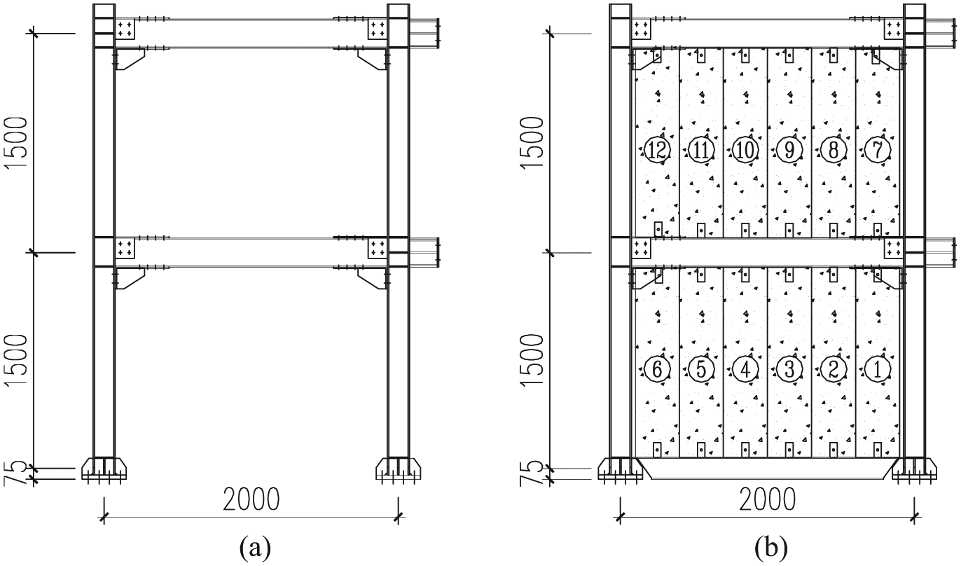
Schematic diagram of specimens: (a) specimen KJ-1 and (b) specimen KJ-2.
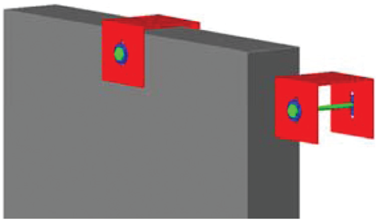
U-shaped connectors for AAC panels.
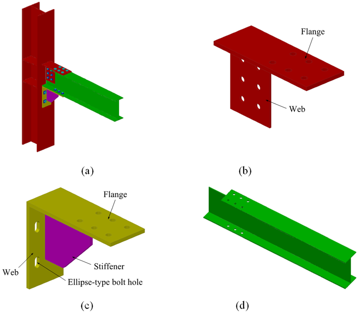
BHA connections: (a) assembly drawing, (b) T-shaped connector, (c) L-shaped connector, and (d) beam end with top frange partial removed.
Test program
Test setup
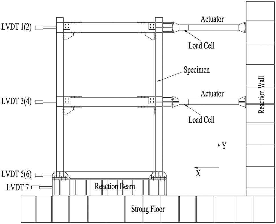
The cyclic test was conducted in the Structural and Earthquake-resistant Testing Center of the School of Civil Engineering at Harbin Institute of Technology, China. The test setup is shown in Figure 4. The column bases of specimens were bolted to a reaction beam which was anchored to the strong floor by high-strength rods. One 300 kN hydraulic actuator for each floor was installed to apply cyclic loads. As shown in Figure 4, a lateral support system was designed to prevent the out-of-plane displacement of specimens.
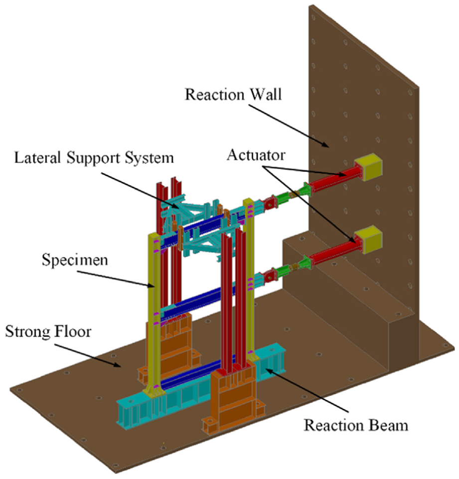
Test setup.
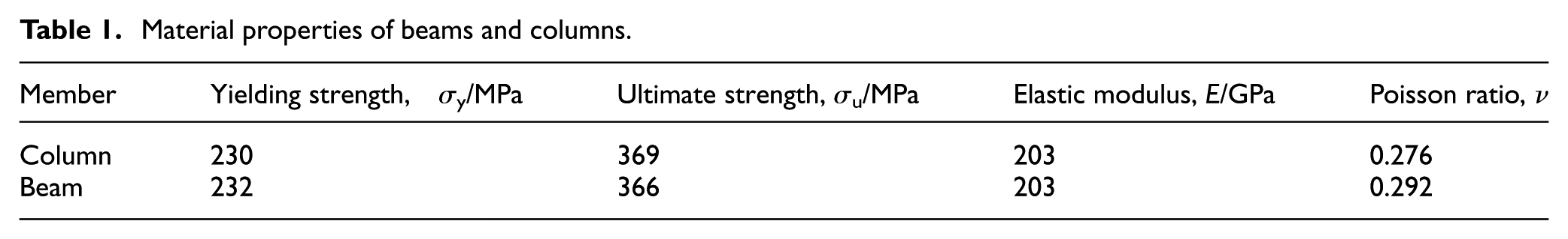
The tensile coupon tests of steel used in specimens were sampled and tested according to Chinese standard GB/T 2975-1998 and GB/T 228.1-2010. The average steel properties are tabulated in Table 1. The average compressive strength and elastic modulus of AAC panels were 4.0 MPa and 1.75 GPa, respectively.
Material properties of beams and columns.
Measuring instrument arrangement and loading protocol
The measuring instrument arrangement is illustrated in Figure 5. The cyclic load applied to each storey was measured by a 300 kN load cell mounted between the specimen and a hydraulic actuator. To record the displacement response of each storey, six linear variable differential transformers (LVDTs) were used. In order to eliminate the negative effect of probable out-of-plane movement in specimens on the measured results, two symmetrical arranged LVDTs were used in each storey (LVDT1–LVDT6 in Figure 5). LVDT7 was used to measure the probable reaction beam slippage.
Arrangement of instruments.
The loading protocol applied to each specimen is shown in Figure 6. The two stories in each specimen were subjected to the same loads during the test, to simulate the lateral load distribution along the adjacent two stories in high-rise buildings. As shown in Figure 6, the specimens were primarily applied with force-controlled loading cycles (P), which have 15 kN (ΔP) increment in every two cycles, until the specimens yielded. And then, the specimens were subjected to displacement-controlled loading cycles which were controlled by the top beam end displacement (δ). The increment (Δδ) in the displacement-controlled loading stage is equaled to 10 mm for every two cycles.
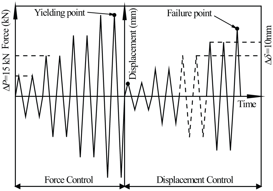
Loading protocol.
Experimental results and discussion
Experimental phenomena
For specimen KJ-1, its steel frame behaved in an elastic manner until the flange of column base yielded at P = ±60 kN, as shown in Figure 7(a), and the yielding lines developed along with loads. Figure 7(b) shows the pattern of yielding lines on the flange of column base when δ reached ±30 mm. When δ equaled to ±40 mm, the web of beam ends begun to yield and the flange of T-shaped connector in BHA connections was buckled, as shown in Figure 7(c) and (d), respectively. At the same load level, a gap was appeared between the L-shaped connector of BHA connections and the column flange (Figure 7(e)). The column base flange begun to buckle at δ = ±60 mm, as shown in Figure 7(f). The test was terminated when δ reached ±80 mm due to the severe local buckling of the column base flange.
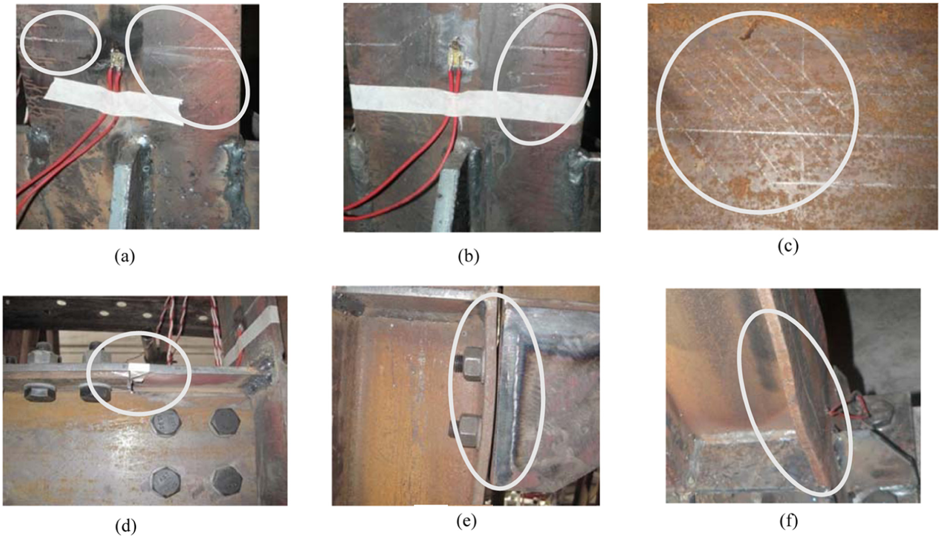
Experimental phenomena of specimen KJ-1: (a) yielding of column base flanges (P = ±60 kN), (b) development of yielding lines at column base flange (δ = ±30 mm), (c) pattern of yielding lines at beam web (δ = ±40 mm), (d) local buckling of T-shaped connector (δ = ±40 mm), (e) gap between L-shaped connector and column (δ = ±40 mm), and (f) local buckling of column base flange (δ = ±60 mm).
As to specimen KJ-2, its steel frame and AAC panels kept elastic until P reached ±30 kN, at which load level cracks were found on the No. 4 panel and the mortars between AAC panels, as shown in Figure 8(a). Cracks begun to appear on the other AAC panels when P was ±45 kN, and these cracks were concentered near to U-shaped connectors (Figure 8(b)). The yielding line pattern on the flange of column base is shown in Figure 8(c) (δ = ±30 mm). As shown in Figure 8(d), the AAC panels crushed and begun to spall after δ reached ±60 mm. At the same time, more yielding lines were appeared on the flange of column base (Figure 8(e)), and the web of beam also begun to yield (Figure 8(f)). The flange of column base buckled when δ reached ±70 mm, as shown in Figure 8(g). The test was stopped at δ = ±130 mm, because the loading limit of the actuator was reached. Meanwhile, the flange in column bases was also buckled badly.
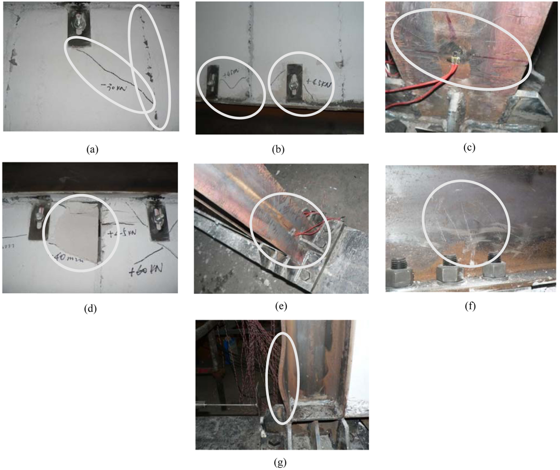
Experimental phenomena of specimen KJ-2: (a) cracks at No. 4 AAC panel (P = ±30 kN); (b) cracks at other AAC panels (P = ±45 kN); (c) yielding line pattern at the flange of column base (δ = ±30 mm); (d) crushing and spalling of AAC panels (δ = 60 mm); (e) developing yielding line pattern at the flange of column base (δ = ±60 mm); (f) pattern of yielding lines at beam web (δ = ±60 mm); and (g) local buckling of the flange of column base (δ = ±70 mm).
Comparison of hysteretic curves
As the two hydraulic actuators in each specimen provided the same force during the tests, the bottom storey of each specimen was subjected to more inter-storey shear force than the top one, and the bottom storey became the critical storey in each specimen. Therefore, the analyses in this section and following sections were based on the experimental data of the bottom storey in each specimen.
Figure 9 shows the relationship of inter-storey shear force (F) and inter-storey drift ratio (θ) in the bottom storey of the two specimens. Both of the two specimens possessed plump hysteretic curves without any pinch phenomenon, which means the steel frames assembled by BHA connections could exhibit stabile hysteretic properties under cyclic loads. For the two specimens, the loading was terminated when their column bases were buckled badly. Although plastic hinges were formed on the buckled column bases, the steel frame of the two specimens still had enough redundancy to sustain lateral loads. Therefore, no degradation of inter-storey shear forces could be observed in the hysteretic curves (Figure 9). As shown in Figure 8(a), (b), and (d), AAC panels took part in carrying lateral loads together with steel frames. Under the same beam end displacement, the steel frame infilled with AAC panels could undertake more load than bare steel frames. That is the reason why specimen KJ-2 had a more plump hysteretic curve than specimen KJ-1, as shown in Figure 9.
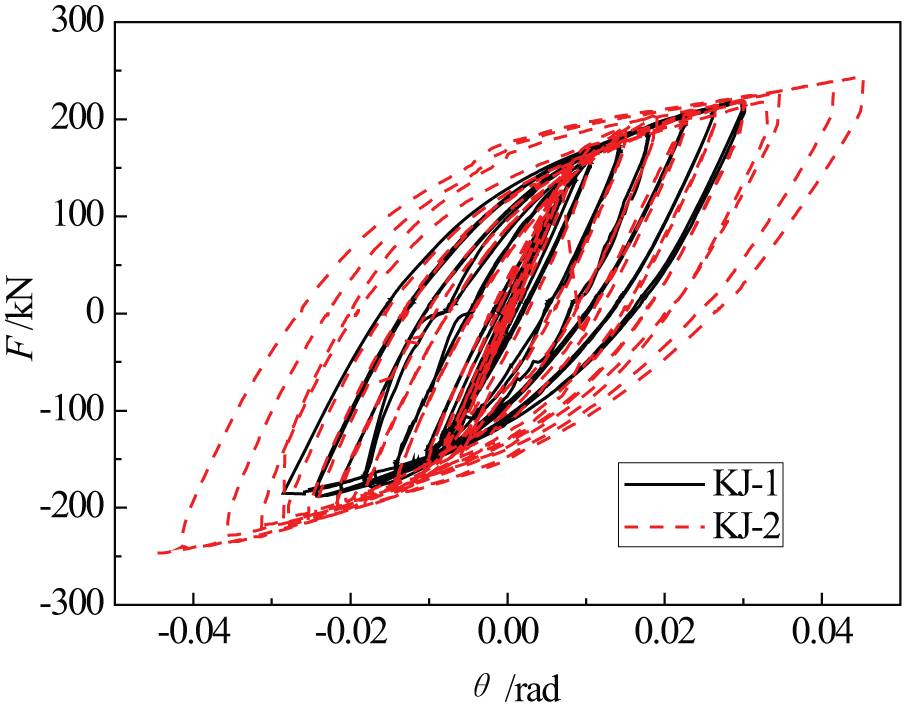
Comparison of hysteretic curves for specimens (bottom storey).
Comparison of hysteretic properties
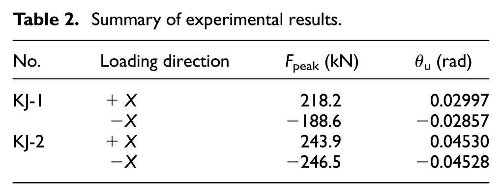
The peak load (Fpeak) and ultimate storey drift ratio (θu) of specimens were summarized in Table 2, where the ultimate storey drift ratios were taken as the maximum storey drift ratio in each loading direction during the tests. The comparison of scant stiffness degradation curves for the two specimens is illustrated in Figure 10. Because of the contribution of AAC panels, specimen KJ-2 possessed a higher initial scant stiffness, peak load, and ultimate storey drift, which indicates that AAC panels could improve the mechanical properties of structures and postpone their failure. As shown in Figure 10, the scant stiffness of the two specimens was degraded because more and more structural components in specimens yielded with load increase. When AAC panels gradually cracked and quit from the co-work with steel frames, the stiffening effect of AAC panels on the lateral stiffness of specimen KJ-2 was reduced. And, the final scant stiffness of the two specimens was similar.
Summary of experimental results.
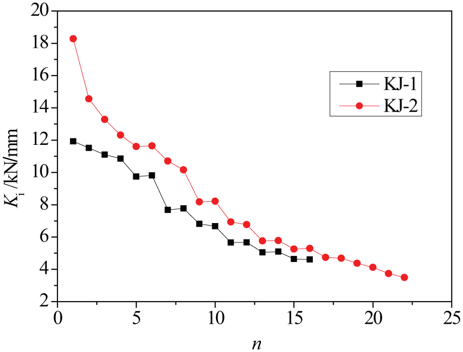
Comparison of scant stiffness (bottom storey).
The result described above also demonstrates that the steel frames assembled by BHA connections could provide sufficient lateral stiffness and load carrying capacity to resist seismic loads.
Comparison of energy dissipation capacity
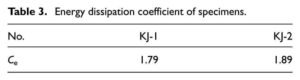
To measure the energy dissipation capacity of the two specimens, energy dissipation coefficients (Ce) were calculated and tabulated in Table 3 (JGJ 101-2015). It shows that all the steel frames assembled by BHA connections could exhibit good energy dissipation capacity. Compared with the bare steel frame, infill walls could take part in the energy dissipation of structures.
Energy dissipation coefficient of specimens.
Parametric analyses of AAC panel dimensions
Finite element models
Based on the experimental data, a numerical model was proposed using finite element software package ANSYS (Asteris et al., 2013). The beams and columns in steel frames were modeled by solid element SOLID95. AAC panels were modeled by solid element SOLID65. The interaction between AAC panels and surrounding steel frames was modeled with contact element CONTAC174 (TARGE170). The U-shaped connectors for AAC panels were replaced by three-dimension spring element COMBIN14. Figure 11 shows the mesh model for specimen KJ-2, and the mesh model for specimen KJ-1 could be obtained by removing the AAC panels and the bottom beam.
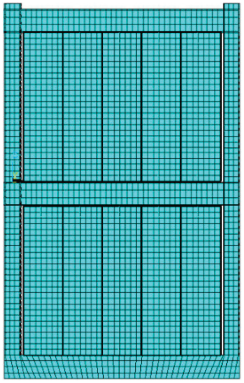
Mesh model for specimen KJ-2.
As shown in Figure 12, the constitutive relation for steel members was a multi-linear kinematic hardening model, which was determined based on the coupon test results. Equations (1) and (2) depict the dimensionless constitutive relation for the AAC material.
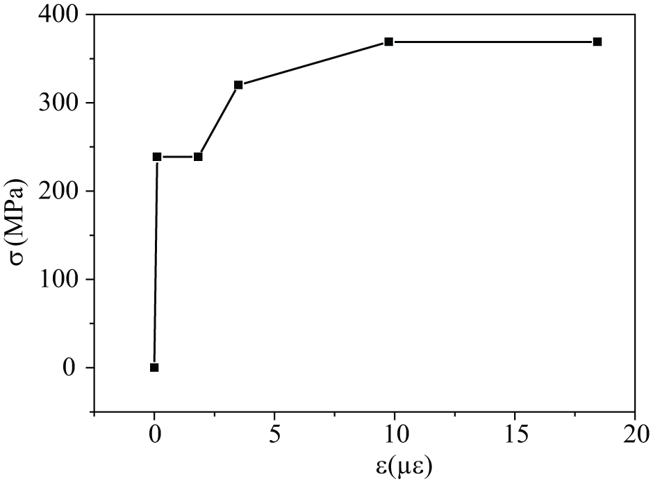
Constitutive relation for steel members.
For ascent stage

For descent stage
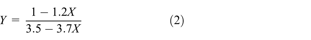
where X = ε/εpr, Y = σ/fpr, ε and σ are strain and stress of AAC, respectively; εpr is the peak strain of AAC and equals to 0.003 in this article; and fpr is the characteristic compressive strength and equals to 4 MPa in this article.
Finite element model verification
To verify the proposed numerical model, the loading sequence applied to the numerical model was the same as these in experiments. The experimental and simulated hysteretic curves are shown in Figure 13, and the simulated curve was approximated closely to the experimental one, excepting the portion in unloading stages. The discrepancies of hysteretic curves between experimental and finite element analysis results were mainly due to the assumption of simplified material models. As shown in Figure 14(a), the simulated stress distribution in specimen KJ-1 was concentrated in beam ends and column bases, which was similar to the observation in tests (Figure 7). The simulated stress and crack distribution on the AAC panels in specimen KJ-2 are depicted in Figure 14(b) and (c), and they were concentered at the diagonal loaded corner of each AAC panel. It was the same as the experimental results shown in Figure 8. In general, the proposed numerical model could properly simulate the mechanical response of the specimens.
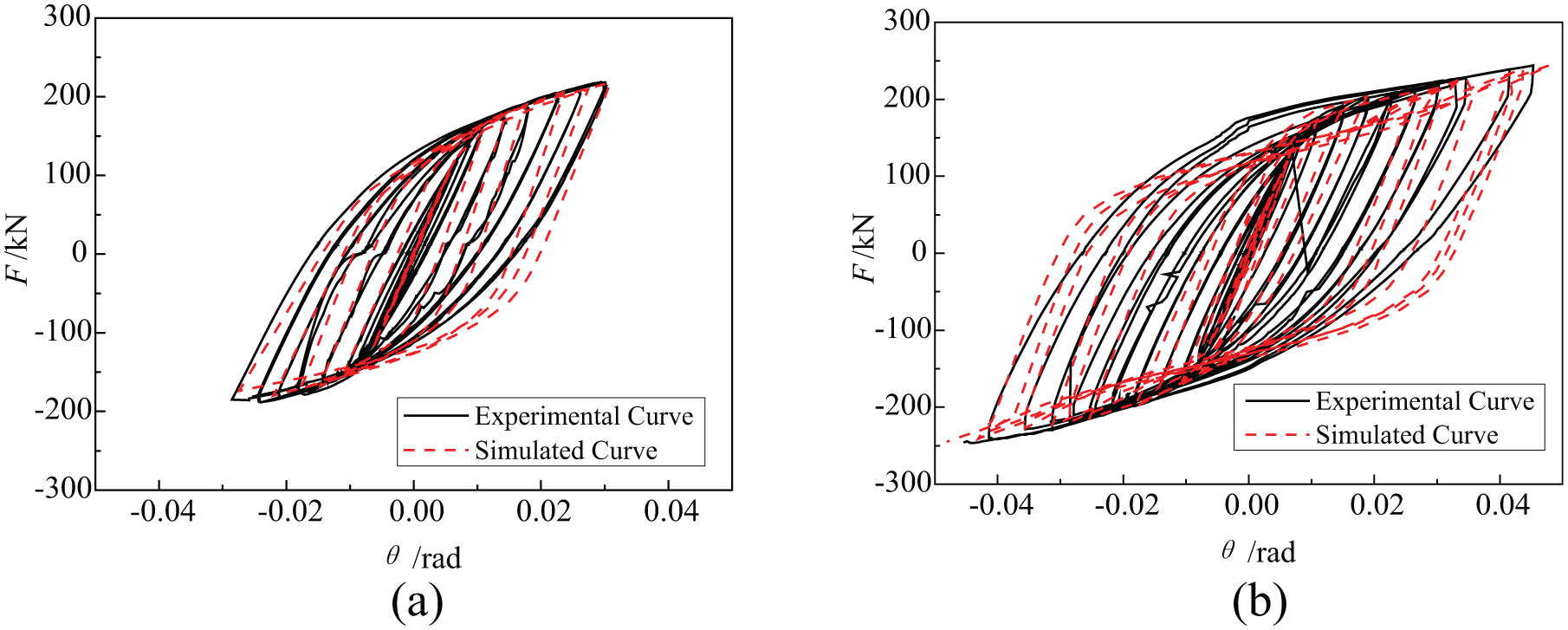
Comparison of experimental and simulated hysteretic curves: (a) specimen KJ-1 and (b) specimen KJ-2.
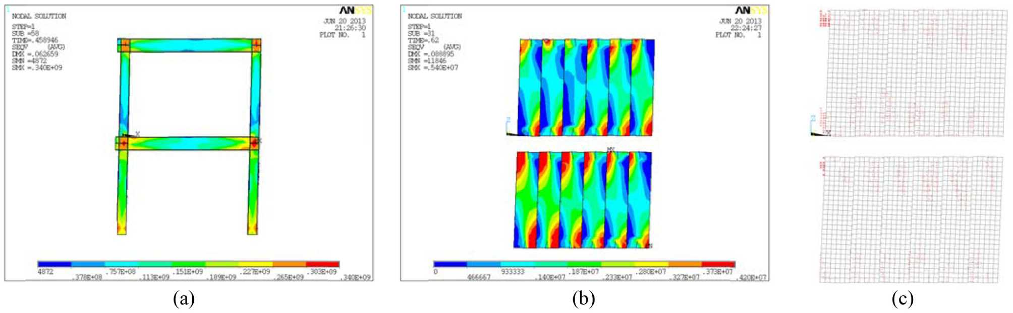
Simulated results of the specimens: (a) stress distribution on the steel frame of specimen KJ-1; (b) stress distribution on the AAC panels of specimen KJ-2; and (c) crack distribution on the AAC panels of specimen KJ-2.
Effect of BHA connections
The experimental research on BHA connections (Cao et al., under review) had demonstrated that the BHA connections could act as rigid connections under cyclic loads. The influence of BHA connections on the mechanical properties of steel frames should be similar to traditional rigid connections. Therefore, the BHA connections were replaced by rigid beam-to-column connections in the aforementioned numerical models to reduce the difficulty in numerical convergences. As no experimental work with the same AAC panel details as that used in this article could be found in literatures, the comparison between the simulated and experimental results in the last section, as shown in Figures 13 and 14, was used to testify the rationality of connection simplicity in numerical models.
Parametric analysis design
The details of two-storey and single-bay infilled frames used in parametric analyses are listed in Table 4. It was composed of Chinese H300×120×6×12 Grade Q235B beams and Chinese H250×200×8×12 Grade Q235B columns. In order to check for the effect of AAC panel width and thickness, a series of monotonic loading analyses were conducted by varying the two design parameters, respectively, as tabulated in Table 5. The loading pattern used in parametric analyses was the same as that in the experiments.
Detail of infilled frames in parametric analyses.
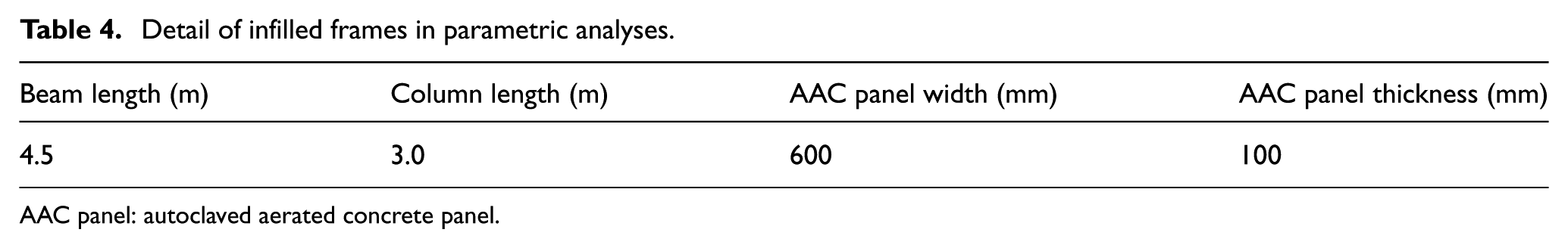
AAC panel: autoclaved aerated concrete panel.
Parametric analysis plan.
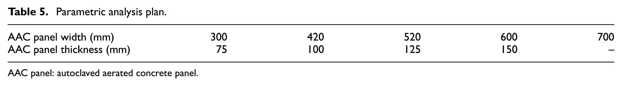
AAC panel: autoclaved aerated concrete panel.
Parametric analysis results and discussion
Figure 15 depicts the stress distribution on the AAC panels with 300 and 700 mm width when the load (F) at each storey reached 120 kN. For the same storey span, wider AAC panels leaded to a relatively smaller number of panels, which could improve the integrality of infill walls and the efficiency of load transfer between AAC panels. Therefore, only part of AAC panels in the model with narrow panels worked to resist lateral loads. In the contrary, more AAC panels took part in resisting lateral loads for the model with wider panels, as shown in Figure 15.
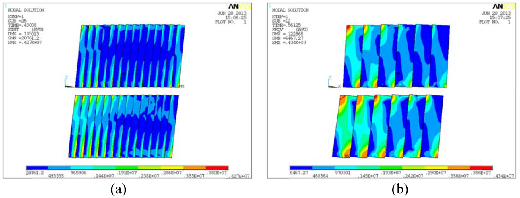
Stress distribution on AAC panel: (a) 300 mm and (b) 700 mm wide AAC panels (120 kN).
In addition, the stiffness and strength of AAC panels could be significantly increased with their thickness. As the parametric analysis results shown in Figures 16 and 17, both of the initial lateral stiffness and ultimate inter-storey shear force of infilled steel frames were linearly increased with AAC panel width and thickness, respectively.
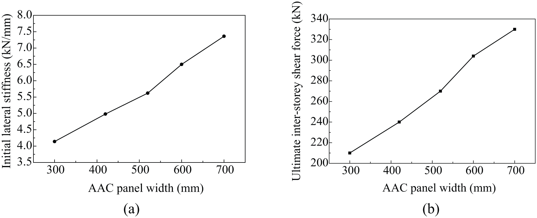
Parametrical analysis results with respect to AAC panel width: (a) initial lateral stiffness and (b) ultimate inter-storey shear force.
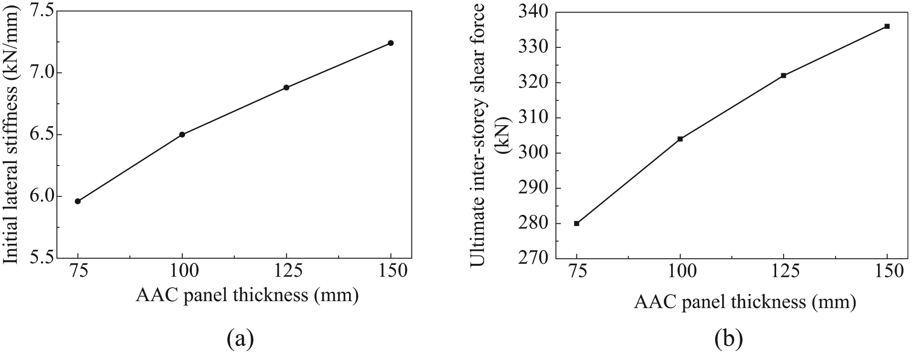
Parametrical analysis results with respect to AAC panel thickness: (a) initial lateral stiffness and (b) ultimate inter-storey shear force.
Conclusion
Two fabricated steel frames assembled by BHA connections were cyclic tested, and the effect of AAC panels and their dimensions on the mechanical properties of steel frames was analyzed via experimental and numerical results. Based on the above analyses, the conclusions are presented as follows:
The fabricated steel frames assembled by BHA connections could behave in a ductile manner under cyclic loading; meanwhile, they could provide sufficient stiffness and strength to resist lateral loads.
Compared with bare steel frames, AAC panels could increase the initial stiffness, peak load, ultimate storey drift, and energy dissipation capacity of structures, and postpone their failure.
After the severe cracking of AAC panels, the contribution of infill walls to structure stiffness was ignorable.
The mechanical behavior of infilled steel frames was influenced heavily by AAC panel width and thickness.
Footnotes
Declaration of Conflicting Interests
The author(s) declared no potential conflicts of interest with respect to the research, authorship, and/or publication of this article.
Funding
The author(s) disclosed receipt of the following financial support for the research, authorship, and/or publication of this article: This work described in article was supported by the National Natural Science Foundation of China (No. 51378147).